Go to File > Properties > Title to define the even-page header · Table of contents 3 Table of...
91
Training Prestressed concrete, construction stages, concrete checks
Transcript of Go to File > Properties > Title to define the even-page header · Table of contents 3 Table of...

Training Prestressed concrete,
construction stages, concrete checks

Table of contents
2
All information in this document is subject to modification without prior notice. No part or this manual may be reproduced, stored in a database or retrieval system or published, in any form or in any way, electronically, mechanically, by print, photo print, microfilm or any other means without prior written permission from the publisher. Scia is not responsible for any direct or indirect damage because of imperfections in the documentation and/or the software.
(1) © Copyright 2010 Scia Group nv. All rights reserved.

Table of contents
3
Table of contents
1 The post-tensioned bridge – tutorial from training ................................................................... 1
1.1 Project setup ................................................................................................................. 1 1.2 National annexes .......................................................................................................... 2
2 Model .............................................................................................................................................. 5
2.1 Structure ........................................................................................................................ 5
2.1.1 Cross-sections .......................................................................................................... 5
2.1.2 Beams ....................................................................................................................... 8
2.1.3 Supports .................................................................................................................. 10
2.1.4 Prestressing ............................................................................................................ 11 2.2 Load ............................................................................................................................. 20
2.2.1 Loadcases ............................................................................................................... 20
2.2.2 Loads ...................................................................................................................... 20 3 Construction stages ................................................................................................................... 23
3.1 Local beam history ..................................................................................................... 29 3.2 Automatic calculation of subintervals ...................................................................... 32
4 Mobile loads................................................................................................................................. 35
4.1 Preparation of mobile load in SEN ............................................................................ 36
4.1.1 The load group ........................................................................................................ 36
4.1.2 Mobile load track ..................................................................................................... 37
4.1.3 Unit load .................................................................................................................. 37
4.1.4 Load system database ............................................................................................ 37 4.2 Setup of generated loadcase ..................................................................................... 38 4.3 Definition of construction stages.............................................................................. 40 4.4 Evaluation of mobile loads - envelopes ................................................................... 42
5 Library of Named items .............................................................................................................. 44
5.1 Named fibres ............................................................................................................... 44 5.2 The named part of CSS .............................................................................................. 46 5.3 Named cuts .................................................................................................................. 47
5.3.1 For general CSS ..................................................................................................... 47
5.3.2 For database CSS .................................................................................................. 48 5.4 Named joints ............................................................................................................... 49
6 Analysis ........................................................................................................................................ 51
6.1 Linear analysis ............................................................................................................ 51 6.2 Construction stage analysis (TDA EN1992-1-1) ...................................................... 52 6.3 Construction stage analysis (TDA EN1992-2) .......................................................... 52
7 Check of prestressed concrete according to EN1992-1-1 ...................................................... 54
7.1 Concrete setup ............................................................................................................ 54
7.1.1 User defined section only........................................................................................ 55
7.1.2 Concrete area weakened by reinforcement bars .................................................... 56
7.1.3 Concrete area weakened by prestressed bars ....................................................... 56
7.1.4 Warning and errors ................................................................................................. 57 7.2 Member check, single check ..................................................................................... 57
7.2.1 Member check ........................................................................................................ 58
7.2.2 Single check ............................................................................................................ 59
7.2.3 Check in named items – fibres, cuts, joints, parts of CSS ...................................... 60
7.2.4 CSS characteristic, transformed ............................................................................. 61
7.2.5 Not calculated internal forces ................................................................................. 63 7.3 SLS – concrete checks ............................................................................................... 65
7.3.1 Prestress crack check ............................................................................................. 65
7.3.2 Allowable concrete stresses ................................................................................... 65

Table of contents
4
7.3.3 Check of prestressing reinforcement ...................................................................... 72 7.4 ULS – concrete checks .............................................................................................. 73
7.4.1 Prestress check response....................................................................................... 73
7.4.2 Prestress check diagram ........................................................................................ 76
7.4.3 Shear check ............................................................................................................ 80
7.4.4 Torsion check .......................................................................................................... 81
7.4.5 Allowable principal stresses .................................................................................... 82 8 Literature ...................................................................................................................................... 87

Ing. Lukáš Dlouhý Prestressed concrete, construction stages, concrete checks
1
1 The post-tensioned bridge – tutorial from training
This paper describes one typical postensioned prestressed concrete bridge built in construction stages. The traffic load is taken from EN1991-2 with respect of EN1990/A1. The code for check is according to EN1992-1-1.
1.1 Project setup
The new project is created using button New and Structure is selected.
The settings of the project are necessary to set in Project data. The structure type Frame XZ should be selected for the TDA analysis of the structure (only frame XZ should be analyzed using TDA). At least one material should be selected in the project - Concrete. When concrete material is selected then automatically Reinforcement material (nonprestressed) is offered to user. The Project level - Advanced is recommended. The Construction stages model should be selected for modelling of structure using construction stages. National code for analysis and check is necessary to select EC-EN. Each country has its own National annexes for Eurocodes.
The checkbox Prestressing should be turns on for modelling and calculation with prestressing in project. The Level of prestressing - Advanced is recommended. The checkbox Mobile loads should be turns on for mobile load analysis.

Ing. Lukáš Dlouhý Prestressed concrete, construction stages, concrete checks
2
1.2 National annexes
National code for analysis and check is necessary to select EC-EN. Each country has its own National annexes for Eurocodes. This annex is possible to define by National annex. In current version user has to fill in all national annexes himself. From the version 2010.1 all necessary national annexes will be prepared and stored in program. User will be able to select appropriate national annexes according to country.
When user opens setup manager he can define several national annexes which he needs. There is possible to assign appropriate flag for selected country.
Each national annex has its own values of national annexes. Now user defines national annexes himself in that place in the program. These values are possible to edit for each design code. EN1990,

Ing. Lukáš Dlouhý Prestressed concrete, construction stages, concrete checks
3
EN1991 and En1992 are important codes for us. National annexes for mentioned codes are shown in the following figures.
National annexes for EN1990 – basic of structural design
National annexes for EN1991 – wind + snow

Ing. Lukáš Dlouhý Prestressed concrete, construction stages, concrete checks
4
National annexes for EN1992 – concrete checks

Ing. Lukáš Dlouhý Prestressed concrete, construction stages, concrete checks
5
2 Model
2.1 Structure
2.1.1 Cross-sections
The structure is defined by standard modelling using in Scia Engineer (SEN). The cross-sections are defined in CSS library using button New. There are several predefined Precast and Bridge CSS.
The General CSS enables to user prepares completely different CSS himself. It is possible to define it using definition of polygons directly in SEN or import CSS from dwg or dxf format.

Ing. Lukáš Dlouhý Prestressed concrete, construction stages, concrete checks
6
The CSS in the drawing format has to be prepared by Lines and Polylines. Connect all polylines is necessary to do as first (Select curves>Connect curves). Then polylines are created.
The selection of polygons and polygons openings is necessary for proper import from drawing format. User selects Selection mode>Polygons and selects outer polyline. Then he switches to Polygons openings and selects the polylines representing the openings. Afterthat the CSS can be imported from drawing format to SEN as general CSS

Ing. Lukáš Dlouhý Prestressed concrete, construction stages, concrete checks
7
The cross-sections (CSS) should be also imported from previous similar SEN project.
The user can select which CSS will be import from user database file.
The dialog of CSS looks like following

Ing. Lukáš Dlouhý Prestressed concrete, construction stages, concrete checks
8
2.1.2 Beams
The beams are defined using item Structure>1D Member>Beam with following properties.
The following lengths of the beams will be defined in meters and appropriate CSS will be selected.
B1 1,0
B2 19,0
B3 1,0
B4 4,0
B5 21,0
B6 1,0
B7 4,0
B8 21,0
B9 1,0
B10 4,0
B11 15,0
B12 1,0

Ing. Lukáš Dlouhý Prestressed concrete, construction stages, concrete checks
9
The user can see table of the beams in Document>Structure>Members
The coordinates of the beam´s nodes are possible to modify by Table edit geometry.
The alignment of the CSS should be changed to the bottom using filter of the beam in ones step because of different CSS in the structure.

Ing. Lukáš Dlouhý Prestressed concrete, construction stages, concrete checks
10
2.1.3 Supports
The supports should be defined using Structure > Model data>Support>Point on beam. The Z support is defined on support in the middle of the beam B1, B3, B9 and B12. The X, Z support is defined in the middle of the beam B6.
The additional support in the first beam has to be defined twice, because it is different during the construction stages.
The 3D perspective model of the structure looks like following.

Ing. Lukáš Dlouhý Prestressed concrete, construction stages, concrete checks
11
2.1.4 Prestressing
The loadcase type Prestress has to be defined for definition of the postensioned tendons. The loadcase is defined using Load cases, Combinations > Load cases.
The postensioned tendons are possible to defined now in Structure>Tendons>Internal postensioned tendons. There are many input values and the most important is explained. The following items will be defined in this example.

Ing. Lukáš Dlouhý Prestressed concrete, construction stages, concrete checks
12
Name – from 1e_01 up to 4e_16 – 30 tendons
Layer – the four different layers were defined according to construction stages which will be defined later - Stage1, 2, 3 and 4. The name of tendon beginning on number 1 belongs to layer Stage 1 and other...
Geometry input – type Source geometry is used; there are three possibilities of definition of tendon geometry
o Source geometry – user defines geometry in library of SG
o Direct input – user defines geometry of tendon in 3D window directly; the imported geometry from CAD program should be used by this option
o Reference line with source geometry – the source geometry is winded on user defined reference line
Allocation – the beams (slabs) where tendons are allocated on should be selected
LCS–X – the beam where start the local system of tendons; it could be a first beam from allocation or directly selected beam

Ing. Lukáš Dlouhý Prestressed concrete, construction stages, concrete checks
13
Projection of intermediate points – this option is relevant only in case of Hanging nodes
o Proportionally – user defines the length where the tendon effects are projected on
Way of location – begin
First node – the beginning of projected tendon effects to the beam is from the first node of the allocated beam
Location – distance from the beginning of the beam
Way of location – end
Last node – the beginning of projected tendon effects to the beam is to the last node of the allocated beam
Location – distance from the end of the beam
o Perpendicularly – tendon is projected directly in perpendiculars to the beams
The hanging nodes are not available for TDA calculation
LCS – type of local axis of tendon
o Standard – local axis of tendon is the same as local axis of the allocated element
o Z by vector – user sets the vector by points X and Z and the direction of z is according to these values
o Z by point – user sets the point which shows direction of local coordinate system

Ing. Lukáš Dlouhý Prestressed concrete, construction stages, concrete checks
14
o Z from UCS – XXX
Source geometry – 30 types of SG will be defined by user
The source geometry should be also imported from user database file.

Ing. Lukáš Dlouhý Prestressed concrete, construction stages, concrete checks
15
Origin of SG – type of origin of SG
o Offset in LCS – the origin can be set related to local coordinates of the beam
o Coordinate in GCS – the origin is set related to global coordinates of the file
Material – material Y1770S7-15,7 is used;

Ing. Lukáš Dlouhý Prestressed concrete, construction stages, concrete checks
16
Number of elements in tendon– 15 tendon has 15 strands
Number of tendons in group – 1 only 1 tendon exists with the same properties and geometry
Diameter of the duct – 80mm
Stressing
o Type of stressing – type 3
o Prestressing from – End
o Stress during correcting – 1410MPa
o Initial stress – 1410MPa Another value are taken from default settings Libraries>Setup > Prestressing-Postensioned

Ing. Lukáš Dlouhý Prestressed concrete, construction stages, concrete checks
17
The parameters brief table of tendon is possible to view in document Structure>Tendons>Internal tendons.
The tendon shorterm losses should be dispalyed for each selected tendons

Ing. Lukáš Dlouhý Prestressed concrete, construction stages, concrete checks
18
The tendons are drawing in 3D window depending on View parameters settings.
There are three possibilities of displaying of tendons in 3D window – thin line, diameter, 3D. Anchors and directions of stressing are also possible to display. 3D drawing with rendered model can give very nice pictures.

Ing. Lukáš Dlouhý Prestressed concrete, construction stages, concrete checks
19

Ing. Lukáš Dlouhý Prestressed concrete, construction stages, concrete checks
20
2.2 Load
2.2.1 Loadcases
The loadcases have to be defined before construction stages are defined. The following list of load cases will be defined. There are several possibilities of load definition.
Permanent
o Type
Standard – necessary for definition of stages in construction stages library, could be empty loadcase used only for definition of stages
Selfweight – loadcase from load of selweight
Prestress – necessary for definition of prestressing
o Loadgroup
Link to library of Load group – see (4.1)
Variable
o Specification
Standard
Temperature – only thermal load should be defined in this LC
o Loadgroup
Link to library of Load group – see (4.1)
2.2.2 Loads
Load is defined according to type of load using Loads. For example - permanent load (road, safety fence and other bridge accessories) is defined in loadcase LC17-Another permanent – type permanent

Ing. Lukáš Dlouhý Prestressed concrete, construction stages, concrete checks
21
The definition of the load value is available in Loads>Line force on beam and user defined value -61,3kN/m.
2.2.2.1 Temperature load
The variable loadcase with specification temperature has to be defined. The temperature load is defined in Load>Thermal on beam.
The linear thermal load will be defined.
LC – Temperature–
o Top delta - 8°C
o Bottom delta 0°C
LC – Temperature+
o Top delta +10,5°C
o Bottom delta 0°C

Ing. Lukáš Dlouhý Prestressed concrete, construction stages, concrete checks
22
The temperature load is drawn in 3D window following (using triangles).

Ing. Lukáš Dlouhý Prestressed concrete, construction stages, concrete checks
23
3 Construction stages
The construction stages are necessary to define for time dependant analysis (TDA). The User has to define Type - Time analysis in Setup of construction stages.
Then it is necessary to define each construction stage using three dot buttons. There are several important values
Name – ST1 – ST19
Description – description of appropriate stage
Global time – global time of time axis in days
Number of subintervals – number of subintervals in appropriate stage, the creep and shrinkage increment are calculated in this subintervals
Ambient humidity – in percentage, needed for calculation of shrinkage
Last construction stage – checkbox which signed last construction stages, the stages after that are service stages, variable load applied before Last construction stage cannot be used in another stage.
Permanent load case – load case type permanent – each stage has to have only one loadcase type permanent (longterm variable), this loadcase could be also empty only (for measurement-without load), but it is necessary for creation of stages
Prestress type loadcase – optional loadcase, by this loadcase are determined prestressing tendons in appropriate stage
Type of generated combination – user has several opportunity which type of combination will be automatically generated according to selected code in project data
Variable action button – the variable loadcase is possible to add into selected stage by this button (see chapter 4.3)

Ing. Lukáš Dlouhý Prestressed concrete, construction stages, concrete checks
24
The all stages will be defined by this way. The total content of the stages is following.

Ing. Lukáš Dlouhý Prestressed concrete, construction stages, concrete checks
25
The very user friendly list of construction stages is possible to add into document.
The construction stages are defined now is necessary to assign which members and supports belong to which construction stages. The members are defined by button Members>Add members and selected appropriate member in selected stage.

Ing. Lukáš Dlouhý Prestressed concrete, construction stages, concrete checks
26
The supports are defined in similar way Supports> Add supports.
The support on beam B1 is defined in the ST1 (X,Z support) and removed in ST3. The support (Z only) is added in ST3.
The whole structure will be defined by this way described in upper figures. The graphical presentation in 3D window is following during of construction.

Ing. Lukáš Dlouhý Prestressed concrete, construction stages, concrete checks
27

Ing. Lukáš Dlouhý Prestressed concrete, construction stages, concrete checks
28

Ing. Lukáš Dlouhý Prestressed concrete, construction stages, concrete checks
29
3.1 Local beam history
One from the most important setting for time dependant analysis is Local Beam settings (LBH). This LBH will be assigned to each member.

Ing. Lukáš Dlouhý Prestressed concrete, construction stages, concrete checks
30
Time of casting - it is time of casting of concrete in days in local time axis related to the global time axis. It is possible to input negative value. The linear support hasn’t to be used in this case. The ageing of the concrete starts in this time. It is significant for age of concrete for creep calculation. An example - construction stage 1 - global time 5 days; time of casting -3 days. It means that global time of casting is 2 days. The user doesn’t have to input linear support - formwork
Time of end of curing - it is time of end of curing of concrete. If phased CSS is used, then it is time of end of cuing of the first phase of CSS. It is significant time for calculation of shrinkage.
Time of end of curing of composite phases - it is significant only for phased CSS, this time is end of curing of the second, third...phase of CSS if exists. It is significant time for calculation of shrinkage of second, third phase of CSS again.
Time of releasing of displacement in X(Z) direction – time when formwork in X(Z) direction is replaced.
The displaying of LBH in 3D window is as linear support (formwork).
More LBH is possible to edit in one step
The LBHs are possible to view in document.

Ing. Lukáš Dlouhý Prestressed concrete, construction stages, concrete checks
31
The colour drawing in 3D windows depends on settings in Setup> Colour/lines > Palette settings.
The drawing according to stages is possible to set by right click in 3D window Set view parameters for all and set which components of stages will be drawn.

Ing. Lukáš Dlouhý Prestressed concrete, construction stages, concrete checks
32
3.2 Automatic calculation of subintervals
The user has to define in each stage number of subintervals. There is also possibility to defined total number of subintervals in whole construction in Setup of stages> Total number of subintervals. The time axis will be divided according to the same logarithm increment into whole construction.

Ing. Lukáš Dlouhý Prestressed concrete, construction stages, concrete checks
33
Total number of subinterval can be bigger then user defined because of following:
At least one subinterval has to be in each stage
Keeping stress (duration of shorterm relaxation) is also considered as time point
This option is possible also in Time axis> subintervals. The user set total number of subintervals and could admit or refuse this offered solution of subintervals.

Ing. Lukáš Dlouhý Prestressed concrete, construction stages, concrete checks
34

Ing. Lukáš Dlouhý Prestressed concrete, construction stages, concrete checks
35
4 Mobile loads
The load system gr1a (according to table 4.4 EN1991-2) is the most efficient load system for design and check of bridges. This system consists from
Load model – LM1
o Tandem system – TS
o Uniformly distribute load – UDL
Pedestrian or cyclist load
The combinations coefficients (0, 1 a2) are different for the separate loads in this load system according to table A2.1 from the EN 1990/A1. The procedure of modelling and check using characteristic, frequent and quasi-permanent combination including load system gr1a is different from the using of standard procedure with loadcases which belongs to appropriate loadgroup with defined combination coefficient in menu Project.
The rules for SLS combination according to tab. A2.6 from EN1990/A1
Permanent Prestress The dominant
variable (traffic)
The subordinate variable
(temperature)
Characteristic Gi P 1,0*Qk1 0* Qki
Frequent Gi P 1*Qk1 2* Qki
Quasi-permanent Gi P 2* Qki 2* Qki
Ing. Lukáš Dlouhý Prestressed concrete, construction stages, concrete checks
36
4.1 Preparation of mobile load in SEN
4.1.1 The load group
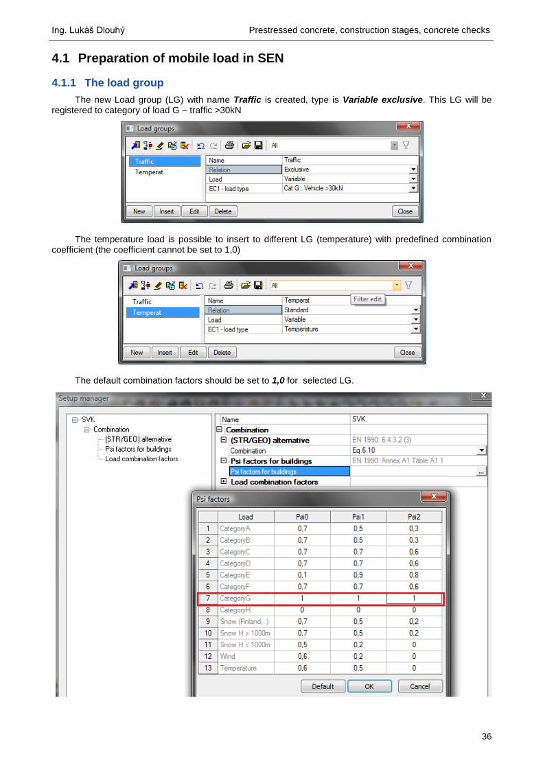
The new Load group (LG) with name Traffic is created, type is Variable exclusive. This LG will be registered to category of load G – traffic >30kN
The temperature load is possible to insert to different LG (temperature) with predefined combination coefficient (the coefficient cannot be set to 1,0)
The default combination factors should be set to 1,0 for selected LG.

Ing. Lukáš Dlouhý Prestressed concrete, construction stages, concrete checks
37
4.1.2 Mobile load track
New mobile load track (TR1) has to be defined by user Mobile loads > New mobile load track. The first and last node will be selected and track will be automatically defined on whole structure
4.1.3 Unit load
New Unit load (UL) will be defined by user Mobile loads > Unit loads.
4.1.4 Load system database
The new Load system databases will be defined for each type of combination including combination coefficients for characteristic and frequent combination. Mobile loads > Load system database
Traf_char – Load system for characteristic combination 1,0*TS+1,0*UDL Traf_fre – Load system for frequent combination 0,75*TS+0,4*UDL

Ing. Lukáš Dlouhý Prestressed concrete, construction stages, concrete checks
38
4.2 Setup of generated loadcase
Two groups of generated loadcase should be set in Setup of generated loadcase. The same LG - Traffic should be assign to each group of generated LC. The components Vz and My will be evaluated.
T_char – Unit loads (UL) + load system database (Traf_char)
T_fre – Unit loads (UL) + load system database (Traf_fre)

Ing. Lukáš Dlouhý Prestressed concrete, construction stages, concrete checks
39
The envelopes of LC will be automatically generated after linear calculation finish. These generated LC will be added into appropriate stages.

Ing. Lukáš Dlouhý Prestressed concrete, construction stages, concrete checks
40
4.3 Definition of construction stages
The separated construction stages were created in construction stages library (see). The appropriate envelopes of variable LC will be add to each construction stage according to type of generated combination
o Char_1 – characteristic combination time 365 days MSP-characteristic UL-Traf_char-Min My UL-Traf_char-Max My UL-Traf_char-Min Vz UL-Traf_char-Max Vz Temperature+ Temperature-
o Fre_1– frequent combination time 365,1days MSP-frequent UL-Traf_fre-Min My UL-Traf_fre-Max My UL-Traf_fre-Min Vz UL-Traf_fre-Max Vz Temperature+ Temperature-

Ing. Lukáš Dlouhý Prestressed concrete, construction stages, concrete checks
41
o QP_1– quasi-permanent combination time 365,2days MSP-quasi-permanent Temperature+ Temperature-
o ULS_1 – ULS(STR) combination time 365,3 days ULS(STR)-combination UL-Traf_char-Min My UL-Traf_char-Max My UL-Traf_char-Min Vz UL-Traf_char-Max Vz

Ing. Lukáš Dlouhý Prestressed concrete, construction stages, concrete checks
42
4.4 Evaluation of mobile loads - envelopes
The evaluation of maximum and minimum envelopes in one presentation in results is possible using Loadcases, Combination>Results classes.
Char_extrem_My – extreme of envelopes of mobile loads for characteristic combination o UL_Traf_char_maxMy o UL_Traf_char_minMy
Fre_extrem_My – extreme of envelopes of mobile loads for frequent combination o UL_Traf_fre_maxMy o UL_Traf_fre_minMy

Ing. Lukáš Dlouhý Prestressed concrete, construction stages, concrete checks
43
The internal force are possible to see in Results> Internal forces. The user can select in Type of loads – Class and form the list of classes selects Char_extrem_My. The extreme moment is drawn from minimum and maximum envelopes of mobile load for characteristic combination.
And for frequent combination.

Ing. Lukáš Dlouhý Prestressed concrete, construction stages, concrete checks
44
5 Library of Named items
The library of Named items is possible to view in Library>Named item.
The user has possibility to defined following named items in this library
Fibre – for evaluation of results of allowable concrete stresses in predefined named fibres only
Part of cross-section - for evaluation of results of allowable principal stresses in predefined named part of cross-section if phased CSS exists
Cut - for evaluation of results of allowable principal stresses in predefined named cuts of cross-section
Joint – for evaluation of results of shear stress in construction joint in predefined named joint if phased CSS exists
5.1 Named fibres
When user defined named items in library, then is necessary to linked named items to appropriate fibres, cuts, part of CSS and joints in selected CSS. The fibres and part of CSS are possible to define in selected CSS by button Edit named items.

Ing. Lukáš Dlouhý Prestressed concrete, construction stages, concrete checks
45
To the upper fibres with number 4, 5, 6 will be assigned named fibre Upper from named fibre library.
To the lower fibres with number 9 10, 18, 19 will be assigned named fibre Lower from named fibre library.

Ing. Lukáš Dlouhý Prestressed concrete, construction stages, concrete checks
46
5.2 The named part of CSS
The named part of CSS could be defined in case of phased CSS in upper left part of dialog.

Ing. Lukáš Dlouhý Prestressed concrete, construction stages, concrete checks
47
5.3 Named cuts
5.3.1 For general CSS
The named cuts are possible to add to the cut in Editor of general CSS.
The definition of new cut is possible by button Add cut in editor of general CSS.
There are two possibilities how to defined a cut
Point – cut is defined in selected point
Fibre + offset – cut is defined in offset from selected fibre There is also possibility to set only cut in direction Y or Z.

Ing. Lukáš Dlouhý Prestressed concrete, construction stages, concrete checks
48
The vertical cut in the left beam of CSS was defined.
5.3.2 For database CSS
The definition of new cut is possible by button Edit cuts for database CSS.
The property of Edit cuts dialog for database CSS is following.

Ing. Lukáš Dlouhý Prestressed concrete, construction stages, concrete checks
49
5.4 Named joints
The named joint could be defined in case of phased CSS using button Edit named joint in General CSS dialog.
The CSS is solid, that’s why no joints are displayed in Joint dialog.

Ing. Lukáš Dlouhý Prestressed concrete, construction stages, concrete checks
50
The following properties will be displayed in case of phased CSS.

Ing. Lukáš Dlouhý Prestressed concrete, construction stages, concrete checks
51
6 Analysis
6.1 Linear analysis
The linear analysis has to be done for generation of envelopes from mobile loads (see 4.2).
Mesh and Solver setup values used in analysis is possible to modify in Setup> Mesh, Solver.
After successful calculation appear following message.

Ing. Lukáš Dlouhý Prestressed concrete, construction stages, concrete checks
52
6.2 Construction stage analysis (TDA EN1992-1-1)
The construction stage analysis is performed for calculation of effects of stages with influence of effects creep and shrinkage (TDA). Effects of creep and shrinkage are performed according to EN1992-1-1 annex B.
6.3 Construction stage analysis (TDA EN1992-2)
There is also possibility to run calculation of TDA (creep and shrinkage calculation) according to code
EN 1992-2 annex B, but some necessary steps have to be done.
The main idea is to include another type (EN 1992-2) of material into one code EN 1992. There are
two groups of materials (EN1992-1-1 and EN1992-2). Due to implementation of calculation creep and
shrinkage of concrete according to EN 1992-2 is suitable to present new type of concrete material. These
materials are signed similar as standard EN material with suffix EN1992-2. New materials are following:

Ing. Lukáš Dlouhý Prestressed concrete, construction stages, concrete checks
53
Materials with fck < 50 MPa is not available.
Cement class – only type R (read only)
Silica fume – checkbox YES/NO – influence on calculation of creep and shrinkage acc. to EN 1992-2
annex B
Relative humidity - The code EN 1992-2 is not allowed calculation creep and shrinkage for relative
ambient humidity bigger then 80%. When user uses concrete material according to EN1992-2 and sets RH>80% then during start TDA calculation appears warning about relative humidity.
Long term delayed strain estimation
Long term delayed strain estimation is used acc. to chapter B.105, implementation of formula B.128. The coefficient calculated with that formula is applied on formulas for concrete aged 1 year or more:
o (t;t0) (B.1) and cd,0 (B.11) for concrete EN1992-1-1
o cd(t) (B.116) and b(t;t0) (B.118) for concrete EN1992-2
User can set this option in material database in property of concrete for both EN concrete (see following)

Ing. Lukáš Dlouhý Prestressed concrete, construction stages, concrete checks
54
7 Check of prestressed concrete according to EN1992-1-1
The check of prestressed concrete is performed only according to EN1992-1-1. There are not any implementation of special check according to EN1992-2 which is code for design of bridges. There is only possible to used special TDA calculation according that code (see 6.3).
7.1 Concrete setup
The final concrete setup is synthesis of national dependent values and standard setup independent values.
Code dependent values are possible to see in Project Data>Code>National annexes.
Code independent values are possible to see in Libraries>Concrete setup.
Complete setup is visible in appropriate concrete check filtered according to check. For instance see concrete setup for Allowable stresses of concrete.

Ing. Lukáš Dlouhý Prestressed concrete, construction stages, concrete checks
55
Some important settings from concrete setup will be explained in the following chapters
7.1.1 User defined section only
This functionality is suitable for fast performing of concrete checks only in user defined section, where is supposed the most loaded structure and extreme results. Check is performed only in those user defined d section and duration of check is shorter. It is available for all concrete checks and design.

Ing. Lukáš Dlouhý Prestressed concrete, construction stages, concrete checks
56
7.1.2 Concrete area weakened by reinforcement bars
When this checkbox is switch ON, then area of concrete CSS is reduced by bars. It has effects on all concrete 1D checks.
7.1.3 Concrete area weakened by prestressed bars
When this checkbox is switch ON, then area of concrete CSS is reduced by bars. It has effects on all concrete 1D checks.

Ing. Lukáš Dlouhý Prestressed concrete, construction stages, concrete checks
57
7.1.4 Warning and errors
When some check is performed then warning or error can be printed in the table.
All warnings and errors are stored in the concrete setup.
7.2 Member check, single check
The modelled structure can be checked by two ways:
globally using Memebr check
detailed using Single check

Ing. Lukáš Dlouhý Prestressed concrete, construction stages, concrete checks
58
7.2.1 Member check
Member check is performed from the standard concrete check service. The results are displayed along the selected members. The output table has different output according to extreme:
Global – one extreme result of all checked members
Member – one extreme results of each checked member
Section – extreme results in each section along all checked members

Ing. Lukáš Dlouhý Prestressed concrete, construction stages, concrete checks
59
Cross-section – one extreme results of all checked cross-section
7.2.2 Single check
Almost all concrete checks has single check. It is detailed analysis of one cross-section. Action button to go there is following in the bottom of service.
Dialogue of single check provided to user selects:
Extreme of normal forces (N+; N-; Vz+; Vz-...)
Section along the selected member
Appropriate tabsheet with detailed results. Tabsheets are dependent on type of concrete service, but mainly there are following:
o Cross-section
o Loads
o Strain
o Stress
o Stress/strain diagram

Ing. Lukáš Dlouhý Prestressed concrete, construction stages, concrete checks
60
7.2.3 Check in named items – fibres, cuts, joints, parts of CSS
Definition of named items was described in chapter 5. Here the using in concrete checks will be explained. The idea of using named part is to get user friendly results and to increase speed of check. SEN supports following named items in the following services.
Named fibres
o Check response
o Allowable stresses of concrete
Named cuts
o Allowable principal stresses
Named joints
o Check response – check of shear in construction joint
o Design As
Named parts of CSS
o Check response
o Allowable stresses of concrete
o Allowable principal stresses For instance you can see results of allowable concrete stress for upper fibres
for member check

Ing. Lukáš Dlouhý Prestressed concrete, construction stages, concrete checks
61
for single check – only named fibres are available in single check
7.2.4 CSS characteristic, transformed
The service of CSS characteristic is service which can provide to user all necessary information about the CSS. This service is situated in Concrete > 1D member.

Ing. Lukáš Dlouhý Prestressed concrete, construction stages, concrete checks
62
This service performs calculation of geometrical properties of cross-section with including the following:
the prestressed reinforcement
the non-prestressed reinforcement
ducts of tendons
time
Type of characteristic with two items
o normal (only one check box from concrete, reinforcement and tendons can be switched on)
o transformed
Calculated components - three check boxes
o concrete (for transformed characteristic, this check box will be always switched on)
o reinforcement
o tendons
Subtracting from concrete will be active if the check box Concrete is switched on
o reinforcement
o tendon
o ducts
Characteristic related to with the following items
o to centre of gravity of cross-section
o to centre of gravity of cross-section phase ( new combo Phase of cross-section with the
following items:
all phases,
by selected combination,

Ing. Lukáš Dlouhý Prestressed concrete, construction stages, concrete checks
63
defined by user
o to selected named fibres (new combo with named fibres will be active)
o to the point (new properties for definition y and z coordinates will be active)
Values
o the values for normal characteristic
A, Iy, Iz,ty,tz,Sy,Sz,bw, Wy+, Wy-, Wz+, Wz-, iy, iz
o the values for transformed characteristic
Ai, Iyi, Izi,tyi,tzi,Syi,Szi; Wyi+, Wyi-, Wzi+, Wzi-, iyi, izi The results can be following:
7.2.5 Not calculated internal forces
The frame XZ which is used for the time dependent analysis doesn’t respect effects of torsion in this project. The envelopes of mobile loads for extreme Mx (torsion moment) should be analyzed on different project type frame XYZ. The value of Mx should be defined in project Frame XZ as Not calculated internal force.
The user should defined not calculated internal forces in menu Loads>Not calculated internal forces for selected loadcase.
The dialog for definition of Not calculated internal forces is following. There are several types. We use type Mx.

Ing. Lukáš Dlouhý Prestressed concrete, construction stages, concrete checks
64
Distribution should be following; type Polynomic is used for definition only in one section near the second support.
The value of Mx is defined in this dialog.
The displaying of not calculated internal forces in 3D window is following

Ing. Lukáš Dlouhý Prestressed concrete, construction stages, concrete checks
65
7.3 SLS – concrete checks
7.3.1 Prestress crack check
The cracks of the prestressed members are calculated according to chapter 7.3 from EN1992-1-1 and check is performed in service Concrete>Member check>check of prestressed concrete>Crack control. The prestressed structure is with bonded tendons and will be checked for frequent combination according to table 7.1N from EN1992-1-1. The exposure class is set in chapter 7.3.2.2 as XD3. The decompression has to be checked in this case.
7.3.2 Allowable concrete stresses
7.3.2.1 Domain knowledge of allowable concrete checks
The explanation of displayed values is following
The stress before and after anchoring
o In compression
cc,max – allowable stress in compression before and after anchoring, defined in chapter 5.42 in EN1992-1-1
)(6max, tfk ckcc (5.42)
k6 = 0,6 (for pretensioned concrete is possible to increase allowable stress on value 0,7 when it is verified that cracks don’t appear)
c,aa – calculated stress in concrete,
o In tension
cc,max – allowable concrete stress in tension before and after anchoring; defined in Concrete setup and default is 0MPa
c,aa – calculated stress in concrete,
Stress from SLS combination o Characteristic combination – longitudinal cracks
In compression
cc,ch – allowable concrete stress in compression from SLS characteristic combination, only for exposure class XD, XF a XS.
o )(1, tfk ckchcc (7.2.(2))
o k1 = 0,6
cq,min – minimal stress in concrete after application selweight all permanent and variable loads
In tension
fct,eff - allowable concrete stress in tension from SLS characteristic combination,
The value fct,eff is possible to set in Concrete setup>Allowable stresses: o fctm – the mean axial tensile strength o fctm,fl – the mean flexural tensile strength
fctm,fl = max{(1,6-h/1000)*fctm; fctm)}

Ing. Lukáš Dlouhý Prestressed concrete, construction stages, concrete checks
66
h total depth of CSS
cq,max – maximal stress in concrete after application selweight all permanent and variable loads
o Quasi-permanent combination – great creep In compression
cc,qp – allowable concrete stress in compression from SLS quasi-permanent combination, linear creep may be assumed
o )(2, tfk ckqpcc (7.2.(3))
o k2 = 0,45
clt,min – minimal stress from longterm load In tension
fct,eff,qp – allowable concrete stress in tension from SLS quasi-permanent combination, The value fct,eff,qp is possible to set in Concrete setup>Allowable stresses; default 0MPa
clt,max – maximal stress from longterm load
Other not checked, only drawn
p,inc – increment of stress from selected LC Some important values needed for calculation is recommended to set before check is performed.
7.3.2.2 Exposure class
The exposure class of concrete is possible to set in Concrete setup>Design defaults. The check of allowable concrete stresses and crack width depends on this exposure class. The class XD3 is set in this example.
The exposure class for each member is also possible to set by Member data.

Ing. Lukáš Dlouhý Prestressed concrete, construction stages, concrete checks
67
7.3.2.3 The factor for prestressing used in allowable concrete stresses
The upper and lower factors of prestressing force for check of allowable concrete stresses are possible to set in Concrete setup>SLS>Prestressing.
7.3.2.4 The factors for check of allowable concrete stresses
The factors for the calculation of limit values of concrete stresses from the code EN1992-1-1 is possible to set in Concrete setup>Allowable stresses.

Ing. Lukáš Dlouhý Prestressed concrete, construction stages, concrete checks
68
7.3.2.5 The check of Allowable concrete stresses
The user has possibility to perform this check in Concrete>Member check>Check of prestressed concrete>Allowable concrete stresses. The results of the check will be calculated and drawn for selected combination and value. For instance Check value of the SLS characteristic combination in 100 years is following.
The output table with extreme Member is following.

Ing. Lukáš Dlouhý Prestressed concrete, construction stages, concrete checks
69
For the selected values cc,ch and cq,min are results following
and output table is following

Ing. Lukáš Dlouhý Prestressed concrete, construction stages, concrete checks
70
The concrete stress should be calculated for selected fibre only
Then results for upper fibres are following

Ing. Lukáš Dlouhý Prestressed concrete, construction stages, concrete checks
71
The detailed analysis only in one section is possible using button Single check

Ing. Lukáš Dlouhý Prestressed concrete, construction stages, concrete checks
72
7.3.3 Check of prestressing reinforcement
7.3.3.1 Domain knowledge
The explanation of displayed values is following
The stress before anchoring
o p,max – allowable stress in prestressing before anchoring
};min{ 1.021max, kppkp fkfk (5.41)
k1 = 0,8; k2 = 0,9
k3 = 0,95 (p,max = k3*fp01,k) if special measurement of prestress force is applied
o p,pa – calculated stress before anchoring,
The stress after anchoring
o p,m0 – allowable stress in prestressing after anchoring,
};min{ 1.0870 kppkpm fkfk (5.43)
k1 = 0,75; k2 = 0,85
o p,aa – calculated stress after anchoring
The crack limitation from SLS characteristic combination during service – cracks and deformation
o pm – allowable stress in prestressing from SLS characteristic combination
pkpm fk5(7.2(5))
k5 = 0,75
o p,LTL – calculated stress after longterm losses
o pq,min – minimal stress in concrete after application selweight all permanent and variable loads in prestressing
o pq,max – maximal stress in concrete after application selweight all permanent and variable loads in prestressing
Others not checked stresses, only drawn
o pq,max – pq,min – the range of stresses in prestressing from maximal and minimal load in selected combination (envelopes of mobile loads)
o p,un – unbalanced stresses, difference of stresses calculated from the strain determined from structural analysis once as elastic stress (Hook´s law) and the second stresses as nonlinear stress-strain relationship
o p,inc – increment of stress from selected LC
The factors for the calculation of limit values of concrete stresses from the code EN1992-1-1 is
possible to set in Concrete setup>Allowable stresses.

Ing. Lukáš Dlouhý Prestressed concrete, construction stages, concrete checks
73
The user has possibility to perform this check in Concrete>Member check>Check of prestressed concrete>Check of prestressing reinforcement. The results of the check will be calculated and drawn for selected combination and value. For instance Check value of the SLS characteristic combination in 100 years is following.
The output table with extreme Member is following.
7.4 ULS – concrete checks
7.4.1 Prestress check response
The CSS response on acting combination is calculated in this check. The check is in Concrete>Member check>Check of prestressed concrete>Check response. The results of the check will be calculated and drawn for selected combination and value. There are following values for selection

Ing. Lukáš Dlouhý Prestressed concrete, construction stages, concrete checks
74
eps_cc – the strain in concrete under compression
eps_sc – the strain in nonprestressed reinforcement under compression
eps_st– the strain in nonprestressed reinforcement under tension
eps_tt – the strain in prestressed reinforcement under tension
Vzu – the shear resistance
Tu – the torsional resistance
Vrdi – the resistance of shear in construction joint
The results are calculated and drawn for F17-EN-ULS(STR) - check value.
The output table with extreme Member is following.

Ing. Lukáš Dlouhý Prestressed concrete, construction stages, concrete checks
75
The strain in concrete under compression for F17-EN-ULS(STR) – eps_cc.
The strain in tendons under tension for F17-EN-ULS(STR) – eps_tt.

Ing. Lukáš Dlouhý Prestressed concrete, construction stages, concrete checks
76
7.4.2 Prestress check diagram
The resistance of CSS acting by combination of moment and normal force is calculated using interaction diagram in this check. The check is in Concrete>Member check>Check of prestressed concrete>Check capacity. The default setup options are following:
The recommended type of interaction diagram is following:
When compression is dominant then NuMu is suitable because when structure is deformed by compression then moment is also increased
When tension is dominant then Nu is suitable
When pure bending is dominant then Mu is suitable The results of the check will be calculated and drawn for selected combination and value. There are
following values for selection

Ing. Lukáš Dlouhý Prestressed concrete, construction stages, concrete checks
77
Nu – capacity in axis x (axial capacity)
Myu – moment capacity in direction y
Mzu – moment capacity in direction z
Vzu – shear capacity
Tu – torsional capacity
The moment capacity in direction y for F17-EN-ULS(STR) – Myu
The axial capacity for F17-EN-ULS(STR) – Nu

Ing. Lukáš Dlouhý Prestressed concrete, construction stages, concrete checks
78
The output table for F17-EN-ULS(STR)
The results ain single checks are following:
Vertical section of interaction diagram

Ing. Lukáš Dlouhý Prestressed concrete, construction stages, concrete checks
79
Horizontal section of interaction diagram
3D interaction adiagram

Ing. Lukáš Dlouhý Prestressed concrete, construction stages, concrete checks
80
7.4.3 Shear check
The shear check is performed in Check response and check capacity as value Vzu in property. At the beginning the existing of cracks in ULS is calculated:
When the CSS is cracked then calculation is done according to chapter 12.6.3
When the CSS is uncracked and without nonprestressed reinforcement then calculation is done according to chapter 12.6.3
The parameters for the calculation of shear check is possible to set in Concrete setup>ULS>Shear.
The shear check for F17-EN-ULS(STR) – Vzu.

Ing. Lukáš Dlouhý Prestressed concrete, construction stages, concrete checks
81
The output table with extreme Member is following.
7.4.4 Torsion check
The torsion check is performed in Check response and check capacity as value Tu in property. The calculation is performed according to chapter 6.4. The check of torsion is required if checkbox in Concrete>General is turned ON.
The shear check for F17-EN-ULS(STR) – Tu.

Ing. Lukáš Dlouhý Prestressed concrete, construction stages, concrete checks
82
The torsion is checked only if stirrups are defined on the beams, when the stirrups are not defined check of allowable principal stresses is required
7.4.5 Allowable principal stresses
The check of allowable principal stresses in tension in ULS is performed for verification that CSS is uncracked CSS under acting load. This check is available in Concrete>Member check>check of prestressed concrete>Allowable principal stresses. When the check of tensile stress is required only in compression zone then checkbox Concrete setup>ULS>Shear has to be checked. The principal stresses are calculated in predefined cuts by user (see 5.3).

Ing. Lukáš Dlouhý Prestressed concrete, construction stages, concrete checks
83
The service of allowable principal stresses has the property dialog with following values
Sigma_1 – principal stresses 1 for plane state of stresses in 3D
Sigma_2 max – principal stresses 2 for plane state of stresses in 3D
Sigma_3 max – principal stresses 3 for plane state of stresses in 3D
Sigma_x_max – maximal stress in concrete in axis X
Sigma_y_max – maximal stress in concrete in axis Y
Sigma_z_max – maximal stress in concrete in axis Z
Tau_xy_max – maximal shear stress in concrete in plane XY
Tau_xz_max – maximal shear stress in concrete in plane XZ
The check value for F17-EN-ULS(STR) is following.

Ing. Lukáš Dlouhý Prestressed concrete, construction stages, concrete checks
84
There is possibility to checked only selected named cuts or part of CSS in this service.
The user has the possibility to see detailed results in selected section along the beam using the button
Single check. The stress x for F17-EN-ULS(STR) is following.

Ing. Lukáš Dlouhý Prestressed concrete, construction stages, concrete checks
85
The stress xz for F17-EN-ULS(STR) is following
The principal stress 1 for F17-EN-ULS(STR) is following

Ing. Lukáš Dlouhý Prestressed concrete, construction stages, concrete checks
86

Ing. Lukáš Dlouhý Prestressed concrete, construction stages, concrete checks
87
8 Literature
[1]. EN 1990 Eurocode, Basis of structural design; European Committee for Standardization, December 2002.
[2]. EN 1990/A1. Eurocode: Basis of structural design; European Committee for Standardization, November 2005.
[3]. EN 1991-2 Eurocode 1, Actions on structures – Part 2: Traffic loads on bridges; European Committee for Standardization, November 2003.
[4]. EN 1992-1-1 Eurocode 2, Design of Concrete Structures – Part 1: General rules and rules for buildings, European Committee for Standardization, December 2004.
[5]. EN 1992-2 Eurocode 2, Design of Concrete Structures – Concrete bridges – design and detailing rules; European Committee for Standardization, November 2005.