
GNS600 - EVS
70
GNS600 SCTE104 VANC inserter and Ethernet data-bridge for 3Gb/s, HD and SD SDI Inputs Installation and Operation manual
Transcript of GNS600 - EVS
GNS600
SCTE104 VANC inserter and Ethernet data-bridge for 3Gb/s, HD and SD SDI Inputs
Installation and Operation manual

Hercules 28
NL-5126 RK Gilze
The Netherlands
Phone: +31 161 850 450
Fax: +31 161 850 499
E-mail: [email protected]
Web: www.axon.tv
TECHNICAL MANUAL
GNS600

1
WARNING: TO REDUCE THE RISK OF FIRE OR
ELECTRICAL SHOCK, DO NOT EXPOSE THIS
APPLIANCE TO RAIN OR MOISTURE
● ALWAYS disconnect your entire system from the AC mains before cleaning any component. The product
frame (SFR18, SFR08 or SFR04) must be terminated with three-conductor AC mains power cord that
includes an earth ground connection. To prevent shock hazard, all three connections must always be used.
● NEVER use flammable or combustible chemicals for cleaning components.
● NEVER operate this product if any cover is removed.
● NEVER wet the inside of this product with any liquid.
● NEVER pour or spill liquids directly onto this unit.
● NEVER block airflow through ventilation slots.
● NEVER bypass any fuse.
● NEVER replace any fuse with a value or type other than those specified.
● NEVER attempt to repair this product. If a problem occurs, contact your local Axon distributor.
● NEVER expose this product to extremely high or low temperatures.
● NEVER operate this product in an explosive atmosphere.
Warranty: Axon warrants their products according to the warranty policy as described in the general terms.
That means that Axon Digital Design BV can only warrant the products as long as the serial numbers are not
removed.
Copyright © 2001 – 2018 AXON Digital Design B.V.
Date created: 27-07-2016
Date last revised: 07-08-2018
Axon, the Axon logo and Synapse are trademarks of Axon Digital Design B.V.
This product complies with the requirements of the product family standards for audio, video, audio-visual
entertainment lighting control apparatus for professional use as mentioned below.
EN60950 EN55103-1: 1996 EN55103-2: 1996
Safety Emission Immunity
Axon Digital Design GNS600
Tested To Comply
With FCC Standards
FOR HOME OR OFFICE USE
This device complies with part 15 of the FCC Rules Operation is subject to the following two conditions: (1) This device may cause harmful interference, and (2) This device must accept any interference received, including interference that may cause undesired operation.

2
Table of Contents
Introduction to Synapse 6 An Introduction to Synapse 6 Local Control Panel 6 Remote Control Capabilities 6
Unpacking and Placement 7 Unpacking 7 Placing the card 7
A Quick Start 8 When Powering-up 8 Changing settings and parameters 8 Front Panel Control 8 Example of changing parameters using front panel control 9 Axon Cortex Software 10 Menu Structure Example 10
The GNS600 card 11 Introduction 11 Features 12 Conversion Abilities 13 Block schematic 14
Settings Menu 15 Introduction 15 Input-Select 15 Lock-Mode 15 Ref-Type 15 P60-P50_Sync 15 Out-Frmt 15 IO-Map 15 Input_Loss 16 Test-Pattern 16 FS_Gen-Speed 16 S352_Insert 16 Dly_Frmt_Prst 16 #F-delay_1 16 #V-delay_1 16 #H-delay_1 17 Delay-Status 17 SCTE104Control 19 SCTE104PrstAct 19 SCTE104PrstEdit 19 SCTE104PrstView 19 #SCTE104PrstName 19 #SCTE104Gen-Mode 19 SCTE104OneShot 19 #SCTE104Interval 20 #SCTE104Message 20 #AS-Index 21 #DPI-PID-Index 21 #TimeType 21 #VITC-Hours 21 #VITC-Minutes 21 #VITC-Seconds 21 #VITC-Frames 21 #GPI-Number 22 #GPI-Edge 22 #SpliceInsType 22 #SpliceEventID 22 #SpliceProgramID 22 #SplicePreRoll 22 #SpliceBreakDur 23 #SpliceAvailsNum 23 #SpliceAvailsExp 23 #SpliceAutoRtFlg 23 #SubTimingCntr 23 #SubTimingLngth 23 #PSP-FlagsType 23

3
#PSP-FlagsProg 24 #PSP-DOGActive 24 S2016-Insert 24 S2016-Line 24 S2016-Aspect 24 S2016-Data 24 Decoder-Source 25 S2031-OP47-Dec 25 S2031-OP47-Enc 25 S2031Emb-Line 25 OP47Emb-Line 25 WST-Inserter 25 S2031-WST-def 25 GPI_A-Mode 26 GPO_A-Mode~ GPO_D-Mode 26 GPO_A-Func~ GPO_D-Func 26 GPI_A-Take 27 Contact_1~Contact7 27 Protocol 27 NF_init_Overrule 27 SD_F1_Ln1 27 SD_F1_Ln2 27 SD_F1_Ln3 28 SD_F1_Ln4 28 Active-Preset 28 Edit-Preset 28 #Enabled 28 #Language 28 #Magazine 28 #Header-TU 28 #Stopper-TU 28 #Row0-Data 29 #Row0-C5 ~ #Row0-C11 29 #Dbl-Transmit 29 X31-Enc-Cues 29 X31-Enc-Ln 29 X31-Enc-Channel 29 X31-Enc-Text 29 X31-Enc-Address 30 X31-Enc-Input 30 X31-Enc-GPI1 30 X31-Enc-GPI2 30 X31-Enc-GPI3 30 X31-Enc-GPI4 30 X31-Enc-GPI5 30 X31-Enc-GPI6 30 #Dummies 32 #DumHeader-TU 32 PortNumber 32 Conn-Drop 32 Conn-Timeout 33 SCTE104-Timeout 33 IP_Conf0 33 mIP0 33 mNM0 33 mGW0 33 NetwPrefix0 33
Status Menu 34 Introduction 34 SDI-Input_1 ~ 34 SDI-Input_4 34 SDI-Map_1 ~ 34 SDI-Map_4 34 CRC-Stat_1 ~ 34 CRC-Stat_4 34 Ref-Format 34 Locked-To 35 Output 35 Output-Map 35 IODelay_1 35 SDI1S2010Stat ~ SDI4S2010Stat 35 SDI1S2010LineSt ~ SDI4S2010LineSt 35 AnaSCTE104Stat 35

4
AnaSCTE104SOM 35 AnaSCTE104MOM 35 AnaSOMALiveReq 35 AnaMOMSpliceReq 36 AnaMomSubTimReq 36 AnaMomPSPFlgReq 36 AnaMOMPSPDOGReq 36 SOMOpIdStat 36 SOMMsgSizeStat 36 SOMProtVerStat 36 SOMAsIndexStat 36 SOMMsgNrStat 36 SOMDPIPIDIndStat 36 MOMMsgSizeStat 36 MOMProtVerStat 36 MOMAsIndexStat 37 MOMMsgNrStat 37 MOMDPIPIDIndStat 37 MOMSCTE35PVStat 37 MOMTimeTypeStat 37 MOMVITCtimeStat 37 MOMGPI-NrStat 37 MOMGPI-EdgeStat 37 MOMNumOpsStat 37 MOMOpIdStat 37 MOMDataLngthStat 37 SPInsTypeStat 38 SPEventIDStat 38 SPProgIDStat 38 SPPreRollStat 38 SPBreakDurStat 38 SPAvailNumStat 38 SPAvailsExpStat 38 SPAutoRtFlgStat 38 SubTimTagStat 38 SubTimVerStat 38 SubTimCntrlStat 38 SubTimLngthStat 39 PSPFlagsTagStat 39 PSPFlagsVerStat 39 PSPFlagsTypeStat 39 PSPFlagsProgStat 39 PSPDOGTagStat 39 PSPDOGVerStat 39 PSPDOGActvStat 40 SDI1S2016Stat ~ SDI4S2016Stat 40 SDI1S2016LnSt ~ SDI1S2016LnSt 40 SDI1S2016ARSt ~ SDI1S2016ARSt 40 SDI1S2016Data ~ SDI1S2016Data 40 SDI1OP47Stat ~ SDI4OP47Stat 40 SDI1OP47F1LnSt ~ SDI4OP47F1LnSt 40 SDI1OP47F2LnSt ~ SDI4OP47F2LnSt 40 SDI1S2031Stat ~ SDI4S2031Stat 40 SDI1S2031F1LnSt ~ SDI4S2031F1LnSt 40 SDI1S2031F2LnSt ~ SDI4S2031F2LnSt 41 SDI1WSTStat ~ SDI4WSTStat 41 S2010-Ins-Stat 41 S2016-Ins-Stat 41 OP47-Ins-Stat 41 S2031-Ins-Stat 41 S2031-Overflow 41 S2031-WST-Line 41 Contact-Dir 42 Contact-Status 42 GPI-A 42 FPGA-Stat 42 EthInSCTE104Stat 42 IP_Addr0 42 MAC0 42 IP0 42 NM0 42 GW0 42

5
Events Menu 43 Introduction 43 What is the Goal of an event? 43 Events 43 Announcements 43 Input1 ~ Input4 43 Ref-Status 43 Lock-Status 43 What information is available in an event? 43 The Message String 43 The Tag 44 Defining Tags 44 The Priority 44 The Address 44
LED Indication 45 Error LED 45 Input1 LED 45 Input2 LED 45 Input3 LED 45 Input4 LED 45 Reference LED 45 ANC Data1 LED 45 ANC Data2 LED 45 ANC Data3 LED 45 Data Error LED 45 Connection LED 45
9 Block Schematic 46
Connector Panels 47 GPI pinning 47
NewFor protocol 48 Packet types 48 CONNECT 48 BUILD 48 REVEAL 49 CLEAR 49 DISCONNECT 49 CLEAR bit setting 50 Scrolling 50 Language 50 Error protection 50 Timeouts 50 Appendix 2 51
X31-Cue Packet Format 51
Axon Open Data Bridge (AODB) Protocol 52 Introduction 52 Information References 52 Time and synchronization 52 Data alignment 52 Slots 52 Message Header 53
GPI explained 60 Introduction 60 General functionality 60 Contact assignment 60 Pools 60 Pool Mode: GPI 61 Statuses: Contact direction 62 Statuses: Contact status 62 Statuses: GPI status 63 Statuses: GPO status 63 Example 1: Two pools in binary mode 63 Example 2: One pool in binary mode and one in priority mode 64 Example 3: Two pools in priority mode 65
GNU Public License version 2 66

6
1 Introduction to Synapse
An Introduction to Synapse
Synapse is a modular system designed for the broadcast industry. High density, intuitive operation and high quality processing are key features of this system. Synapse offers a full range of converters and processing modules. Please visit the AXON Digital Design Website at www.axon.tv to obtain the latest information on our new products and updates.
Local Control Panel The local control panel gives access to all adjustable parameters and provides status information for any of the cards in the Synapse frame, including the Synapse rack controller. The local control panel is also used to back-up and restore card settings. Please refer to the rack controller manuals for a detailed description of the local control panel, the way to set-up remote control over IP and for frame related settings and status information.
Remote Control Capabilities
The remote control options are explained in the rack controller manual. The method of connection to a computer using Ethernet is described in the ERC/ERS/RRC/RRS manual.
! “AXON CORTEX” SOFTWARE WILL INCREASE SYSTEM FLEXIBILITY OF ONE OR MORE SYNAPSE FRAMES
Although not required to use Cortex with a Synapse frame, you are strongly advised to use a remote personal computer or laptop PC with Axon Cortex installed, as this increases the ease of use and understanding of the modules.

7
2 Unpacking and Placement
Unpacking The Axon Synapse card must be unpacked in an anti-static environment. Care must be taken NOT to touch components on the card – always handle the card carefully by the edges. The card must be stored and shipped in anti-static packaging. Ensuring that these precautions are followed will prevent premature failure from components mounted on the board.
Placing the card The Synapse card can be placed vertically in an SFR18 frame or horizontally in an SFR04 and SFR08 frame. Locate the two guide slots to be used, slide in the mounted circuit board, and push it firmly to locate the connectors.
Correct insertion of card is essential as a card that is not located properly may show valid indicators, but does not function correctly.
NOTE: On power up all LED’s will light for a few seconds, this is the time it takes to initialise the card.

8
3 A Quick Start
When Powering-up On powering up the Synapse frame, the card set will use basic data and default initialisation settings. All LED’s will light during this process. After initialisation, several LED’s will remain lit – the exact number and configuration is dependent upon the number of inputs connected and the status of the inputs.
Changing settings and parameters
The front panel controls or the Axon Cortex can be used to change settings. An overview of the settings can be found in chapter 5, 6 and 7 of this manual.
Front Panel Control Front Panel Display and Cursor
Settings are displayed and changed as follows; Use the cursor ‘arrows’ on the front panel to select the menu and parameter to be displayed and/or changed.
Press ► To go forward through the menu structure. Press ◄ To go back through the menu structure. Press ▲ To move up within a menu or increase the value of
a parameter. Press ▼ To move down through a menu or decrease the
value of a parameter.
NOTE: Whilst editing a setting, pressing ► twice will reset the value to its default.
[No Alarms]

9
Example of changing parameters using
front panel control
With the display as shown below
Pressing the ► selects the SFS10 in frame slot 01.
The display changes to indicate that the SFS10 has been selected. In this example the Settings menu item is indicated.
Pressing the ► selects the menu item shown, in this example Settings. (Pressing ▲ or ▼ will change to a different menu eg Status, Events). The display changes to indicate that the SFS10 Settings menu item SDI-Format has been selected and shows that it current setting is Auto.
Pressing the ► selects the settings item shown, in this example SDI-Format. (Pressing ▲ or ▼ will change to a different setting, eg Mode, H-Delay). The display changes to indicate that the SFS10 Edit Setting menu item SDI-Format has been selected.
To edit the setting of the menu item press ▲ or ▼.
All menu items can be monitored and/or changed in this way. Changing a setting has an immediate effect.
RRC18 [Select Card] >S01=SFS10
SFS10 [Select Menu] >Settings
SFS10 [Settings] >SDI-Format=Auto
SFS10 Edit Setting] SDI-Format>Auto
10
Axon Cortex Software
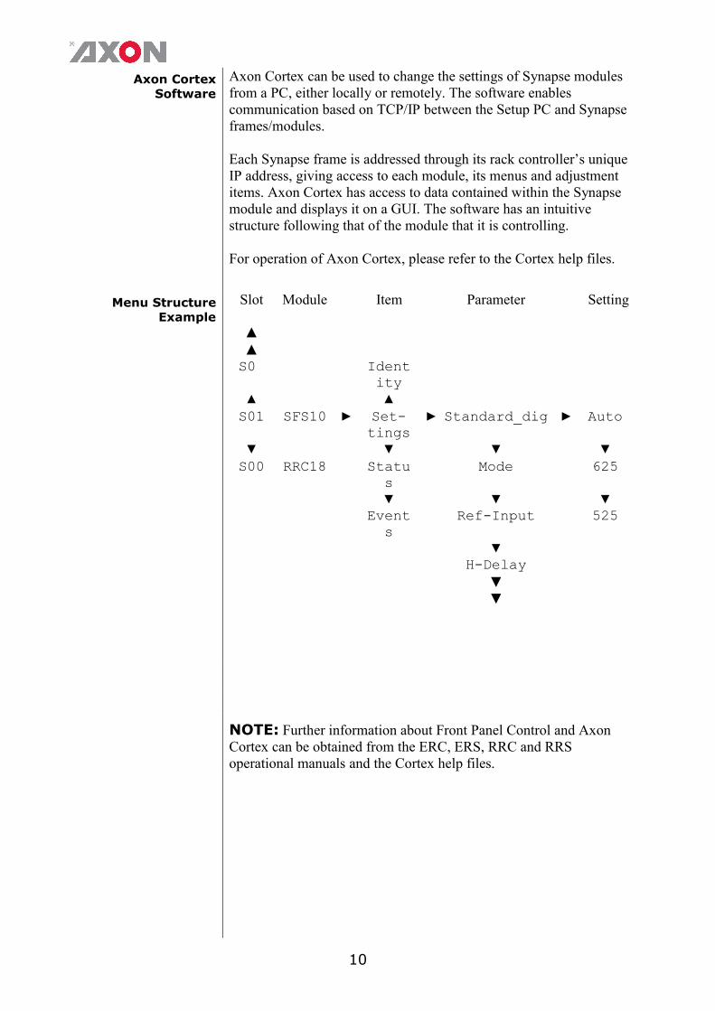
Axon Cortex can be used to change the settings of Synapse modules from a PC, either locally or remotely. The software enables communication based on TCP/IP between the Setup PC and Synapse frames/modules. Each Synapse frame is addressed through its rack controller’s unique IP address, giving access to each module, its menus and adjustment items. Axon Cortex has access to data contained within the Synapse module and displays it on a GUI. The software has an intuitive structure following that of the module that it is controlling. For operation of Axon Cortex, please refer to the Cortex help files.
Menu Structure Example
Slot Module Item Parameter Setting
▲ ▲ S0 Ident
ity
▲ ▲ S01 SFS10 ► Set-
tings ► Standard_dig ► Auto
▼ ▼ ▼ ▼ S00 RRC18 Statu
s Mode 625
▼ ▼ ▼ Event
s Ref-Input 525
▼ H-Delay
▼ ▼
NOTE: Further information about Front Panel Control and Axon Cortex can be obtained from the ERC, ERS, RRC and RRS operational manuals and the Cortex help files.

11
4 The GNS600 card
Introduction The GNS600 is a 3G, HD and SD SDI SCTE104 inserter with SDI inputs outputs. SCTE104 information present in the SDI signal can be transcoded and inserted into the main 3G, HD or SD SDI signal. The GNS600 can insert data from both the Ethernet and SDI domain into lines in the SDI domain or insert a user defined cue on a preset base. The GNS600 can insert or decode SMPTE-2010 packets containing SCTE104 Digital Program Insertion (DPI) messages to/ from VANC. Transcode between SCTE104 HD and SCTE104 SD data is also possible. The card will decode the SCTE104 DPI messages (contained on any or only user specified lines) and monitor for specific (user defined) content and trigger the appropriate GPO or pass the DPI message content to other control systems via Ethernet connection. Messages received as SCTE104 packets will be treated as status changes and may be logged by an external system. The card will encode the cues received from local GPI, or via ACP as predefined (user configurable) SCTE104 DPI Operation messages packets. The card will also format information, received as Ethernet packets from external control systems, and inject this SCTE104 messages. Note: SCTE104 specifies availability of user defined operation names on ID C000-FFFE, these are supported on this card. This data embedding is transparent to embedded audio that might be present in the SDI domain. The card has preset configurations and these can be recalled on the reception of appropriate SCTE104 DPI messages, via local GPIs or manual control via ACP Secondly, the GNS600 can function as a standalone card that enables Teletext and subtitle data, to be encoded onto a program feed; This card is able to insert Newfor (WST-B, OP47-SDP and S2031) protocol in VBI/VANC. Another function of this card is bridging data, such as VBI or VANC information. When this data is present in the SDI signal can be transcoded and inserted into the main SDI signal. For example, line 7 of the SDI input can be inserted into line 335 of the SDI output signal. This line exchange is transparent to embedded audio that might be present in the SDI domain. The complete insertion table is placed below. Typically, this functionality has been available in 1RU box, single PSU solutions from specialist subtitling companies, so the modular GNS600 should save on rack space, increase reliability and be more cost effective, certainly in multi-channel applications.
12
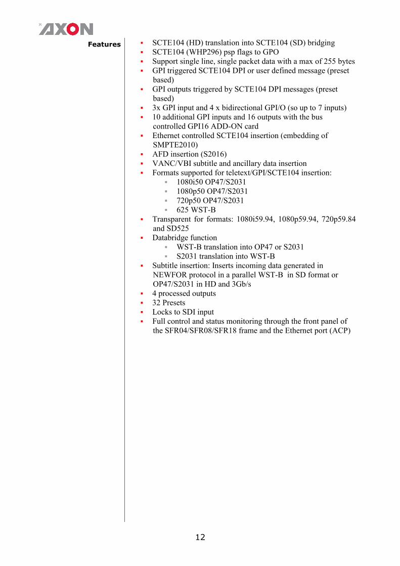
Features
SCTE104 (HD) translation into SCTE104 (SD) bridging SCTE104 (WHP296) psp flags to GPO Support single line, single packet data with a max of 255 bytes GPI triggered SCTE104 DPI or user defined message (preset
based) GPI outputs triggered by SCTE104 DPI messages (preset
based) 3x GPI input and 4 x bidirectional GPI/O (so up to 7 inputs) 10 additional GPI inputs and 16 outputs with the bus
controlled GPI16 ADD-ON card Ethernet controlled SCTE104 insertion (embedding of
SMPTE2010) AFD insertion (S2016) VANC/VBI subtitle and ancillary data insertion Formats supported for teletext/GPI/SCTE104 insertion:
1080i50 OP47/S2031 1080p50 OP47/S2031 720p50 OP47/S2031 625 WST-B
Transparent for formats: 1080i59.94, 1080p59.94, 720p59.84 and SD525
Databridge function WST-B translation into OP47 or S2031 S2031 translation into WST-B
Subtitle insertion: Inserts incoming data generated in NEWFOR protocol in a parallel WST-B in SD format or OP47/S2031 in HD and 3Gb/s
4 processed outputs 32 Presets Locks to SDI input Full control and status monitoring through the front panel of
the SFR04/SFR08/SFR18 frame and the Ethernet port (ACP)

13
Conversion Abilities
The GNS600 card is able to switch and convert the following video formats: Note 1 : Input format = 3Gb/s, HD, SD SDI input-format selected with setting S2010Emb-104Src, which sets the SDI source of the S2010/SCTE104. Note 2 : Output = 3Gb/s, HD, SD SDI input-format selected with setting Input-Select, which sets the SDI source of the SDI output. (SDI-source of the SDI Output) Note 3: Different field-rates on inputs cannot be mixed, empty squares represent NO OPERATION.
Output
FUNCTIONS
57
6i5
0(6
25
)
48
0i5
9.9
4(5
25
)
72
0p
50
72
0p
59
.94
10
80
i50
10
80
i59
.94
10
80
p5
0
10
80
p5
9.9
4
In
pu
t
576i50(625) Bridge/ Swap
SCTE104 to/from
SCTE104 SD to HD, WST-B
to OP47*/ S2031
SCTE104 SD to HD, WST-B
to OP47*/ S2031
SCTE104 SD to HD, WST-B
to OP47*/ S2031
480i59.94 (525) Bridge/ Swap
SCTE104 to/from
SCTE104 SD
to HD
SCTE104 SD to HD
SCTE104 SD to HD
720p50
SCTE104 HD to SD, OP47*/
S2031 to WST-B
Bridge/ Swap SCTE104 to/from, OP47*
to/from S2031
Bridge/ Swap SCTE104 to/from, OP47*
to/from S2031
Bridge/ Swap SCTE104 to/from, OP47*
to/from S2031
720p59.94 SCTE104 HD
to SD
Bridge/ Swap SCTE104 to/from
Bridge/ Swap
SCTE104 to/from
Bridge/ Swap SCTE104 to/from
1080i50
SCTE104 HD to SD, OP47*/
S2031 to WST-B
Bridge/ Swap SCTE104 to/from, OP47*
to/from S2031
Bridge/ Swap SCTE104 to/from, OP47*
to/from S2031
Bridge/ Swap SCTE104 to/from, OP47*
to/from S2031
1080i59.94 SCTE104 HD
to SD
Bridge/ Swap SCTE104 to/from
Bridge/ Swap
SCTE104 to/from
Bridge/ Swap SCTE104 to/from
1080p50
SCTE104 HD to SD, OP47*/
S2031 to WST-B
Bridge/ Swap SCTE104 to/from, OP47*
to/from S2031
Bridge/ Swap SCTE104 to/from, OP47*
to/from S2031
Bridge/ Swap SCTE104 to/from, OP47*
to/from S2031
1080p59.94 SCTE104 HD
to SD
Bridge/ Swap SCTE104 to/from
Bridge/ Swap
SCTE104 to/from
Bridge/ Swap SCTE104 to/from
Effective on lines Field 1 Field 2
576i50(625) 7..22 320..335
480i59.94(525) 11..21 274..284
720p50 8..25
720p59.94 8..25
1080i50 8..20 571..583
1080i59.94 8..20 571..583
1080p50 7..41
1080p59.94 7..41

14
Block schematic
INTERNAL SYNAPSE BUS
GNS600
RACK CONTROLLER
EQ
PRESET BASEDVANC DATA:
DECODING GENERATION
ENCODINGDATA TRANSCODER
EQAUTOPHASEROFFSET DELAY
µP
EQ
VANC DATAEMBEDDER
AUTOPHASEROFFSET DELAY
VANC DATADE-EMBEDDER
VANC DATADE-EMBEDDER
VANC DATAENCODER
VANC DATADECODER
ETHERNETPACKETIZER
DE-PACKETIZER GPI OUT
MAPPING
VANC DATADE-EMBEDDER
GPI INMAPPING
1 2
GPI16 CONTROL I/O
EQVANC DATA
DE-EMBEDDER
SCTE104 GENERATOR
PLL
VANC DATA MUX

15
5 Settings Menu
Introduction The settings menu displays the current state of each GNS600 setting and allows you to change or adjust it. Settings can be changed using the front panel of the Synapse frame (SFR18, SFR08 or SFR04) or with Cortex. Also the SCP08 control can be used. Please refer to chapter 3 for information on the Synapse front panel control and Cortex. Note: All items preceded with a #-sign are part of the presets.
VIDEO
Input-Select With this item you can decide which of the 4 inputs is used. Choices are SDI-1, SDI-2, SDI-3 or SDI-4. Default is SDI-1.
Lock-Mode Lock-Mode is default set to Input.
Ref-Type
Sets the type of incoming reference. Can be either Bi-Level or Tri-Level. Default is Bi-Level.
P60-P50_Sync
With this setting you can choose to synchronize each one frame or each two frames. Default is One Frame. The two-frame-synchronize mode only works for 720p60, 720p50, 1080p50 and 1080p60 standards
Out-Frmt
With Out-Frmt you can set what the output should be. This setting is only used for the delay options. This will not up/down/cross convert your input signal. Possible settings are:
1080p60, 1080p50 1080i60, 1080i50 1080p30, 1080p25, 1080p24, 1080p24psf 720p60, 720p50 SD525, SD625 Auto (default, selects the input format automatically conform
what has been detected)
IO-Map With this setting you can select the 3Gb/s mapping in case the input format is 1080p50 or 1080p60. Can be manually set to Level A or Level B. You can also choose to set it to Auto (default), in which case the card will automatically detect whether the input is Level A or Level B

16
Input_Loss Input_Loss determines what the outputs are in case of lost input: Freeze: a capture of the last good field or frame. Colorbar: a color bar Zoneplate: a zone plate Black: a black output. Grey: a grey output. Green: a green output. No-SDI-Out: no SDI carrier (completely mute output)
The default setting is freeze.
Test-Pattern With this setting you can enable a test pattern as frame synchronizer output on the outputs. Can be a Colorbar or a Zoneplate. By default is set to Off.
FS_Gen-Speed This sets the speed of the colorbar or zoneplate generator on a scale from 0 (still) to 15 (fast). By default it is set to 1.
S352_Insert S352_Insert enables (on) the Video Payload Identifier insertion in the HANC space. Default is on. This packet is required for 3G standards. In HD 1080i for ATC-LTC transparency the user may switch it off to pass the ATC-LTC HANC packet on line 10.
DELAY
Dly_Frmt_Prst With Dly_Frmt_Prst you can edit the delay values for the various video formats. This works as presets. All settings with a #-prefix are part of the preset. Set this to the video format for which you want to adjust the delay of the synchronizer. This setting is only used to display the correct delay settings. Possible settings are:
1080p60, 1080p50 1080i60, 1080i50 1080p30, 1080p25 1080p24, 1080p24sf 720p60, 720p50 SD525, SD625
#F-delay_1 F-Delay sets the amount of delayed Frames. The available range is from 0 to 125 frames (dependant on the video format). Default is 0F. The preset master for this is Dly_Frmt_Prst, hence the ‘#’-prefix.
#V-delay_1 V-Delay setting allows adjustment of the vertical phase of the output signal with respect to the selected reference input. The V-Delay setting gives a delay in addition to the reference timing. For example: if V-Delay is set to 10 TV HD lines, the output signal will be delayed by reference timing + 10 TV HD lines. The signal is delayed (advanced) with respect to the phase of the reference signal. The
17
available range is from 0 to a maximum of 1125 lines (dependant on the video format). The default setting is 0ln. The preset master for this is Dly_Frmt_Prst, hence the ‘#’-prefix.
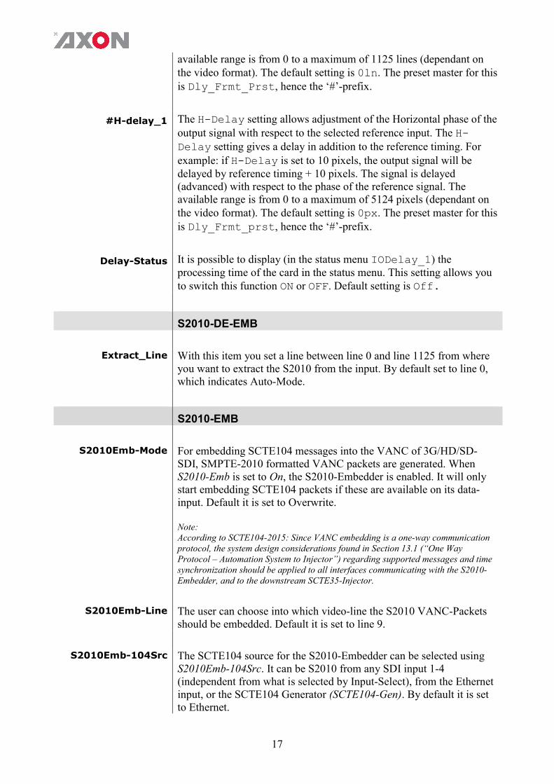
#H-delay_1 The H-Delay setting allows adjustment of the Horizontal phase of the output signal with respect to the selected reference input. The H-Delay setting gives a delay in addition to the reference timing. For example: if H-Delay is set to 10 pixels, the output signal will be delayed by reference timing + 10 pixels. The signal is delayed (advanced) with respect to the phase of the reference signal. The available range is from 0 to a maximum of 5124 pixels (dependant on the video format). The default setting is 0px. The preset master for this is Dly_Frmt_prst, hence the ‘#’-prefix.
Delay-Status It is possible to display (in the status menu IODelay_1) the processing time of the card in the status menu. This setting allows you to switch this function ON or OFF. Default setting is Off.
S2010-DE-EMB
Extract_Line
With this item you set a line between line 0 and line 1125 from where you want to extract the S2010 from the input. By default set to line 0, which indicates Auto-Mode.
S2010-EMB
S2010Emb-Mode
For embedding SCTE104 messages into the VANC of 3G/HD/SD-SDI, SMPTE-2010 formatted VANC packets are generated. When S2010-Emb is set to On, the S2010-Embedder is enabled. It will only start embedding SCTE104 packets if these are available on its data-input. Default it is set to Overwrite. Note: According to SCTE104-2015: Since VANC embedding is a one-way communication protocol, the system design considerations found in Section 13.1 (“One Way Protocol – Automation System to Injector”) regarding supported messages and time synchronization should be applied to all interfaces communicating with the S2010-Embedder, and to the downstream SCTE35-Injector.
S2010Emb-Line
The user can choose into which video-line the S2010 VANC-Packets should be embedded. Default it is set to line 9.
S2010Emb-104Src
The SCTE104 source for the S2010-Embedder can be selected using S2010Emb-104Src. It can be S2010 from any SDI input 1-4 (independent from what is selected by Input-Select), from the Ethernet input, or the SCTE104 Generator (SCTE104-Gen). By default it is set to Ethernet.

18
AliveReq When AliveReq is set to On, an alive-request packet is sent periodically
to ensure that the connection from the S2010-Embedder to the Injector stays active. Only when this feature is enabled, and no new SCTE104-Packets are available at the data-input of the S2010-Embedder, within the time set with AliveReq-Beat, an alive-request packet is generated and embedded into the VANC of the SDI Output. The beat-time is set with AliveReq-Beat. When incoming SCTE104 packets to the S2010-Embedder are detected within the AliveReq-Beat, the alive-request packet-generation is discarded. The alive-request packet generator is part of the S2010-Embedder. Default it is set to On. Note: According to SCTE104-2010: An alive-request message shall be sent at least once every 60 seconds. If the messages fail to arrive, then the receiving Injector shall notify its PAMS or a human operator that communications may be lost (this message is also known as Alive or Heartbeat).
AliveReq-Beat
The beat-time for sending alive-request packets is set with AliveReq-Beat. The alive-request packet generator is part of the S2010-Embedder. Default it is set to 30 seconds.
SCTE104/S2010 The GNS600 has extensive SCTE104/S2010 functionalities. The following schematics gives a visual overview on how the data is handled:
Analyzer-104Src
The source for the SCTE104-Analyzer can be selected using Analyzer-104Src. It can be SCTE104 from any SDI input (SDI-1 to SDI-4) (independent from what is selected by Input-Select), from the Ethernet input (Ethernet), or the SCTE104 Generator (SCTE104-Gen). By default it is set to SDI-1.
19
Analyzer-104Loss This setting defines the way the SCTE104 analyzer should behave, in case the source of the analyser is loss. When set to Off, the status-items of the analyser will change to its default state after a timeout of 60 seconds when no new SCTE104 message is received. When set to Freeze, the � nalyser status-items will hold its last known value. Default it is set to Off.
SCTE104Control With this setting you decide whether you want to manually change the presets, or change presets via the GPI contacts (GPI-A). Default is manual.
SCTE104PrstAct With this item you can manually change the currently active preset. Can be any preset between 1 and 32. By default it is set to 1. All menu settings that are preceded with a ‘#‘-prefix are part of the preset.
SCTE104PrstEdit Here you can select which of the selectable presets you want to edit. Changing this will not change the active preset, unless the currently active preset is the same you are going to edit. All menu settings that are preceded with a ‘#‘-prefix are part of the preset.
SCTE104PrstView
With this setting set to Follow Active, the edit preset settings will follow the active preset when the active preset is changed. This to avoid confusion when changing the active. Set to Independent the edit preset will not automatically follow active preset changes. By default set to Follow Active.
#SCTE104PrstName Sets/displays the name of the currently displayed preset.
#SCTE104Gen-Mode
This setting enables the SCTE104 Packet-Generator and defines the way SCTE104 packets are generated. The SCTE104 Packet-Generator is capable of generating various SCTE104-packets. This can be useful for manually overwriting the Injector if the Automation System fails, or if the Injector is not in the expected state. It also can function as test-generator for operability evaluations. The SCTE104 Generator can be set to Off, One-Shot, Interval and Continuous. Off disables the packet generator. One-Shot sends only one packet when the setting SCTE104OneShot is toggled. When Interval is chosen the generator generates packets with a defined interval set with SCTE104Interval. When Continuous is selected the SCTE104 packets are generated continuously (every single video frame).
SCTE104OneShot
When SCTE104Gen-Mode is set to One-Shot, this setting forces the SCTE104-Generator to generate a single packet. It should be manually set to On and it will automatically reset to Off again (auto toggle function).

20
#SCTE104Interval
When SCTE104Gen-Mode is set to Interval, this setting selects the time-interval at which SCTE104-packets are generated. The interval can be selected from 0 to 100 seconds, in steps of 1 second. When SCTE104Interval is set to 0 seconds, the time-interval is disabled and SCTE104-packets are generated continuously (every single video frame).
#SCTE104Message
This setting selects the different types of messages which can be generated by the SCTE104 Packet Generator. It can be set to Splice Req, PSP DOG Req, PSP Flags Req or Sub Timing Req. The Splice Request message is fully configurable using the SCTE104-Generator. Each splice request message can be configured to any of the standard types (Reserved, Start-Normal, Start-Immediate, End-Normal, End-Immediate, or Cancel). The other fields within the splice request message (like Program ID, Pre-Roll, etc.) are fully configurable. The PSP DOG Request message contains information to select, position and activate a down-stream Digital On-screen Graphics (DOG). The main part of the PSP DOG Request message is pre-defined, where the PSP DOG Active field is configurable. The PSP DOG Request pre-defined data is:
opID: 0xC0C3 data_length: 0x0006 psp_dog_tag: 0x444F4753 (4 byte ASCII text string: DOGS) psp_dog_version: 0x01 (WHP296 revision Nov/Dec 2015)
The PSP Flags Request message contains flags to identify item type (e.g. Programme, Trail etc.) and any processing present. The main part of the PSP Flags Request message is pre-defined, where the PSP Flags Type and PSP Flags Prog fields are configurable. The PSP Flags Request pre-defined data is:
opID: 0xC0C2 data_length: 0x0008 psp_flags_tag: 0x464C4753 (4 byte ASCII text string: FLGS) psp_flags_version: 0x00 (WHP296 revision June 2015)
The Sub Timing Request message contains information to enable a down-stream device to re-time (live) subtitles that are carried in the same signal. The main part of the Sub Timing Request message is pre-defined, where the Sub Timing Control and Sub Timing Length fields are configurable. The Sub Timing Request pre-defined data is:
opID: 0xC0C0 data_length: 0x0008 sub_timing _tag: 0x53554254 (4 byte ASCII text string: SUBT) sub_timing_version: 0x01 (WHP296 revision Nov/Dec 2015)
Note:

21
The PSP DOG Request, PSP Flags Request and Sub Timing Request message protocols are based on BBC White Paper WHP296 “Programme related metadata in SDI VANC”.
#AS-Index
The AS-Index (Automation System Index) uniquely identifies the source of the message, since it is possible to have several automation systems active at once. The number ranges from 0 to 255. If the index is not required it can be set to zero. This setting also defines the AS-Index field of the alive-request packet-generator within the S2010-Embedder.
#DPI-PID-Index
DPI-PID-Index (Digital Program Insertion Packet Identifier Index) allows a given Automation System to direct messages to a specific MPEG program in a specific Transport Stream (TS). It specifies the PID (Packet Identifier) that a resulting SCTE35 message would appear in a TS. The number ranges from 0 to 65535. If the index is not required it can be set to zero. This setting also defines the DPI-PID-Index field of the alive-request packet-generator within the S2010-Embedder.
#TimeType
With this setting the Time-Type for multiple-operation messages can be selected. It can be set to: Off, UTC, VITC or GPI. When set to Off, it indicates that there is no time required and the remainder of the structure is empty. When UTC is selected, it indicates that the time-field of the multiple-operation message is setup for UTC time. When set to UTC, the time-field in the SCTE104 Packet Generator is pre-defined and set to zero. When VITC is selected it means that the time-field is setup for SMPTE VITC timecode. Selecting GPI indicates that a GPI input is being used to trigger a DPI splice-info-section.
#VITC-Hours
If TimeType is set to VITC, this field encodes the hour of the day in 24-hour time. Values range from 0 to 23 in steps of 1.
#VITC-Minutes
If TimeType is set to VITC, this field encodes the minute of the hour. Values range from 0 to 59 in steps of 1.
#VITC-Seconds
If TimeType is set to VITC, this field encodes the seconds of the minute. Values range from 0 to 59 in steps of 1.
#VITC-Frames
If TimeType is set to VITC, this field encodes the frame within the current second. The range of values changes based upon whether the system is 30Hz or 25Hz based video and whether or not the frame rate is actually divided by 1.001. Typical values are 0 to 29 for 30 or
22
30/1.001 Hz systems, and 0-24 for 25 Hz systems. Values range from 0 to 59 in steps of 1.
#GPI-Number
If TimeType is set to GPI, this setting indicates the GPI to use for triggering the insertion of the DPI splice-info-section. Its value can be set from 0 to 255.
#GPI-Edge
If TimeType is set to GPI, this setting defines the edge to use to trigger message processing. Open->Closed indicates a transition from open to close. Closed->Open indicates a transition from closed to open.
#SpliceInsType
When SCTE104Message is set to Splice Request, the SCTE104-Generator generates a splice-request packet. The splice-insert-type (SpliceInsType) of the splice request packet defines the type of insertion operation desired. The different types are: Reserved, Start Normal, Start Immediate, End Normal, End Immediate and Cancel.
Reserved Start Normal sections occur at least once before a splice
point. It is recommended that sufficient pre-roll time is given by the Automation System.
Start Immediate sections may come once at the splice point’s exact location.
End Normal sections come to terminate a splice done without a duration specified. They may also be sent to ensure a splice has terminated on schedule.
End Immediate sections come to terminate a current splice before the splice point, or a splice in process earlier than expected.
Cancel sections come to cancel a recently sent Start Normal section.
#SpliceEventID
The SpliceEventID field is a unique ID used to determine whether different messages refer to the same event/splice (for example a Start/End pair). The identifier is a 32-bit integer and usually is incremented for each event.
#SpliceProgramID
This value should provide a unique identification for a viewing event within the service. This is a 16-bit field and has to be unique during a time-interval of 24 hours.
#SplicePreRoll
The SplicePreRoll 16-bit field defines the insert point: the time from the moment of generation of the message till the moment of insert, in milliseconds. This field is only used by the Injector when SpliceInsType is set to Start Normal or End Normal. The default value is 8000ms.
Note: According to SCTE104-2015: A minimum non-zero value of pre-roll time shall be 4000ms.
23
#SpliceBreakDur
The SpliceBreakDur field specifies the duration of the insertion (commercial break) in tenths of seconds. If zero, the Injector will not set a duration and makes the parameter inactive. This field is only used by the Injector when SpliceInsType is set to Start Normal or Start Immediate, otherwise it can be set to zero.
#SpliceAvailsNum
This setting indicates which avail within the program is currently being described. It can be set from 0 to 255. If it is set to zero, then also SpliceAvailsExp should be set to zero.
#SpliceAvailsExp
This setting indicates how many avails to expect within the program currently being described. It can be set from 0 to 255. If set to zero, then then SpliceAvailnum has no meaning and should be set to zero.
#SpliceAutoRtFlg
This setting can be set to Off or On. When set to On, it denotes that the break duration, set by #SpliceBreakDur, shall be used by the splicing device. When set to Off, the break duration field, if present, is not required to end the break because a new splice_insert command will be sent to end the break. In this case the presence of the break duration field acts as a safety mechanism in the event that a splice_insert() command is lost at the end of a break. This field is only used by the Injector when SpliceInsType is set to Start Normal or Start Immediate.
#SubTimingCntr When SCTE104Message is set to Sub Timing Request, the SCTE104-Generator generates a sub timing request packet. The sub timing control field (SubTimingCntr) within the sub timing request packet defines how subtitles in a down-stream device should be re-timed. It can be set to: Off, Remove or Subtract. When set to Off, it disables the delay control and the default delay of the down-stream device is used. If set to Remove it removes the default compensating delay. If set to Subtract, and a down-stream device is capable of dynamically adjust the compensating delay, it will use sub timing length (SubTimingLngth) to modify the default compensating delay of the down-stream device. It subtract the SubTimingLngth from the default compensating delay. If SubTimingLngth is greater than the default value, the down-stream device shall limit the resulting modified value to 0ms.
#SubTimingLngth When SubTimingCntr is set to Subtract, this field defines the subtract value. This value is used to modify the default compensating delay of the down-stream device. It is a 16-bit field which specifies a time in units of 1ms.
#PSP-FlagsType When SCTE104Message is set to PSP Flags Request, the SCTE104-Generator generates a psp flags request packet. The PSP

24
Flags Type field (PSP-FlagsType) within the psp flags request packet identifies the item type. It can be set to: Undefined, Programme, Trail, Interstitial, Commercial or Reserved.
#PSP-FlagsProg The PSP-FlagsProg field within the psp flags request packet is a 16-bit field that contains a number of programme related indicators. Each bit of the 16-bit word can be set to 0 or 1. Below is a description of every bit.
b0 (LSB) 1 = up-converted programme b1 1 = audio translation indicator b2 1 = live programme b3 1 = end credit squeeze active b4 1 = blanking platform 1 active b5 1 = blanking platform 2 active b6 1 = audio watermark present b7 1 = video watermark present b8 1 = audio has been processed b9 1 = trailer selection trigger present b10 1 = network indicator b11 1 = opt-out flag b12 1 = audio description present b13 1 = second audio present b14 reserved b15 reserved
#PSP-DOGActive When SCTE104Message is set to PSP DOG Request, the SCTE104-Generator generates a psp dog request packet. The PSP DOG Active field (PSP-DOGActive) within the psp dog request packet contains the DOG selection. It can be set from 0 to 127. If it is set to zero it means that the DOG is not active.
S2016
S2016-Insert You can turn S2016 (AFD) insertion on or off for channel A. Default is Off.
S2016-Line With this setting you select a line in the VBI to where the AFD (SMPTE 2016) data should be written. Lines 0 till 31 are selectable. By default it is set to line 11.
S2016-Aspect 4:3 and 16:9
S2016-Data With thise setting you can select which AFD you want to insert. Default is AFD0.

25
S2031-OP47- WST
Decoder-Source The GNS600 can be set to different functions. One of them is the bridging and insertion of OP47, S2031 or WST-B data. This item selects the input which will be used as input for the Ancillary data. We can decode ANC data from one of the four SDI inputs or through Ethernet. Via Ethernet we are able to accept data compatible with Newfor protocol.
S2031-OP47-Dec This will be used in case of HD. The choice can be made between Auto mode and Manual mode. In manual Mode there is the choice between decoding of S2031 and OP47. In SD the card automatically switches to WST-B.
S2031-OP47-Enc This is the encoding format of S2031 or OP47 in HD
S2031Emb-Line The user can choose into which video-line of the SDI output the S2031 VANC-Packets should be embedded. Default it is set to line 8.
OP47Emb-Line The user can choose into which video-line of the SDI output the OP47 VANC-Packets should be embedded. Default it is set to line 8.
WST-Inserter WST-B inserter on or off.
S2031-WST-def WST-B packets inside the S2031 normally have a line number where the WST-B packets should be inserted in SD. When these line numbers are missing, we need to insert a line number to comply with the standard. This item will let you set the line number which can be inserted when the line number of the original packets are missing. This is the line umber for the first WST-B packet. If there are multiple packets they will be sequentially numbered.

26
GPI MODE
GPI_A-Mode
Selects the mode for the corresponding GPI pool. Possible settings are: Prio: Each contact triggers another value, so values are one-hot
encoded. Prio_latched: This mode functions like Prio Mode, but the
card latches the value. Each contact triggers another value, so values are one-hot encoded. Use this mode when using pushbuttons.
Binary: Values are coded in a binary fashion, with code “0000000” coding for a starting value of 1, as can be seen in the GPI status items.
Please refer to ‘Appendix 1: GPI’s explained’ for a more elaborate explanation of the GPI settings and status items.
GPO_A-Mode~ GPO_D-Mode
Set the mode of output pool GPO-A to GPO-D. Possible options are Prio or Binary. Default is Prio Prio: Pool value is translated to contacts in priority mode. E.g. if
the pool value is '3', the 3rd contact that is assigned to pool GPO-A is set to active.
Binary: Pool value is translated to contacts in binary mode. E.g. if the pool value is '3', both the 1st and 2nd contacts that are assigned to pool GPO-A to GPO-D are set to active.
GPO_A-Func~ GPO_D-Func
Assign a function to output pool GPO-A to GPO-D. Possible options are Off and Sub_Timing_Ctrl. Default is Off Off: No function; the GPO-A pool value is set to 0. Sub_Timing_Ctrl: Binary function senstitive to SCTE104
WHP296 Subtitle Timing Request packets. When a SCTE104 WHP296 Subtitle Timing Request packet is encountered where: property <Timing Control> equals <Off>: GPO-A to GPO-D
pool value is set to '0' property <Timing Control> equals <Remove> : GPO-A to
GPO-D pool value is set to '1' The Sub_Timing_Ctrl function is indifferent to any other values. Other bits which can be assigned are psp_flags_prog - A 16 bit field that contains a number of programme related indicators as described below Bit number
b0 (LSB) 1 = up-converted programme b1 1 = audio translation indicator b2 1 = live programme b3 1 = end credit squeeze active b4 1 = blanking platform 1 active b5 1 = blanking platform 2 active b6 1 = audio watermark present

27
b7 1 = video watermark present b8 1 = audio has been processed b9 1 = trailer selection trigger present b10 1 = network indicator b11 1 = opt-out flag b12 1 = audio description present b13 1 = second audio present b14 1 = network alert standby b15 1 = network alert active 4
GPI_A-Take
Selects a take contact for the corresponding GPI pool. Possible settings are: Off: No take contact is defined, and values on the GPI contact are
taken instantly. Contact_1 ~ Contact_7: The selected contact is used as a
Take command for the corresponding pool. Closing the selected contact results in the card latching the value provided on the selected contacts for that pool.
Please refer to ‘Appendix 1: GPI’s explained’ for a more elaborate explanation of the GPI settings and status
Contact_1~Contact7 In this card it is possible to make the 7 available GPI contacts part of GPI-A pool that can control the presets. You can also choose to not use the corresponding GPI at all by setting it to Off. Please refer to ‘Appendix 1: GPI’s explained’ for a more elaborate explanation of the GPI settings and status items.
TELETEXT
Protocol The card can be used wih different functions. For this we need to tell the card if the Ethernet port is used for SCTE104, Newfor or AODB-protocol.
NF_init_Overrule NF_Init_Overule This setting adds the ability to overrule the Newfor Page Init commands for the second Newfor stream with the #Magazine and #Header-TU settings. Selections are Off or On. Default is Off.
SD_F1_Ln1 In this menu item you select which line is the first line of field 1 you want to edit in SD formats. You can choose line 7 till line 22 to edit. Can also be switched off in case you don’t want to edit any lines of field 1. Default line is line Off.
SD_F1_Ln2 In this menu item you select which line is the second line of field 1 you want to edit in SD formats. You can choose line 7 till line 22 to edit. Can also be switched off in case you don’t want to edit a second lines of field 1. Default line is Off.

28
SD_F1_Ln3 In this menu item you select which line is the third line of field 1 you want to edit in SD formats. You can choose line 7 till line to edit. Can also be switched off in case you don’t want to edit any lines of field 1. Default line is line Off.
SD_F1_Ln4 In this menu item you select which line is the fourth line of field 1 you want to edit in SD formats. You can choose line 7 till line 22 to edit. Can also be switched off in case you don’t want to edit a second lines of field 1. Default line is Off.
Active-Preset With this item you can manually change the currently active preset for the first service. Can be any preset between 1 and 6. By default it is set to 1. All menu settings that are preceded with a ‘#‘-prefix are part of the preset.
Edit-Preset Here you can select which of the 6 selectable presets for the first service you want to edit. Changing this will not change the active preset, unless the currently active preset is the same you are going to edit. All menu settings that are preceded with a ‘#‘-prefix are part of the preset.
#Enabled Enables or disabled the preset for the first service.
#Language For each subtitle service it is possible to define a default language. The language is set using control bits C12, C13 and C14. The possible languages for the HSI20 are: ■ 000-UK (default) ■ 001-DE ■ 010-SW/FI/HU ■ 011-IT ■ 100-FR ■ 101-PT/ES This setting sets the language for the first service.
#Magazine Each different language is normally transmitted on a separate page number, defined by the #Magazine and Header Tens and Units (#Header-TU) values. With this setting you set the magazine between 1 and 8 for the first service. Default is 8.
#Header-TU Here you define the language page header tens and units for the first service. Default is 88 (together with the default magazine value, making page 888).
#Stopper-TU This setting defines Stopper tens and units for the first service. Stoppers are generally required in a Teletext subtitling only environment to terminate the reception of a Teletext subtitle. Under
29
normal circumstances the reception of a Teletext subtitle is by the following Row0 transmission (#Row0- settings). Default is FE (together with the default magazine value, making page 8FE.
#Row0-Data This allows the user to define the content of the Teletext header row transmitted with the subtitle for the first service. The field data is in plain text format and can contain up to 32 characters. This can be used to insert audience monitoring information or channel identification information with the subtitles.
#Row0-C5 ~ #Row0-C11
With these items you set the Row Zero control bits for the first service: ■ C5: Newsflash bit, the page to be displayed requires boxing and
will be mixed with the video picture ■ C6: Subtitle bit, the page to be displayed requires boxing and will
be mixed with the video picture ■ C7: Suppress Header bit, the Row- will not be displayed with the
transmitted page. ■ C8: Update bit, used to indicate that the page content has changed
since the last transmission ■ C9: Interrupted Sequence bit, the transmitted but will not be
displayed by the decoder. ■ C10: Inhibit Display bit, The page is transmitted but will not be
displayed by the decoder ■ C11: Magazine Serial bit, when this is set, the pages in the
magazine will be transmitted in serial, not set indicates parallel transmission
#Dbl-Transmit When Double transmit is switched on each subtitle or Teletext page will be transmitted twice for the first service. This feature can improve quality in poor reception areas.
X31
X31-Enc-Cues With this setting you can enable or disable packet 31 cue insertion. Default is off.
X31-Enc-Ln Here you select into which line packet 31 should be encoded. Can be any line between 7 & 22 and 320 & 335. Default is line 18.
X31-Enc-Channel With this you can assign a specific channel number to the cue. A decoder can be set to a specific cue channel and ignore all others. Can be channels 8, 9, A (hex) or B (hex). Default is channel 8.
X31-Enc-Text Optional text which can be used as a reference to what the lines contain. Default is Axon X31 encoder.
30
X31-Enc-Address With this setting you can assign a specific address within the cue channel. A decoder is set up to “listen” to this specific address within the cue channel and ignore all others. The address range is from 00 till FF (hex).
X31-Enc-Input With this setting you select the encoder input, which can be set to manual or to GPI_Backpanel. Set to manual allows for encoding the ACP values of X31-Enc-GPIx instead of real GPI values. Set to GPI_Backpanel will use the real GPI values of the backpanel for encoding the X31 packets.
X31-Enc-GPI1 GPI1 value for encoding manual input (set to on or off). Only works when X31-Enc-Input is set to manual.
X31-Enc-GPI2 GPI2 value for encoding manual input (set to on or off). Only works when X31-Enc-Input is set to manual.
X31-Enc-GPI3 GPI3 value for encoding manual input (set to on or off). Only works when X31-Enc-Input is set to manual.
X31-Enc-GPI4 GPI4 value for encoding manual input (set to on or off). Only works when X31-Enc-Input is set to manual.
X31-Enc-GPI5 GPI5 value for encoding manual input (set to on or off). Only works when X31-Enc-Input is set to manual.
X31-Enc-GPI6 GPI6 value for encoding manual input (set to on or off). Only works when X31-Enc-Input is set to manual.
X31-Dec-Cues Enables or disables packet 31 decoding. Default is off.
X31_S2031-OP47 Here you select from what line packet 31 should be decoded. Can be any line between 7 & 22 and 320 & 335. Default is line 7.
X31-Dec-Channel With this you can select specific cue channel number which must be decoded. Can be channel 8, 9, A (hex) or B (hex). Default is channel 8.
X31-Dec-Address With this setting you can select a specific address within the cue channel which must be decoded. The decoder is set up to “listen” to this specific address within the cue channel and ignore all others. The
31
address range is from 00 till FF (hex).
X31-Dec-Loss
With this setting you can decide what should happen when the decoder looses a valid X31 cue signal. You can choose to Keep state (keep the current state), to set the GPI output to on (GPO on) or to set the GPI output to off (GPO off). Default is Keep state.
AODB
The data which is sent to the AODB slot is buffered. An SDI line nr is needed for proper insertion. When this SDI line is not assigned to the corresponding slot in the GNS600 it is discarded. For each frame, only one slot can insert data. A slot can insert data if its status is both on-air and data is present in its buffer. Lowered numbered slots have priority over higher numbered slots. If none of the slots can insert data, filling data is inserted if any of the slots is provisioned to do so. For inserting filling data the same rules apply; a slot has to be on-air, filling has to be enabled for that slot and lowered numbered slots have priority over higher numbered slots. When a slot can insert filling data, one packet is inserted in the lowest SDI line number assigned to the slot.
Ins-Ln-625-F1
In this menu item you select which line of field 1 you want to edit in SD625 formats. This works in a preset way. When you select a line in this item you will see what functions will be performed on that line in the menu-item #SD625-F1-Asgn. You can choose line 7 till line 22 to edit. Default line is 7.
#SD625-F1-Asgn
With this setting you can assign the SDI line you selected with Ins_Ln-625-F1 to a slot. Encoder slot presets define further behaviour for this line. Slots 0 till 7 are possible to select. In case auto is selected, OADB handler will auto assign the line it requested by OADB protocol to its first slot. #SD625-F1-Asgn is not only to address a hard line in SD but also to assign which line nr should be in wst-b lines in op47- cooked mode. SD lines which are set to be inserted into op47 should be assigned to the correct slot. Op47 data will be inserted on the HD line as defined by HD-F1-Ins-Ln and by HD-F2-Ins-Ln.
Encoder-Slot
A slot is a set of Lines and some extra behavior how these line should be handled. With the current release we can setup filling for each line which is not inserted on the current frame. You can select slots 0 till 7 here.
#Run-State Filling behavior on/off. Starts filling of each un-inserted line
#Time-Filling With this setting you decide a method you want to use for filling the
32
SDI wst or op-47 line data. Can be either filled with a packet 31 (PKt31) or packet 0 (PKt0). Default is PKt0.
Packet 31 filling is be done following the IDL format A as described in ETSI EN 300 708. The data channel and SPA can be manual filled by the settings below.
Packet 0 filling generates a wst-b page header on page 0xff. These packets are always send as serial teletext (C11 bit set). The #Fill-PCKT31-SPA is in this case miss-used to select the magazine number
#Filling-Method
Datachannel addressing is used when filling method is PKt31. Available values are 8 till 11 which are all IDL Format A data channels.
#Fill-PCKT31-DCG
Service packet address of the packet 31 filling lines. In case pckt0 filling is selected this is object is miss-used to select a magazine of the generated pck-0.
#Fill-PCKT31-SPA
A slot is a set of Lines and some extra behavior how these line should be handled. With the current release we can setup filling for each line which is not inserted on the current frame. You can select slots 0 till 7 here.
#Fill-PCKT0-Mag Sets the magazine number of a PCKT0 filling packet
#Dummies When dummies are on, the included VBI lines will be “filled” with “dummy” data for the first service. In order to keep the VBI line(s) active all the time. This is normally required if there is no sustaining Teletext service present in the VBI. This feature can improve quality in poor reception areas.
#DumHeader-TU Sets the dummy header tens and units for the first service. Default is FF (together with the default magazine value, making page 8FF).
NETWORK
Please note that TCP/IP networks for use with the SCTE104 standard are intended as strictly private, closed networks for the use of the Automation, Compression and Splicing systems. As a result, latency is not expected to be a major factor in system design.
PortNumber
The TCP portnumber where the GNS600 listens to. Default it is set to port 5167. The default value of 5167 conforms to the SCTE104-2015 standard.
Conn-Drop
Manually drop the SCTE104 TCP connection between automation and the GSN600 by setting this setting to On. Default it is set to Off. After dropping the connection the setting will be reset to Off.
33
Conn-Timeout
Default it is set to 0 seconds. If set to the default value of 0s the TCP keepalive feature is disabled. When this setting is set to a value greater than the default value of 0, TCP keepalive is enabled on new SCTE104 TCP connections. The TCP keepalive time (i.e. the interval between the last data packet sent and the first keepalive probe) is then set to the value of this setting. The values of the keepalive interval (i.e. the interval between sub sequential keepalive probes) is 5 seconds. The GNS600 will send 5 keepalive probes before the connection is considered dead and will be dropped.
SCTE104-Timeout
Default it is set to 0 seconds. If set to the default value of 0s the SCTE104 timeout watchdog is disabled. When this setting is set to a value greater than the default value of 0, the SCTE104 timeout watchdog is enabled on new and existing SCTE104 TCP connections. When the GNS600 has not received any SCTE104 packet on the TCP interface for the amount of seconds that the SCTE104-Timeout setting is set to, the connection is considered dead and will be dropped.
IP_Conf0 With this setting you can let the card obtain an IP address automatically via DHCP, or appoint a manual set IP address. When set to Disabled, the Ethernet port will be disabled. By default this setting is set to DHCP.
mIP0
When IP_Conf0 is set to manual, you can type in the preferred IP address here. By default it is set to 0.0.0.0
mNM0
With IP_Conf0 set to manual, with this setting you can set a Netmask. Default is 255.255.0.0
mGW0
With IP_Conf0 set to manual, this setting let you set a Standard Gateway. Default is set to 172.16.0.1
NetwPrefix0
With IP_Conf set to manual, this item lets you set a network mask prefix varying from 0 to 30 bit. The mNM0 network mask changes accordingly.

34
6 Status Menu
Introduction The status menu indicates the current status of each item listed below.
SDI-Input_1 ~
SDI-Input_4
These status items indicates the presence and format of a valid signal on SDI inputs 1 to 4. This is displayed as: 1080p60 1080p50 1080p30 1080p25 1080p24 1080p24sf 1080i60 1080i50 720p60 720p50 SD625 SD525 NA
SDI-Map_1 ~
SDI-Map_4
Displays whether the 3Gb/s input on inputs 1 to 4 is mapped as Level A or Level B. If the input is not 3Gb/s (1080p50 or 1080p60) this item indicates NA.
CRC-Stat_1 ~
CRC-Stat_4
Displays if there are CRC errors on inputs 1 to 4.
Ref Displays whether a correct reference is found (Present) or not (NA)
Ref-Format Displays the reference format. Can be one of the following: 1080p60 1080p50 1080p30 1080p25 1080p24 1080p24sf 1080i60 1080i50 720p60 720p50 SD625 SD525 NA

35
Locked-To Displays to what the card is locked: SDI1, SDI2, SDI3, SDI4, Ref, Freerun or Not Locked.
Output Displays the (last known) output format of the card. Displayed as listed under SDI_Input_1 ~ SDI_Input_4.
Output-Map This indicates the mapping of the (last known) output when the output format is 3Gb/s (1080p50 or 1080p60). Can be Level A or Level B. When the output format is not 1080p60 or 1080p50, this item indicates NA.
IODelay_1
Displays the I/O delay between the input and the output. Only indicated when Delay-Status is set to on.
SDI1S2010Stat ~ SDI4S2010Stat
These items indicates the status of the S2010 data on the SDI inputs. Can be OK, error or NA.
SDI1S2010LineSt ~ SDI4S2010LineSt
If S2010 data is detected on the SDI inputs, these items indicates the video line where the S2010 data is detected. Range is from 0 to 1125. Line 0 indicates that there is no S2010 line-detection possible or no S2010 data present on the SDI input.
SCTE104 ANALYZER STATUS
The source and behaviour of the following status items (preceded with ‘Ana’, SOM, MOM, SP and PSP prefix) is dependent on the Analyzer-104Src and Analyzer-104Loss settings.
AnaSCTE104Stat
This item indicates the status of SCTE104 messages detected on the input of the SCTE104 Packet Analyzer. Can be OK, Error or NA.
AnaSCTE104SOM A SCTE104 message can be send using as a single-operation-message (SOM) or a multiple-operation-message (MOM). This item indicates the status of the SOM, when detected. Can be OK, Error or NA.
AnaSCTE104MOM
A SCTE104 message can be send using as a single-operation-message (SOM) or a multiple-operation-message (MOM). This item indicates the status of the MOM, when detected. Can be OK, Error or NA.
AnaSOMALiveReq
This status item indicates the status of an Alive Request message, when detected. Can be OK, error or NA. The Alive Request is always wrapped in a SOM.

36
AnaMOMSpliceReq This status item indicates the status of a Splice Request message, when detected. Can be OK, error or NA. The Splice Request is always wrapped in a MOM.
AnaMomSubTimReq This status item indicates the status of a Sub Timing Request message, when detected. Can be Ok, Error, or NA. The Sub Timing Request is always wrapped in a MOM.
AnaMomPSPFlgReq This status item indicates the status of a PSP Flags Request message, when detected. Can be Ok, Error, or NA. The PSP Flags Request is always wrapped in a MOM.
AnaMOMPSPDOGReq This status item indicates the status of a PSP DOG Request message, when detected. Can be OK, error or NA. The PSP DOG Request is always wrapped in a MOM.
SOMOpIdStat
Displays the operation ID for single operation messages (SOM). The opID indicates what message is being sent. For SOM it only take values as Basic Request or Basic Response.
SOMMsgSizeStat Displays the size of the entire SOM structure in bytes.
SOMProtVerStat
Displays the protocol version being used for a SOM. Conform SCTE104-2015: The protocol version shall be zero (0x00). Non-zero values may be used by a future version of the standard to indicate structurally different messages.
SOMAsIndexStat Displays the AS-Index, which uniquely identifies the source of the SOM (since it is possible to have several automation systems active at once). The number ranges from 0 to 255 and shall be zero if the AS-Index is not required.
SOMMsgNrStat
Displays the message number of a SOM. It is used to identify an individual message. The range is from 0 to 255. This number must be unique for the life of a message.
SOMDPIPIDIndStat
Displays the Index to the DPI-PID of a single operation message (SOM). The number range is form 0 to 65535. If not required by the system the DPI-PID-Index shall be zero.
MOMMsgSizeStat Displays the size of the entire MOM structure in bytes.
MOMProtVerStat
Displays the protocol version being used for a MOM. As defined by SCTE104-2015: The protocol version shall be zero (0x00). Non-zero values may be used by a future version of the standard to indicate structurally different messages.
37
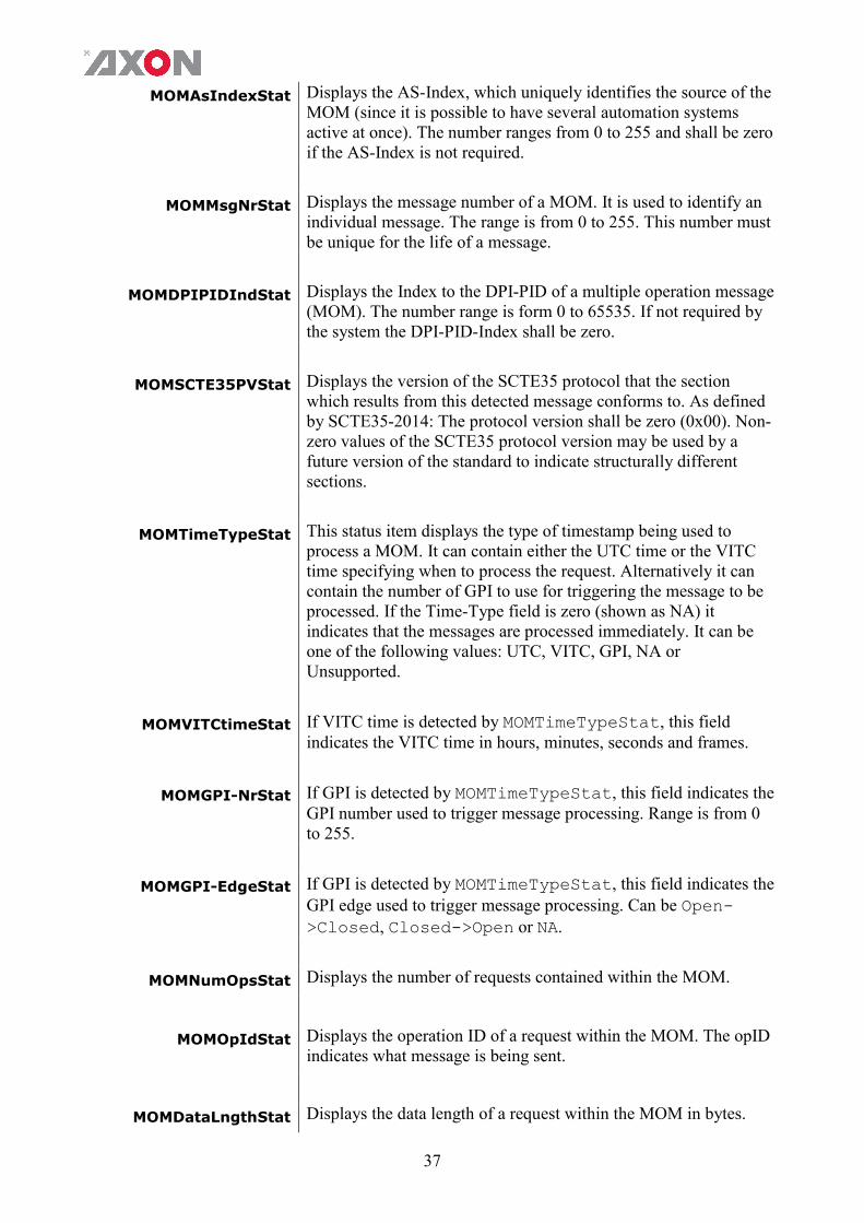
MOMAsIndexStat
Displays the AS-Index, which uniquely identifies the source of the MOM (since it is possible to have several automation systems active at once). The number ranges from 0 to 255 and shall be zero if the AS-Index is not required.
MOMMsgNrStat
Displays the message number of a MOM. It is used to identify an individual message. The range is from 0 to 255. This number must be unique for the life of a message.
MOMDPIPIDIndStat
Displays the Index to the DPI-PID of a multiple operation message (MOM). The number range is form 0 to 65535. If not required by the system the DPI-PID-Index shall be zero.
MOMSCTE35PVStat
Displays the version of the SCTE35 protocol that the section which results from this detected message conforms to. As defined by SCTE35-2014: The protocol version shall be zero (0x00). Non-zero values of the SCTE35 protocol version may be used by a future version of the standard to indicate structurally different sections.
MOMTimeTypeStat This status item displays the type of timestamp being used to process a MOM. It can contain either the UTC time or the VITC time specifying when to process the request. Alternatively it can contain the number of GPI to use for triggering the message to be processed. If the Time-Type field is zero (shown as NA) it indicates that the messages are processed immediately. It can be one of the following values: UTC, VITC, GPI, NA or Unsupported.
MOMVITCtimeStat If VITC time is detected by MOMTimeTypeStat, this field indicates the VITC time in hours, minutes, seconds and frames.
MOMGPI-NrStat
If GPI is detected by MOMTimeTypeStat, this field indicates the GPI number used to trigger message processing. Range is from 0 to 255.
MOMGPI-EdgeStat If GPI is detected by MOMTimeTypeStat, this field indicates the GPI edge used to trigger message processing. Can be Open->Closed, Closed->Open or NA.
MOMNumOpsStat Displays the number of requests contained within the MOM.
MOMOpIdStat
Displays the operation ID of a request within the MOM. The opID indicates what message is being sent.
MOMDataLngthStat Displays the data length of a request within the MOM in bytes.

38
SPInsTypeStat
This status item displays the type of insertion operation when a Splice Request message is detected by AnaMOMSpliceReq. Can be Reserved, Start-Normal, Start-Immediate, End-Normal, End-Immediate, Cancel or NA.
SPEventIDStat
Displays the Event-ID of a Splice Request message. The Event-ID is a unique ID used to determine whether different messages refer to the same event/splice (for example a Start/Stop pair). The identifier is a 32-bit field and usually increments for each event.
SPProgIDStat
This status items shows the Program-ID, it is a unique identification for a viewing event within the service. This is a 16-bit field and has to be unique during a time-interval of 24 hours
SPPreRollStat Displays the splice pre-roll time. It defines the insert point: the time from the moment of generation of the message till the moment of insert, in milliseconds
SPBreakDurStat Displays the duration of the commercial breaks in tenths of seconds. If it is zero the parameter is inactive.
SPAvailNumStat
This status item indicates which avail within the program is currently being described. Range from 0 to 255.
SPAvailsExpStat
This status item indicates how many avails to expect within the program currently being described. Range from 0 to 255. If zero, it indicates that SPAvailNumStat has no meaning.
SPAutoRtFlgStat Displays the auto return flag. Can be Off or On. When set to On, it denotes that the break duration, displayed by SPBreakDurStat, shall be used by the splicing device. When set to Off, the break duration field, if present, is not required to end the break because a new splice_insert command will be sent to end the break.
SubTimTagStat Displays the 4 byte ASCII text string to additional identify the Sub Timing Request data. The correct value read should be: 0x53554254 (=SUBT).
SubTimVerStat Displays the protocol version being used for a Sub Timing Request message, as defined by BBC WHP296. This field is used to indicate structurally different parameters by version numbers.
SubTimCntrlStat When a Sub Timing Request message is detected, SubTimCntrlStat displays how subtitles in a down-stream device should be re-timed. Can be Off, Remove or Subtract.

39
SubTimLngthStat When a Sub Timing Request message is detected and SubTimCntrStat status field indicates Subtract, this field (SubTimLngthStat) shows the subtract value. This value is used to modify the default compensating delay of the down-stream device.
PSPFlagsTagStat Displays the 4 byte ASCII text string to additional identify the PSP Flags Request data. The correct value read should be: 0x464C4753 (=FLGS).
PSPFlagsVerStat Displays the protocol version being used for a PSP Flags Request message, as defined by BBC WHP296. This field is used to indicate structurally different parameters by version numbers.
PSPFlagsTypeStat When a PSP Flags Request message is detected, PSPFlagsTypeStat contains flags to identify item type. Can be Undefined, Programme, Trail, Interstitial, Commercial, or Reserved.
PSPFlagsProgStat When a PSP Flags Request message is detected, PSPFlagsProgStat contains a number of programme related indicators. Each bit of the 16-bit word can be 0 or 1. Below is a description of every bit.
b0(LSB) 1 = up-converted programme b1 1 = audio translation indicator b2 1 = live programme b3 1 = end credit squeeze active b4 1 = blanking platform 1 active b5 1 = blanking platform 2 active b6 1 = audio watermark present b7 1 = video watermark present b8 1 = audio has been processed b9 1 = trailer selection trigger present b10 1 = network indicator b11 1 = opt-out flag b12 1 = audio description present b13 1 = second audio present b14 reserved b15 reserved
PSPDOGTagStat
Displays the 4 byte ASCII text string to additional identify the PSP DOG request data. The correct value read should be: 0x444F4753 (= DOGS).
PSPDOGVerStat
Displays the protocol version being used for a PSP DOG request message, as defined by BBC WHP296. This field is used to indicate structurally different parameters by version numbers.

40
PSPDOGActvStat
Displays which DOG is currently active. Range from 0 to 255. Zero means that the DOG is not active. Note: The PSP DOG Request message protocol is based on BBC White Paper WHP296. It contains information to select, position and activate a down-stream Digital On-screen Graphics (DOG).
SDI1S2016Stat ~ SDI4S2016Stat
Displays whether there is S2016 information available in the incoming SDI signal or not.
SDI1S2016LnSt ~ SDI1S2016LnSt
Displays in which line of the video the S2016 data is inserted. Can be any line between line 0 and line 1125.
SDI1S2016ARSt ~ SDI1S2016ARSt
Displays the Aspect ratio of the S2016 data. Can be 4:3 or 16:9 or Not available.
SDI1S2016Data ~ SDI1S2016Data
Displays which AFD value is be inserted by the S2016 inserter. Can be any AFD value between AFD0 and AFD15.
SDI1OP47Stat ~ SDI4OP47Stat
Indicates the status of the OP47 data on the SDI inputs. Can be OK or NA.
SDI1OP47F1LnSt ~ SDI4OP47F1LnSt
If OP47 (Field1) data is detected on the SDI inputs, these items indicate the video line where the OP47 data is detected. These items will also indicate OP47 line-detection for progressive video formats (frame based). Range is from 0 to 1125. Line 0 indicates that there is no OP47 line-detection possible or no OP47 data present on the SDI input.
SDI1OP47F2LnSt ~ SDI4OP47F2LnSt
If OP47 (Field2) data is detected in the second field of interlaced video formats, these items indicates the video line where the OP47 data is detected. Range is from 0 to 1125. Line 0 indicates that there is no OP47 line-detection possible or no OP47 (Field2) data present on the SDI input (for progressive formats).
SDI1S2031Stat ~ SDI4S2031Stat
Indicates the status of the S2031data on the SDI inputs. Can be OK or NA.
SDI1S2031F1LnSt ~ SDI4S2031F1LnSt
If S2031 (Field1) data is detected on the SDI inputs, these items indicate the video line where the S2031data is detected. These items will also indicate S2031line-detection for progressive video formats (frame based). Range is from 0 to 1125. Line 0 indicates that there is no S2031line-detection possible or no S2031data present on the SDI input.

41
SDI1S2031F2LnSt ~ SDI4S2031F2LnSt
If S2031 (Field2) data is detected in the second field of interlaced video formats, these items indicates the video line where the S2031 data is detected. Range is from 0 to 1125. Line 0 indicates that there is no S2031 line-detection possible or no S2031 (Field2) data present on the SDI input (for progressive formats). data is detected. Range is from 0 to 1125. Line 0 indicates that there is no S2031 line-detection possible or no S2031 (Field2) data present on the SDI input (for progressive formats).
SDI1WSTStat ~ SDI4WSTStat
Indicates whether WST is detected on the input.
S2010-Ins-Stat This can be OK or Error. When the selected SDI-Input already contains S2010 packets on different lines than the S2010 inserter is set to, it will indicate an Error. Please insert/overwrite on the same line for downstream compatibility.
S2016-Ins-Stat This can be OK or Error. When the selected SDI-Input already contains S2016 packets on different lines than the S2016 inserter is set to, it will indicate an Error. Please insert/overwrite on the same line for downstream compatibility.
OP47-Ins-Stat This can be OK or Error. When the selected SDI-Input already contains OP47 packets on different lines than the OP47 inserter is set to, it will indicate an Error. Please insert/overwrite on the same line for downstream compatibility.
S2031-Ins-Stat This can be OK or Error. When the selected SDI-Input already contains S2031 packets on different lines than the S2031 inserter is set to, it will indicate an Error. Please insert/overwrite on the same line for downstream compatibility.
S2031-Overflow Can be NA, OK or Error. When the line numbers of WST-B packets inside S2031 are undefined. These can be inserted, starting with the line selected with the setting S2031-WST-def. An error is shown if the sequentially numbered packets exceed line 22.
S2031-WST-Line Can be NA, Defined, Undefined or Error. When the line numbers of the WST-B packets inside the S2031 are missing, this item will show undefined. If the correct line numbers are inserted it will show Defined.

42
Contact-Dir This string indicates whether the used contacts are used as an input (i), as output (o) or are Undefined (u).
Contact-Status
Displays the currently closed GPI contacts. This is displayed as for instance 1010000 when contacts 1 and 3 are closed and for instance 0111000 when contacts 2, 3 and 4 are closed.
GPI-A Displays the currently active GPI value (1 to 7). 0 indicates there’s no GPI input active.
FPGA-Stat Displays the status of the FPGA chip. Can be Error or OK.
NET STATUS
EthInSCTE104Stat
Displays if a connection is setup between the GNS600 and an Automation System (AS). It can be Disconnected or Connected.
IP_Addr0
This item displays the status of the IP address. It can be manual, DHCP asking, DHCP Leased, DHCP Infin, Disabled or No Cable.
MAC0 This item displays the MAC address of the card.
IP0 This item displays the current IP address of the card.
NM0 This item displays the current Netmask of the card.
GW0 This item displays the current Standard Gateway of the card.

43
7 Events Menu
Introduction An event is a special message that is generated on the card asynchronously. This means that it is not the response to a request to the card, but a spontaneous message.
What is the Goal of an event?
The goal of events is to inform the environment about a changing condition on the card. A message may be broadcast to mark the change in status. The message is volatile and cannot be retrieved from the system after it has been broadcast. There are several means by which the message can be filtered.
Events The events reported by the card are as follows;
Announcements Announcements is not an event. This item is only used for switching the announcement of status changes on/off. 0=off, other =on
Input1 ~ Input4 Input1 till Input4 can be selected between 0 .. 255. 0= no event, 1..255 is the priority setting.
Ref-Status Reference can be selected between 0 .. 255. 0= no event, 1..255 is the priority setting.
Lock-Status Lock status can be selected between 0 .. 255. 0= no event, 1..255 is the priority setting.
What information is available in an event?
The message consists of the following items; 1) A message string to show what has happened in text, for example:
“INP_LOSS”, “REF_LOSS”, “INP_RETURN”. 2) A tag that also shows what happens, but with a predefined number:
e.g. 1 (= loss of input), 2 (= loss of reference), 129(= 1+128 = return of input). For a list of these predefined tags see the table on the next page.
3) A priority that marks the importance of an event. This value is defined by the user and can have any value between 1 and 255, or 0 when disabled.
4) A slot number of the source of this event.
The Message String The message string is defined in the card and is therefore fixed. It may be used in controlling software like Synapse Set-up to show the event.

44
The Tag The tag is also defined in the card. The tag has a fixed meaning. When controlling or monitoring software should make decisions based on events, it is easier to use the tag instead of interpreting a string. The first implementation is the tag controlled switch in the GPI16.
In cases where the event marks a change to fault status (e.g. 1 for Loss of Input) the complement is marked by the tag increased by 128 (80hex) (e.g. 129 (81hex) for Return of Input).
Defining Tags The tags defined for the card are:
Event Menu Item Tag Description
Announcements 0 or NA 0 or NA Announcement of report and control values
Input1 01hex=INP1_LOSS 81hex=INP1_RETURN input 1 lost or returned
Input2 12hex=INP2_LOSS 92hex= INP2_RETURN input 2 lost or returned
Input3 13hex=INP3_LOSS 93hex=INP3_RETURN input 3 lost or returned
Input4 52hex=INP4_LOSS D2hex= INP4_RETURN input 4 lost or returned
Ref-Stats 02hex=REF_LOSS 82hex=REF_RETURN Reference lost or returned
Lock-Status 11hex=INP_NO_LOCK 91hex=INP_LOCK Input not locked or input locked
The Priority The priority is a user-defined value. The higher the priority of the alarm, the higher this value. Setting the priority to Zero disables the announcement of this alarm. Alarms with priorities equal or higher than the Error Threshold setting of the RRC will cause the error LED on the Synapse rack front panel to light.
The Address Together with the message string or the tag, the slot number or address of the card is relevant to be able to assign the event to a certain card.

45
8 LED Indication
Error LED The error LED indicates an error if the internal logic of the card is not configured correctly, or when there is a hardware failure.
Input1 LED This LED indicated the presence of a valid SDI video signal on input 1.
Input2 LED This LED indicated the presence of a valid SDI video signal on input 2.
Input3 LED
This LED indicated the presence of a valid SDI video signal on input 3.
Input4 LED
This LED indicated the presence of a valid SDI video signal on input 3.
Reference LED Indicated the presence of a valid reference signal on the selected reference input connector (ref-1 or ref-2).
ANC Data1 LED Indicates the presence of S2010/SCTE104 within input 1.
ANC Data2 LED Indicates the presence of S2010/SCTE104 within input 2.
ANC Data3 LED Indicates the presence of S2010/SCTE104 within input 3.
ANC Data4 LED Indicates the presence S2010/SCTE104 within input 4.
Data Error LED This LED indicates a CRC error on the input.
Connection LED This LED illuminates after the card has initialized. The LED lights for 0.5 seconds every time a connection is made to the card.

46
9 Block Schematic
INTERNAL SYNAPSE BUS
GNS600
RACK CONTROLLER
EQ
PRESET BASEDVANC DATA:
DECODING GENERATION
ENCODINGDATA TRANSCODER
EQAUTOPHASEROFFSET DELAY
µP
EQ
VANC DATAEMBEDDER
AUTOPHASEROFFSET DELAY
VANC DATADE-EMBEDDER
VANC DATADE-EMBEDDER
VANC DATAENCODER
VANC DATADECODER
ETHERNET
PACKETIZERDE-
PACKETIZERGPI OUTMAPPING
VANC DATA
DE-EMBEDDER
GPI IN
MAPPING
1 2
GPI16 CONTROL I/O
EQVANC DATA
DE-EMBEDDER
SCTE104 GENERATOR
REFERENCEINPUTS
1 2
PLL
VANC
DATA MUX

47
10 Connector Panels
The GNS600 can be used with the BHX46. The following table displays the pinout of this backpanel in combination with the card.
BHX46
GPI I/O
3Gb/s, HD, SD SDI INPUT 1
3Gb/s, HD, SD SDI OUTPUT 1
3Gb/s, HD, SD SDI INPUT 2
3Gb/s, HD, SD SDI OUTPUT 2
3Gb/s, HD, SD SDI INPUT 3
3Gb/s, HD, SD SDI OUTPUT 3
3Gb/s, HD, SD SDI INPUT 4
3Gb/s, HD, SD SDI OUTPUT 4
ETHERNET
rela
y b
ypa
ss
! Unused inputs and outputs must be terminated with the correct impedance!
GPI pinning
Pin Function
1 GPI input 0
2 GPI input 1
3 GPI input 2 or GPO output 0
4 GPI input 3 or GPO output 1
5 GPI input 4 or GPO output 2
6 GPI input 5 or GPO output 3
7 GPI input 6
8 Ground

48
11 NewFor protocol
Packet types
There are 5 packet types, each consisting of a Packet Type Code, followed by one or more data bytes.
CONNECT
Establishes a connection from the originator to the destination inserter or receiving device, ahead of transferring one or more subtitles for transmission. The command packet must contain valid Teletext magazine (range 1-8) and Teletext page (range 0-99). Total packet length = 5 bytes
DATA ITEM LENGTH VALUE PACKET TYPE CODE 1 0Eh ZERO 1 00h MAGAZINE 1 Magazine number,
Hamming Encoded PAGE TENS 1 Tens of page no,
Hamming Encoded PAGE UNITS 1 Page units, Hamming
Encoded
BUILD
Sends subtitle information to inserter or receiving device. Packet length variable depending on the number of subtitle rows.
DATA ITEM LENGTH VALUE PACKET TYPE CODE 1 0Fh
SUBTITLE DATA 1 See below <unused> 4 bits 0
<Set CLEAR bit> 1 bit 1 = Clear screen before displaying new subtitle data when REVEAL command received; 0 = Display not cleared
<Row Count> 3 bits Number of rows ROW DATA * One for each row in the
subtitle, see below <Row number> 2 bytes Range 01-23, Hamming
encoded into 2 bytes, high nibble in the first byte
<Subtitle Data> 40 bytes Teletext characters (See reference 1), space-filled, odd parity

49
REVEAL
Instructs the inserter to transmit the subtitle data previously received using the BUILD command. Total packet length = 1 byte
DATA ITEM LENGTH VALUE
PACKET TYPE CODE 1 10h
CLEAR
Instructs the inserter to clear the subtitle display
Total packet length = 1 byte
DATA ITEM LENGTH VALUE
PACKET TYPE CODE 1 18h
DISCONNECT
Terminates the subtitle session. The packet contains the same data items as for CONNECT but the Teletext Magazine and Page are set to an illegal value of 999.
Note: The inserter may, on receipt of a DISCONNECT packet, clear the subtitle display
Total packet length = 5 bytes
DATA ITEM LENGTH VALUE PACKET TYPE CODE 1 0Eh ZERO 1 00h MAGAZINE 1 Magazine number 9,
Hamming Encoded PAGE TENS 1 Magazine page units
set to 9, Hamming Encoded
PAGE UNITS 1 Page units set to 9, Hamming Encoded

50
CLEAR bit setting
If the CLEAR-BIT is set the screen will clear immediately before the subtitle appears. This will show cause the subtitle to flash on. If it is not set then the subtitle will overwrite the previous one. Any rows that are not overwritten will remain on screen. This can be used to provide an “add on” where subtitles can be built vertically, row by row.
Scrolling
Scrolling subtitles can implemented using “add on”. Only the row that is being edited need be built and revealed. As the subtitle scrolls the entire subtitle should be sent.
Language
The protocol cannot change the language of the transmitted Teletext. The codes must contain the G0 set with the correct national options. There is no support for packet 26.
Error protection
Parity Each byte that is parity encoded will have its top bit set to one so that the total count of set bits in the byte is odd. Hamming encoding Byte values that are Hamming encoded are sent using the following table.
HEX value Hamming encoded
00 15 01 02 02 49 03 5E 04 64 05 73 06 38 07 2F 08 D0 09 C7 0A 8C 0B 9B 0C A1 0D B6 0E FD 0F EA
Timeouts
The NEWFOR protocol itself does not explicitly define timeout values. However, all known implementations of the protocol within subtitle origination or insertion devices use some form of timeout to detect loss of input in error situations. Some insertion devices take specific action on detection of loss of input, including transmission of a “holding” subtitle page and/or flushing of their input buffers

51
Appendix 2
X31-Cue Packet Format ETSI EN 300 708 describes the various ways in which Teletext may be
used to carry non-Teletext services. The HSI21 uses Independent Data Lines (IDL) to encode and/or decode GPI values. The encapsulated data stream is thereby completely independent of any accompanying Teletext service.
A diagram describing the top level structure an IDL packet is included below. The combined value of the Data Channel and Designation Code field defines what IDL format is encoded in the Format Specific Bytes field. Axon uses Format A in this application.
The content of the Data Channel field is defined by the X31-Enc-Channel setting.
Bytes 1 - 2 3 4 5 6 - 45
Clock Run-in
Framing Code
Data Channel *
Designation Code *
Format Specific Bytes
* = Hamming 8/4 encoded
IDL Format A can contain an extensive set of fields, but many of them are optional. The specific format used by the HSI21 is shown below.
The content of the Service Packet Address field is defined by the X31-Enc-Address setting.
Bytes 6 7 8 - 9 10 11 - 43 44 - 45
Format Type *
Interpretation and Address
Length *
Service Packet
Address *
Continuity Indicator
User Data CRC
(bytes 10 - 43)
* = Hamming 8/4 encoded
The appropriate GPI values are encoded in the User Data field in an Axon-specific format as defined in the figure below.
Bytes 11 12 13 - 43
GPI 1..4 * GPI 5..6 * Reserved *
* = Hamming 8/4 encoded

52
Appendix 3 Axon Open Data Bridge (AODB) Protocol
Introduction AODB is a simple protocol, layered on top of TCP/IP, intended to allow the transfer VBI, ANC or OP47 information from 3rd party transmission products to Axon systems or reversed. Each message has a standard header. Message acknowledgment mechanism is supported by the protocol. A periodic heartbeat mechanism is included to keep the connection ‘alive’. This appendix defines a generic specification of the protocol.
Information References
RFC 2030 - Simple Network Time Protocol (SNTP) Version 4. ETS 300706 – Enhanced Teletext specifications OP47 – Free TV Australia Operational Practice-47
Time and synchronization
A Protocol end-point assumes in cases a absolute time must be interpreted the time on both endpoints are in sync. Preferred time synchronization method is with simple NTP see RFC2030. Example: usage as slots with time schedule.
Data alignment All basic multi byte types are MSB encoded in the TCP stream. Signed integers are in two's complement notation. Calculations are assumed to wrap from MAX_INT to zero on an increment.
Slots Slots are internal buffers at the end points for incoming data and they are representing some videolines and the required behavior of these lines. They are used to schedule Meta data insertion to the (video) backend application. An end point supports one or more (max 255) slots which can setup buffer specific properties like: Operation mode: real time or user commended Active video lines: In which line(s) should the Meta data inserted Insertion method: Overwrite, use when empty, append … Priority: priority 1..10 the lower number gets highest priority. In case
multiple slots need to be inserted on the same moment priority determines which slot will be inserted.
Time: At which time the buffer must inserted (use simple NTP for time synchronization)
Interval: interval time in seconds (interval time between two insertions) Repeat count: how many times the slot should be repeated Duration: Duration how many seconds this buffer should be on air Note: The Axon device (end-point application) decides if and how many of these slots are allowed and which capabilities they have. The end-point will provide configuration methods for these slots. Configuring slots and slot behavior are not part of the protocol. Only the address method of slots are used and defined by this protocol and the commands or data-types. Slots can handle only one sort of lines at once.

53
Message Header
The AODB messages have this template format. Field lengths are defined as bits, exceptions apply where indicated.
Struct AODB_message () { Message Start code; Command Id; Continuity counter; Message length; for ( I=0; i<N; I++) { Meta_data_field() ; } || slot_number || NULL }
Message Start code: A protocol message starts with this fixed 16 bit identification field. It has the value 0xa0db Command Id: Command to perform. Specifies a particular AODB message. Continuity counter: This is a sequence indicator. This value assumes a wrap around from 0xffff to 0x0000. Length: This field contains the total number of bytes in a packet data field. Packet data: Is present for all Axon application messages. To be interpreted at this application level
Field Type Length
Message Start code Unsigned integer 16
Command Id Unsigned integer 16
Continuity counter Unsigned integer 16
Message length Unsigned integer 16
Packet data Meta_data_field() Variable
Protocol procedures
These protocol sequences define the driving end operation of the protocol; Initialization: Initialization procedure of the protocol will be handling the following steps after the setup of the TCP endpoint.
Step 1: Initiate the state variables to their initial value. Continuity counter = 0xFFFFh; Step 2: Initiate TCP/IP connection Step 3: Setup watchdog timer Step 4: Setup timeout timer
Sending a heartbeat:
Step 1: Increment continuity_indicator Step 2: Send a formatted AODB heard beat message Step 3: heartbeat counter = 0 Step 4: Schedule next heartbeat after 5 seconds

54
Receive handler: Step 1: Decode AODB message Step 2: Reset heartbeat timer to 5 seconds Step 3: Reset timeout timer to 15 seconds Step 4: Pass message body to application
Close connection:
Step 1: Disable heartbeat timer Step 2: Disable timeout timer Step 3: close TCP end-point
Case Heartbeat time out handler:
Step 1: Increment continuity counter Step 2: Resend heartbeat
Case Discontinuity counter is discontinued:
Ignore
Timeouts Mechanisms are needed to check vitality of the system and connected peers. This is done by sending a heartbeat.: We defined three timeout states depending on this heartbeat A heartbeat message should be sent every 5 seconds by the client. A connection will be shut down when no messages are received for the
duration of three heartbeats. (client side approach) If no messages are handled by the server peer from any endpoint for a
period of 9 heartbeats the server connection and all his clients will be shut down. After this action the server connection will be re-established. A side effect of this timeout need to be mentioned. All activity between 3rd party application and card is shut down.
Protocol Commands
The following 16bit commands are defined:
Command Name Code
Heartbeat 0x0001
Slot On-air 0x0002
Slot Off-air 0x0003
Send Data 0x0004
Configure Fill data 0x0005
Flush 0x0006
Nack 0xFFFE
Heartbeat command The Heartbeat command is initiated by client side parties in a connection at a nominal rate of once every 5 seconds. The client initiates a heartbeat every 5 seconds. Length is always 0 bytes;
Command Id 0x0001

55
Length 0
Packet data <NULL>
Slot On-air The on-air command is send in a connection to activate a pending slot. The pending buffer will handled at first available slot. Only slot which is in the on-air state will put data into the video line(s).
Command Id 0x0002
Length 1
Packet data slot number
Slot Off-air When the client gives off-air command the data pending in queue will be discarded and no longer inserted in an available slot in the video. (Retransmissions are stop for the pending data)
Command Id 0x0003
Length 1
Packet data slot number
Send Data Transmit a chunk of data in ether way from client to server or server to client depending on the mode of the using Axon Device.
Command Id 0x0004
Length Size of Packet data depends on data type
Packet data < used data type >
Configure Fill data Transmit a chunk of data to set fill data for missing packets. For each line or single on for all lines defined in a slot. Fill data will use to fill the line with data when there is noting to insert.
Command Id 0x0005
Length variable
Packet data < used data type >
Flush Flush, clears slots and it related pending data and stop decoding or encoding the related data. Flushing can be done for all pending slots at ones in this case Length is 0 and no packet data is send or send to a single slot by setting the length to value 1 and add the slot number as packet data to the message.
Command Id 0x0006
Length 0 or 1
Packet data slot number or NULL
Flushing the slot is required on the following cases:
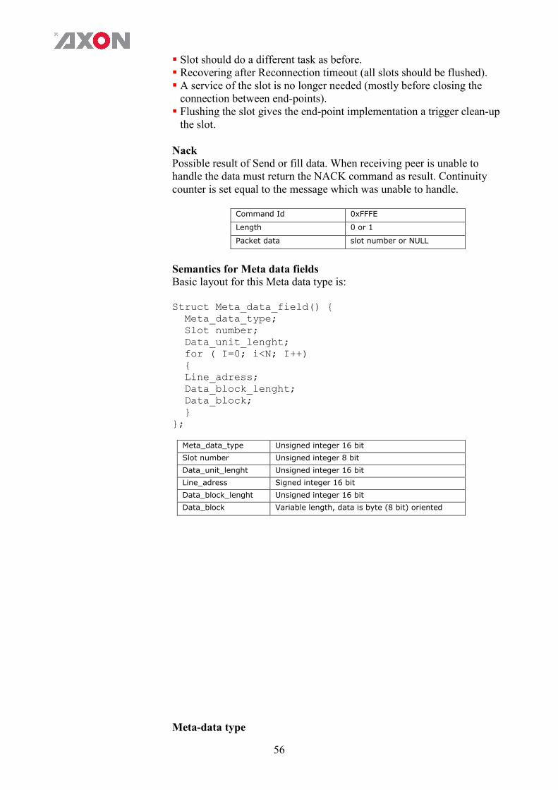
56
Slot should do a different task as before. Recovering after Reconnection timeout (all slots should be flushed). A service of the slot is no longer needed (mostly before closing the
connection between end-points). Flushing the slot gives the end-point implementation a trigger clean-up
the slot. Nack Possible result of Send or fill data. When receiving peer is unable to handle the data must return the NACK command as result. Continuity counter is set equal to the message which was unable to handle.
Command Id 0xFFFE
Length 0 or 1
Packet data slot number or NULL
Semantics for Meta data fields Basic layout for this Meta data type is: Struct Meta_data_field() { Meta_data_type; Slot number; Data_unit_lenght; for ( I=0; i<N; I++) { Line_adress; Data_block_lenght; Data_block; } };
Meta_data_type Unsigned integer 16 bit
Slot number Unsigned integer 8 bit
Data_unit_lenght Unsigned integer 16 bit
Line_adress Signed integer 16 bit
Data_block_lenght Unsigned integer 16 bit
Data_block Variable length, data is byte (8 bit) oriented
Meta-data type

57
Data type for Meta data used for insertion in VBI, ANC or OP47 data. (16 bit field) Note: implementations can be limited to a subset of these types. The product manual has a note which data types are actually supported.
WST-B Session layer
For transmission of raw Teletext data. The receiving end-point creates the Teletext service. Arrange resend behaviour etc.
0x0001
WST-B cooked For transferring transparent WST-b Teletext. The end point handles the WST-B transparent.
0x0002
OP47-SDP, like WST-B session.
For transmission of raw Teletext data. The receiving end-point creates the Teletext service. Arrange resend behaviour etc.
0x0003
OP47-SDP, like WST-B cooked
For transferring transparent WST-B Teletext. The end point handles the WST-B transparent. Packet as OP-47
0x0004
RESERVED Reserved for future 0x0005..0x03FF
Slot number This is the address of the internal buffer at which the data should be delivered. Delivered data to disabled or non existing slot should be discarded by the application. (8 bit field) Data unit length The data_unit_length is the total size of the Meta data in this object. Counted for all n lines included there data. (16 bit field) Line address Line address where the data must be located. Line number depends on the current video system. A code 0xFFFF is reserved for “don’t care”, use first available as defined in target slot. (16 bit field). Data block length Total length the data block for this line. (16 bit field) Data block The associated data block for VBI, ANC or VANC data. Meta Data block Descriptions WST-B session layer
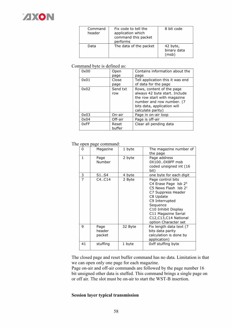
58
Command header
Fix code to tell the application which command this packet performs
8 bit code
Data The data of the packet 42 byte, binary data (msb)
Command byte is defined as:
0x00 Open page
Contains information about the page
0x01 Close page
Tell application this it was end of data for the page
0x02 Send txt row
Rows, content of the page always 42 byte start. Include the row start with magazine number and row number. (7 bits data, application will calculate parity)
0x03 On-air Page in on-air loop
0x04 Off-air Page is off-air
0xFF Reset buffer
Clear all pending data
The open page command:
0 Magazine 1 byte The magazine number of the page
1 Page Number
2 byte Page address 0X100..0X8FF msb coded unsigned int (16 bit)
3 S1..S4 4 byte one byte for each digit
7 C4..C14 2 Byte Page control bits C4 Erase Page lsb 20
C5 News Flash lsb 21
C7 Suppress Header C8 Update C9 Interrupted Sequence C10 Inhibit Display C11 Magazine Serial C12,C13,C14 National option Character set
9 Page header packet
32 Byte Fix length data text (7 bits data parity calculation is done by application)
41 stuffing 1 byte 0xff stuffing byte
The closed page and reset buffer command has no data. Limitation is that we can open only one page for each magazine. Page on-air and off-air commands are followed by the page number 16 bit unsigned other data is stuffed. This command brings a single page on or off air. The slot must be on-air to start the WST-B insertion. Session layer typical transmission

59
Clear buffer() Page_on-air(889)
Open page(888) …
Send txt row() Page_off-air(888)
.. Open page(888)
Send txt row() Send txt row()
Close page() Close page()
Page on-air(888) Page on-air(888)
Open page(889) Page off-air(888)
Send txt row()
Close page() Page_off-air(889)
WST-B cooked Raw WST-B line: length can be ether 42 bytes or 45 byte WST-B teletext serviced line. The data lines are ready for transmission thus parities are well calculated. Msb first oriented.
42 Byte Data contains the WST-B data lines: (each block of 1 byte)
45 Byte Data contains the WST-B data lines:

60
Appendix 1 GPI explained
Introduction This appendix describes the functionality of the GPI’s generally used within the Synapse based products.
General functionality
The physical contacts of a General Purpose Interface can be assigned by the user. In our cards the General Purpose Interface contacts (GPI contacts) will be named as General Purpose Input (GPI) or General Purpose Output (GPO). The GPI inputs and outputs are assignable to different preset banks. These preset banks (GPI pools) can be used to switch multiple settings at once. Some examples of these functions: Input selection Output mode Up conversion aspect ratio for channel A and B Down conversion aspect ratio for channel A and B Cross conversion aspect ratio for channel A and B Transparent aspect ratio (equal in-output) for channel A and B Insertion of VI, WSS, AFD (S2016) for channel A and B Audio shuffling, gain and phase
Contact assignment
The physical contacts can be assigned as input or output. In the menu of a card, these will be called Contact_N depending on the amount of contacts available. Contacts could be Inputs, outputs or bi-directional I/O. The Contact_N menu item will be used to assign this specific contact to input or output pools. The choices are Off, GPI_A, GPI_B, GPI_C, …, GPI_N, GPO_A, GPO_B, GPO_C, …, GPO_N depending on the amount of contacts and pools.
Pools
A GPI/GPO pool is a place where contacts are collected to form an output trigger.
GPI PoolActionCard
specific
1
n
2
3
Take

61
Take
The GPI contacts not only can be used as GPI contact but also can be assigned as Take contact. The menu item is called GPI_n-Take. Where n is the amount of GPI pools in the product. Every pool can only have one Take contact. There will be no restrictions in assigning the contact to a GPI pool and Take function at the same time. The values will be 1 to x. When assigning a take pin to a pool set to Prio_Latched mode, the pool will behave the same as when set to Prio mode with a take pin assigned. This is because the take pin overrules the latched functionality of the Prio_Latched mode.
Pool Mode: GPI
Every GPI pool can be set up to process the input contacts in three ways. This setting is called GPI_n-Mode and can be set into priority (Prio), priority latched (Prio_Latched) and Binary mode. N is defined as a character in the range from A-Z depending on the number of pools. The default output value of a pool is always 0. This translates to preset 1 in Axon products. In priority mode, the contact which has the highest priority defines the pool value. Priority is defined as ranging from the least significant bit (low priority) to the most significant bit (high priority). This is essentially a one-hot coding of preset values. If a pool has three contacts connected and all inputs are high, the output value of the pool will be 3. Another example is when three contacts are connected to a pool with the first and third contact are low and the second contact is high the output value is 1.
Input 1
Input 2
Input 3 Pool value
Preset nr
0 0 0 1 1 1 0 0 1 1 X 1 0 2 2 X X 1 3 3
Table 1 Pool value in prio and prio_latched mode
In binary mode, the contacts are interpreted as a binary value of concatenated contacts available in a pool. E.g. assigning two contacts to a GPI pool translates to the following output values.
Input 1
Input 2 Pool value
Preset nr
0 0 1 1 0 1 2 2 1 0 3 3 1 1 4 4
Table 2 Pool value in binary mode
Pool Mode: GPO Every GPO pool can be set up to process the input values in two ways.

62
This setting is called GPO_n-Mode and can be set into Priority (Prio) or Binary mode. N is defined as a character in the range from A-Z depending on the number of pools. The default output value of a pool is always 0.
GPO PoolStatus Card
specific
1
n
2
3
1
x
2
3
Every GPO pool can be set up to process the input values in two ways. This setting is called GPO_n-Mode and can be set into Priority (Prio) or Binary mode. N is defined as a character in the range from A-Z depending on the number of pools. The default output value of a pool is always 0. In priority mode, the value is translated to one-hot encoding on the output contacts. See table below.
Preset nr Output 1 Output 2 Output 3 Pool value
1 1 0 0 1 2 0 1 0 2 3 0 0 1 3
Table 3 Pool value in priority mode
In binary mode the input value is exposed on the output contacts as binary value.
Preset nr
Output 1
Output 2
Pool value
1 0 0 1 2 0 1 2 3 1 0 3 4 1 1 4
Table 4 Pool value in binary mode
GPO_n-Source is the setting with which a function is assigned to a GPO pool. E.g. when the output format needs to be reflected on the output contacts, this setting may be set to something like Output_Format. The contents of the enumeration are product specific.
Statuses: Contact direction
This status Contact-Dir shows the direction of the physical contacts. The value will be presented as a concatenated string containing one character per pin: I for Input, O for output and _ for unassigned contacts.
Statuses: Contact Contact-Status shows the current logical value of the physical
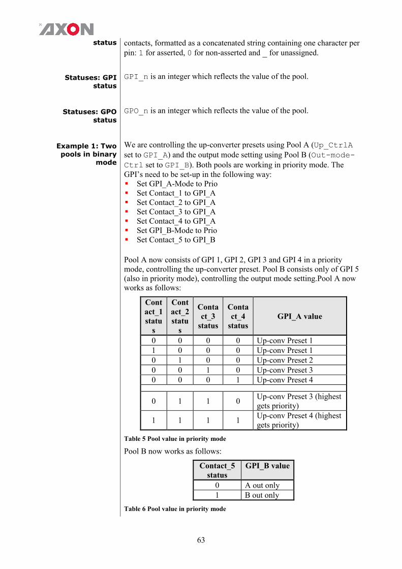
63
status contacts, formatted as a concatenated string containing one character per pin: 1 for asserted, 0 for non-asserted and _ for unassigned.
Statuses: GPI status
GPI_n is an integer which reflects the value of the pool.
Statuses: GPO status
GPO_n is an integer which reflects the value of the pool.
Example 1: Two pools in binary
mode
We are controlling the up-converter presets using Pool A (Up_CtrlA set to GPI_A) and the output mode setting using Pool B (Out-mode-Ctrl set to GPI_B). Both pools are working in priority mode. The GPI’s need to be set-up in the following way: Set GPI_A-Mode to Prio Set Contact_1 to GPI_A Set Contact_2 to GPI_A Set Contact_3 to GPI_A Set Contact_4 to GPI_A Set GPI_B-Mode to Prio Set Contact_5 to GPI_B
Pool A now consists of GPI 1, GPI 2, GPI 3 and GPI 4 in a priority mode, controlling the up-converter preset. Pool B consists only of GPI 5 (also in priority mode), controlling the output mode setting.Pool A now works as follows:
Contact_1 statu
s
Contact_2 statu
s
Contact_3
status
Contact_4
status GPI_A value
0 0 0 0 Up-conv Preset 1 1 0 0 0 Up-conv Preset 1 0 1 0 0 Up-conv Preset 2 0 0 1 0 Up-conv Preset 3 0 0 0 1 Up-conv Preset 4
0 1 1 0 Up-conv Preset 3 (highest gets priority)
1 1 1 1 Up-conv Preset 4 (highest gets priority)
Table 5 Pool value in priority mode
Pool B now works as follows:
Contact_5 status
GPI_B value
0 A out only 1 B out only
Table 6 Pool value in priority mode
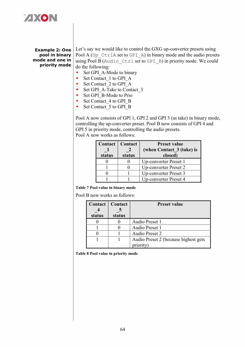
64
Example 2: One pool in binary
mode and one in priority mode
Let’s say we would like to control the GXG up-converter presets using Pool A (Up_CtrlA set to GPI_A) in binary mode and the audio presets using Pool B (Audio_Ctrl set to GPI_B) in priority mode. We could do the following: Set GPI_A-Mode to binary Set Contact_1 to GPI_A Set Contact_2 to GPI_A Set GPI_A-Take to Contact_3 Set GPI_B-Mode to Prio Set Contact_4 to GPI_B Set Contact_5 to GPI_B Pool A now consists of GPI 1, GPI 2 and GPI 3 (as take) in binary mode, controlling the up-converter preset. Pool B now consists of GPI 4 and GPI 5 in priority mode, controlling the audio presets. Pool A now works as follows:
Contact_1
status
Contact_2
status
Preset value (when Contact_3 (take) is
closed)
0 0 Up-converter Preset 1 1 0 Up-converter Preset 2 0 1 Up-converter Preset 3 1 1 Up-converter Preset 4
Table 7 Pool value in binary mode
Pool B now works as follows:
Contact_4
status
Contact_5
status
Preset value
0 0 Audio Preset 1 1 0 Audio Preset 1 0 1 Audio Preset 2 1 1 Audio Preset 2 (because highest gets
priority)
Table 8 Pool value in priority mode
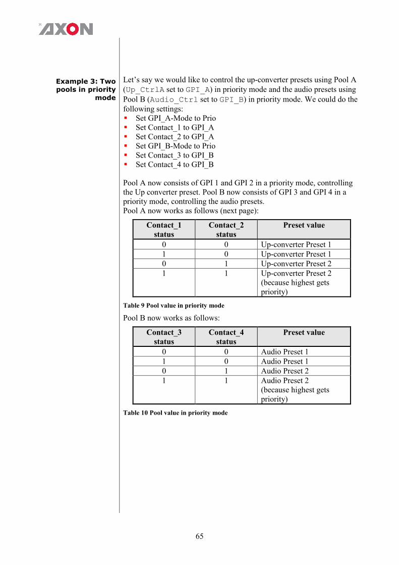
65
Example 3: Two pools in priority
mode
Let’s say we would like to control the up-converter presets using Pool A (Up_CtrlA set to GPI_A) in priority mode and the audio presets using Pool B (Audio_Ctrl set to GPI_B) in priority mode. We could do the following settings: Set GPI_A-Mode to Prio Set Contact_1 to GPI_A Set Contact_2 to GPI_A Set GPI_B-Mode to Prio Set Contact_3 to GPI_B Set Contact_4 to GPI_B Pool A now consists of GPI 1 and GPI 2 in a priority mode, controlling the Up converter preset. Pool B now consists of GPI 3 and GPI 4 in a priority mode, controlling the audio presets. Pool A now works as follows (next page):
Contact_1 status
Contact_2 status
Preset value
0 0 Up-converter Preset 1 1 0 Up-converter Preset 1 0 1 Up-converter Preset 2 1 1 Up-converter Preset 2
(because highest gets priority)
Table 9 Pool value in priority mode
Pool B now works as follows:
Contact_3 status
Contact_4 status
Preset value
0 0 Audio Preset 1 1 0 Audio Preset 1 0 1 Audio Preset 2 1 1 Audio Preset 2
(because highest gets priority)
Table 10 Pool value in priority mode

66
This product contains open-source software This product contains open-source software licensed under the GNU Public License (GPL). A copy of the GNU Public License is included below. Under this license you are eligible to receive a copy of the source code of this software including any changes. Axon Digital Design shall provide the source code on request either through physical distribution or electronic communication. For physical distribution you may be charged a fee that covers distribution costs. This offer is valid up to three years after date of purchase. Please direct your request to the support department of Axon Digital Design. Axon Digital Design supports open-source software by participating in the development of open-source projects or submitting improvements to these projects. For more information see http://opensource.axon.tv/
GNU Public License version 2 TERMS AND CONDITIONS FOR COPYING, DISTRIBUTION AND MODIFICATION 0. This License applies to any program or other work which contains a notice placed by the copyright holder saying it may be distributed under the terms of this General Public License. The “Program”, below, refers to any such program or work, and a “work based on the Program” means either the Program or any derivative work under copyright law: that is to say, a work containing the Program or a portion of it, either verbatim or with modifi cations and/or translated into another language. (Hereinafter, translation is included without limitation in the term “modifi cation”.) Each licensee is addressed as “you”. Activities other than copying, distribution and modifi cation are not covered by this License; they are outside its scope. The act of running the Program is not restricted, and the output from the Program is covered only if its contents constitute a work based on the Program (independent of having been made by running the Program). Whether that is true depends on what the Program does. 1. You may copy and distribute verbatim copies of the Program’s source code as you receive it, in any medium, provided that you conspicuously and appropriately publish on each copy an appropriate copyright notice and disclaimer of warranty; keep intact all the notices that refer to this License and to the absence of any warranty; and give any other recipients of the Program a copy of this License along with the Program. You may charge a fee for the physical act of transferring a copy, and you may at your option offer warranty protection in exchange for a fee. 2. You may modify your copy or copies of the Program or any portion of it, thus forming a work based on the Program, and copy and distribute such modifications or work under the terms of Section 1 above, provided that you also meet all of these conditions:
a) You must cause the modified files to carry prominent notices stating that you changed the fi les and the date of any change. b) You must cause any work that you distribute or publish, that in whole or in part contains or is derived from the Program or any
part thereof, to be licensed as a whole at no charge to all third parties under the terms of this License. c) If the modified program normally reads commands interactively when run, you must cause it, when started running for such
interactive use in the most ordinary way, to print or display an announcement including an appropriate copyright notice and a notice that there is no warranty (or else, saying that you provide a warranty) and that users may redistribute the program under these conditions, and telling the user how to view a copy of this License. (Exception: if the Program itself is interactive but does not normally print such an announcement, your work based on the Program is not required to print an announcement.)
These requirements apply to the modified work as a whole. If identifiable sections of that work are not derived from the Program, and can be reasonably considered independent and separate works in themselves, then this License, and its terms, do not apply to those sections when you distribute them as separate works. But when you distribute the same sections as part of a whole which is a work based on the Program, the distribution of the whole must be on the terms of this License, whose permissions for other licensees extend to the entire whole, and thus to each and every part regardless of who wrote it. Thus, it is not the intent of this section to claim rights or contest your rights to work written entirely by you; rather, the intent is to exercise the right to control the distribution of derivative or collective works based on the Program. In addition, mere aggregation of another work not based on the Program with the Program (or with a work based on the Program) on a volume of a storage or distribution medium does not bring the other work under the scope of this License. 3. You may copy and distribute the Program (or a work based on it, under Section 2) in object code or executable form under the terms of Sections 1 and 2 above provided that you also do one of the following:
a) Accompany it with the complete corresponding machine-readable source code, which must be distributed under the terms of Sections 1 and 2 above on a medium customarily used for software interchange; or,
b) Accompany it with a written offer, valid for at least three years, to give any third party, for a charge no more than your cost of physically performing source distribution, a complete machine-readable copy of the corresponding source code, to be distributed under the terms of Sections 1 and 2 above on a medium customarily used for software interchange; or,

67
c) Accompany it with the information you received as to the offer to distribute corresponding source code. (This alternative is allowed only for noncommercial distribution and only if you received the program in objects code or executable form with such an offer, in accord with Subsection b above.)
The source code for a work means the preferred form of the work for making modifi cations to it. For an executable work, complete source code means all the source code for all modules it contains, plus any associated interface defi nition fi les, plus the scripts used to control compilation and installation of the executable. However, as a special exception, the source code distributed need not include anything that is normally distributed (in either source or binary form) with the major components (compiler, kernel, and so on) of the operating system on which the executable runs, unless that component itself accompanies the executable. If distribution of executable or object code is made by offering access to copy from a designated place, then offering equivalent access to copy the source code from the same place counts as distribution of the source code, even though third parties are not compelled to copy the source along with the object code. 4. You may not copy, modify, sublicense, or distribute the Program except as expressly provided under this License. Any attempt otherwise to copy, modify, sublicense or distribute the Program is void, and will automatically terminate your rights under this License. However, parties who have received copies, or rights, from you under this License will not have their licenses terminated so long as such parties remain in full compliance. 5. You are not required to accept this License, since you have not signed it. However, nothing else grants you permission to modify or distribute the Program or its derivative works. These actions are prohibited by law if you do not accept this License. Therefore, by modifying or distributing the Program (or any work based on the Program), you indicate your acceptance of this License to do so, and all its terms and conditions for copying, distributing or modifying the Program or works based on it. 6. Each time you redistribute the Program (or any work based on the Program), the recipient automatically receives a license from the original licensor to copy, distribute or modify the Program subject to these terms and conditions. You may not impose any further restrictions on the recipients’ exercise of the rights granted herein. You are not responsible for enforcing compliance by third parties to this License. 7. If, as a consequence of a court judgment or allegation of patent infringement or for any other reason (not limited to patent issues), conditions are imposed on you (whether by court order, agreement or otherwise) that contradict the conditions of this License, they do not excuse you from the conditions of this License. If you cannot distribute so as to satisfy simultaneously your obligations under this License and any other pertinent obligations, then as a consequence you may not distribute the Program at all. For example, if a patent license would not permit royalty-free redistribution of the Program by all those who receive copies directly or indirectly through you, then the only way you could satisfy both it and this License would be to refrain entirely from distribution of the Program. If any portion of this section is held invalid or unenforceable under any particular circumstance, the balance of the section is intended to apply and the section as a whole is intended to apply in other circumstances. It is not the purpose of this section to induce you to infringe any patents or other property right claims or to contest validity of any such claims; this section has the sole purpose of protecting the integrity of the free software distribution system, which is implemented by public license practices. Many people have made generous contributions to the wide range of software distributed through that system in reliance on consistent application of that system; it is up to the author/donor to decide if he or she is willing to distribute software through any other system and a licensee cannot impose that choice. This section is intended to make thoroughly clear what is believed to be a consequence of the rest of this License. 8. If the distribution and/or use of the Program is restricted in certain countries either by patents or by copyrighted interfaces, the original copyright holder who places the Program under this License may add an explicit geographical distribution limitation excluding those countries, so that distribution is permitted only in or among countries not thus excluded. In such case, this License incorporates the limitation as if written in the body of this License. 9. The Free Software Foundation may publish revised and/or new versions of the General Public License from time to time. Such new versions will be similar in spirit to the present version, but may differ in detail to address new problems or concerns. Each version is given a distinguishing version number. If the Program specifies a version number of this License which applies to it and “any later version”, you have the option of following the terms and conditions either of that version or of any later version published by the Free Software Foundation. If the Program does not specify a version number of this License, you may choose any version ever published by the Free Software Foundation. 10. If you wish to incorporate parts of the Program into other free programs whose distribution conditions are different, write to the author to ask for permission. For software which is copyrighted by the Free Software Foundation, write to the Free Software Foundation; we sometimes make exceptions for this. Our decision will be guided by the two goals of preserving the free status of all derivatives of our free software and of promoting the sharing and reuse of software generally.

68
NO WARRANTY 11. BECAUSE THE PROGRAM IS LICENSED FREE OF CHARGE, THERE IS NO WARRANTY FOR THE PROGRAM, TO THE EXTENT PERMITTED BY APPLICABLE LAW. EXCEPT WHEN OTHERWISE STATED IN WRITING THE COPYRIGHT HOLDERS AND/OR OTHER PARTIES PROVIDE THE PROGRAM “AS IS” WITHOUT WARRANTY OF ANY KIND, EITHER EXPRESSED OR IMPLIED, INCLUDING, BUT NOT LIMITED TO, THE IMPLIED WARRANTIES OF MERCHANTABILITY AND FITNESS FOR A PARTICULAR PURPOSE. THE ENTIRE RISK AS TO THE QUALITY AND PERFORMANCE OF THE PROGRAM IS WITH YOU. SHOULD THE PROGRAM PROVE DEFECTIVE, YOU ASSUME THE COST OF ALL NECESSARY SERVICING, REPAIR OR CORRECTION. 12. IN NO EVENT UNLESS REQUIRED BY APPLICABLE LAW OR AGREED TO IN WRITING WILL ANY COPYRIGHT HOLDER, OR ANY OTHER PARTY WHO MAY MODIFY AND/OR REDISTRIBUTE THE PROGRAM AS PERMITTED ABOVE, BE LIABLE TO YOU FOR DAMAGES, INCLUDING ANY GENERAL, SPECIAL, INCIDENTAL OR CONSEQUENTIAL DAMAGES ARISING OUT OF THE USE OR INABILITY TO USE THE PROGRAM (INCLUDING BUT NOT LIMITED TO LOSS OF DATA OR DATA BEING RENDERED INACCURATE OR LOSSES SUSTAINED BY YOU OR THIRD PARTIES OR A FAILURE OF THE PROGRAM TO OPERATE WITH ANY OTHER PROGRAMS), EVEN IF SUCH HOLDER OR OTHER PARTY HAS BEEN ADVISED OF THE POSSIBILITY OF SUCH DAMAGES.