
GMOS Standard Operational Procedure SOP TGM_GEM.pdf · GMOS Standard Operational Procedure 1. ......
32
GMOS Stand Methods for the det dard Operational Proced termination of TGM and GEM dure
Transcript of GMOS Standard Operational Procedure SOP TGM_GEM.pdf · GMOS Standard Operational Procedure 1. ......
GMOS Standard Operational Procedure
Methods for the determination of TGM and GEM
GMOS Standard Operational Procedure
Methods for the determination of TGM and GEM
GMOS Standard Operational Procedure
2
Foreword This Standard Operational Procedure (SOP) is for the continuous measurement of TGM and/or GEM in ambient air using either the Tekran 2537 or the Lumex RA 915 AM. This SOP is based upon the European standard (NEN-EN 15852 (en)) for TGM and GEM measurements [1] and the Canadian CAMNet/CAPMoN SOP for TGM measurements [2]. Technical information is provided from the instrument manuals for the Tekran Model 2537 Mercury Vapour Analyser [3] and the corresponding manual for the Lumex RA 915 AM Automatic Mercury Monitor [4]. This SOP was generated concurrently with the GMOS SOP for speciated mercury measurements in ambient air so as to ensure consistency in the atmospheric mercury measurements being performed within the GMOS project. Furthermore, this GMOS SOP was revised during a workshop in Brussels, Belgium on 7-8 April, 2011 in which the participating GMOS partners provided input and suggestions on the procedures described in this document. The present version of this GMOS SOP can be used as a reference guide when starting up TGM and GEM measurements. It also contains quality control protocols to be used in the field when performing TGM and GEM measurements. More detailed technical information can also be found in the Tekran 2537A/Band Lumex RA 915 AM manuals. It should be noted that in this SOP, requirements and recommendations are both provided where appropriate. Requirements (typically noted by the words “shall” or “must”) are guidelines that must be followed at all sites. Recommendations are suggestions that allow for some flexibility in the procedures based upon the specific characteristics of each site. Careful attention should be paid to these guidelines for GMOS monitoring sites.

Table of Contents
................................................................
GMOS Standard Operational Procedure
1. Scope ................................................................
2. Abbreviations and Definitions
3. Gases and chemicals ................................
4. Principle of TGM and GEM measurements
5. Siting requirements for TGM /GEM measurement
6. General requirements regarding TGM/GEM measurements
7. Operation and routine maintenance of the Tekran and Lumex systems
7.1 Recommended instrument settings for the Tekran model 2537A/B instrument
7.2 Maintenance procedures for the Tekran model 2537A/B instrument
7.3 Instrument settings for the Lumex RA 915 AM instrument
7.4 Routine checks and maintenance
7.5 Calibration ................................
8. Data download, storage, and management
9. Quality control and quality assurance
10. References ................................
Annex A
Annex B
Annex C
Annex D
Annex E
Annex F
3
.........................................................................................
GMOS Standard Operational Procedure ................................................................................................
................................................................................................
Abbreviations and Definitions ................................................................................................
................................................................................................
Principle of TGM and GEM measurements................................................................
Siting requirements for TGM /GEM measurement ................................................................
requirements regarding TGM/GEM measurements ................................
Operation and routine maintenance of the Tekran and Lumex systems ................................
Recommended instrument settings for the Tekran model 2537A/B instrument
Maintenance procedures for the Tekran model 2537A/B instrument ................................
Instrument settings for the Lumex RA 915 AM instrument ................................
Routine checks and maintenance of the Lumex RA 915 AM instrument
..................................................................... Errore. Il segnalibro non è definito.
Data download, storage, and management ................................................................
Quality control and quality assurance ................................................................
................................................................................................................................
................................. 1
............................................... 4
........................................ 4
....................................................... 5
.................................................... 6
........................................ 7
.......................................................... 9
....................................... 10
Recommended instrument settings for the Tekran model 2537A/B instrument .................. 10
................................... 11
................................................. 14
of the Lumex RA 915 AM instrument ............................ 15
Errore. Il segnalibro non è definito.
.................................................... 16
........................................................... 18
................................. 19
4
1. Scope This Standard Operational Procedure describes methods for determining total gaseous mercury (TGM) and gaseous elemental mercury (GEM) in ambient air using the Tekran 2537 or the Lumex RA 915 AM. The Tekran system uses CVAFS to quantify ambient mercury concentrations, while the Lumex system uses Zeeman CVAAS. The proper operation and maintenance of the Tekran and Lumex systems are described below. This operating procedure is designed to support consistent and systematic sampling among the contributing GMOS sites. Results are reported as the average mass of TGM or GEM per volume of air at 273.15 K and 101.325 kPa, measured over a specified time period. The time should be reported as GMT time and concentrations should be reported as ng m-3.
2. Abbreviations and Definitions Mercury Species: Hg Mercury
TGM Total Gaseous Mercury: the summary of gas phase species of mercury, including ground state and reactive forms
GEM Gaseous Elemental Mercury (Hg0): gas phase mercury in its ground electronic state
Analytical Terms: CVAAS Cold Vapour Atomic Absorption Spectrometry
CVAFS Cold Vapour Atomic Fluorescence Spectrometry
Zeeman CVAAS Zeeman Cold Vapour Atomic Absorption Spectrometry
MFC Mass flow controller
MFM Mass flow meter
Zero air Pre-filtered mercury free air used for calibration
UHP Ultra High Purity (e.g. for Argon gas used by the Tekran; grade 4.8 (99.998%) or higher)
MDL Method Detection Limit: the minimum concentration of a substance that can be measured and reported with 99% confidence that the concentration is greater than zero
QA Quality Assurance
QC Quality Control
Units: ng Nanogram; 10-9 g
ng m-3 nanograms per cubic meter
°C degrees Celsius
cm centimeters
5
L liters
lpm liters per minute
psi pounds per square inch
kPa kilopascals
V volts
3. Gases and chemicals 3.1 Grade 4.8 (99.998%) or higher ultra high purity (UHP) Argon for use as a carrier gas
for the CVAFS within the Tekran 2537.
3.2 Nitrogen, of purity greater than 99.999 %, suitable for use as a carrier gas for CVAAS.
3.3 Air, of class 3.3.3 purity or better according to ISO 8573-1:2010.
3.4 Elemental mercury, of purity 99.9999 %, for preparation of gaseous mercury vapour standard. WARNING — Mercury is toxic by skin absorption and inhalation of vapour. Use suitable personal protective equipment (including gloves, face shield or safety glasses, etc.) and minimize exposure by using a fume hood. 3.5 Reagent grade water: ultrapure deionised water with resistivity greater or equal to 18
MΩ cm that originated from a pre-purified (distilled, reverse osmosis, etc.) source.
3.6 Hydrochloric acid (HCl), concentrated, density ~ 1.18 g/ml, mass fraction 36 % to 38 %.The concentration of mercury shall be less than 0.002 mg/l.
3.7 Hydrochloric acid (3.6), diluted 1:49 with deionised water (3.5) for cleaning of filter housings, and other and sampling components. WARNING — concentrated hydrochloric acid is corrosive and is also an irritant. Avoid contact with the skin and eyes, or inhalation of the vapour. Use suitable personal protective equipment (including gloves, face shield or safety glasses, etc.) when working with hydrochloric acid. Handle open vessels containing concentrated hydrochloric acid in a fume hood. The vapour pressure of hydrochloric acid is high. Therefore beware of pressure build-upin capped vessels when preparing dilute hydrochloric solutions. 3.8 Laboratory grade methanol: to use for cleaning and drying sampling components.
3.9 Soda lime: soda lime traps are often placed upstream of the detector sample filter to remove free halogens that can shorten the life of the gold trap cartridges. Soda lime should be non-indicating, 4-8 mesh, and free of mercury. Laboratories should contact one of the GMOS work package leaders for information about where and how to purchase acceptable soda lime for the Tekran system.
3.10 Internal permeation source: the 2537 analyzers are equipped with internal permeation sources capable of calibrating the system automatically at a preset time or manually when initiated by the operator.

4. Principle of TGM and GEM measurements Total gaseous mercury (TGM) is the sum of gaseous oxidised mercury (GOM)gaseous mercury species. Hgbackground atmosphere and constitutes often more than 98Automatic TGM instruments use the amalgamation technique to trap gaseous mercury in the air. Exactly determined air volumes are pulled through a cartridge containing an adsorbent (a gold surface), onto which all gaseous mercury quantitatively is adsorbed. The mercury is then thermally desorbed as GEM (Hgmass of Hg0 as a function of the detector response is obtained by calibration using known amounts of Hg0 vapour. The accuracy of the measurement depends on the accuracy of the calibration and the air volume measurements. Normally mass flow controllers or mass flmeters are used to determine the air volume. The TGM concentration is presented as ng Hg0 per m3, using volumes at standard pressure and temperature. The CVAFS instruments are more sensitive in comparison to CVAAS, but requiand detection step, whereas CVAAS instruments use mercury free air or nitrogen. GEM can automatically be measured by pumping ambient air through a longand determining the absorbance of gaseous Hgsignal is calibrated against known concentrations of Hgconcentration of Hg0 in the air inside the optical cell is obtained. This technique does not require precise volume measurements. However, the pressure and tinstrument must be measured in order to recalculate the Hgpressure and temperature. The accuracy of the measurement largely depends on the calibration but also on the internal pressure and temperature measureme Ambient concentrations of GEM may also be directly measured using cavity ringspectroscopy (CRDS) which also is a CVAAS technique that uses a longSimilar requirements as for Zeeman CVAAS apply regarding the accuracy. Both CVAFS and CVAAS instruments detect mercury as GEM by UV radiation at 253.7 nm. The fluorescence signal (F) obtained with CVAFS is (after base line correction) directly proportional to the excitation intensity (I
Measurement with CVAAS, requires determination of the total UVHg0 (I0) and in the presence of
6
Principle of TGM and GEM measurements
Total gaseous mercury (TGM) is the sum of gaseous elemental mercury ((GOM), which may constitute from both inorganic and organic
gaseous mercury species. Hg0 is generally the most dominating mercury species in the constitutes often more than 98% of the total gaseous mercury.
Automatic TGM instruments use the amalgamation technique to trap gaseous mercury in the air volumes are pulled through a cartridge containing an adsorbent (a
gold surface), onto which all gaseous mercury quantitatively is adsorbed. The mercury is then thermally desorbed as GEM (Hg0) and detected by CVAFS or alternatively by CVAAS. The
function of the detector response is obtained by calibration using known vapour. The accuracy of the measurement depends on the accuracy of the
calibration and the air volume measurements. Normally mass flow controllers or mass flmeters are used to determine the air volume. The TGM concentration is presented as ng
, using volumes at standard pressure and temperature. The CVAFS instruments are more sensitive in comparison to CVAAS, but require pure Ar or He gas durinand detection step, whereas CVAAS instruments use mercury free air or nitrogen.
GEM can automatically be measured by pumping ambient air through a longand determining the absorbance of gaseous Hg0 using Zeeman CVAAS. Thsignal is calibrated against known concentrations of Hg0 vapour. With this method the
in the air inside the optical cell is obtained. This technique does not require precise volume measurements. However, the pressure and tinstrument must be measured in order to recalculate the Hg0 concentration to standard pressure and temperature. The accuracy of the measurement largely depends on the calibration but also on the internal pressure and temperature measurements.
Ambient concentrations of GEM may also be directly measured using cavity ringspectroscopy (CRDS) which also is a CVAAS technique that uses a longSimilar requirements as for Zeeman CVAAS apply regarding the accuracy.
AFS and CVAAS instruments detect mercury as GEM by UV radiation at 253.7 nm. The fluorescence signal (F) obtained with CVAFS is (after base line correction) directly proportional to the excitation intensity (Ie) times the concentration of GEM,
Equation 4.1
Measurement with CVAAS, requires determination of the total UV-intensity in absence of ) and in the presence of Hg0 (I),
Equation 4.2
gaseous elemental mercury (Hg0; GEM) and , which may constitute from both inorganic and organic
is generally the most dominating mercury species in the % of the total gaseous mercury.
Automatic TGM instruments use the amalgamation technique to trap gaseous mercury in the air volumes are pulled through a cartridge containing an adsorbent (a
gold surface), onto which all gaseous mercury quantitatively is adsorbed. The mercury is then ) and detected by CVAFS or alternatively by CVAAS. The
function of the detector response is obtained by calibration using known vapour. The accuracy of the measurement depends on the accuracy of the
calibration and the air volume measurements. Normally mass flow controllers or mass flow meters are used to determine the air volume. The TGM concentration is presented as ng of
, using volumes at standard pressure and temperature. The CVAFS instruments are re pure Ar or He gas during the desorption
and detection step, whereas CVAAS instruments use mercury free air or nitrogen.
GEM can automatically be measured by pumping ambient air through a long-path optical cell using Zeeman CVAAS. The absorption
vapour. With this method the in the air inside the optical cell is obtained. This technique does not
emperature in the concentration to standard
pressure and temperature. The accuracy of the measurement largely depends on the nts.
Ambient concentrations of GEM may also be directly measured using cavity ring-down spectroscopy (CRDS) which also is a CVAAS technique that uses a long-path optical cell. Similar requirements as for Zeeman CVAAS apply regarding the accuracy.
AFS and CVAAS instruments detect mercury as GEM by UV radiation at 253.7 nm. The fluorescence signal (F) obtained with CVAFS is (after base line correction) directly
) times the concentration of GEM,
intensity in absence of

7
5. Siting requirements for TGM /GEM measurement Two types of sites shall exist within the GMOS project: Master Sites will measure continuous speciated ambient mercury (GEM, GOM, and PBM2.5) and total mercury in precipitation. Secondary Sites will measure total gaseous mercury (TGM) or gaseous elemental mercury (GEM) in the ambient atmosphere and total mercury in precipitation. The following siting requirements shall be followed when establishing new GMOS sites:
1. It is recommended that the GMOS monitoring sites be located in background areas which are not directly impacted by anthropogenic emissions of mercury or other airborne pollutants. The sites shall be representative of a large area, i.e. the concentration(s) of mercury obtained at the site shall be representative for the region where the measurements are performed. Measurement sites close to natural mercury emission sources, such as active volcanoes, are not recommended unless the measured ambient mercury is actually representative for a large area.
2. GMOS sites shall be chosen based on existing sites that can provide available ancillary measurements. Examples include EMEP and GAW sites. In this way, the site will have the necessary existing infrastructure for atmospheric mercury monitoring, including available power, shelter, and site personnel.
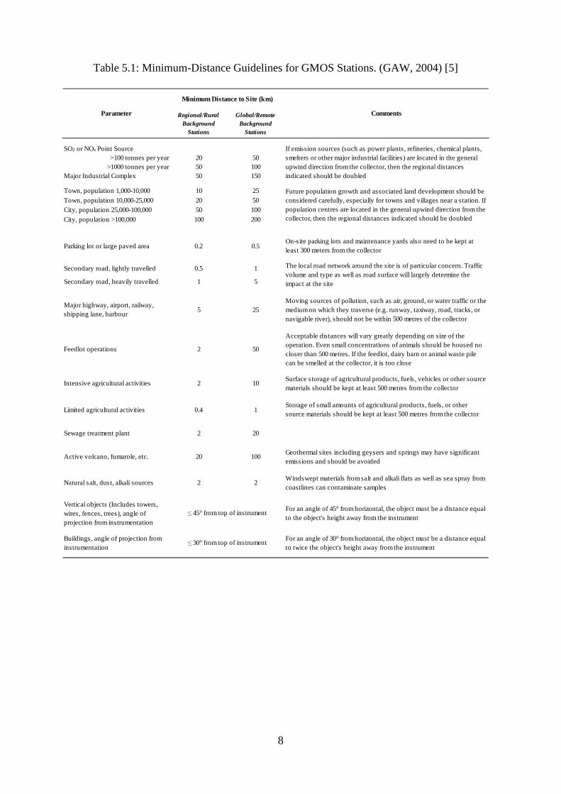
3. It is recommended that GMOS sites be selected based upon the criteria set forth by GAW with respect to distances from major natural and anthropogenic sources. Stations within the GAW framework are categorized as either global or regional with respect to the remote nature of the sites and the relative impact of sources and pollutants. Within GMOS, it is strongly recommended that sites satisfy the minimum-distance guidelines of global background stations; however, regional background stations may be permitted depending on the specific site characteristics (Table 5.1).
4. The monitoring sites shall be as exposed as possible without influence from surrounding topography or other obstacles within a 2 km radius around the site. Naturally vegetated areas with level ground are recommended [5]. Vegetation surrounding the site should be maintained at < 0.5 m and not higher than half the height of the measurement device (e.g. precipitation collector) [5].
5. The sites must have sufficient power available to support the operation of desired sampling equipment. Responsible personnel must review the instrument specifications to determine whether the site has the necessary capabilities.
6. All activities near the site shall be recorded on a regular basis. This includes active natural and anthropogenic sources, motor vehicle traffic, distance to population centers, activity of major wildlife, and frequency of people visiting the monitoring site. This is critical for understanding variability in the measurement data.
8
Regional/Rural Background
Stations
Global/Remote Background
Stations
SO2 or NOx Point Source >100 tonnes per year 20 50
>1000 tonnes per year 50 100Major Industrial Complex 50 150
Town, population 1,000-10,000 10 25Town, population 10,000-25,000 20 50City, population 25,000-100,000 50 100City, population >100,000 100 200
Parking lot or large paved area 0.2 0.5On-site parking lots and maintenance yards also need to be kept at least 300 meters from the collector
Secondary road, lightly travelled 0.5 1
Secondary road, heavily travelled 1 5
Major highway, airport, railway, shipping lane, harbour
5 25Moving sources of pollution, such as air, ground, or water traffic or the medium on which they traverse (e.g. runway, taxiway, road, tracks, or navigable river), should not be within 500 metres of the collector
Feedlot operations 2 50
Acceptable distances will vary greatly depending on size of the operation. Even small concentrations of animals should be housed no closer than 500 metres. If the feedlot, dairy barn or animal waste pile can be smelled at the collector, it is too close
Intensive agricultural activities 2 10Surface storage of agricultural products, fuels, vehicles or other source materials should be kept at least 500 metres from the collector
Limited agricultural activities 0.4 1Storage of small amounts of agricultural products, fuels, or other source materials should be kept at least 500 metres from the collector
Sewage treatment plant 2 20
Active volcano, fumarole, etc. 20 100Geothermal sites including geysers and springs may have significant emissions and should be avoided
Natural salt, dust, alkali sources 2 2Windswept materials from salt and alkali flats as well as sea spray from coastlines can contaminate samples
Vertical objects (Includes towers, wires, fences, trees), angle of projection from instrumentation
For an angle of 45° from horizontal, the object must be a distance equal to the object's height away from the instrument
Buildings, angle of projection from instrumentation
For an angle of 30° from horizontal, the object must be a distance equal to twice the object's height away from the instrument
Parameter Comments
Minimum Distance to Site (km)
≤ 30° from top of instrument
≤ 45° from top of instrument
If emission sources (such as power plants, refineries, chemical plants, smelters or other major industrial facilities) are located in the general upwind direction from the collector, then the regional distances indicated should be doubled
Future population growth and associated land development should be considered carefully, especially for towns and villages near a station. If population centres are located in the general upwind direction from the collector, then the regional distances indicated should be doubled
The local road network around the site is of particular concern. Traffic volume and type as well as road surface will largely determine the impact at the site
Table 5.1: Minimum-Distance Guidelines for GMOS Stations. (GAW, 2004) [5]
6. General requirements regarding TGM/GEM measurements Monitoring of TGM and GEM using automatic instruments requires a measurement cabin or house to contain the mercury instrument and additional equipment. The mercury analyzer should be housed in a sheltered, mercurystructure with a bench space of Power requirements for the Tekran 2537A/B are 100/120 V, 50VA average [2]. Power requirements for the Lumex RA 915 are220VA max [4]. The air to be sampled is pulled via a sample inlet and a sample line to the instrument. The inlet should be installed in a free position at least 2 m above the ground so that the air flow around the sampling inlet is unrestricted. Obstructions to the and other obstacles shall be avoided. The sampling system should be positioned such that the inlet is ≤ 45° from vertical objects and trees, and ≤
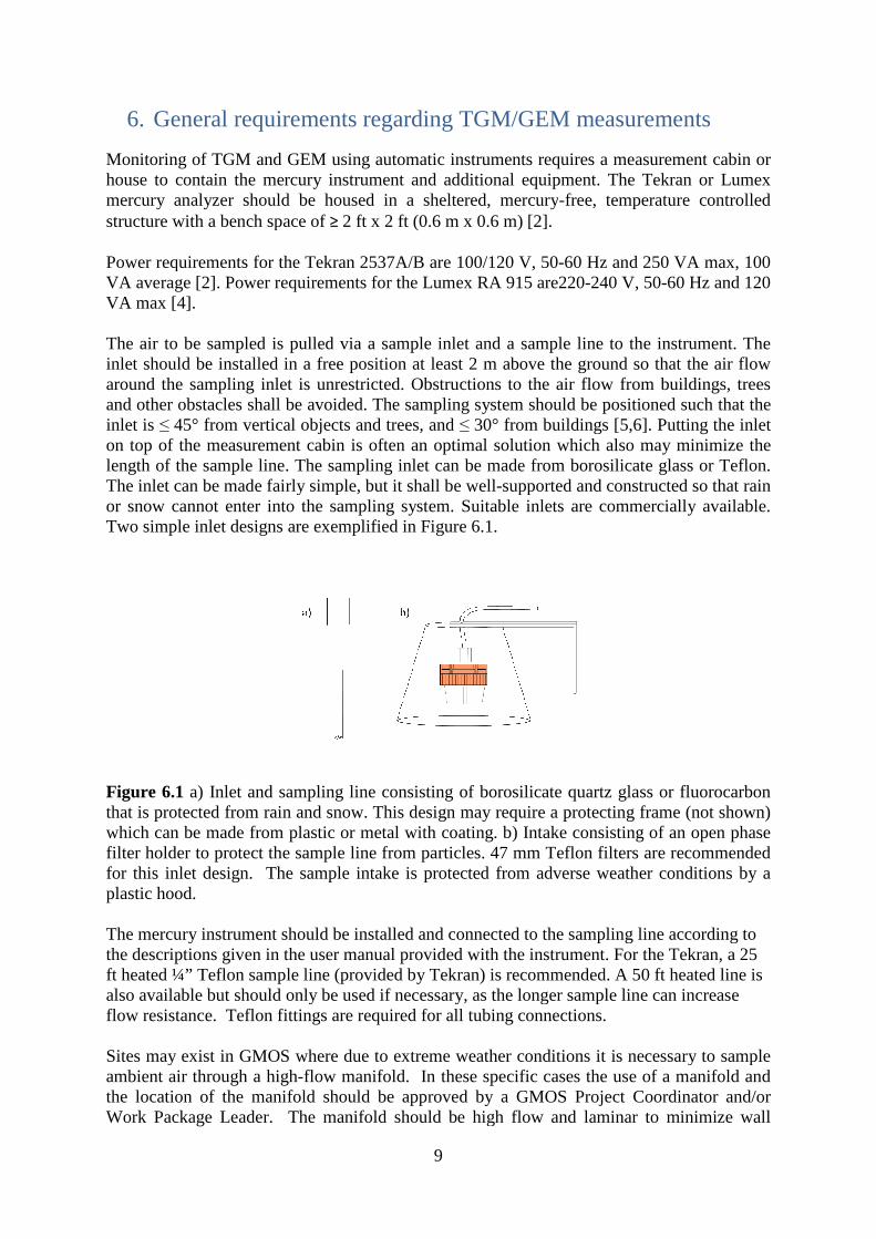
on top of the measurement cabin islength of the sample line. The sampling inlet can be made from borosilicate glassThe inlet can be made fairly simple, but it shall be wellor snow cannot enter into the sampling system. Suitable inlets are commercially available. Two simple inlet designs are exemplified in Figure 6.1.
Figure 6.1 a) Inlet and sampling line consisting of borosilicate quartz glass or fluorocarbon that is protected from rain and snow. This design may require a protecting frame (not shown) which can be made from plastic or metal with coating. b) Intake consisting of an open phase filter holder to protect the sample line from particles. for this inlet design. The sample plastic hood.
The mercury instrument should be installed and connected to the sampling line according to the descriptions given in the user manual provided wift heated ¼” Teflon sample line (provided by Tekran) is recommended. also available but should only be used if necessary, as the longer sample line can increase flow resistance. Teflon fitting Sites may exist in GMOS where due to extreme weather conditions it is necessary to sample ambient air through a high-flow manifold. In these specific cases the use of a manifold and the location of the manifold Work Package Leader. The manifold should be high flow and laminar to minimize wall
9
General requirements regarding TGM/GEM measurements
Monitoring of TGM and GEM using automatic instruments requires a measurement cabin or house to contain the mercury instrument and additional equipment. The
should be housed in a sheltered, mercury-free, temperature controllstructure with a bench space of ≥ 2 ft x 2 ft (0.6 m x 0.6 m) [2].
Power requirements for the Tekran 2537A/B are 100/120 V, 50-60 Hz and 250 VA max, 100 VA average [2]. Power requirements for the Lumex RA 915 are220-240 V, 50
The air to be sampled is pulled via a sample inlet and a sample line to the instrument. The inlet should be installed in a free position at least 2 m above the ground so that the air flow around the sampling inlet is unrestricted. Obstructions to the air flow from buildings, trees and other obstacles shall be avoided. The sampling system should be positioned such that the
≤ 45° from vertical objects and trees, and ≤ 30° from buildings [5,6on top of the measurement cabin is often an optimal solution which also may minimi
The sampling inlet can be made from borosilicate glassThe inlet can be made fairly simple, but it shall be well-supported and constructed so that rain
not enter into the sampling system. Suitable inlets are commercially available. Two simple inlet designs are exemplified in Figure 6.1.
a) Inlet and sampling line consisting of borosilicate quartz glass or fluorocarbon rom rain and snow. This design may require a protecting frame (not shown)
which can be made from plastic or metal with coating. b) Intake consisting of an open phase filter holder to protect the sample line from particles. 47 mm Teflon filters are recommen
sample intake is protected from adverse weather conditions
The mercury instrument should be installed and connected to the sampling line according to the descriptions given in the user manual provided with the instrument. For the Tekran, a ft heated ¼” Teflon sample line (provided by Tekran) is recommended. A 50 ft heated line is also available but should only be used if necessary, as the longer sample line can increase
Teflon fittings are required for all tubing connections.
Sites may exist in GMOS where due to extreme weather conditions it is necessary to sample flow manifold. In these specific cases the use of a manifold and
the location of the manifold should be approved by a GMOS Project Coordinator and/or . The manifold should be high flow and laminar to minimize wall
General requirements regarding TGM/GEM measurements
Monitoring of TGM and GEM using automatic instruments requires a measurement cabin or house to contain the mercury instrument and additional equipment. The Tekran or Lumex
free, temperature controlled
60 Hz and 250 VA max, 100 240 V, 50-60 Hz and 120
The air to be sampled is pulled via a sample inlet and a sample line to the instrument. The inlet should be installed in a free position at least 2 m above the ground so that the air flow
air flow from buildings, trees and other obstacles shall be avoided. The sampling system should be positioned such that the
6]. Putting the inlet often an optimal solution which also may minimize the
The sampling inlet can be made from borosilicate glass or Teflon. supported and constructed so that rain
not enter into the sampling system. Suitable inlets are commercially available.
a) Inlet and sampling line consisting of borosilicate quartz glass or fluorocarbon rom rain and snow. This design may require a protecting frame (not shown)
which can be made from plastic or metal with coating. b) Intake consisting of an open phase filters are recommended
from adverse weather conditions by a
The mercury instrument should be installed and connected to the sampling line according to For the Tekran, a 25 A 50 ft heated line is
also available but should only be used if necessary, as the longer sample line can increase
Sites may exist in GMOS where due to extreme weather conditions it is necessary to sample flow manifold. In these specific cases the use of a manifold and
a GMOS Project Coordinator and/or . The manifold should be high flow and laminar to minimize wall
10
effects. Glass or Teflon manifolds are acceptable. It is advisable that the inlet be positioned ~ 2 m above the shelter height and a 10 µm particulate cut size is suggested. The measurement device (e.g. Tekran or Lumex) should sample from the primary manifold air flow. The measurement device should be connected to the manifold by Teflon tubing. The manifold should be temperature controlled, and the Teflon line from the manifold to the measurement device can be unheated depending on the specific reason for using the manifold at any given site. It is recommended that a filter be installed between the manifold and measurement device to remove any remaining particles from the airstream prior to sampling by the measurement device. Teflon filters (0.2 um pore size, 47 mm) are recommended. It is recommended that the site operators occasionally (e.g. every 3 months) monitor the GEM concentration inside the monitoring shelter to determine whether there is any risk of contamination or bias from within the shelter. Shelter air should contain < 15 ng/m3 of Hg. Trace metal clean techniques must be used at all times in the laboratory and in the field when handling or preparing supplies and performing necessary tasks for ambient mercury sampling. Clean techniques are critical for preventing the contamination of sampling equipment and ensuring the collection of the highestquality data. This includes wearing appropriate clean, non-talc gloves (e.g. nitrile) when handling any component that will come in contact with the sampling stream. In the laboratory, such components should be handled in a clean room, clean bench, or glove box to avoid exposure to contaminated air.
7. Operation and routine maintenance of the Tekran and Lumex systems
Site operators are strongly encouraged to read the Tekran or Lumex operating manuals which accompany their instruments in order to fully understand how the instrument works and what steps are required to maintain the functionality of the instrument. This is especially important for new operators who are using these instruments for the first time. The guidelines below are intended to assist the operator with installing the instrument and maintaining it over time to ensure the collection of the highest quality data within the GMOS project.
7.1 Recommended instrument settings for the Tekran model 2537A/B instrument The parameter settings recommended at a typical background site are listed below. The Autocal feature should be set to “Yes” to indicate that the internal permeation source used for automatic calibrations is chosen (See section 7.5 below). Note that the sample timing in Table 7.1.1 could be optimized for more remote sites where it is difficult to obtain Argon (e.g. longer sampling time to reduce the frequency of Argon usage). However, more frequent heating is better for the gold cartridges and as such Tekran recommends a 5-minute sampling interval. As such, 5-minute sampling is recommended for the majority of GMOS sites.

11
Table 7.1.1 Recommended parameter settings for the Tekran model 2537A/B instrument
Method. Edit. Timing-1 Sample: 300 s FlushHi: 40 s Calib: 300 s Meas-dly: 5 s Zero-sub: No (a) BL-Time: 20 s
Method. Edit. Timing-2
Intg-Dly: 15 s Pk-Time: 35 s HtADur: 32 s Cool-Dn: 80 s HtBDur: 32 s Round: 5min
Method. Edit. other
Car-Meas: 80 ml/ min SmplRate: 1.00 l/min Car-Idle: 5 ml/ min WarmA: 3 % CarFlush: 100 ml/ min Warm B: 3 %
Method. Edit. Perm-Src
Autocal: No/Yes PermTime: 120sec Cal-Conc: Instrument specific CalibInt: 71.0 hr
(a) Zero-sub should be set to “No”. During normal performance the zero values (BlArea) should be very low(< 1500). If high zero values persist it might indicate problems with leaking or contamination. Consult the Tekran manual for appropriate maintenance
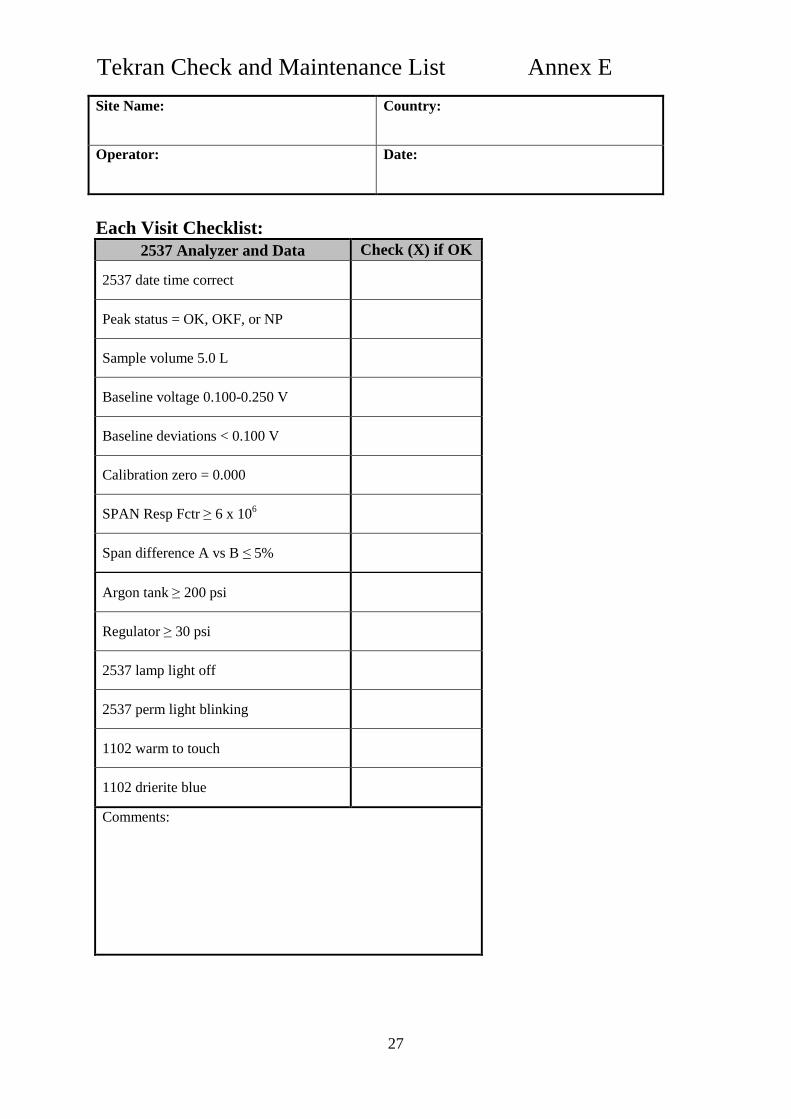
7.2 Maintenance procedures for the Tekran model 2537A/B instrument To assure collection of the highest quality data, the instrument must be inspected and maintained on a regular basis. A trained operator must visit the measurement site weekly. In addition, remote monitoring of the data is recommended where possible, as it allows for observing the performance of the instrument in between visits to the measurement site. A weekly site checklist to be used by the field operator is given in Annex E. The operator should bring this document to the site each week and appropriately note the maintenance performed. A brief summary of the primary features of the Tekran 2537 that require regular attention are provided here, and the specific maintenance procedures are described in 7.2.1-7.2.5: Lamp voltage – the intensity of the mercury lamp inside the 2537 analyzer should be checked regularly to ensure that it maintains a relatively constant value. The lamp voltage can be checked on the lamp circuit board and a red light on the front panel indicates when an adjustment is required. Baseline and baseline deviation – the baseline voltage and deviation indicate the performance of the instrument electronics, and these values are displayed on the front instrument panel as well as in the output data. The baseline should maintain a consistent small positive value. A large baseline deviation or noisy baseline could indicate problems with the lamp or other electronics.
12
Gold trap performance – ambient mercury is continuously analyzed on alternating A and B gold bead traps. Mercury is released from the traps when they are heated by the trap heating coils. It is important that the A and B traps demonstrate consistent concentration measurements. Oscillating concentrations values could indicate a problem with one of the traps or heating coils. Flow rate – the 2537 pump will be set to a constant flow rate. The actual flow rate should be monitored to ensure that the pump is functioning correctly and the correct amount of ambient air is being sampled. Argon tank pressure – mercury is carried from the gold traps to the analyzer using Argon gas. The 2537 will cease sampling and go into Idle mode if the Argon pressure decreases to less than 200 psi (1400 kPa). Therefore, the tank pressure should be monitored regularly and the tank should be replaced before it is empty. Calibration – the instrument is regularly calibrated by an internal permeation source to ensure that the traps and analyzer are operating consistently. The calibration consists of a zero and span (known amount of mercury released from the permeation source) for each trap. Each calibration result must be examined to assure that it can be used to determine TGM values of high analytical quality.
7.2.1 Weekly maintenance (Each visit)
Each week the operator is responsible for the following primary tasks to maintain the performance of the Tekran 2537:
Complete weekly site report Examine instrument data and parameters (e.g. sample volume, baseline voltage,
zero air flush values, peak status, argon tank, temperatures, error lights, etc.) and note on checklist
Confirm that the 2537 baseline level is between 0.100 - 0.250V Confirm that the standard deviation of the baseline is < 0.100 mV Check the 2537 lamp voltage Examine a recent period of consistent data collection without any obvious
disturbances (e.g. sudden peaks in concentration). Compute the average of 5 consecutive A trap concentrations and 5 consecutive B trap concentrations. Confirm that the average concentrations of the 5 consecutive the A/B trap measurements are different by < 10%.
For example: mean (A)= Average (A1, A2, A3, A4, A5) mean (B) = Average (B1, B2, B3, B4, B5) APD=[mean(A) –mean(B)]/Average[mean(A)+mean(B)] Where “APD” = Average Percent Difference Examine the every 71-hour internal automatic calibrations – confirm that the
calibration zeros are 0.000 and that the A and B trap spans are different by ≤ 5% NOTE: If the trap spans differ by 5-10%, the operator does not
necessarily need to take action but he/she should note this difference in the event that the traps continue to differ by a greater percentage or in the event that there is a sudden change in trap performance. If the trap spans differ by more than 10% then the operator may need to take corrective action and should consult the Tekran 2537 manual for guidance.
Examine the argon tank and regulator pressures Confirm that all error lights are off, the Perm light is blinking, and all switches are
in the correct position

13
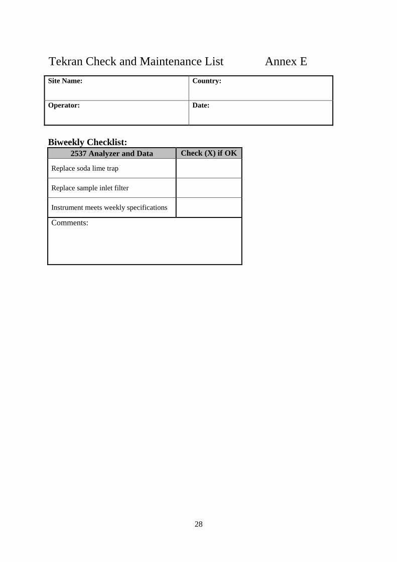
7.2.2 Bi-weekly Maintenance Bi-weekly the operator is responsible for the following tasks in addition to the weekly tasks:
Replace soda lime trap Replace sample inlet particulate filter (0.2 um pore size, 47 mm diameter) Confirm that the instrument meets all specifications
NOTE: Sites with high humidity (e.g. coastal and marine sites) may require the soda lime trap to be changed weekly instead of bi-weekly. All new sites should initially follow the guidelines above, but consider adjusting the frequency of soda lime change once initial data is collected and site specific procedures can be determined.
7.2.3 Quarterly maintenance
The operator is responsible for the following tasks on a quarterly basis in addition to the weekly and bi-weekly tasks described in 7.2.1 and 7.2.2. Note that not all tasks listed below are performed every quarter so it is important that the operator pay attention to when these procedures are required: Each Quarter:
Check sample line for recovery and leaks (see section 10.20 of the Tekran 2537 manual or Tekran Technical Note TN2537_210).
Perform elemental injections on gold trap cartridges A and B (see section 7.5 for explanation; see Annex A for instructions on the use of the mercury vapor source for elemental injections)
Examine gold cartridge heating coils and confirm that they are bright orange when heating
Confirm that instrument shelter air contains ≤ 15 ng/m3 of mercury Install new 2537sample filter Clean Teflon line from 2537 to soda lime trap Perform leak check of the 2537 analyzer. This can be done by disconnecting the
sample line from the back of the instrument (where the filter housing is located) and physically blocking the filter inlet with a Teflon cap. The pump flow should drop to zero (pump will begin to race). At that time the Teflon cap can be removed and sample line can be reattached.
2nd Quarter only: Measure, verify, and calculate % difference of the 2537 flow rate Verify 2537 scalefactor
4th Quarter only: Change 2537 heater coils, zero air canister, DFU filter Measure, verify, and calculate % difference of the 2537 flow rate Verify 2537 scalefactor Calibrate fow meter Rinseheatedsampleline Verify standard addition performance Site audit (See section 9)
14
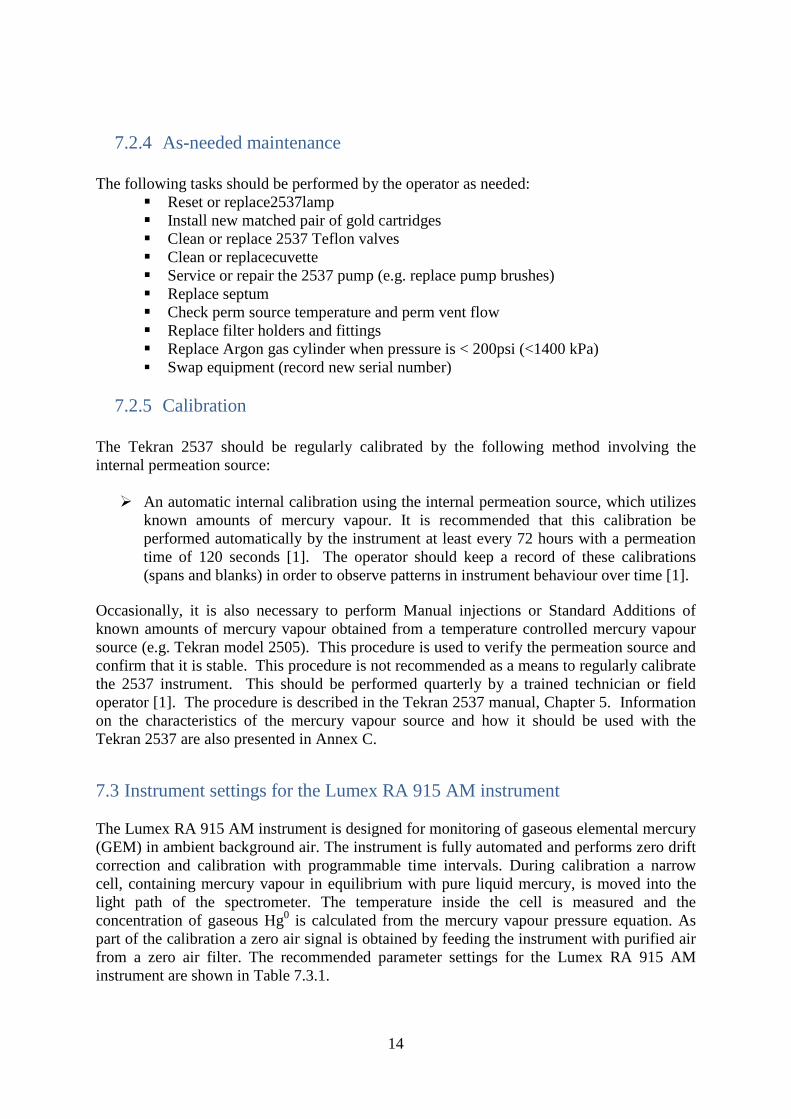
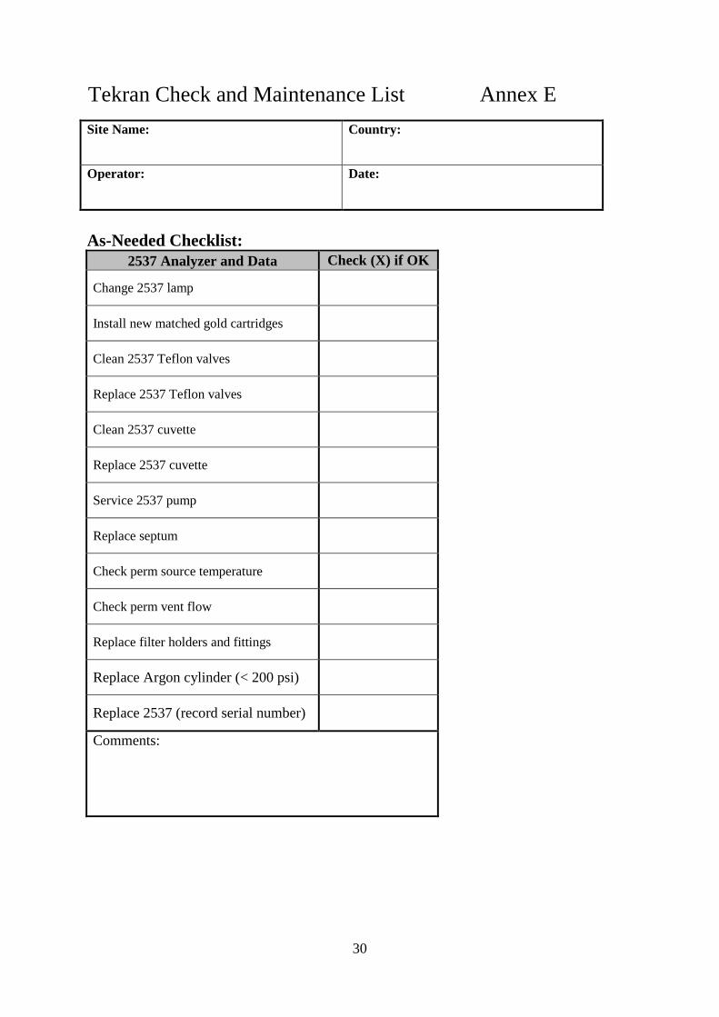
7.2.4 As-needed maintenance
The following tasks should be performed by the operator as needed: Reset or replace2537lamp Install new matched pair of gold cartridges Clean or replace 2537 Teflon valves Clean or replacecuvette Service or repair the 2537 pump (e.g. replace pump brushes) Replace septum Check perm source temperature and perm vent flow Replace filter holders and fittings Replace Argon gas cylinder when pressure is < 200psi (<1400 kPa) Swap equipment (record new serial number)
7.2.5 Calibration
The Tekran 2537 should be regularly calibrated by the following method involving the internal permeation source:
An automatic internal calibration using the internal permeation source, which utilizes known amounts of mercury vapour. It is recommended that this calibration be performed automatically by the instrument at least every 72 hours with a permeation time of 120 seconds [1]. The operator should keep a record of these calibrations (spans and blanks) in order to observe patterns in instrument behaviour over time [1].
Occasionally, it is also necessary to perform Manual injections or Standard Additions of known amounts of mercury vapour obtained from a temperature controlled mercury vapour source (e.g. Tekran model 2505). This procedure is used to verify the permeation source and confirm that it is stable. This procedure is not recommended as a means to regularly calibrate the 2537 instrument. This should be performed quarterly by a trained technician or field operator [1]. The procedure is described in the Tekran 2537 manual, Chapter 5. Information on the characteristics of the mercury vapour source and how it should be used with the Tekran 2537 are also presented in Annex C.
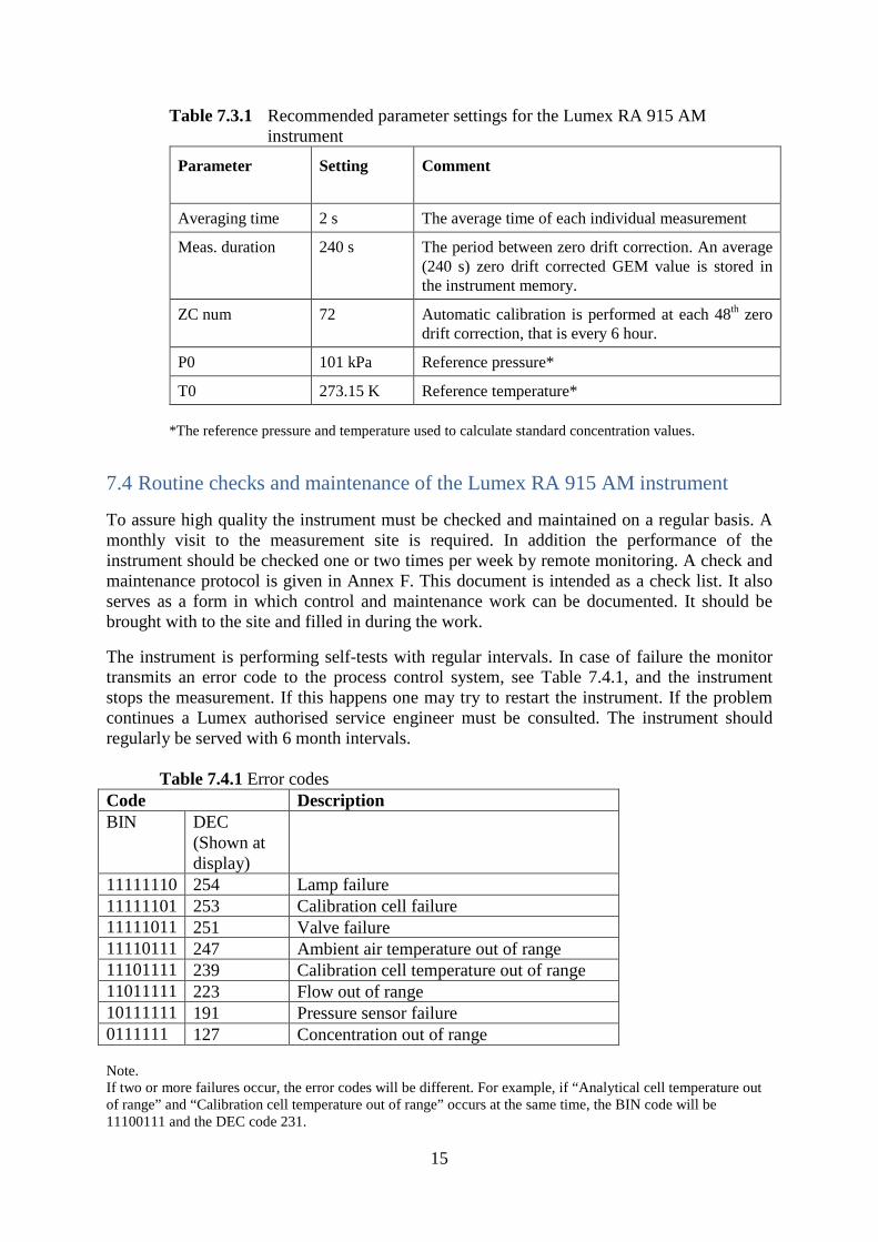
7.3 Instrument settings for the Lumex RA 915 AM instrument The Lumex RA 915 AM instrument is designed for monitoring of gaseous elemental mercury (GEM) in ambient background air. The instrument is fully automated and performs zero drift correction and calibration with programmable time intervals. During calibration a narrow cell, containing mercury vapour in equilibrium with pure liquid mercury, is moved into the light path of the spectrometer. The temperature inside the cell is measured and the concentration of gaseous Hg0 is calculated from the mercury vapour pressure equation. As part of the calibration a zero air signal is obtained by feeding the instrument with purified air from a zero air filter. The recommended parameter settings for the Lumex RA 915 AM instrument are shown in Table 7.3.1.
15
Table 7.3.1 Recommended parameter settings for the Lumex RA 915 AM instrument
Parameter
Setting Comment
Averaging time 2 s The average time of each individual measurement
Meas. duration 240 s The period between zero drift correction. An average (240 s) zero drift corrected GEM value is stored in the instrument memory.
ZC num 72 Automatic calibration is performed at each 48th zero drift correction, that is every 6 hour.
P0 101 kPa Reference pressure*
T0 273.15 K Reference temperature* *The reference pressure and temperature used to calculate standard concentration values.
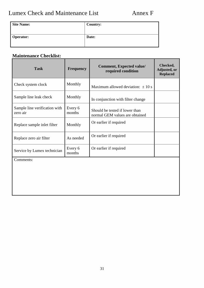
7.4 Routine checks and maintenance of the Lumex RA 915 AM instrument
To assure high quality the instrument must be checked and maintained on a regular basis. A monthly visit to the measurement site is required. In addition the performance of the instrument should be checked one or two times per week by remote monitoring. A check and maintenance protocol is given in Annex F. This document is intended as a check list. It also serves as a form in which control and maintenance work can be documented. It should be brought with to the site and filled in during the work.
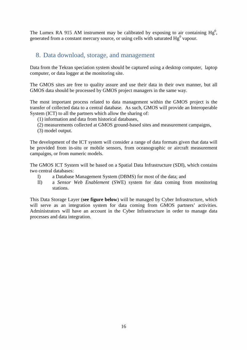
The instrument is performing self-tests with regular intervals. In case of failure the monitor transmits an error code to the process control system, see Table 7.4.1, and the instrument stops the measurement. If this happens one may try to restart the instrument. If the problem continues a Lumex authorised service engineer must be consulted. The instrument should regularly be served with 6 month intervals. Table 7.4.1 Error codes Code Description BIN DEC
(Shown at display)
11111110 254 Lamp failure 11111101 253 Calibration cell failure 11111011 251 Valve failure 11110111 247 Ambient air temperature out of range 11101111 239 Calibration cell temperature out of range 11011111 223 Flow out of range 10111111 191 Pressure sensor failure 0111111 127 Concentration out of range Note. If two or more failures occur, the error codes will be different. For example, if “Analytical cell temperature out of range” and “Calibration cell temperature out of range” occurs at the same time, the BIN code will be 11100111 and the DEC code 231.
16
The Lumex RA 915 AM instrument may be calibrated by exposing to air containing Hg0, generated from a constant mercury source, or using cells with saturated Hg0 vapour.
8. Data download, storage, and management Data from the Tekran speciation system should be captured using a desktop computer, laptop computer, or data logger at the monitoring site. The GMOS sites are free to quality assure and use their data in their own manner, but all GMOS data should be processed by GMOS project managers in the same way. The most important process related to data management within the GMOS project is the transfer of collected data to a central database. As such, GMOS will provide an Interoperable System (ICT) to all the partners which allow the sharing of:
(1) information and data from historical databases, (2) measurements collected at GMOS ground-based sites and measurement campaigns, (3) model output.
The development of the ICT system will consider a range of data formats given that data will be provided from in-situ or mobile sensors, from oceanographic or aircraft measurement campaigns, or from numeric models. The GMOS ICT System will be based on a Spatial Data Infrastructure (SDI), which contains two central databases:
I) a Database Management System (DBMS) for most of the data; and II) a Sensor Web Enablement (SWE) system for data coming from monitoring
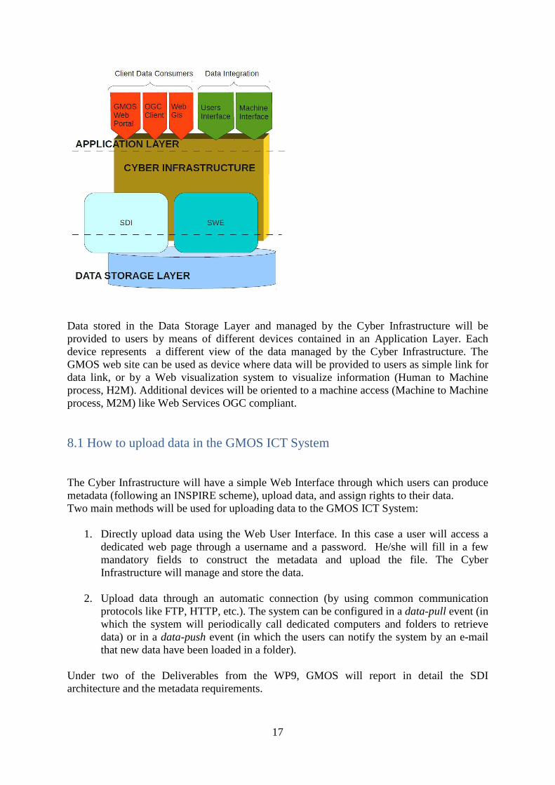
stations. This Data Storage Layer (see figure below) will be managed by Cyber Infrastructure, which will serve as an integration system for data coming from GMOS partners’ activities. Administrators will have an account in the Cyber Infrastructure in order to manage data processes and data integration.
17
Data stored in the Data Storage Layer and managed by the Cyber Infrastructure will be provided to users by means of different devices contained in an Application Layer. Each device represents a different view of the data managed by the Cyber Infrastructure. The GMOS web site can be used as device where data will be provided to users as simple link for data link, or by a Web visualization system to visualize information (Human to Machine process, H2M). Additional devices will be oriented to a machine access (Machine to Machine process, M2M) like Web Services OGC compliant. 8.1 How to upload data in the GMOS ICT System The Cyber Infrastructure will have a simple Web Interface through which users can produce metadata (following an INSPIRE scheme), upload data, and assign rights to their data. Two main methods will be used for uploading data to the GMOS ICT System:
1. Directly upload data using the Web User Interface. In this case a user will access a dedicated web page through a username and a password. He/she will fill in a few mandatory fields to construct the metadata and upload the file. The Cyber Infrastructure will manage and store the data.
2. Upload data through an automatic connection (by using common communication protocols like FTP, HTTP, etc.). The system can be configured in a data-pull event (in which the system will periodically call dedicated computers and folders to retrieve data) or in a data-push event (in which the users can notify the system by an e-mail that new data have been loaded in a folder).
Under two of the Deliverables from the WP9, GMOS will report in detail the SDI architecture and the metadata requirements.
18
9. Quality control and quality assurance Laboratories involved in preparing supplies for operation of the TGM/GEM monitoring instruments must demonstrate adherence to quality control and assurance procedures. Site operators should also be thoroughly trained by a technician or GMOS project coordinator who is familiar with the operation of the instrumentation. The operator is responsible for reviewing all Standard Operating Procedures, troubleshooting guides, and site maintenance documents provided. The analyzer must also be calibrated regularly as described previously. The site operator is responsible for evaluating the raw instrument data on a weekly basis. Any abnormalities should be noted on the weekly field sheet, and as necessary the site operator should troubleshoot and perform instrument maintenance to resolve any persistent problems. Regular Site Audits Regular site audits by a trained technician are recommended in order to ensure continued instrument performance and the collection of high quality data. The following procedures are recommended during regular (e.g. annual or bi-annual) site audits [2]: General site inspection:
Verify overall operation of the equipment Inspect area around the station and confirm compliance with siting criteria Determine height of sample inlet Identify location of sample inlet with respect to the laboratory building Identify type and size of inlet hood Identify type and length of sample line Observe movement of people and vehicles near site
Instrument inspection: Determine sample volume Check for contamination of sample line and sample filter Inspect sample line integrity
The following checks apply to the Tekran 2537 only: Leak test on each gold cartridge Determine difference between cartridges (expect difference within 10%) Permeation source check Cartridge integrity and interference Verify performance of the Standard Addition Unit (calibration unit should
stabilize overnight before injections are performed) Compare performance of syringes Compare calibration set-ups
The GMOS team will regularly and systematically perform QA/QC procedures on the speciated ambient Hg measurements collected at all sites. The QA/QC procedure will be designed to generate error flags for problematic data. This systematic examination of the data over time will allow for determining the benchmarks for high quality data within the GMOS project. Through frequent and systematic examination of the data it will also be possible to ensure that the site operators are operating the instrumentation correctly and collecting consistent high quality data. The quality of performance at each site will be in part determined by the percentage of complete data that is collected, which will be determined by the presence of complete sampling cycles free of instrument or measurement error.

19
Throughout the course of the project, GMOS will work with other networks such as AMNet to determine appropriate detection limits for measurement parameters as well as acceptable limits of precision and uncertainty, because widely accepted values have not currently been established for measurements with the Tekran speciation system.
10. References
[1] NEN-EN 15852 (en). Ambient air quality - Standard method for the determination of mercury deposition. ICS 13.040.20, June 2010. [2] Standard Operating Procedures Manual for Total Gaseous Mercury Measurements.
Canadian Atmospheric Mercury Measurement Network (CAMNET).Version 4.0 March 1999. Written and edited by Sandy Steffen and Bill Schroeder.
[3] Model 2537B Ambient Mercury Vapour Analyzer User Manual. Rev: 3.11, October 2008. Tekran Instruments Corporation. [4] RA – 915 AM Ambient Air Mercury Monitor Operation Manual. RA-915 Rev A-3, December 2007. Lumex Ltd. [5] Manual for the GAW precipitation programme. Guidelines, Data Quality Objectives
and Standard Operating Procedures. WMO TD No. 1251. WMO/GAW Report nr 160.WMO, 2004.
[6] NADP Site Selection and Installation Manual. September 2009. Written by Mark F.
Rhodes.
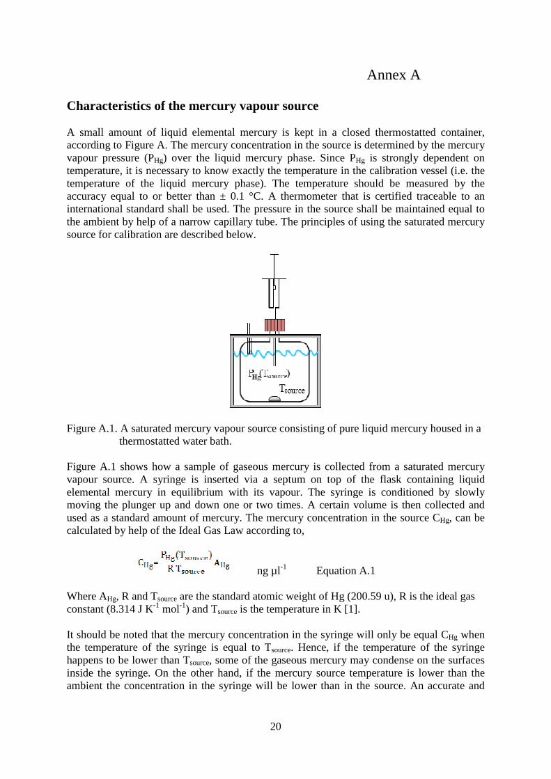
Characteristics of the mercury vapour source A small amount of liquid elemental mercury is kept in a closed thermostatted container, according to Figure A. The mercurvapour pressure (PHg) over the liquid mercury phase. Since temperature, it is necessary to know exactly the temperature in the calibration vessel (i.e. the temperature of the liquid mercury phase). The temperature should be measured by the accuracy equal to or better than ± 0.1 °C. A therinternational standard shall be used. The pressure in the source shall be maintained equal to the ambient by help of a narrow capillary tube. The principles of using the saturated mercury source for calibration are described below.
Figure A.1. A saturated mercury vapour source consisting of pure liquid mercury housed in a thermostatted water bath. Figure A.1 shows how a sample of gaseous mercury is collected from a saturated mercury vapour source. A syringe is elemental mercury in equilibrium with its vapour. The syringe is conditioned by slowly moving the plunger up and down one or two times. A certain volume is then collected and used as a standard amount of mercury. The mercury concentration in the source Ccalculated by help of the Ideal Gas Law according to,
Where AHg, R and Tsource are the standard atomic weight of Hg (200.59 u), Rconstant (8.314 J K-1 mol-1) and T It should be noted that the mercury concentration in the syringe will only be equal Cthe temperature of the syringe is equal to Thappens to be lower than Tsource
inside the syringe. On the other hand, if the mercury source temperature is lower than the ambient the concentration in the syringe will be lower than in the source.
20
Annex A
Characteristics of the mercury vapour source
A small amount of liquid elemental mercury is kept in a closed thermostatted container, according to Figure A. The mercury concentration in the source is determined by the mercury
) over the liquid mercury phase. Since PHg is strongly dependent on temperature, it is necessary to know exactly the temperature in the calibration vessel (i.e. the temperature of the liquid mercury phase). The temperature should be measured by the accuracy equal to or better than ± 0.1 °C. A thermometer that is certified traceable to an international standard shall be used. The pressure in the source shall be maintained equal to the ambient by help of a narrow capillary tube. The principles of using the saturated mercury
described below.
Figure A.1. A saturated mercury vapour source consisting of pure liquid mercury housed in a thermostatted water bath.
Figure A.1 shows how a sample of gaseous mercury is collected from a saturated mercury inserted via a septum on top of the flask containing liquid
elemental mercury in equilibrium with its vapour. The syringe is conditioned by slowly moving the plunger up and down one or two times. A certain volume is then collected and
mount of mercury. The mercury concentration in the source Ccalculated by help of the Ideal Gas Law according to,
ng µl-1 Equation A.1
are the standard atomic weight of Hg (200.59 u), R) and Tsource is the temperature in K [1].
It should be noted that the mercury concentration in the syringe will only be equal Cthe temperature of the syringe is equal to Tsource. Hence, if the temperature of the syringe
source, some of the gaseous mercury may condense on the surfaces inside the syringe. On the other hand, if the mercury source temperature is lower than the ambient the concentration in the syringe will be lower than in the source.
Annex A
A small amount of liquid elemental mercury is kept in a closed thermostatted container, y concentration in the source is determined by the mercury
is strongly dependent on temperature, it is necessary to know exactly the temperature in the calibration vessel (i.e. the temperature of the liquid mercury phase). The temperature should be measured by the
mometer that is certified traceable to an international standard shall be used. The pressure in the source shall be maintained equal to the ambient by help of a narrow capillary tube. The principles of using the saturated mercury
Figure A.1. A saturated mercury vapour source consisting of pure liquid mercury housed in a
Figure A.1 shows how a sample of gaseous mercury is collected from a saturated mercury inserted via a septum on top of the flask containing liquid
elemental mercury in equilibrium with its vapour. The syringe is conditioned by slowly moving the plunger up and down one or two times. A certain volume is then collected and
mount of mercury. The mercury concentration in the source CHg, can be
are the standard atomic weight of Hg (200.59 u), R is the ideal gas
It should be noted that the mercury concentration in the syringe will only be equal CHg when . Hence, if the temperature of the syringe
, some of the gaseous mercury may condense on the surfaces inside the syringe. On the other hand, if the mercury source temperature is lower than the ambient the concentration in the syringe will be lower than in the source. An accurate and

precise correction for the temperature difference between the syringe and that of the source can be made [1] and the result is,
To use equation A.2, PHg (Tdescribes the saturation pressure of mercury. If using the expression proposed by Ebdon at al., 1989 [2], the following equation is obtained.
Tsyringe is the temperature of the syringeTsource is the temperature of the mercury source in Kelvin;A is a constant with numerical value B is a constant equal to 3 240.87;D is a constant equal to 3 216.523; Equation A.3 shall be used to calculate the mass concentrationsamples collected from a mercury vapour source using a syringe. Equation A.3 is identical to that recommended in the recent European Standard NEN15852 [1] and resembles the equations recommended in many mercury instrument manuals and standards. Remarks:
• Equation A.3 takes account of two different temperatures source and that of the syringe.
• Equation A.3 is only valid for situations where T
temperature of the mercury source (T
• It is recommended to keep the temperature of the mercury source at least some degrees Celsius below room temperature.
High accuracy is required for the determination of Tthe vapour pressure of mercury is exponentially dependent on temperature. Therefore, Tappears in the exponential term of Equation A.3. The temperature of the syringe can normally be considered as equal to the room temperature and it is enough to measure this tempwith an accuracy of ± 1 oC. References [1] NEN-EN 15853 (en).Ambient air quality deposition.ICS 13.040.20, June 2010. [2] Ebdon L.; Corns W. T.; Stockwell P. B.; Stockwell P.
adsorber/desorber system to monitor mercury description; Journal of Automa
21
precise correction for the temperature difference between the syringe and that of the source ] and the result is,
ng µl-1
(Tsource) must be substituted by a mathematical describes the saturation pressure of mercury. If using the expression proposed by Ebdon at al., 1989 [2], the following equation is obtained.
ng µl-1 (Tsyringe ≥ Tsource)
is the temperature of the syringe in Kelvin; is the temperature of the mercury source in Kelvin;
A is a constant with numerical value -8.134 46; 240.87; 216.523;
Equation A.3 shall be used to calculate the mass concentration of mercury vapour samples collected from a mercury vapour source using a syringe.
Equation A.3 is identical to that recommended in the recent European Standard NEN15852 [1] and resembles the equations recommended in many mercury instrument manuals
Equation A.3 takes account of two different temperatures – the temperature of the mercury source and that of the syringe.
Equation A.3 is only valid for situations where Tsyringe is equal to or higher than the mercury source (Tsource).
It is recommended to keep the temperature of the mercury source at least some degrees below room temperature.
High accuracy is required for the determination of Tsource as mentioned above. This is because ssure of mercury is exponentially dependent on temperature. Therefore, T
appears in the exponential term of Equation A.3. The temperature of the syringe can normally be considered as equal to the room temperature and it is enough to measure this temp
EN 15853 (en).Ambient air quality - Standard method for the determination of deposition.ICS 13.040.20, June 2010.
Ebdon L.; Corns W. T.; Stockwell P. B.; Stockwell P. M.; Application of a computeradsorber/desorber system to monitor mercury in air or gas samples: Part 1. Calibration and description; Journal of Automatic Chemistry (1989), Vol. 11, No 6, p. 247-253
precise correction for the temperature difference between the syringe and that of the source
Equation A.2
) must be substituted by a mathematical function that describes the saturation pressure of mercury. If using the expression proposed by Ebdon at
Equation A.3
of mercury vapour
Equation A.3 is identical to that recommended in the recent European Standard NEN-EN 15852 [1] and resembles the equations recommended in many mercury instrument manuals
the temperature of the mercury
is equal to or higher than the
It is recommended to keep the temperature of the mercury source at least some degrees
as mentioned above. This is because ssure of mercury is exponentially dependent on temperature. Therefore, Tsource
appears in the exponential term of Equation A.3. The temperature of the syringe can normally be considered as equal to the room temperature and it is enough to measure this temperature
method for the determination of mercury
M.; Application of a computer-controlled in air or gas samples: Part 1. Calibration and system

22
Characteristics of the Tekran 2505 mercury vapor source It is recommended that the Tekran Model 2505 Mercury Vapor Primary Calibration Unit be used to perform manual injections and standard additions on the 2537. With this instrument a small amount of liquid elemental mercury is kept in a closed thermoelectric temperature controlled container, and no water bath is needed. The mercury concentration in the source is determined by the mercury vapour pressure (PHg) over the liquid mercury phase. Since PHg is strongly dependent on temperature, it is necessary to know exactly the temperature in the calibration vessel (i.e. the temperature of the liquid mercury phase). The temperature of the source is determined automatically by the 2505 and reported digitally. The 2505 is powered by 110 V line power. The temperature resolution of 0.001 °C and an accuracy of ±0.05 °C. A Hamilton digital syringe is used to draw predetermined amounts of mercury vapour from the device. The concentration of mercury obtained by the syringe can be determined by the temperature of the mercury chamber. Manual injections and standard additions should be performed by a trained technician following the instructions in the Tekran 2505 User Manual.
Figure A.2.The Tekran 2505 Mercury Vapor Primary Calibration Unit

23
Annex B Cleaning of gold traps A pair of gold cartridges (gold traps), i.e. glass tubes containing a large gold surface, is used in the Tekran 2537 mercury analyser to trap gaseous mercury from ambient air. The two cartridges continuously undergo adsorption/desorption cycles during the measurements. After prolonged use, deactivation may occur. One option is to remove the gold traps and install a new matched pair (this is typically performed annually or as needed). In certain situations cleaning of the cartridges may be an alternatively suitable solution. A possible monthly standard cleaning procedure is presented here. To perform continuous mercury measurements two pairs of sample gold traps are required. After cleaning the cleaned gold traps should be tested against a reference pair of gold traps, i.e. an additional pair that is not used for sampling. If the tested cartridges show a deviation of more than 5 % a more profound treatment with Aqua regia (three parts of concentrated hydrochloric acid (HCl) and one part of concentrated nitric acid (HNO3) is needed. Cleaning procedure of gold cartridges in an ultrasonic bath Prior to cleaning the cartridges are rinsed with deionised water (3.5) using a clean syringe and immersed overnight in deionised water (3.5). The actual cleaning takes place the next day in an ultrasonic bath with a solution of deionised water (3.5) and an alkali detergent1. The solution consists of 300 ml of deionised water and 12 ml of the detergent. Use disposable (rubber) gloves during the whole procedure! The complete cleaning procedure: I a. With a 12 ml plastic syringe draw 10 ml of the solution into the cartridge and
immediately force it out again; repeat this procedure 10 times;
b. Fill the cartridge again with the solution and place in into the ultrasonic bath for 9 minutes;
Repeat procedure a. and b. 10 times for both cartridges (A and B). Make sure not to mix the cartridges. Finnish by rinsing with deionised water. II a. With a new 12 ml plastic syringe draw 10 ml of deionised water into the cartridge and
immediately forced it out again. Repeat this procedure at least 10 times using fresh deionised water each time.
24
b. Finnish the cleaning by flushing pure Argon or Nitrogen (3.1)/(3.2) gas through the cartridges. The Argon/Nitrogen gas should be flushed through each of the cartridges for at least 5 minutes.
Testing of the cleaned cartridge pair The cartridges are tested in a Tekran 2537A analyser (preferably with an analyser not used for sampling). In this test the adsorption capacity of the cleaned cartridges are compared with a reference gold cartridge pair that not is used for continuous sampling. Testing procedure Start background air sampling with the reference cartridge pair. The instrument should be run using the same frequency and timing that is normally used during sampling (5 min sampling cycles at a sampling rate of 1.0 L per min). Check the performance of the instrument, i.e. that it is yielding expected background TGM values and that the zero air values are sufficiently low (should be close to zero). a. Measure a sequence of five complete cycles on each cartridge;
b. Install the cleaned cartridge pair. Start the instrument and perform a zero air test. Measure
a sequence of five complete cycles on each cartridge. The average values from the cleaned cartridges should be within ± 5 when compared to each other and should also not differ more than 5 % in comparison to the reference cartridges. 1Labosol-U-Ultraschall-Reiniger. This detergent is provided by the German company neoLab (www.neolab.de).
25
Annex C Cleaning of equipment used for TGM/GEM measurements All parts that are in contact with the sample air shall be cleaned extensively before use. Plastic or nitrile non-talc gloves shall be used during all steps of the cleaning procedure. A suitable cleaning procedure is given below.
1) Wash with an alkaline detergent. Rinse thoroughly with ultrapure water
2) Leach with 2 % HCl (3.7) for at least 48 h. This can be done in a polyethylene tank.
3) Rinse thoroughly with ultrapure water (3.5) and dry in a clean laminar flow hood. Store the cleaned equipment in double plastic bags.

Recalculation of concentrations and air volumes to reference conditions TGM and GEM concentration values are presented as the mass of Hgactual air volumes vary with temperature and pressure, standardised volumes are used. With instruments using MFC and MFM the air volume is often standardised to a certain reference temperature and pressure. The default setting of, for exinstrument, is 273.15 K and 101325 Pa. Concentration values can easily be recalculated to a certain reference condition according to,
(ng m-
where Tref and Pref correspond to the desired reference condition and T, P and C relate to the actual temperature, pressure and concentration, respectively [concentrations obtained at varying temperature and pressure each individual value must be recalculated using Equation 7.1. Whereas when recalculating from one reference condition to another the relation between C Likewise, may a volumetric flow rate value be recalculated to a standardised flow rate, according to,
where Tref and Pref correspond to the desired reference condition and T, P and F relate to the actual temperature, pressure and volumetric flow rate, respectively [ The GMOS reference temperature and pressure are 273.15 K
26
Annex D
Recalculation of concentrations and air volumes to reference conditions
TGM and GEM concentration values are presented as the mass of Hg0 actual air volumes vary with temperature and pressure, standardised volumes are used. With instruments using MFC and MFM the air volume is often standardised to a certain reference temperature and pressure. The default setting of, for example the Tekran model 2537A/B instrument, is 273.15 K and 101325 Pa. Concentration values can easily be recalculated to a certain reference condition according to,
-3) Equation D.1
correspond to the desired reference condition and T, P and C relate to the actual temperature, pressure and concentration, respectively [1]. To convert GEM concentrations obtained at varying temperature and pressure each individual value must be
ted using Equation 7.1. Whereas when recalculating from one reference condition to another the relation between Cref and C is a constant.
Likewise, may a volumetric flow rate value be recalculated to a standardised flow rate,
Equation D.2
correspond to the desired reference condition and T, P and F relate to the actual temperature, pressure and volumetric flow rate, respectively [1].
The GMOS reference temperature and pressure are 273.15 K and 101325 Pa, respectively.
Annex D
Recalculation of concentrations and air volumes to reference conditions
per volume. Since actual air volumes vary with temperature and pressure, standardised volumes are used. With instruments using MFC and MFM the air volume is often standardised to a certain reference
ample the Tekran model 2537A/B instrument, is 273.15 K and 101325 Pa. Concentration values can easily be recalculated to a
correspond to the desired reference condition and T, P and C relate to the ]. To convert GEM
concentrations obtained at varying temperature and pressure each individual value must be ted using Equation 7.1. Whereas when recalculating from one reference condition to
Likewise, may a volumetric flow rate value be recalculated to a standardised flow rate,
correspond to the desired reference condition and T, P and F relate to the
and 101325 Pa, respectively.
27
Site Name: Country:
Operator: Date:
Each Visit Checklist:
2537 Analyzer and Data Check (X) if OK
2537 date time correct
Peak status = OK, OKF, or NP
Sample volume 5.0 L
Baseline voltage 0.100-0.250 V
Baseline deviations < 0.100 V
Calibration zero = 0.000
SPAN Resp Fctr ≥ 6 x 10⁶
Span difference A vs B ≤ 5%
Argon tank ≥ 200 psi
Regulator ≥ 30 psi
2537 lamp light off
2537 perm light blinking
1102 warm to touch
1102 drierite blue
Comments:
Tekran Check and Maintenance List Annex E
28
Site Name: Country:
Operator: Date:
Biweekly Checklist:
2537 Analyzer and Data Check (X) if OK
Replace soda lime trap
Replace sample inlet filter
Instrument meets weekly specifications
Comments:
Tekran Check and Maintenance List Annex E

29
Site Name: Country:
Operator: Date:
Quarterly Checklist:
Each Quarter Check (X) if OK or Insert Value Second Quarter Check (X) if OK
or Insert Value
Sample line leak check 2537 flow rate, instrument (lpm)
Cartridge A, mass injected (pg) 2537 flow rate, measured (lpm)
Cartridge A concentration (pg/m3) 2537 flow rate, % difference (%)
Cartridge A, manual injection % difference 2537 scale factor
Cartridge B, mass injected (pg) Fourth Quarter Check (X) if OK or Insert Value
Cartridge B concentration (pg/m3) Change 2537 heater coils
Cartridge B, manual injection % difference Change 2537 zero air canister
Trap heating coils bright orange Change 2537 DFU filter
Instrument shelter air ≤ 15 ng/m3 2537 flow rate, instrument (lpm)
Change 2537 sample filter 2537 flow rate, measured (lpm)
Clean Teflon line from 2537 to soda lime 2537 flow rate, % difference (%)
2537 leak check 2537 scale factor
Rinse heated sample line
Comments:
Tekran Check and Maintenance List Annex E
30
Site Name: Country:
Operator: Date:
As-Needed Checklist:
2537 Analyzer and Data Check (X) if OK
Change 2537 lamp
Install new matched gold cartridges
Clean 2537 Teflon valves
Replace 2537 Teflon valves
Clean 2537 cuvette
Replace 2537 cuvette
Service 2537 pump
Replace septum
Check perm source temperature
Check perm vent flow
Replace filter holders and fittings
Replace Argon cylinder (< 200 psi)
Replace 2537 (record serial number)
Comments:
Tekran Check and Maintenance List Annex E
31
Site Name: Country:
Operator: Date:
Maintenance Checklist:
Task Frequency Comment, Expected value/
required condition Checked,
Adjusted, or Replaced
Check system clock Monthly Maximum allowed deviation: ± 10 s
Sample line leak check Monthly In conjunction with filter change
Sample line verification with zero air
Every 6 months
Should be tested if lower than normal GEM values are obtained
Replace sample inlet filter Monthly
Or earlier if required
Replace zero air filter As needed Or earlier if required
Service by Lumex technician Every 6 months
Or earlier if required
Comments:
Lumex Check and Maintenance List Annex F

32