
GHK TalkStory WHOIS = 2032, Gordon Kraft owns TalkStory.com = 2032

G e o r g e M a s s e n b u r g L a b s
GML 2032 Microphone Preamplifier /Parametric Equalizer
The Model 2032 Microphone Preamplifier / Parametric Equalizer is a single-channel,multi-input device for high-resolution studio and remote applications. Incorporating therenowned 8300 preamplifier and reference-standard 8200 equalizer, the Model 2032inherits over thirty years of GML engineering excellence. This transparent class-Adiscrete design with internal supply delivers reliability, musicality, and precision.
Owner's ManualVersion 1.0August, 2004
All materials herein © George Massenburg Labs, LLC.
GML, LLC.Franklin, TN USA615.790.9946 (ph)www.massenburg.com

Combining the features of the GML flagship 8200 Parametric Equalizer and 8300Transformerless Microphone Preamplifier, the Model 2032 embodies the legendarydetail and accuracy for which GML is renowned. The power and functionality of theserevolutionary processors is further coupled with the addition of a front panel musicalinstrument input, two position high-pass filter, front panel phantom and phase switching,and flexible routing options while maintaining the GML standard of performance andtransparency. These advanced circuits, envisioned by George Massenburg, havebenefited from over 30 years of research, limited manufacturing, critical listeninganalysis, widespread usage by demanding industry professionals, and continuousevaluation by the GML Engineering Department.
The GML Model 2032 Microphone Preamplifier / Parametric Equalizer derives its powerand flexibility in large part from its features:
•• All-discrete, Class-A design; no integrated circuits to compromise theaudio path
•• DC-servo and premium-grade film coupling; no interstage capacitors toadd distortion or degrade over time; no tantalum electrolytic, ceramic, oraluminum electrolytic capacitors in the signal path*
•• Transformerless; precision electronically balanced inputs
•• Designed with GML 9202 (single) and GML 8501 (dual-differential) low-noise, low-distortion, wide dynamic range, wide bandwidth precisiondiscrete opamps
•• DC-servo stabilized direct-coupled output
•• Multi-input format: MIC or MI (front panel musical instrument)
•• Wide gain range (10 dB to 75 dB) available on both inputs
•• Precision Gain switch: 65dB range in 5dB steps
•• Continuously variable preamplifier Fine gain control, +/-5dB
•• Four-band fully parametric equalizer
•• Low-frequency and High-frequency Shelf mode capability
INTRODUCTION
FEATURES
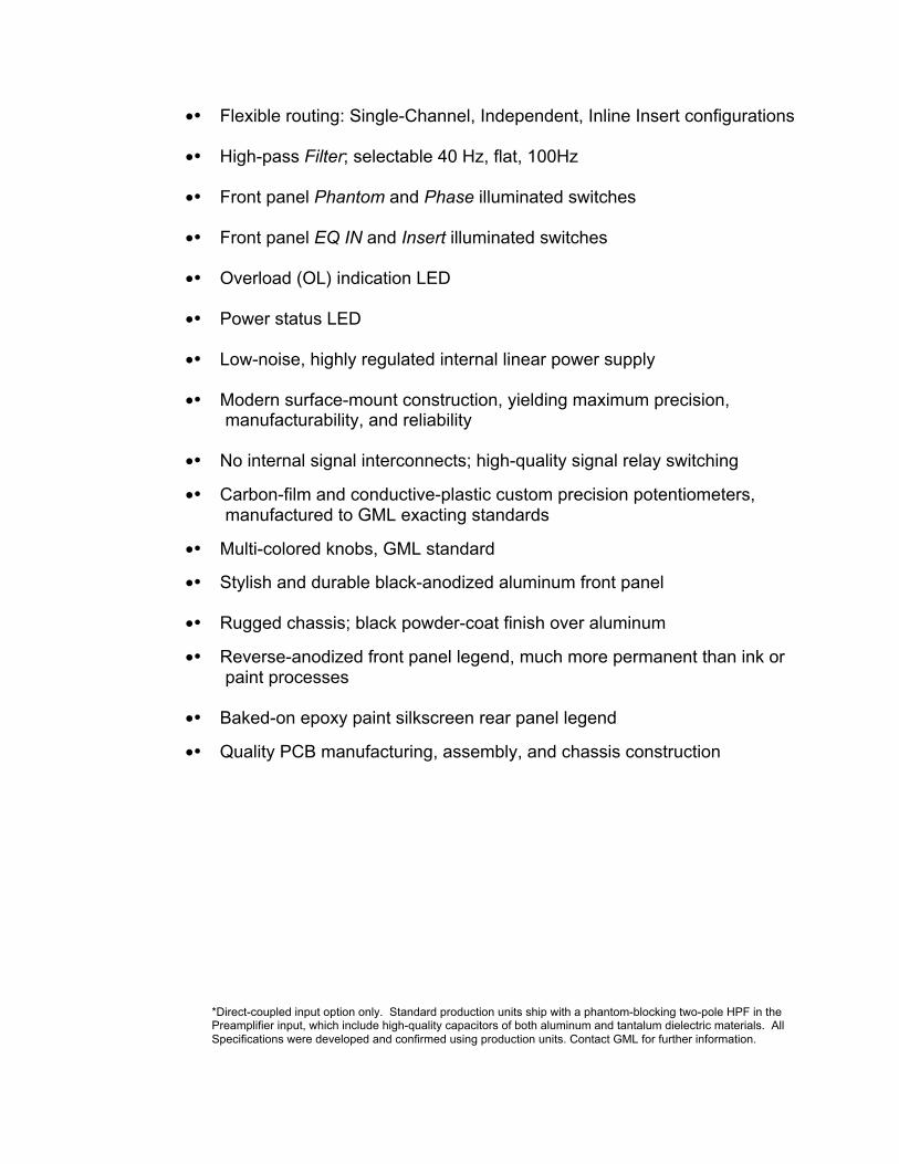
•• Flexible routing: Single-Channel, Independent, Inline Insert configurations
•• High-pass Filter; selectable 40 Hz, flat, 100Hz
•• Front panel Phantom and Phase illuminated switches
•• Front panel EQ IN and Insert illuminated switches
•• Overload (OL) indication LED
•• Power status LED
•• Low-noise, highly regulated internal linear power supply
•• Modern surface-mount construction, yielding maximum precision,manufacturability, and reliability
•• No internal signal interconnects; high-quality signal relay switching
•• Carbon-film and conductive-plastic custom precision potentiometers,manufactured to GML exacting standards
•• Multi-colored knobs, GML standard
•• Stylish and durable black-anodized aluminum front panel
•• Rugged chassis; black powder-coat finish over aluminum
•• Reverse-anodized front panel legend, much more permanent than ink orpaint processes
•• Baked-on epoxy paint silkscreen rear panel legend
•• Quality PCB manufacturing, assembly, and chassis construction
*Direct-coupled input option only. Standard production units ship with a phantom-blocking two-pole HPF in thePreamplifier input, which include high-quality capacitors of both aluminum and tantalum dielectric materials. AllSpecifications were developed and confirmed using production units. Contact GML for further information.
The Model 2032 Microphone Preamplifier / Parametric Equalizer offers exceptionalflexibility and sonic accuracy when dealing with a variety of signal sources andconditions. Allowing quick adjustment of any critical parameter, the operation of theModel 2032 remains straightforward despite an extensive feature set. Indeed, areduction in apparent complexity is achieved by taking a building-block approach tooperational analysis.
I. Preamplifier
The preamplifier section of the Model 2032 Microphone Preamplifier / ParametricEqualizer is based on the gain stage of the Model 8300 Transformerless MicrophonePreamplifier, though there are some design changes and a few additions to expand itscapabilities further than is realized in the highly specialized Model 8300 mic preamp.
Two input formats are accommodated on the Model 2032: an Input XLR connector isprovided on the back panel for microphone input, while the front panel sports a 1/4"unbalanced musical instrument connector. Input signal selection is determined by theSource toggle switch.
The microphone input of the Model 2032 is an exact copy of the Model 8300 inputcircuitry, complete with 48V phantom power and subsequent 2-pole phantom filter.Unlike the Model 8300, the phantom power switch is conveniently located on the frontpanel and is illuminated to warn the user that phantom power is ON. The MIC input isprecision electronically balanced, 1kΩ nominal input impedance, with tremendousdynamic range, remarkably low noise, fast slew rate, and wide bandwidth.
Adding to the Model 2032 input options, the front panel MI input extends the sphere ofapplication to the realm of the oft-neglected musical instrument. This high impedanceunbalanced input (1MΩ nominal) offers low noise and low distortion, plus a widedynamic range and ruler-flat extended frequency response to outclass commoninstrument inputs. Especially useful for recording bass or electric guitar, this input canalso be used for a variety of other unbalanced sources such as electronic keyboards,samplers, etc.
As previously mentioned, the input signal for the Model 2032 is selected on the Sourceswitch, located near the left corner of the front panel. Only one source may be activethrough the channel at a time; however, signals may be present at the other inputssince the source select function does not ground unused inputs (see Specifications page of
this manual for separation figures). Phantom powering may remain On, if necessary, whenswitching between input sources without damage to other input devices since thephantom supply does not reach the or MI input. It is, however, recommended that thephantom power be turned Off when not in use to preserve power supply efficiency andeliminate possible DC pops when changing input source selection.
OPERATION

A particularly wide range of gain settings (10dB through 75dB of gain) is available forboth preamplifier inputs of the Model 2032. This feature accommodates a broad arrayof input signals, from extremely "hot" microphone inputs to extremely "low" MI inputs,which are often neglected by professional peripheral audio processing devices. Indeed,the minimal 20dB of gain found in most microphone preamplifiers can be excessive incertain circumstances, and decreases the possibility of optimized gain staging. By thesame token, real-world MI signals often require more than the typical 10 dB of gaincommonly accorded them.
A combination of the rotary Gain switch and Fine potentiometer is used to control thegain setting of the preamplifier section, with the overall gain of the preamplifiercalculated by adding the two control values. The Gain switch allocates between 15dBand 70dB of gain in precise 5dB steps, using a combination of discrete resistors for theultimate in accuracy, stability, durability, and sonic integrity. Providing +/-5dB ofcontinuously variable gain, the Fine control adds elasticity to gain setting.
Incorporated into the preamplifier section, the Phase switch activates a relay just beforethe balancing circuit of the preamp. No signal is present at the front panel Phaseswitch--it is merely a relay control and LED indicator voltage. Engaging this switchreverses the phase of the input signal, akin to swapping pins 2 and 3 on the Input XLR.In the case of the MI input, the Phase function will change the absolute polarity of agiven input signal.
II. Filter
Immediately following the preamplifier section of the Model 2032 is an extremely usefuland transparent high-pass filter (HPF), which has three optional settings: 40Hz roll-off,flat response, or 100Hz roll-off. Designed for maximum clarity and musicality, thisactive second order Butterworth high-pass filter is implemented with premium-gradeSMD film capacitors, precision resistors, and a pristine GML 9202 discrete opamp.Passband response is maximally flat for both the 40Hz and 100Hz selections, while theModel 2032's ruler-flat frequency response is preserved in the "flat" setting. A second-order high-pass filter, this circuit creates a -12dB per octave roll-off below the cornerfrequency, an appropriately flexible and powerful function since many engineers use thelow-frequency band of a fully parametric equalizer--a Model 8200, for instance--in shelfmode as a high-pass filter of sorts.
The Insert Out XLR signal is taken directly from the HPF output and is always active,regardless of the Insert switch setting. As with all Model 2032 sections, this stageexhibits extremely low noise and distortion, wide bandwidth, and dynamic range, andutilizes precise DC-servo coupling.

III. Parametric Equalizer
The EQ section of the Model 2032 Microphone Preamplifier / Parametric Equalizeroffers precision and adaptability when sculpting the response of any source. Itsoperational characteristics, duplicated from the Model 8200 Parametric Equalizer, havebeen honed through many years of use in the most critical recording and mixingsituations and have proven both reliable and remarkably accommodating.
The basis of the parametric design topology, in general, specifies control over not onlygain or attenuation, but also over both frequency and “Q” factor in multiple user-definedbands. In the case of parametric equalization, “Q” is defined as the center frequency ofthe alteration (whether gain or attenuation) divided by the bandwidth of that alteration. Itfollows, then, that low values of “Q” affect a wide range of frequencies around the cut orboost, while high values of “Q” specify a narrow slope around the center frequency.
Another important aspect of true parametric equalization, as embodied in the Model2032 equalizer section, is the existence of overlapping frequency bands, which providegreat precision and flexibility.
Specifically, this parametric equalizer provides complete control over a wide frequencyrange and “Q” setting, along with 15 dB of cut or boost on four individual bands, with thefront panel controls for frequency and “Q” mounted concentrically. The addition of the“Q” characteristic empowers the user to maintain precise and musical control over thetonal attributes of the spectrally processed signal.
The availability of up to 15 dB of gain or attenuation is significant, affording the userunprecedented control from minute adjustments to dramatic alterations over completelyflexible overlapping multiple bands. Thus, it is possible to achieve almost any particular“sound” that is desired, no matter if the goal is a subtle modification or an audiblecoloration effect.
Front panel controls for the Model 2032 equalizer section include an illuminated in/outpushbutton switch plus four color-coded bands with amplitude and dual-concentricfrequency and "Q" potentiometers. The amplitude pots are continuously variablebetween +15 dB and -15 dB, with highly accurate 0 dB settings. Each band offers awide array of frequencies to select on the outer knob of the dual-concentricpotentiometer, with a good deal of overlap between bands to accommodate almost anycombination of cuts and boosts. The Low and High bands offer counter-clockwisedetents for shelving curves in addition to the variable "Q" values from 0.4 to 4 found inthe other two bands--all on the central knobs of the dual-concentric potentiometers.Frequency markings can be found along the inner, larger ring of numbers, while theouter, smaller numbers encircling the dual-concentric potentiometer denotes "Q" value.

IV. Insert
A portion of the Model 2032's allure is the flexibility accorded the user in determining thesignal routing of the preamplifier and equalizer sections. This functionality isincorporated in the front panel Insert control, an illuminated pushbutton switch thatactivates a precious-metal contact signal relay.
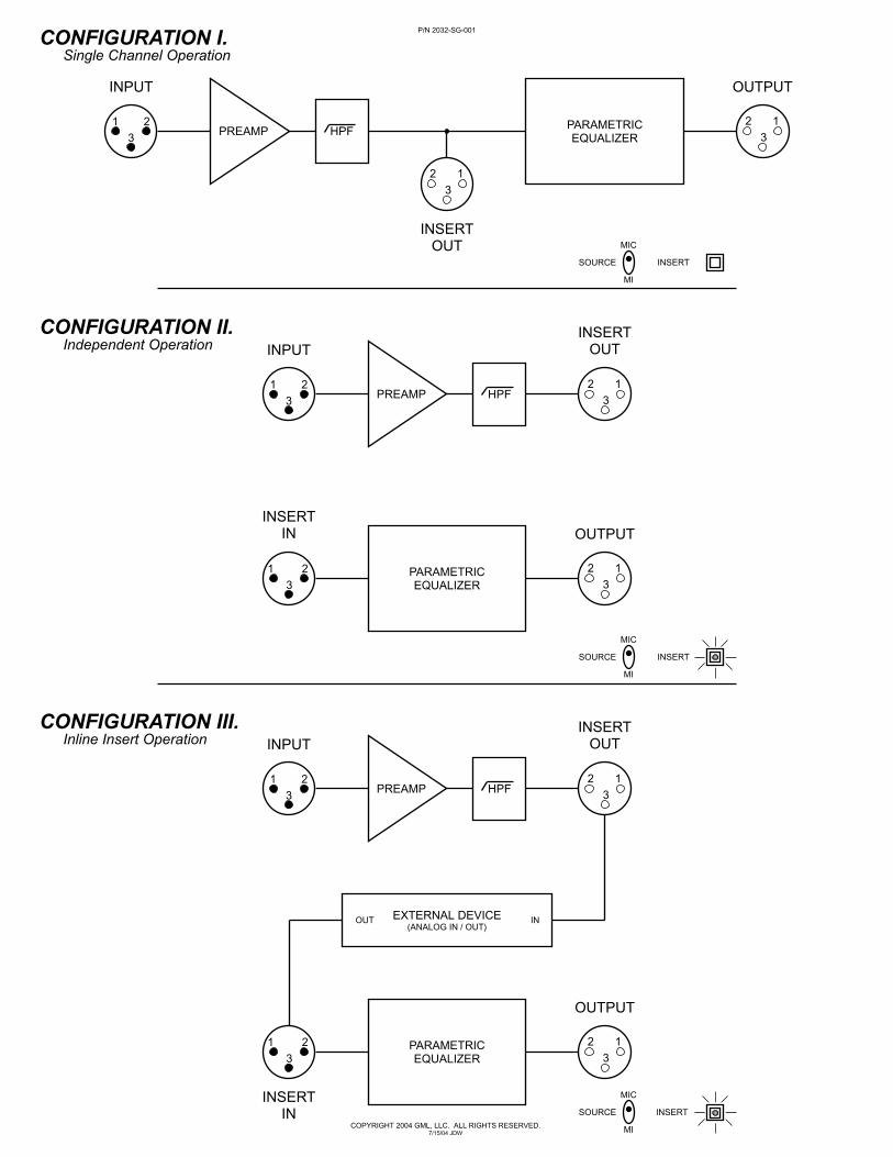
Specifically, the Insert function allows the user to configure the Model 2032 for SingleChannel, Independent, or Inline Insert operation (see Configuration illustration). SingleChannel operation feeds the preamplifier output—post-HPF—directly to the equalizerinput. Independent operation allows the preamplifier and equalizer to be used onseparate signal sources simultaneously, where the Insert Out XLR provides thepreamplifier output and the Insert In XLR sources the equalizer input signal. Essentiallya special case of the Independent configuration, Inline Insert operation places anexternal device--possibly a Model 8900 Dynamic Gain Control--between thepreamplifier and equalizer sections of the Model 2032. The external device must haveanalog input and output to interface with the analog-only architecture of the Model 2032.
In all cases, the Output XLR of the Model 2032 is the direct-coupled DC-servo correctedoutput of the equalizer stage, while the Insert Out XLR carries the direct-coupled DC-servo corrected output of the preamplifier stage, post-filter. There is, therefore, nodedicated output buffering stage; nor is there a master output level control.
Unused inputs and outputs need not necessarily be disconnected from the Model 2032when de-selected. Indeed, both outputs always transmit signal, given an appropriateinput. Neither of the XLR inputs (Input, Insert In) short to ground when not in use.Leaving a 1/4” connector in the MI jack with MIC selected will not adversely affect eitherthe Model 2032 or the external musical instrument. The MI input, however, does shortthe signal pin (tip) to ground when no connector is inserted, regardless of the position ofthe Source switch.
V. Overload (OL)
In light of the considerable amounts of gain available in both the preamplifier andequalizer sections of the Model 2032 Microphone Preamplifier / Parametric Equalizer,the OL (overload) indicator LED provides an essential metering function. This peakdetection meter monitors both the preamplifier and equalizer outputs to preemptivelywarn of possible signal overload, regardless of the configuration selected on the Insertcontrol. It should be noted that although this warning LED is triggered at 24dBu fromeither aforementioned signal, actual clipping throughout the Model 2032 is notexperienced until approximately 27.5dBu, thanks to the extended headroom of GML9202 discrete opamps.

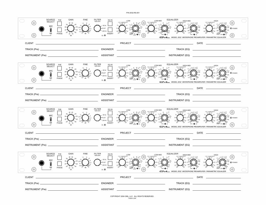
A. Source determines which input the preamplifier section utilizes, either MIC or MI.
B. P48 applies 48V Phantom power to pins 2 and 3 of the mic INPUT XLR.
C. Gain sets the coarse gain in precise 5dB steps, from 15dB to 70dB.
D. Fine provides a continuously variable amount of gain, from –5dB to +5dB.
E. Filter regulates the high-pass filter mode of operation, optionally 40Hz, flat, or 100Hz.
F. EQ IN engages the parametric equalizer. No signal is present at the switch; it merelycontrols a high quality signal relay.
G. Cut/Boost adjusts the amount of gain or attenuation for each equalizer band with aguaranteed 0dB center position.
H. Frequency (outer ring) establishes the center frequency for each equalizer band. Lowerfrequencies are counter-clockwise while higher frequencies are clockwise.
I. Q (inner knob) appoints the sharpness of a given cut/boost for each equalizer band. Widerpeaks/dips are counter-clockwise while more narrow peaks/dips are clockwise. LOW andHIGH bands provide a SHELF mode of operation at the full-CCW detent.
J. The MI input jack furnishes a convenient unbalanced high impedance input. Tip is “hot”,sleeve is common; tip is shorted to common when no plug is inserted to minimize noise.
K. Phase reverses the preamplifier input signal polarity. No signal is present at the switch; itmerely controls a high quality signal relay.
L. The overload (OL) indicator monitors both the preamplifier and equalizer outputs to warn ofpossible signal overload. This peak-responding LED is triggered at +24dBu, several dBbelow actual clipping.
M. Insert splits the equalizer input from the preamplifier output for Independent or Inline Insertconfigurations. No signal is present at the switch; it controls a high quality signal relay.
N. The POWER status LED indicates the presence of appropriate AC mains voltage at the rearpanel IEC inlet and correct internal DC supply operation.
MODEL 2032 FRONT PANEL DIAGRAM

A. City of Los Angeles, UL, and CE standards require these safety statements.“WARNING – To reduce the risk of fire or electric shock do not expose this device to rain or moisture.”
“CAUTION: Risk of electric shock. This unit contains no user-serviceable parts—do not open. Refer serviceto qualified personnel only.”
B. The Grounds terminal block gives a common point of continuity to the electronics ground (upper) andthe chassis ground (lower). Normally these terminals are tied together with the Ground Strap.
C. An IEC-type socket provides connection to AC mains power (50 / 60 Hz) via an external power cable.A 6-ft. power cable ships standard with all new units.
D. Protecting both the power supply fuse and a spare, the safety-interlocking Fuse Holder prevents fuseremoval with an IEC plug inserted. Replace with 500mA (110V) or 250mA (220V) Slo-Blow 250V-rated fuse (5mm x 20mm package). NOTICE: Repeated fuse failure may indicate internal fault.Request service as per Contacts section of this manual.
E. Allowing worldwide operation, the Voltage Select switch sets the internal power supply for the correctAC mains line voltage, either 110V or 220V. Gently rotate the switch using a small flat-headscrewdriver; the voltage setting is indicated by the small triangle. WARNING – A mismatch betweenAC line voltage and setting of the Voltage Select switch may cause permanent damage.
F. Internal supply voltage regulator mounting screws should NOT be shorted nor loosened, as this couldimpair unit performance and/or cause irreversible damage.
G. Uniquely assigned, the GML Serial Number Tag contains a permanent imprint of the serial number.
H. The Output XLR provides a professional interconnect to external devices. DC Servo corrected, directcoupled, and unbalanced (pin 2 “hot”), this yields the equalizer output.
I. Active when Insert is engaged, the Insert In XLR is a balanced feed to the equalizer input.
J. Regardless of Insert status, Insert Out monitors the preamp output, post-filter. This XLR is DC Servocorrected, direct coupled, and unbalanced (pin 2 “hot”).
K. The Input XLR applies signal to the preamplifier when MIC is selected on the Source switch.
L. CE (European Electromagnetic Compatibility) marking indicates full compliance with EN 55013:1990(Electromagnetic Disturbance, Sects. 3.2, 3.5) and EN 55020:1988 (Electromagnetic Compatibility,Sects. 4.3, 5.4, 6.2, 7.0, 8.0).
M. The Ground Strap normally connects electronics ground and chassis ground; however, in certainsituations it may be advantageous and/or necessary to keep these ground references independent (toeliminate ground loops in some installations, for instance).
N. An Output Warning notice reminds users of the inherent danger and permanent damage associatedwith shorting the output. Normally, pin 2 is wired as the “hot” output pin.
MODEL 2032 BACK PANEL DIAGRAM
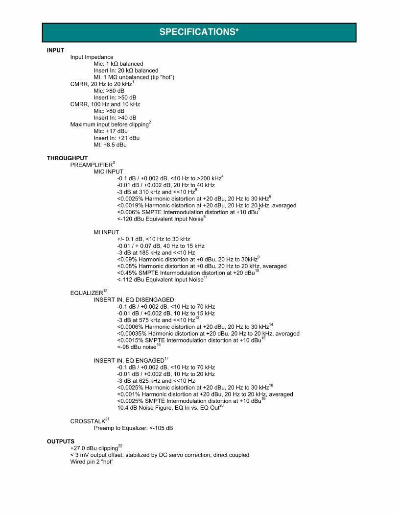
INPUTInput Impedance
Mic: 1 kΩ balancedInsert In: 20 kΩ balancedMI: 1 MΩ unbalanced (tip "hot")
CMRR, 20 Hz to 20 kHz1
Mic: >80 dBInsert In: >50 dB
CMRR, 100 Hz and 10 kHzMic: >80 dBInsert In: >40 dB
Maximum input before clipping2
Mic: +17 dBuInsert In: +21 dBuMI: +8.5 dBu
THROUGHPUTPREAMPLIFIER3
MIC INPUT-0.1 dB / +0.002 dB, <10 Hz to >200 kHz4
-0.01 dB / +0.002 dB, 20 Hz to 40 kHz-3 dB at 310 kHz and <<10 Hz5
<0.0025% Harmonic distortion at +20 dBu, 20 Hz to 30 kHz6
<0.0019% Harmonic distortion at +20 dBu, 20 Hz to 20 kHz, averaged<0.006% SMPTE Intermodulation distortion at +10 dBu7
<-120 dBu Equivalent Input Noise8
MI INPUT+/- 0.1 dB, <10 Hz to 30 kHz-0.01 / + 0.07 dB, 40 Hz to 15 kHz-3 dB at 185 kHz and <<10 Hz<0.09% Harmonic distortion at +0 dBu, 20 Hz to 30kHz9
<0.08% Harmonic distortion at +0 dBu, 20 Hz to 20 kHz, averaged<0.45% SMPTE Intermodulation distortion at +20 dBu10
<-112 dBu Equivalent Input Noise11
EQUALIZER12
INSERT IN, EQ DISENGAGED-0.1 dB / +0.002 dB, <10 Hz to 70 kHz-0.01 dB / +0.002 dB, 10 Hz to 15 kHz-3 dB at 575 kHz and <<10 Hz13
<0.0006% Harmonic distortion at +20 dBu, 20 Hz to 30 kHz14
<0.00035% Harmonic distortion at +20 dBu, 20 Hz to 20 kHz, averaged<0.0015% SMPTE Intermodulation distortion at +10 dBu15
<-98 dBu noise16
INSERT IN, EQ ENGAGED17
-0.1 dB / +0.002 dB, <10 Hz to 70 kHz-0.01 dB / +0.002 dB, 10 Hz to 20 kHz-3 dB at 625 kHz and <<10 Hz<0.0025% Harmonic distortion at +20 dBu, 20 Hz to 30 kHz18
<0.001% Harmonic distortion at +20 dBu, 20 Hz to 20 kHz, averaged<0.0025% SMPTE Intermodulation distortion at +10 dBu19
10.4 dB Noise Figure, EQ In vs. EQ Out20
CROSSTALK21
Preamp to Equalizer: <-105 dB
OUTPUTS+27.0 dBu clipping22
< 3 mV output offset, stabilized by DC servo correction, direct coupledWired pin 2 "hot"
SPECIFICATIONS*
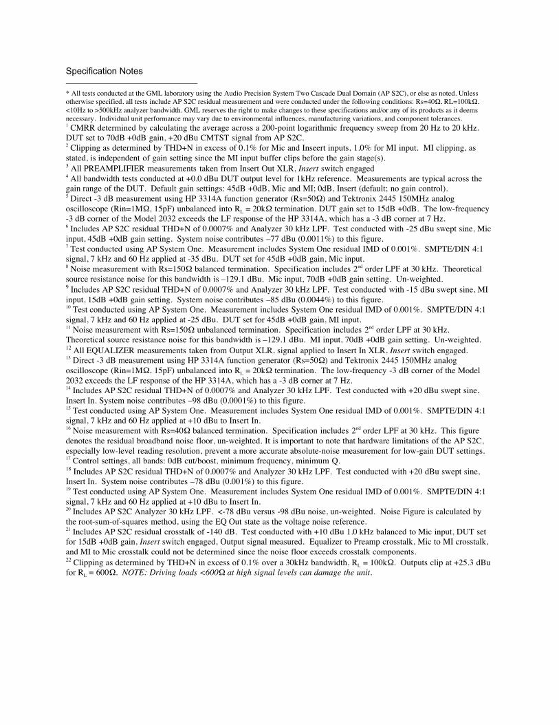
Specification Notes * All tests conducted at the GML laboratory using the Audio Precision System Two Cascade Dual Domain (AP S2C), or else as noted. Unlessotherwise specified, all tests include AP S2C residual measurement and were conducted under the following conditions: Rs=40Ω, RL=100kΩ,<10Hz to >500kHz analyzer bandwidth. GML reserves the right to make changes to these specifications and/or any of its products as it deemsnecessary. Individual unit performance may vary due to environmental influences, manufacturing variations, and component tolerances.1 CMRR determined by calculating the average across a 200-point logarithmic frequency sweep from 20 Hz to 20 kHz.DUT set to 70dB +0dB gain, +20 dBu CMTST signal from AP S2C.2 Clipping as determined by THD+N in excess of 0.1% for Mic and Inseert inputs, 1.0% for MI input. MI clipping, asstated, is independent of gain setting since the MI input buffer clips before the gain stage(s).3 All PREAMPLIFIER measurements taken from Insert Out XLR, Insert switch engaged4 All bandwidth tests conducted at +0.0 dBu DUT output level for 1kHz reference. Measurements are typical across thegain range of the DUT. Default gain settings: 45dB +0dB, Mic and MI; 0dB, Insert (default; no gain control).5 Direct -3 dB measurement using HP 3314A function generator (Rs=50Ω) and Tektronix 2445 150MHz analogoscilloscope (Rin=1MΩ, 15pF) unbalanced into RL = 20kΩ termination. DUT gain set to 15dB +0dB. The low-frequency-3 dB corner of the Model 2032 exceeds the LF response of the HP 3314A, which has a -3 dB corner at 7 Hz.6 Includes AP S2C residual THD+N of 0.0007% and Analyzer 30 kHz LPF. Test conducted with -25 dBu swept sine, Micinput, 45dB +0dB gain setting. System noise contributes –77 dBu (0.0011%) to this figure.7 Test conducted using AP System One. Measurement includes System One residual IMD of 0.001%. SMPTE/DIN 4:1signal, 7 kHz and 60 Hz applied at -35 dBu. DUT set for 45dB +0dB gain, Mic input.8 Noise measurement with Rs=150Ω balanced termination. Specification includes 2nd order LPF at 30 kHz. Theoreticalsource resistance noise for this bandwidth is –129.1 dBu. Mic input, 70dB +0dB gain setting. Un-weighted.9 Includes AP S2C residual THD+N of 0.0007% and Analyzer 30 kHz LPF. Test conducted with -15 dBu swept sine, MIinput, 15dB +0dB gain setting. System noise contributes –85 dBu (0.0044%) to this figure.10 Test conducted using AP System One. Measurement includes System One residual IMD of 0.001%. SMPTE/DIN 4:1signal, 7 kHz and 60 Hz applied at -25 dBu. DUT set for 45dB +0dB gain, MI input.11 Noise measurement with Rs=150Ω unbalanced termination. Specification includes 2nd order LPF at 30 kHz.Theoretical source resistance noise for this bandwidth is –129.1 dBu. MI input, 70dB +0dB gain setting. Un-weighted.12 All EQUALIZER measurements taken from Output XLR, signal applied to Insert In XLR, Insert switch engaged.13 Direct -3 dB measurement using HP 3314A function generator (Rs=50Ω) and Tektronix 2445 150MHz analogoscilloscope (Rin=1MΩ, 15pF) unbalanced into RL = 20kΩ termination. The low-frequency -3 dB corner of the Model2032 exceeds the LF response of the HP 3314A, which has a -3 dB corner at 7 Hz.14 Includes AP S2C residual THD+N of 0.0007% and Analyzer 30 kHz LPF. Test conducted with +20 dBu swept sine,Insert In. System noise contributes –98 dBu (0.0001%) to this figure.15 Test conducted using AP System One. Measurement includes System One residual IMD of 0.001%. SMPTE/DIN 4:1signal, 7 kHz and 60 Hz applied at +10 dBu to Insert In.16 Noise measurement with Rs=40Ω balanced termination. Specification includes 2nd order LPF at 30 kHz. This figuredenotes the residual broadband noise floor, un-weighted. It is important to note that hardware limitations of the AP S2C,especially low-level reading resolution, prevent a more accurate absolute-noise measurement for low-gain DUT settings.17 Control settings, all bands: 0dB cut/boost, minimum frequency, minimum Q.18 Includes AP S2C residual THD+N of 0.0007% and Analyzer 30 kHz LPF. Test conducted with +20 dBu swept sine,Insert In. System noise contributes –78 dBu (0.001%) to this figure.19 Test conducted using AP System One. Measurement includes System One residual IMD of 0.001%. SMPTE/DIN 4:1signal, 7 kHz and 60 Hz applied at +10 dBu to Insert In.20 Includes AP S2C Analyzer 30 kHz LPF. <-78 dBu versus -98 dBu noise, un-weighted. Noise Figure is calculated bythe root-sum-of-squares method, using the EQ Out state as the voltage noise reference.21 Includes AP S2C residual crosstalk of -140 dB. Test conducted with +10 dBu 1.0 kHz balanced to Mic input, DUT setfor 15dB +0dB gain, Insert switch engaged, Output signal measured. Equalizer to Preamp crosstalk, Mic to MI crosstalk,and MI to Mic crosstalk could not be determined since the noise floor exceeds crosstalk components.22 Clipping as determined by THD+N in excess of 0.1% over a 30kHz bandwidth, RL = 100kΩ. Outputs clip at +25.3 dBufor RL = 600Ω. NOTE: Driving loads <600Ω at high signal levels can damage the unit.

One channel, multi-input, gain, filter, parametric equalizer with insert capabilityPreamplifier section
Two inputs: MIC (balanced, XLR), MI (unbalanced, 1/4”; Tip = Signal, Sleeve = Ground)Input Source control: MIC or MIGain control: 10dB to 70dB, 5dB stepsFine control: -5dB to +5dB, continuously variablePhase switch, illuminated pushbutton: in-phase (LED off), phase reverse (LED on)P48 switch, illuminated pushbutton: phantom on (LED on), phantom off (LED off)
Filter -- Second-order Butterworth active high-pass filter; 100Hz, flat, 40Hz
Equalizer sectionEQ IN switch, illuminated pushbutton: equalizer in (LED on), equalizer out (LED off)Four bands, fully parametric, continuously variable
1. 15 Hz – 800 Hz, Q of 0.4 – 4.0 or shelving, 15 dB boost/cut2. 120 Hz – 8 kHz, Q of 0.4 – 4.0, 15 dB boost/cut3. 400 Hz – 26 kHz, Q of 0.4 – 4.0, 15 dB boost/cut4. 400 Hz – 26 kHz, Q of 0.4 – 4.0 or shelving, 15 dB boost/cut
Insert switch, illuminated pushbutton: engaged (LED on), disengaged (LED off)Configurations
1. Single Channel – preamplifier output feeds equalizer input2. Independent – split operation3. Inline Insert – external device inserted between preamplifier and equalizer
MI (1/4” phone) – 1 MΩ unbalanced, buffered preamplifier input with MI selected on Source
Input (XLR)1 kΩ balanced bridging, transformerless; microphone inputPreamplifier input with MIC selected on Source switch
Insert Out (XLR)Direct-coupled, DC-servo corrected, unbalanced (pin2=Sig, pins1,3=Gnd)Preamplifier and Filter output
Insert In (XLR)20 kΩ balanced bridging, transformerless; line inputEqualizer input with Insert engaged
Output (XLR)Direct-coupled, DC-servo corrected, unbalanced (pin2=Sig, pins1,3=Gnd)Equalizer output
OL -- Red LED, +24dBu peak indication: monitors preamplifier and equalizer outputs
POWERInternal linear power supply; +/-28 VDC, +/-18 VDC, +48 VDCAC line (IEC): 110V/220V select, 50Hz/60HzApprox. power consumption: 28W; 500mA/250V slo-blo fuse installed (110V operation)Separate Ground and Chassis connections at rearBlue power indication LED
MECHANICAL19" W x 1.75" H x 10" D rack mount chassis, black anodized aluminum, silver legendWeight: 11 lbs., approximate; shipping weight may vary
FORM FACTOR

On the surface it is not eminently evident just how much "new" design is represented inthe Model 2032 Microphone Preamplifier / Parametric Equalizer. Indeed, the equalizersection has been barely modified from the reference-standard Model 8200 ParametricEqualizer, while the Model 8300 Transformerless Microphone Preamplifier is largelycopied in the preamplifier section. The design innovation, however, of the Model 2032lies, at least partially, in the confluence of these diverse parts into a cohesive andextremely precise whole.
The most notable and noticeable addition to the aforementioned GML legacy productsembodied in the Model 2032 is the inclusion of an internal power supply--a first for GML.While the absolute lowest noise performance can best be achieved with an externalpower supply, this completely original design minimizes the compromises in order toyield the savings in space and cost that can derive from an internal supply topology.
The inclusion of multiple inputs certainly adds to the allure of the Model 2032, where theMI input circuitry represents a welcome addition to the standard microphone input. TheInput XLR can even accommodate low-level “line” sources needing 10dB of gain ormore, assuming the external device’s output can drive the 1kΩ load impedance. Thus,the Model 2032 preamplifier can capably handle a wide array of input sources.
Much akin to the input section of the Model 2020, the preamplifier section of the Model2032 builds upon and expands the capabilities of the Model 8300. The inclusion of apolarity inversion function (Phase) and front-panel phantom switching (P48) certainlybolster user-friendliness. Similarly, the Fine control adds flexibility by ensuring theability to find optimum gain staging between 5dB steps, while also allowing instant gainadjustment with near-infinite resolution.
The Insert function of the Model 2032 complements the various processing blocks,providing a great deal of versatility. With the press of this button, the preamplifier andequalizer can be split apart for either completely independent operation or for insertionof an external device between them. The front panel capacity to switch between inputsalso augments the agility inherent in the Model 2032.
Though the front panel equalizer controls seem very intuitive to the initiated andexperienced audio engineer, the circuit design behind these controls is anything butsimple and straightforward. The Model 2032 equalizer section features an exemplarybalancing circuit in addition to the actual equalization circuits. It is important to keep inmind that all circuits in any device necessarily alter the sonic character of any complexsignal, though these colorations have been meticulously minimized in the design of theModel 2032. Therefore, no alteration is required to compensate for the spectralsignature induced by the unit itself.
Great care has also been taken--as in all aspects of the GML Model 2032--to select thehighest quality components, from the potentiometers on the front panel to the smallest
DESIGN

passive elements. This attention to detail partially elucidates the quality found in theMicrophone Preamplifier / Parametric Equalizer. These component choices, coupledwith superior design techniques and a proclivity towards innovation, combine to makethe Model 2032 a most powerful, flexible, and transparent single channel processor.
Another feature that distinguishes the Model 2032 is its inherent dynamic range.Naturally, this means that the preamplifier and filter sections maintain low-noise, high-headroom, transparent operation under all signal conditions, at any control setting. Inthe equalizer section, this extended dynamic range allows for the addition of 15 dB ofgain in multiple frequency bands simultaneously without even a hint of distortion or lossof detail and authority. This amazing accuracy is due in large part to the GMLpropensity to design all audio circuits from discrete components. Discrete designs,when executed properly, help to preserve not only sonic integrity and musicality, butalso to maintain the widest dynamic range through the entire signal path, thuseliminating many sonic compromises and limitations. Not only do these discretetopologies--and the GML 9202 discrete opamp in particular--sound better than theirintegrated counterparts, they also offer the ability to design for higher signal levelsinternally, while also optimizing dynamic range by providing a low noise floor.
An additional benefit of the discrete circuit topology used in the Model 2032 is increasedbandwidth. Not only does this significant extension--of both high and low frequencies--provide for more detail and realism; it also ensures a greater degree of linearity in thetraditional audio spectrum (20 Hz to 20 kHz) by locating bandwidth poles supercedingthese commonly-accepted limits. Indeed, the frequency response of the Model 2032 iswell within +/- 0.1 dB from below 10 Hz to well above 80 kHz, while the +/- 3.0 dBresponse exceeds the ability of most audio test apparatus to measure.
Compactness of design affords the Model 2032 distinct advantages, both from a designstandpoint and a user perspective. Originally conceived as a project to provide GMLprocessing in an eminently portable form factor for remote recording and non-fixedinstallations, the Model 2032 bundles a no-compromise preamplifier, filter, andparametric equalizer into a single rack space chassis. Packing an internal powersupply--thus obviating the need to transport bulky external supplies--adds to theportability, making it no hassle to setup a rack full of 2032’s. From a design viewpoint,locating all processing blocks on one motherboard and taking full advantage of surface-mount technology yields superior reliability and uniformity, while controlling expenses.All internal signal interconnects are eliminated, leaving only hard-wired audio in/outconnectors and high-quality relays in the signal path. No hand wiring of audio signalpaths is required, thus further reducing cost and improving reliability.
Integral to the superb quality of all GML products is the power supply, an internal powersupply in this case. No piece of electronic equipment can operate as designed withoutan adequate power supply; however, many contemporary processors do not feature asupply that can provide clean, quiet power without unduly heating the device. TheModel 2032 internal supply excels in this respect, maintaining the ability to deftly reactto highly transient signal content and extreme circuit actions. While the absolute lowestnoise performance can best be achieved with an external power supply, this highlyregulated low-noise linear design minimizes the compromises in order to yield thesavings in space and cost that can derive from an internal supply topology. Utilizing acustom toroidal power transformer and precision regulators in a new design withmeticulous layout, the net difference in preamplifier noise is approximately 1dB, whileno increase in noise for the filter or equalizer is discernable. The internal powerdistribution scheme employed by the Model 2032 is also responsible for preserving thehighest audio quality throughout the many circuits of the Microphone Preamplifier /Parametric Equalizer.
Please note: The Model 2032 does not include a power On/Off switch; the unit is “on” when AC linevoltage is applied to the rear panel IEC socket. Ensure proper IEC inlet settings (110V / 220V) beforeapplying power to prevent damage.
It is important to keep in mind that the noise performance of the Model 2032 varies withoperational settings. An increase in noise is to be expected when switching from the'EQ Out' state to the 'EQ In' state. The reason for this characteristic is inherent toGML’s proprietary design, which places the control before all of the processing bands.This gives GML parametric equalizers two distinct advantages: first, potentiometer noiseis attenuated; second, the likelihood of internal overload is extremely remote, if notimpossible, even with 15 dB of gain available in each band. Notably, the mostdangerous condition for internal overload is experienced when using just a bit of EQwith very high-level input signals. The big difference between GML units and non-GMLunits comes not only in design topology, but also in component choices. In fact, theGML parametric topology is not really feasible with IC op-amps--they're always noisierthan discretes--and only works with quiet, transparent discrete op-amps such as theGML 9202, which can cleanly handle output signals up to +27.5dBu. One shouldexpect the noise floor to increase proportionally with gain, frequency, and "Q", inaccordance with the laws of physics.
POWER SUPPLY
A NOTE REGARDING NOISE

Note: This unit is a highly sensitive device that includes many complex circuits. THIS UNIT CONTAINS NO USER-SERVICEABLE PARTS.
Warning: Risk of electric shock if top cover is removed.
In the event of unit operational failure, contact GML Service and Technical Support.Refer to the "Contacts" page of this manual, or for more current contact information,check the web site. Please be prepared to describe in detail the exact problem that theunit is experiencing, including: failure conditions, system signal flow, exact failuremanifestation, events and actions leading to the failure, etc. Also, be able to quicklyprovide contact information and the unit's GML Serial Number.
It is highly recommended that customers do not attempt to troubleshoot their own unitsor have them serviced at unauthorized repair centers. Opening the case of the unit willbreak several manufacturing seals and void the GML warranty--these securitymeasures cannot be readily detected nor easily thwarted, and should be respectedwholeheartedly. These measures also act to protect GML intellectual property so thatGML may continue to design high-end professional audio peripherals.
The following list of notices will help ensure the longevity of the Model 2032.
• Allow 15-20 minutes for DC servo settling after power-on. Operating the unit before the servossettle may cause clicks and pops that can potentially damage speakers and/or other devices.
• The outputs of this unit are DC Servo stabilized, direct coupled, unbalanced and wired pin 2 “hot”.Shorting either output (Insert Send, Output) will cause permanent damage.
• This unit contains ESD-sensitive components; handle with care.
• Provide adequate ventilation for the Model 2032. Inordinate heat buildup can cause prematureaging of the components in the unit and may lead to operational failures.
• This unit contains no user-serviceable parts: refer service to GML Service only.
• The availability of extraordinary amounts of gain throughout the Model 2032 necessitates carefulattention to the OL meter to avoid internal overload and subsequent sonic degradation.
• To avoid potentially large DC pops, switch inputs or Phantom power at minimal Gain settings.
• It is recommended that the Model 2032 be left powered-on for fixed installations. Frequent and/orexcessive power cycling may shorten the life of this unit.
• Front panel legend markings reflect approximate values, which may vary from unit to unit due tocomponent tolerances, environmental conditions, normal aging, etc. Frequency, gain, and Qaccuracy are not specified nor guaranteed for the Model 2032.
TROUBLESHOOTING
NOTICES

General Information:GML, LLC.615.790.1016 (ph)615.794.4802 (fax)www.massenburg.com
Service and Technical Support:GML, LLC.Franklin, TN615.790.9946 (ph)www.massenburg.com
Engineering:GML, LLC.Attn: Jeffrey Warren, Chief EngineerFranklin, TN615.790.9946 (ph)email: [email protected]
Pricing/Ordering:USA Sales Office:TransAmerica Audio GroupLas Vegas, NV702.365.5155 (ph)[email protected]
Japan Sales Office:ProMedia AudioTokyo, Japan+813-3-5397-7092 (ph)[email protected]
European Distribution:BEE DistributionGenval, Belgium+32-2-653-90-77 (ph)[email protected]
ORContact your local dealer--visit our online dealer locator at www.massenburg.com
CONTACTS

All designs, circuit board artwork, front panel artwork, text contained herein and therein,and all other intellectual material is the sole property of George Massenburg Labs, LLC(and/or GML, Inc.). Unauthorized use, distribution, reproduction, etc. is strictlyprohibited. GML intellectual property is protected by U.S. and international copyrightlaws. Violators will be prosecuted to the fullest extent of all applicable laws.
Transfer of ownership of this unit neither confers nor implies any transfer of ownershipof the intellectual property, proprietary design, etc. contained herein.
THIS PAGE IS ONLY A REFERENCE AT THIS TIME. A FINAL REVISIONCONTAINING ALL PERTINENT INFORMATION WILL BE INCLUDED IN FUTURERELEASES OF THIS DOCUMENT.
CreditsConcept: George Massenburg and Jeffrey Warren
Written by: Jeffrey WarrenDiagrams: Jeffrey Warren
Edited by: Jeffrey Warren and George MassenburgAdditional editing: David Robinson, Frank Wire
Technical assistance: Frank Wire, Manny Sanchez, Michael Wilk
NOTICE OF COPYRIGHT AND OWNERSHIP

Model 2020 High Resolution Discrete Input Channel
Model 2030 Mastering Dynamic Gain Control, Series III
Model 8200 Parametric Equalizer, Series II
Model 8300 Transformerless Microphone Preamplifier
Model 8355 Power Supply
Model 8900 Dynamic Gain Control, Series III
Model 9015 Power Supply
Model 9500 Two Channel 5-Band Parametric Mastering Equalizer
HRT 9100 Mixer
HRT 9145 Multi-Output Power Supply
Model 9550 Two Channel Digital Noise Filter
Model 9560 Digital Noise Filter w/ Macintosh Controller
For ordering information, contact:
USA Sales Office:TransAmerica Audio GroupLas Vegas, NV702.365.5155 (ph)[email protected]
Japan Sales Office:ProMedia AudioTokyo, Japan+813-3-5397-7092 (ph)[email protected]
European Distribution:BEE DistributionGenval, Belgium+32-2-653-90-77 (ph)[email protected]
ORContact your local dealer--visit our online dealer locator at www.massenburg.com
ADDITIONAL GML PERIPHERALS
1 2
3
2 1
3
2 1
3
PREAMP PARAMETRICEQUALIZER
HPF
INPUT
INSERTOUT
OUTPUT
1 2
3
2 1
3PREAMP HPF
INPUT
PARAMETRICEQUALIZER
INSERTOUT
OUTPUT
1 2
3
INSERTIN
1 2
3
2 1
3PREAMP HPF
INPUT
PARAMETRICEQUALIZER
INSERTOUT
OUTPUT
1 2
3
INSERTIN
EXTERNAL DEVICE(ANALOG IN / OUT)
INOUT
COPYRIGHT 2004 GML, LLC. ALL RIGHTS RESERVED.7/15/04 JDW
P/N 2032-SG-001
2 1
3
2 1
3
CONFIGURATION II.
CONFIGURATION III.
CONFIGURATION I.Single Channel Operation
Independent Operation
Inline Insert Operation
MIC
MI
INSERTSOURCE
MIC
MI
INSERTSOURCE
MIC
MI
INSERTSOURCE

1 2
3MIC
2 1
3
OUTPUT
MI(musical
instrument)
MODEL 2032 MICROPHONE PREAMPLIFIER / PARAMETRIC EQUALIZERBLOCK DIAGRAMAll Routing Options
SOURCE
S1.A
S1.B
INPUTGAIN +BALANCING
P48
S2
PHASE
S3
+5dB
-5dB
FINE
CW
70dB
15dB
GAIN
CW
HPF(2nd order Butterworth)
40Hz100Hz
FLAT
S5
S4
CW2
13
1 2
3
INSERT
S7.A
S7.B
PARAMETRICEQUALIZER
INSERTOUT
INSERTIN
EQBANDS
(4X)
EQ IN
S6
OLmeter
INPUT1
INPUT2
1 2
3MIC
2 1
3
OUTPUT
MI(musical
instrument)
MODEL 2032 MICROPHONE PREAMPLIFIER / PARAMETRIC EQUALIZERBLOCK DIAGRAM
Independent Operation
SOURCE
S1.A
S1.B
INPUTGAIN +BALANCING
P48
S2
PHASE
S3
+5dB
-5dB
FINE
CW
70dB
15dB
GAIN
CW
HPF(2nd order Butterworth)
40Hz100Hz
FLAT
S5
S4
CW2
13
1 2
3
INSERT
S7.A
S7.B
PARAMETRICEQUALIZER
INSERTOUT
INSERTIN
EQBANDS
(4X)
EQ IN
S6
OLmeter
INPUT1
INPUT2
(Pre output)
(EQ input)
(EQ output)
COPYRIGHT 2004 GML, LLC. ALL RIGHTS RESERVED.7/13/04 JDW
P/N 2032-BD-001
CLIENT PROJECT
TRACK (Pre)
INSTRUMENT (Pre)
TRACK (EQ)
INSTRUMENT (EQ)
ENGINEER
DATE
ASSISTANT
CLIENT PROJECT
TRACK (Pre)
INSTRUMENT (Pre)
TRACK (EQ)
INSTRUMENT (EQ)
ENGINEER
DATE
ASSISTANT
CLIENT PROJECT
TRACK (Pre)
INSTRUMENT (Pre)
TRACK (EQ)
INSTRUMENT (EQ)
ENGINEER
DATE
ASSISTANT
CLIENT PROJECT
TRACK (Pre)
INSTRUMENT (Pre)
TRACK (EQ)
INSTRUMENT (EQ)
ENGINEER
DATE
ASSISTANT
COPYRIGHT 2004 GML, LLC. ALL RIGHTS RESERVED.7/09/04 JDW
P/N 2032-RS-001
8
6
4
2
.5.3
.2
.15
.14
31
0.4
1
25
16
10
43
71
.8.6
.45
.4 4
3
2.5
1.5
1
0.4
2
6
34
2
.8.5.3
.2
.14 4
3
2.5
1.5
0.4
SHELF
1
SHELF1520
25
30
3540 45
50
55
60
6570
dB
FINEGAIN
40 Hz
FLAT
100 Hz
FILTERhigh-pass
Hzx100 Q kHz Q
LOW-MID HIGH-MID HIGHLOW EQUALIZERSOURCESELECT
MI
MIC
P48
PHASE INSERT
EQ IN
MODEL 2032 MICROPHONE PREAMPLIFIER / PARAMETRIC EQUALIZER
12
9
6
30 dB
3
6
9
12-4
5
-20
dB
-3
-5
-1
34 12
9
6
33
6
9
12 12
9
6
33
6
9
121515
12
9
6
3
6
9
12
POWER
-4.5
2
1-3.5
kHz Q kHz Q1515 1515 1515
2.5
1.5
3
.15
1.5
16
10
43
71
.8.6
.45
.4 4
3
2.5
1.5
1
0.4
21.5
1
4 258
OL
CUT BOOST0 dBCUT BOOST3
0 dBCUT BOOST 0 dBCUT BOOST