Global Design Effort1 September 20-22, 2006 MAC Review LLRF for ILC S. Simrock, B. Chase GDE.
48
Global Design Effort 1 September 20-22, 2 006 MAC Review LLRF for ILC S. Simrock, B. Chase GDE
-
Upload
richard-carson -
Category
Documents
-
view
220 -
download
0
Transcript of Global Design Effort1 September 20-22, 2006 MAC Review LLRF for ILC S. Simrock, B. Chase GDE.
Global Design Effort 1September 20-22, 2006 MAC Review
LLRF for ILC
S. Simrock, B. Chase
GDE

September 20-22, 2006 MAC Review Global Design Effort 2
Requirements for ILC
• CM energy: 500 GeV. Range 200 - 500 MeV. Upgradeability to 800 GeV
• Luminosity and reliability of the machine should allow Leq = 500 fb-1 four years
• Energy scans between 200 GeV and 500 GeV. Energy change should take less than 10% of data taking time.
• Beam energy stability and precision should be below the tenth of percent level
September 20-22, 2006 MAC Review Global Design Effort 3
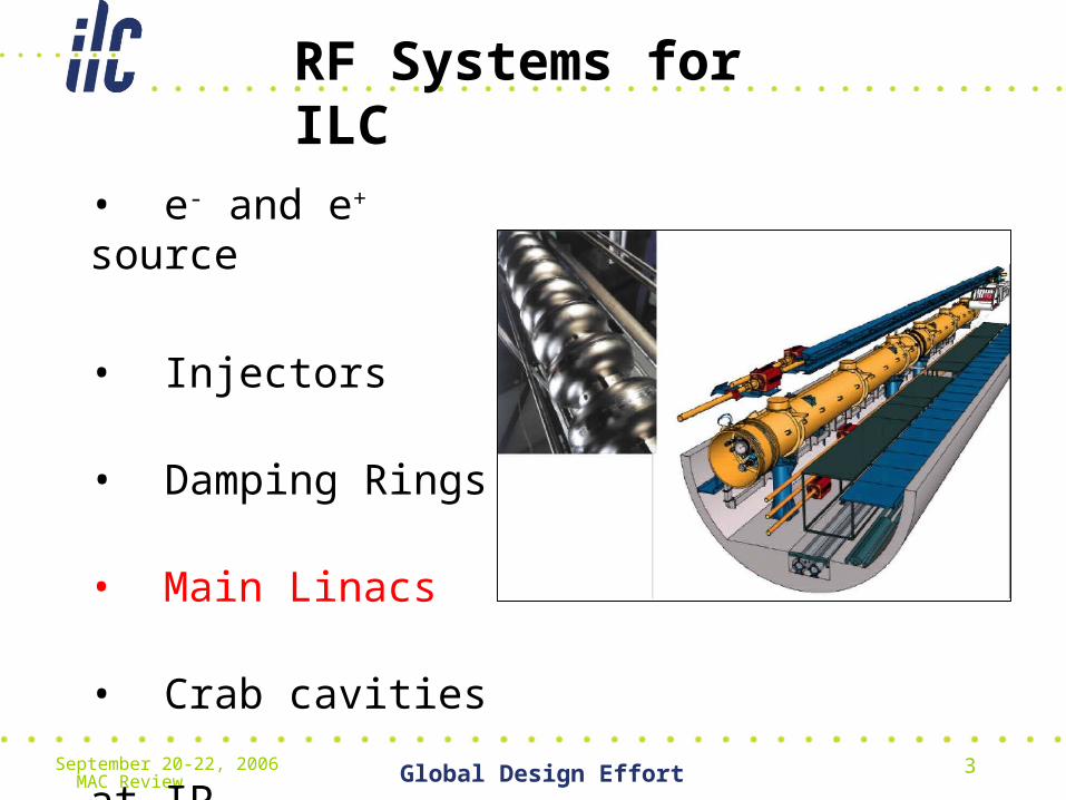
RF Systems for ILC
• e- and e+ source
• Injectors
• Damping Rings
• Main Linacs
• Crab cavities at IP
September 20-22, 2006 MAC Review Global Design Effort 4
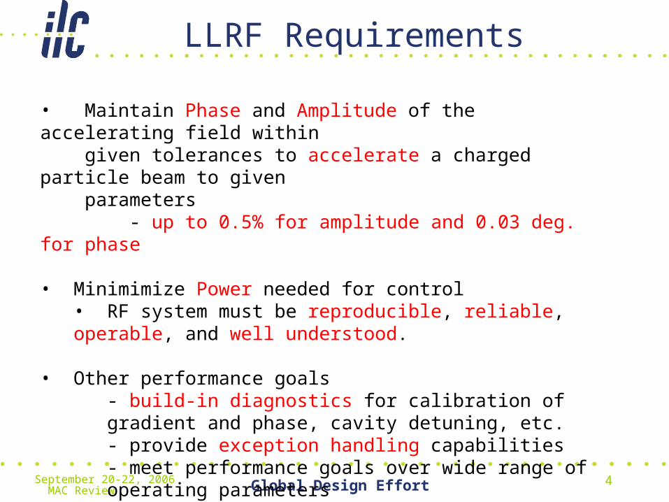
LLRF Requirements
• Maintain Phase and Amplitude of the accelerating field within given tolerances to accelerate a charged particle beam to given parameters - up to 0.5% for amplitude and 0.03 deg. for phase
• Minimimize Power needed for control• RF system must be reproducible, reliable, operable, and well understood.
• Other performance goals- build-in diagnostics for calibration of gradient and phase, cavity detuning, etc.- provide exception handling capabilities- meet performance goals over wide range of operating parameters

September 20-22, 2006 MAC Review Global Design Effort 5
Amplitude and Phase Stability
• Specification for LLRF Stability derived from Beam properties
• Energy spread (intra-bunch, bunch-to bunch, long-term)• Intra-bunch 5e-4 => desired bunch-to-bunch same order
(5e-4) to limit chromatic effects ( => emittance growth)• Long term (usually time scale for thermal drift => beam
based feedback• Emittance ( can increase as result of chromatic effects)• Arrival time jitter (will reduce luminosity)

September 20-22, 2006 MAC Review Global Design Effort 6
Requirements for Main Linacphase tolerance
limiting luminosity loss
(deg)
phase tol. limiting incr.
in energy spread (deg)
amplitude tolerance limiting
luminosity loss (%)
amplitude tolerance limiting increase in energy spread (%)
correlated BC phase errors .24 .35
uncorrelated BC phase errors .48 .59
correlated BC amplitude errors 0.5 1.8
uncorrelated BC amplitude errors
1.6 2.8
correlated linac phase errors large .36
uncorrelated linac phase errors large 5.6
correlated linac amplitude errors
large .07
Uncorr. linac amplitude errors large 1.05
Summary of tolerances for phase and amplitude control. These tolerances limit the average luminosity loss to <2% and limit the increase in RMS center-of-mass energy spread to <10% of the nominal energy spread.
Ref. Mike Church

September 20-22, 2006 MAC Review Global Design Effort 7
Requirements for Crab Cavitytiming tolerance
limitingluminosity loss to < 2%
(ps)
amplitude tolerancelimiting luminosity loss
to<2% (%)
RMS beam timing jitter 0.67
RMS beam energy jitter 0.29
RMS cavity timing jitter (uncorrelated)
0.043
RMS cavity timing jitter (anticorrelated)
0.032
RMS cavity amplitude jitter
4.3
Summary of tolerances for crab cavity timing and amplitude control, and beam timing and energy for 20 mrad crossing angle. Considered separately, each of these tolerances will limit the average luminosity loss to <2%. Ref. Mike Church

September 20-22, 2006 MAC Review Global Design Effort 8
Crab Cavity Control Simulation
Cavity BW : 2kHz
System Group Delay: 2 us
Proportional gain : 31
Integral gain : 2500000
CL Bandwidth: 62kHz
Cavity response to beam loadingKlystron in linear regionVoltage error: 4.5% of disturbance
Cavity Response Disturbance and Controller Response
September 20-22, 2006 MAC Review Global Design Effort 9
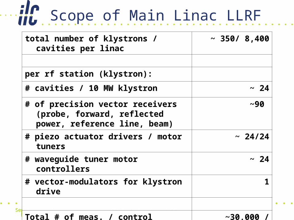
Scope of Main Linac LLRF
total number of klystrons / cavities per linac ~ 350/ 8,400
per rf station (klystron):
# cavities / 10 MW klystron ~ 24
# of precision vector receivers (probe, forward, reflected power, reference line, beam)
~90
# piezo actuator drivers / motor tuners ~ 24/24
# waveguide tuner motor controllers ~ 24
# vector-modulators for klystron drive 1
Total # of meas. / control channels per linac ~30,000 / ~30,000

September 20-22, 2006 MAC Review Global Design Effort 10
Requirements
• Reliability• not more than 1 LLRF system failure / week• minimize LLRF induced accelerator downtime• Redundancy of LLRF subsystems• ...
• Operability• “One Button” operation (State Machine)• Momentum Management system• Automated calibration of vector-sum• ...
• Reproducible• Restore beam parameters after shutdown or interlock trip• Recover LLRF state after maintenance work• ...
September 20-22, 2006 MAC Review Global Design Effort 11
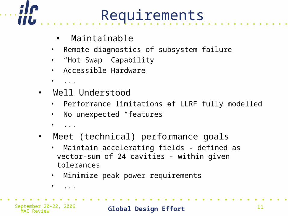
Requirements
• Maintainable• Remote diagnostics of subsystem failure
• “Hot Swap” Capability
• Accessible Hardware
• ...
• Well Understood• Performance limitations of LLRF fully modelled
• No unexpected “features”
• ...
• Meet (technical) performance goals• Maintain accelerating fields - defined as vector-sum of 24
cavities - within given tolerances
• Minimize peak power requirements
• ...

September 20-22, 2006 MAC Review Global Design Effort 12
Sources of Perturbations
o Beam loading o Cavity dynamics
- Beam current fluctuations - cavity filling
- Pulsed beam transients - settling time of field
- Multipacting and field emission
- Excitation of HOMs o Cavity resonance frequency change
- Excitation of other passband modes - thermal effects (power dependent)
- Wake fields - Microphonics
- Lorentz force detuning
o Cavity drive signal
- HV- Pulse flatness o Other
- HV PS ripple - Response of feedback system
- Phase noise from master oscillator - Interlock trips
- Timing signal jitter - Thermal drifts (electronics, power
- Mismatch in power distribution amplifiers, cables, power
transmission system)

September 20-22, 2006 MAC Review Global Design Effort 13
RF System Architecture (Simplified)
September 20-22, 2006 MAC Review Global Design Effort 14
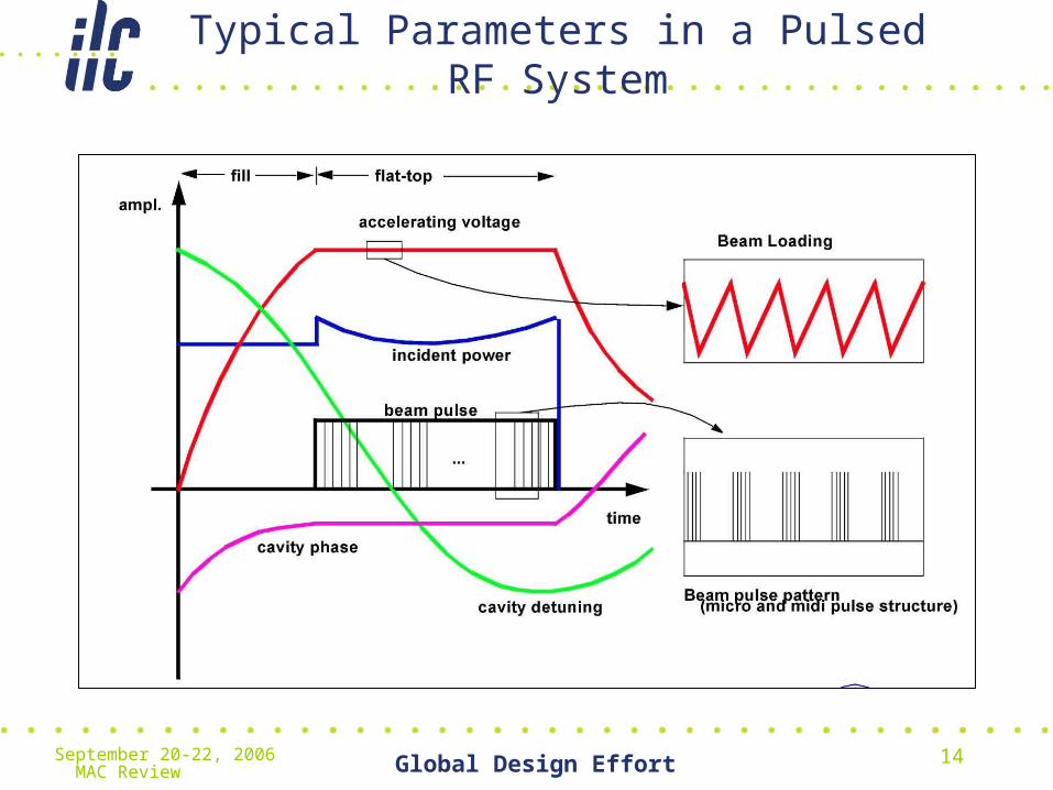
Typical Parameters in a Pulsed RF System
September 20-22, 2006 MAC Review Global Design Effort 15
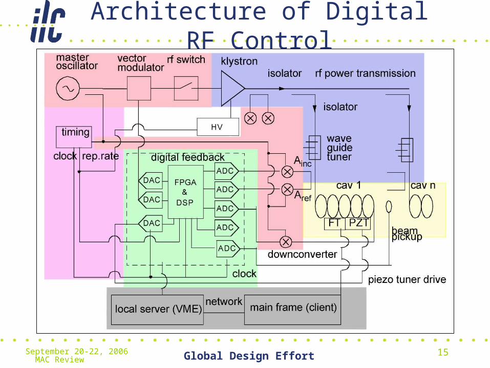
Architecture of Digital RF Control

September 20-22, 2006 MAC Review Global Design Effort 16
Error Map
Normalized
Perturbation
Residual Error
September 20-22, 2006 MAC Review Global Design Effort 17
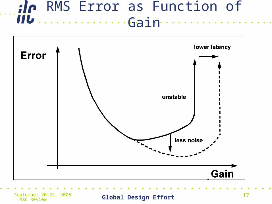
RMS Error as Function of Gain
September 20-22, 2006 MAC Review Global Design Effort 18
Field Regulation at FLASH

September 20-22, 2006 MAC Review Global Design Effort 19
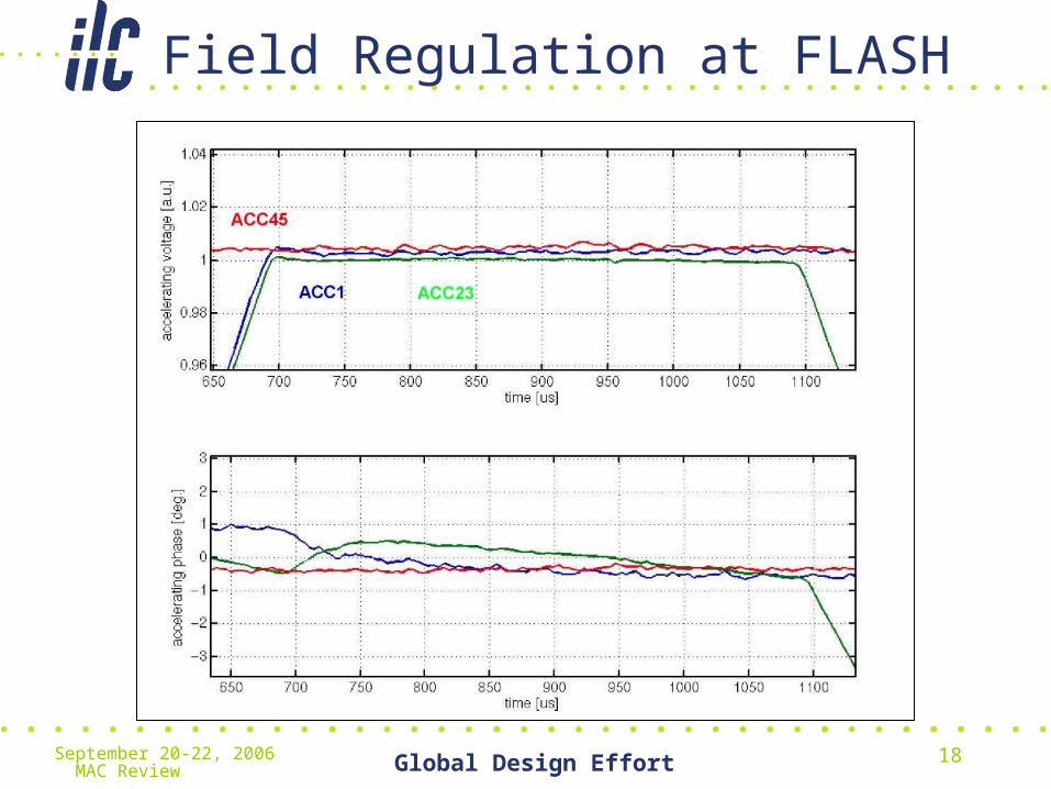
Field Regulation at FLASH
September 20-22, 2006 MAC Review Global Design Effort 20
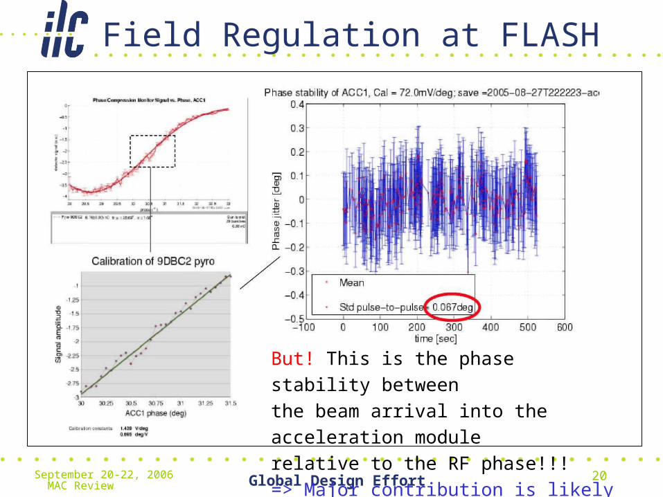
Field Regulation at FLASH
But! This is the phase stability between
the beam arrival into the acceleration module
relative to the RF phase!!!
=> Major contribution is likely from laser
September 20-22, 2006 MAC Review Global Design Effort 21
Challenges for RF Control
• Topics– Vector-Sum Calibration (Ampl. & Phase)– Operation close to performance limits– Exception Handling– Automation of operation– Piezo tuner lifetime and dynamic range– Optimal field detection and controller (robust)– Operation at different gradients– Defining stándards for electronics (such as
ATCA)– Interfaces to other subsystems– Reliability
September 20-22, 2006 MAC Review Global Design Effort 22
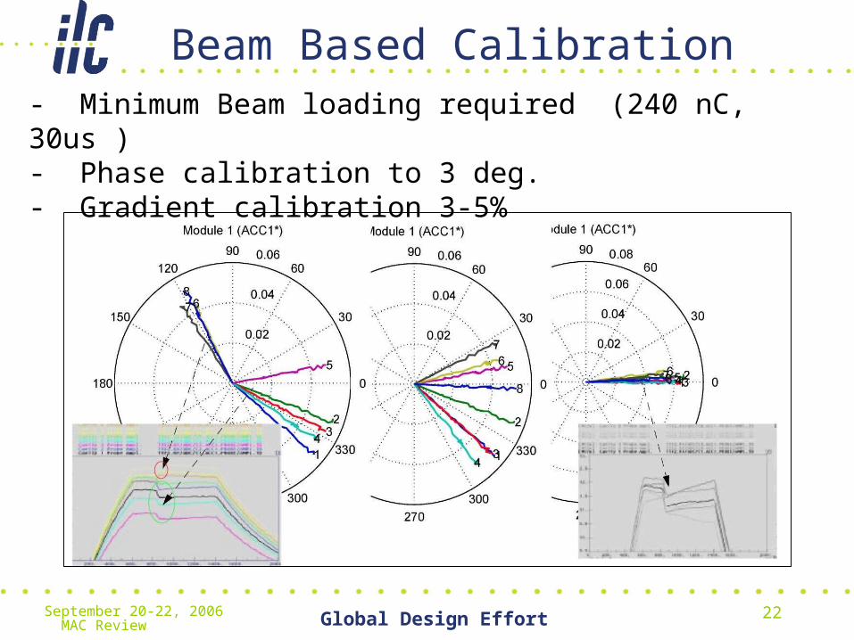
Beam Based Calibration- Minimum Beam loading required (240 nC, 30us )- Phase calibration to 3 deg.- Gradient calibration 3-5%
September 20-22, 2006 MAC Review Global Design Effort 23
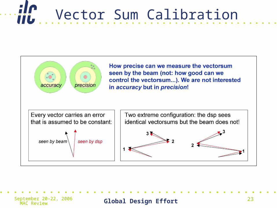
Vector Sum Calibration
September 20-22, 2006 MAC Review Global Design Effort 24
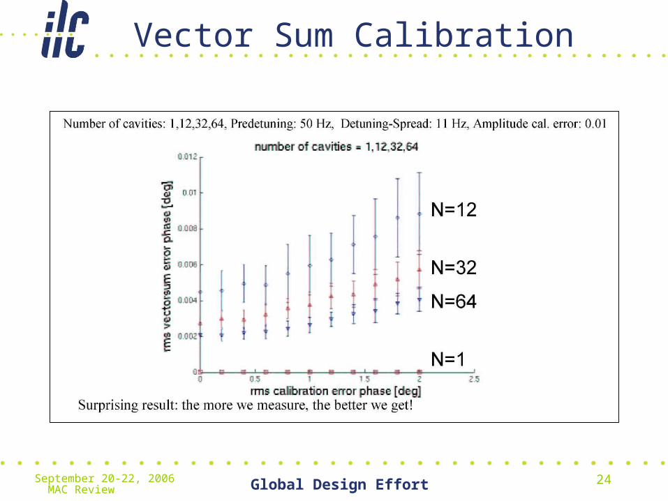
Vector Sum Calibration

September 20-22, 2006 MAC Review Global Design Effort 25
Automation ex.: Adapt. Feedforward

September 20-22, 2006 MAC Review Global Design Effort 26
Operation at Different Gradients
September 20-22, 2006 MAC Review Global Design Effort 27
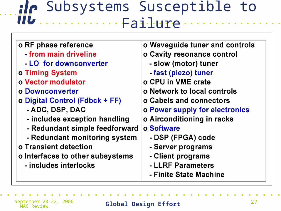
Subsystems Susceptible to Failure

September 20-22, 2006 MAC Review Global Design Effort 28
Reliability

September 20-22, 2006 MAC Review Global Design Effort 29
Evolution of Hardware at SNS

September 20-22, 2006 MAC Review Global Design Effort 30
Lesson Learned
• Document the system requirements.– Avoid feature creep.
• Document the development plan.• Make a resource-loaded schedule and budget.• Use proven solutions. Don’t reinvent the wheel. Resist the “not
invented here” syndrome.• Keep it simple.• If your schedule is at risk, ask for help.• Your team must “take ownership” of the system.• Software support and development is an integral and essential
part of the process.• Be willing to cross functional and subsystem boundaries.• Avoid dictating the choice of software tools and languages if
possible. Ref. M. Champion

September 20-22, 2006 MAC Review Global Design Effort 31
Advice for Hardware Development
• Avoid early parts obsolescence.• Install a RF PIN switch diode on your RF output.• Install extra channels – you will need them later!• Verify your parts can withstand a wet wash process following SMT
assembly.• Do not use epoxy-mount components (difficult to replace)• Provide adequate shielding between motherboard and daughterboard.• Provide “clean” DC power to your circuits.
– Beware of DC-to-DC switching supplies. The switching frequency (usually 200 kHz) will find its way into your system!
• Don’t waste your time building cables. Let a vendor do it.• Use a symmetric layout for your ADC clock distribution and pay
attention to impedance matching.• Think about how you will test, troubleshoot and repair your circuit
boards when you do your board design and layout (not after you receive the circuit boards)
Ref.: M. Champion

September 20-22, 2006 MAC Review Global Design Effort 32
RF Station with 3 Cryo-modules

September 20-22, 2006 MAC Review Global Design Effort 33
Rack Layout

September 20-22, 2006 MAC Review Global Design Effort 34
LLRF Rack Detail

September 20-22, 2006 MAC Review Global Design Effort 35
3 Cryomodule Field Controller
September 20-22, 2006 MAC Review Global Design Effort 36
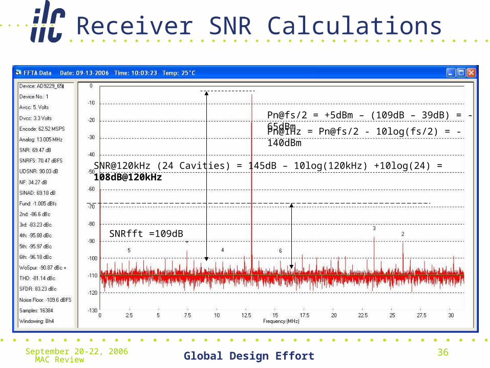
Receiver SNR Calculations
SNRfft =109dB
Pn@fs/2 = +5dBm – (109dB – 39dB) = -65dBm
Pn@1Hz = Pn@fs/2 - 10log(fs/2) = -140dBm
SNR@120kHz (24 Cavities) = 145dB – 10log(120kHz) +10log(24) = 108dB@120kHz

September 20-22, 2006 MAC Review Global Design Effort 37
DESY SIMCON3.1 Controller
September 20-22, 2006 MAC Review Global Design Effort 38
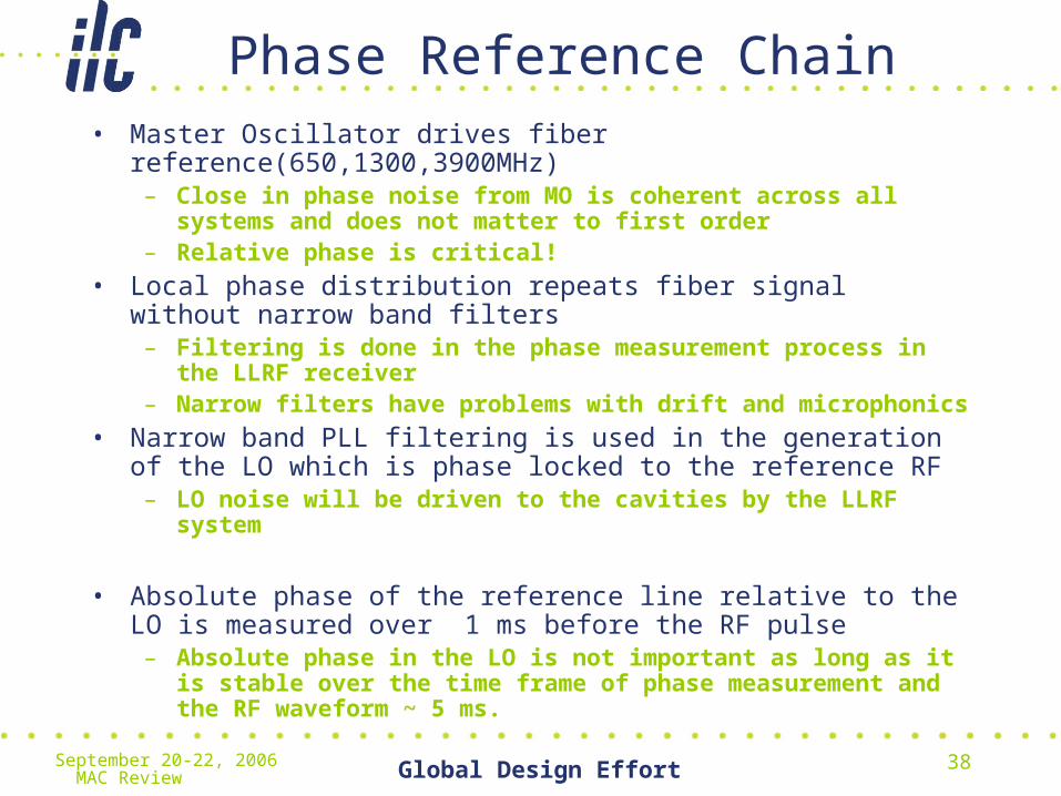
Phase Reference Chain• Master Oscillator drives fiber reference(650,1300,3900MHz)
– Close in phase noise from MO is coherent across all systems and does not matter to first order
– Relative phase is critical!
• Local phase distribution repeats fiber signal without narrow band filters– Filtering is done in the phase measurement process in the LLRF
receiver– Narrow filters have problems with drift and microphonics
• Narrow band PLL filtering is used in the generation of the LO which is phase locked to the reference RF
– LO noise will be driven to the cavities by the LLRF system
• Absolute phase of the reference line relative to the LO is measured over 1 ms before the RF pulse
– Absolute phase in the LO is not important as long as it is stable over the time frame of phase measurement and the RF waveform ~ 5 ms.
September 20-22, 2006 MAC Review Global Design Effort 39
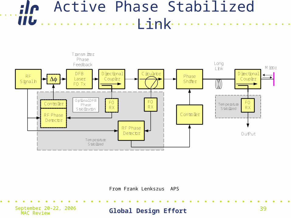
Active Phase Stabilized Link
RF Signal In
DFB LaserFO Tx
FO RX
RF Phase Detector
CirculatorPhase Shifter
Directional Coupler
Mirror
FO RX
Controller
Long Link
FO RX
OutPut
Directional CouplerDf
Transmitter Phase
Feedback
TemperatureStabilized
TemperatureStabilized
RF Phase Detector
Optional DFB Phase
Stabilization
Controller
From Frank Lenkszus APS

September 20-22, 2006 MAC Review Global Design Effort 40
Sector Timing Controller
5 Hz Fiduicial
Phase Reference to LLRF and Timing
Event System
GPS
Global Event System
5 Hz FiduicialPhase
Reference
Event Receiver
Event Generator
Local Event List
Diagnostics
Processor
52 MHz
LO to LLRF
From Frank Lenkszus APS
September 20-22, 2006 MAC Review Global Design Effort 41
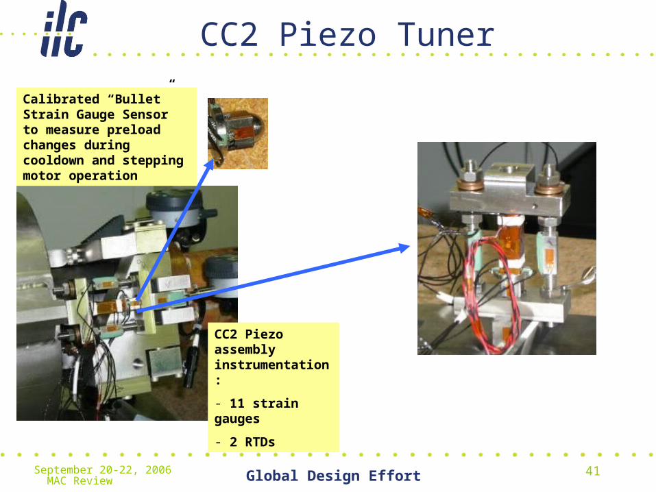
CC2 Piezo Tuner
Calibrated “Bullet” Strain Gauge Sensor to measure preload changes during cooldown and stepping motor operation
CC2 Piezo assembly instrumentation:
- 11 strain gauges
- 2 RTDs

September 20-22, 2006 MAC Review Global Design Effort 42
Piezo Test as a Vibration Sensor – CW mode
Piezo Tuner & RF Mixer Measurement of CC2 @10W CW Mode
There is a good correlation between the Piezo Tuner and the RF Mixer in the time domain.
An FFT of the Piezo Tuner and the RF Mixer signals show close agreement in the frequency domain.

September 20-22, 2006 MAC Review Global Design Effort 43
Real Time Cavity Simulator
Justin Keung, UPenn
September 20-22, 2006 MAC Review Global Design Effort 44
Automation
• Large number of stations require-– System diagnostics must be mostly automated– Expert diagnostics must be carried out
remotely through the control system– Error and fault detection and failure prediction
• Track klystron gain
– Self test• On reboot and schedule
– Auto Calibration• Built in “Network Analyzer” receiver calibration• Klystron linearizer calibration• Beam based cavity vector calibration
September 20-22, 2006 MAC Review Global Design Effort 45
Software Modules
1. Control Algorithms (Fdbck/ Feedforward)
2. Meas. QL and detuning
3. Cavity Frequency Control (Fast and Slow)
4. Amplitude/Phase Calibration
5. Vector-Sum Calibration
6. Loop phase and loop gain
7. Adaptive Feedforward
8. Exception Handling
9. Klystron Linearization
10.Lorentz Force Compensation
September 20-22, 2006 MAC Review Global Design Effort 46
LLRF Collaboration
• DESY, Warsaw ELHEP, KEK, FNAL(CD,AD,TD), LBL,SNS, SLAC, JLAB,University of Pennsylvania
• Weekly telecom for LLRF• Weekly telecom for Controls• Weekly telecom for HLRF• Major design efforts underway for XFEL and test
string at FNAL– Several high performance controllers being developed– Master Oscillator and distribution– Real time Cavity Simulator
September 20-22, 2006 MAC Review Global Design Effort 47
Uncharted Waters(what looks tough)
• Large system scale– All the issues of automation and getting it done right the
first time– Phase reference and distribution over long paths
• Identifying single point failures and adding redundancy where needed– Example -LO and reference distribution
• Vector sum calibration– Accuracy - each system wide calibration will introduce a
systematic error.
• Beam based feedback– Phase and energy at IP– Feedback to Crab Cavity vector control
September 20-22, 2006 MAC Review Global Design Effort 48
References• “ILC Timing”, ILC-doc-158-V1, Lenkszus, APS
• “Status of the Penn C-based ILC Cavity Simulator”, Justin Keung, University of Pennsylvania
• “Recent Developments and Layout of the Master Laser System for the VUV-FEL”, A. Winter, F. Ö. Ilday, H. Schlarb, F. X. Kaertner, DESY Hamburg, Bilkent University, MIT 16.05.2006
• “Digital Low-Level RF Control for Future Superconducting Linear Colliders”, S. Simrock, PAC 2005
• “Achieving Phase and Amplitude Stability in Pulsed Superconducting Cavities”, S. Simrock, PAC 2001
• “LLRF of Low Level RF System for the J-PARC LINAC”. S. Michizono, LINAC 2004