Global Design Effort - CFS for Asian Single Tunnel Configuration Design Progress Masanobu Miyahara...
20
Global Design Effort - CFS International Workshop on Linear Colliders 2010 1 for Asian Single Tunnel Configuration Design Progress Masanobu Miyahara KEK
-
Upload
buck-malone -
Category
Documents
-
view
218 -
download
1
Transcript of Global Design Effort - CFS for Asian Single Tunnel Configuration Design Progress Masanobu Miyahara...

Global Design Effort - CFS
International Workshop on Linear Colliders 2010 1
for Asian Single Tunnel Configuration
Design Progress
Masanobu Miyahara
KEK
Global Design Effort - CFS
International Workshop on Linear Colliders 2010 2
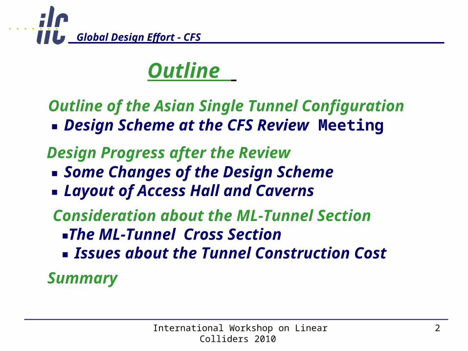
Outline of the Asian Single Tunnel Configuration ■ Design Scheme at the CFS Review Meeting
Design Progress after the Review ■ Some Changes of the Design Scheme ■ Layout of Access Hall and Caverns
Consideration about the ML-Tunnel Section ■The ML-Tunnel Cross Section ■ Issues about the Tunnel Construction Cost
Summary
Outline
Global Design Effort - CFS
International Workshop on Linear Colliders 2010 3
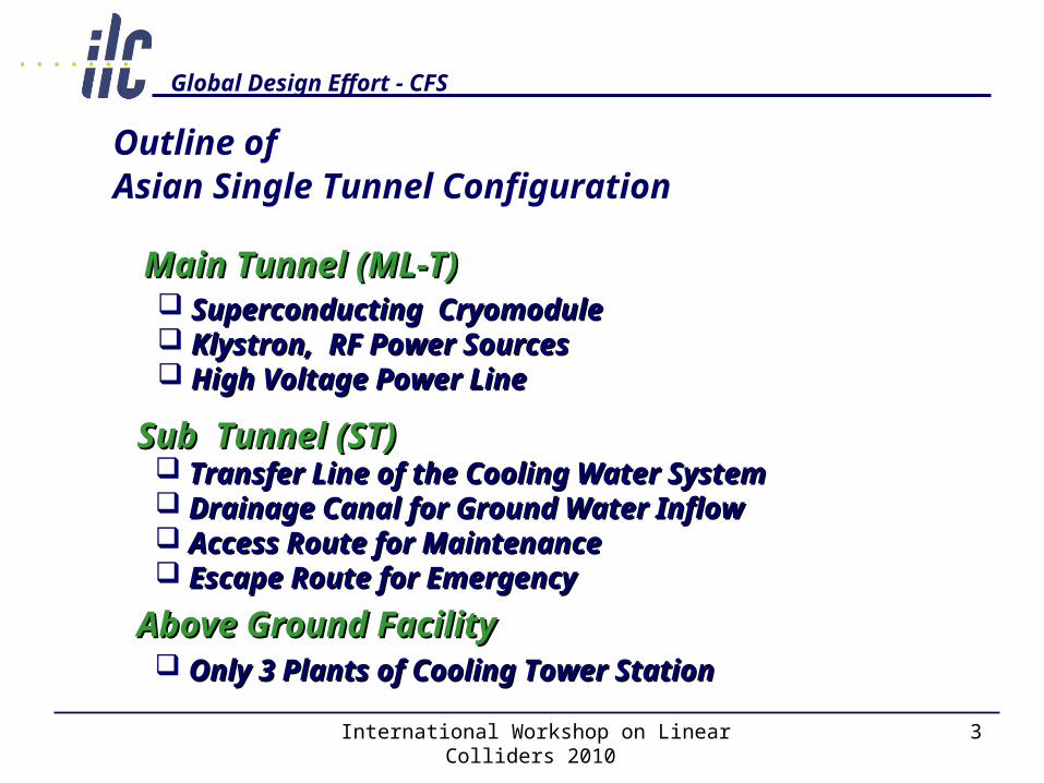
Outline of
Main Tunnel (ML-T)Main Tunnel (ML-T)
Sub Tunnel (ST)Sub Tunnel (ST)
Superconducting CryomoduleSuperconducting Cryomodule Klystron, RF Power SourcesKlystron, RF Power Sources High Voltage Power LineHigh Voltage Power Line
Transfer Line of the Cooling Water SystemTransfer Line of the Cooling Water System Drainage Canal for Ground Water Inflow Drainage Canal for Ground Water Inflow Access Route for MaintenanceAccess Route for Maintenance Escape Route for Emergency Escape Route for Emergency
Asian Single Tunnel Configuration
Above Ground FacilityAbove Ground Facility Only 3 Plants of Cooling Tower StationOnly 3 Plants of Cooling Tower Station

Global Design Effort - CFS
International Workshop on Linear Colliders 2010 4
Overal Facility Layout : after completion
30km
Main (Sub) Tunnel
Cryogenic Cavern (AH)
Cooling Tower Station
Access Tunnel (Shaft)
Low voltage Cavern
Cooling Tower Station (surface)

Global Design Effort - CFS
International Workshop on Linear Colliders 2010 5
Tunnel Spacing (ML-T & Sub-T)
φ
φ
φ
φφ
6, 1401703005, 200300170
4, 500
1001004, 100100 100
4,500
615
200
2,500
750
435
( φ 500× 2)
( φ 900× 2)
送 水 管
冷 却 水 管
支 保 +吹 付 コンクリー ト
( t =300)
防 水 シ ー ト
( φ 300)
路 盤 コンクリー ト
イ ン バ ー ト ブ ロ ッ ク
覆 工 コ ン ク リ ー ト
縦 断 排 水 管
(プ レ キ ャ ト )
( B=1500, D=250~ 750)
縦 断 排 水 路 ( 開 水 路 )
(勾 配 =0. 1%)
( t =100)一 次 吹 付 コンクリー ト
二 次 吹 付 コンクリー ト( t =100)
1,200
1, 200
1,150
300
6,140
170
300
φ2,600
本 坑
370
標 準 断 面
3,000
50
14, 650
10, 000
サブトンネル
Isolation Distance 10.0m
3.0m
5.2m
4.1m
Track Bed ConcreteCooling WaterDrainage Canal
ML-Tunnel
Sub-Tunnel
Global Design Effort - CFS
International Workshop on Linear Colliders 2010 6
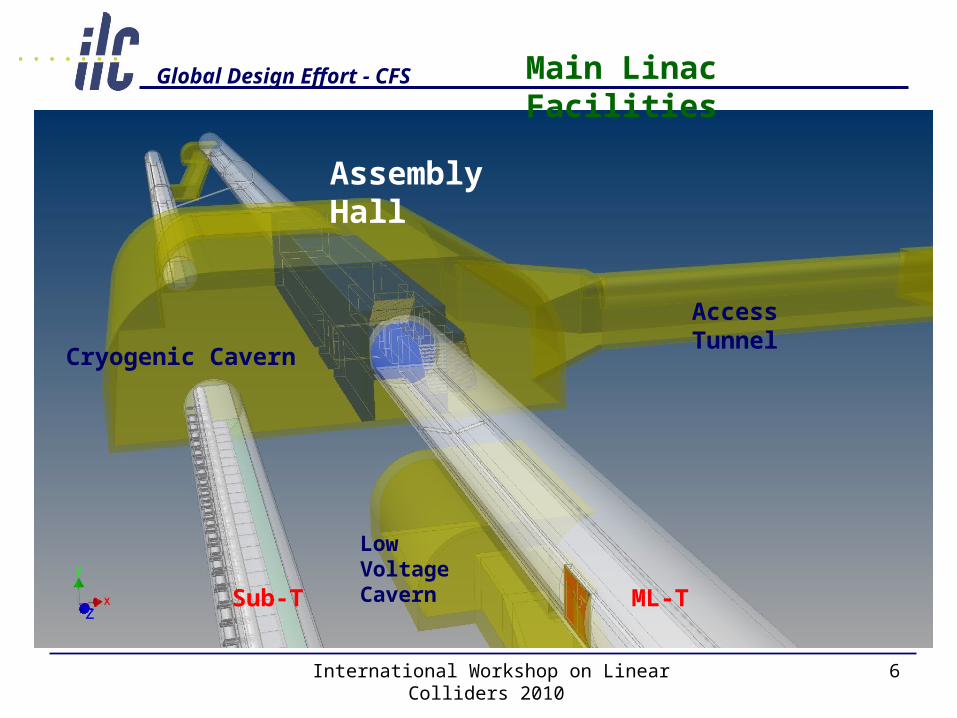
Access Tunnel
Cryogenic Cavern
Low Voltage Cavern
Assembly Hall
ML-TSub-T
Main Linac Facilities

Global Design Effort - CFS
International Workshop on Linear Colliders 2010 7
■ Some Changes of the Design Scheme
■ Overall Facility Layout of ML-T
Design Progress after the Review

Global Design Effort - CFS
International Workshop on Linear Colliders 2010 8
Point Number of the Cooling Tower Farm 3Plants ⇒ 6 plants
Review of the Temperature Condition of the Cooling Water Circulation Loop to the Various Component
Primary Loop : Δ t =10℃ ⇒ Δ t =20℃ Secondary Loop: Δ t =5℃ ⇒ Δ t =10℃
Placement of the Machine Room (Local Cavern) about 600m intervals in the Main Linac Tunnel Corresponding to the 16 RF unit of Main Linac.
Review the Heat Energy Flow Review the Heat Energy Flow
Design Progress (1)

Global Design Effort - CFS
International Workshop on Linear Colliders 2010 9
2K and 4K Ref. Cold Boxes are Installed in the Same Cryogenic Cavern at 5 km Intervals.
Cryogenic Cavern must be Connected in the Terminal Area of the Access Tunnel.
- Large component such as Ref. Cold boxes and He. Compressor Units are Installed via Access tunnel - This Access Tunnel holds enough big Section to Carry a Construction Machine such as TBM others.
When a Helium Gas Leak Occurred We can Secure the Escape Route to Two Direction via a Sub-tunnel.
Layout of Cryogenic Facility and Cavern Layout of Cryogenic Facility and Cavern
Design Progress (2)
Global Design Effort - CFS
International Workshop on Linear Colliders 2010 10
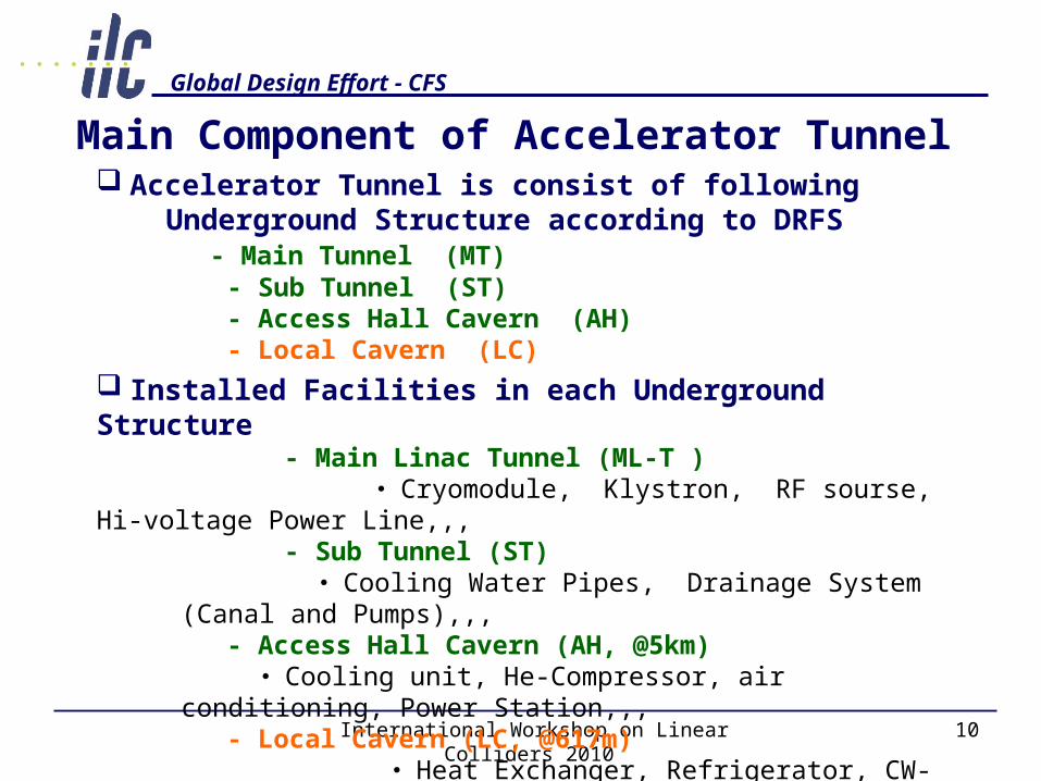
Main Component of Accelerator Tunnel Accelerator Tunnel is consist of following Underground Structure according to DRFS
- Main Tunnel (MT) - Sub Tunnel (ST) - Access Hall Cavern (AH) - Local Cavern (LC)
Installed Facilities in each Underground Structure - Main Linac Tunnel (ML-T ) ・ Cryomodule, Klystron, RF sourse, Hi-voltage Power Line,,, - Sub Tunnel (ST)
・ Cooling Water Pipes, Drainage System (Canal and Pumps),,, - Access Hall Cavern (AH, @5km) ・ Cooling unit, He-Compressor, air conditioning, Power
Station,,, - Local Cavern (LC, @617m)
・ Heat Exchanger, Refrigerator, CW-Pumps, Booster Pumps, Air Conditioning System, Sub Station, other Utility Facilities,,,
Global Design Effort - CFS
International Workshop on Linear Colliders 2010 11
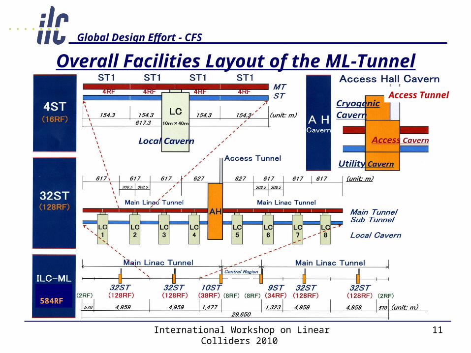
Overall Facilities Layout of the ML-Tunnel
Access Tunnel
584RF
Global Design Effort - CFS
International Workshop on Linear Colliders 2010 12
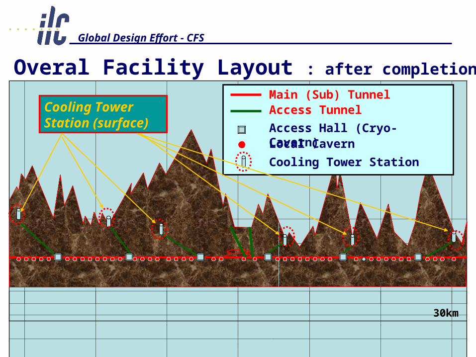
Overal Facility Layout : after completion
30km
Main (Sub) Tunnel
Access Hall (Cryo-Cavern)
Cooling Tower Station
Access Tunnel
Local Cavern
Cooling Tower Station (surface)

Global Design Effort - CFS
International Workshop on Linear Colliders 2010 13
Layout Image of Cavern and ML-T
Access TunnelCryogenic Cavern
Local Cavern
AH Main Linac Tunnel
He Compressor
4K-Cold Box
2K-Cold Box

Global Design Effort - CFS
International Workshop on Linear Colliders 2010 14Cross Section
Bird’s-eye View
Local Cavern: Scale and Structure
Plan
Section Detail
10.0m40.0m
Local Cavern
ML-T
Sub-T
11.0m
Global Design Effort - CFS
International Workshop on Linear Colliders 2010 15
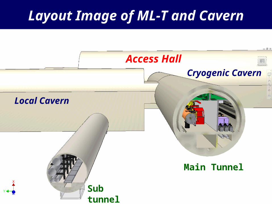
Layout Image of ML-T and Cavern
Main Tunnel
Local Cavern
Access HallCryogenic Cavern
Sub tunnel
Global Design Effort - CFS
International Workshop on Linear Colliders 2010 16
Consideration about the ML-Tunnel Section
■ Investigation about the ML-T Cross Section
■ Execution Cost of the TBM Tunnel

Global Design Effort - CFS
International Workshop on Linear Colliders 2010 17
Consideration about the ML-T Cross Section Comparison by the Shape, Construction Method
Shape Circle Type Bullet TypeMethod TBM NATM
ConstructionSpeed
High speed excavation in case of suitable geological condition
Middle-level (150m/Month)
CostDepend on tunnel lengthHigh cost in case of shortdistance
Not depend on tunnel lengthLow cost in case of shortDistance
Adaptability for Cavern excavation
Special construction machine should be developed because of circular arc floor
General-use construction machine can be applied because of flat floor
Noise and Vibration
Small level
Larger level than TBMAlmost reduced in deep level

Global Design Effort - CFS
International Workshop on Linear Colliders 2010 18
Consideration from the Viewpoint of
Tunnel Construction ● Main Tunnel are used for Local Cavern Construction after the Digging Completion
- Mucking way from Local Cavern - Passageway of Construction Machine and Vehicle for Local Cavern - Air Ventilation, Water Supply Line, Drainage line, Power Supply,,,
● In case of Circle Shape (TBM) - Limitation for the Traffic of Construction Machine and Vehicle is extremely severe
● In case of Bullet Shape (NATM) - General-use Machines and Vehicles can
pass through easily
TBM
NATM
Ventilation
Water Supply Drainage

Global Design Effort - CFS
International Workshop on Linear Colliders 2010 19
Issue about the Tunnel Construction CostComparison of TBM and NATM
● TBM Execution - High Speed Excavation (low cost excavation) will be Possible in case of the Good geological Condition - Not Economical in a Short Distance Execution, Because the Portion of TBM Machine Cost is Large - As for the Tunneling of TBM Excavation, a Merit is bigger in case of Long-Distance Execution more than 10km
● NATM Execution
- Construction Cost doesn’t Depend on Excavation Distance
as much as TBM, because General-use Machines are Applied.
Global Design Effort - CFS
International Workshop on Linear Colliders 2010 20
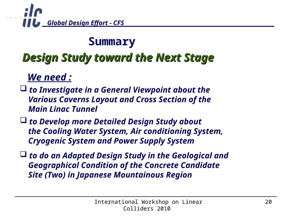
to Investigate in a General Viewpoint about the Various Caverns Layout and Cross Section of the Main Linac Tunnel to Develop more Detailed Design Study about the Cooling Water System, Air conditioning System, Cryogenic System and Power Supply System
Summary
Design Study toward the Next StageDesign Study toward the Next Stage
to do an Adapted Design Study in the Geological and Geographical Condition of the Concrete Candidate Site (Two) in Japanese Mountainous Region
We need :