Glider’s Plywood House
46
Glider’s Plywood House Master’s Thesis Isak Regnström
Transcript of Glider’s Plywood House

Glider’s Plywood House
Master’s ThesisIsak Regnström


Glider’s Plywood House
A Master’s Thesis project by Isak Regnström
Examiner: Morten LundTutor: Mika Määttä
Completed in autumn 2014

Contents
Abstract 1Introduction 2Activities on the field 4The Club House 6Tools and Materials 8wikiHouse 10Facit Homes 11Process 12Design 20Site plan, 1:1000 22Building plan, 1:100 24East elevation, 1:100 26Section B-B, 1:100 27South elevation, 1:100 28Section A-A, 1:100 30Construction 32Roof and ceiling 34Outer Walls and Pillars 36Foundations and Floor 38Final Thoughts 41
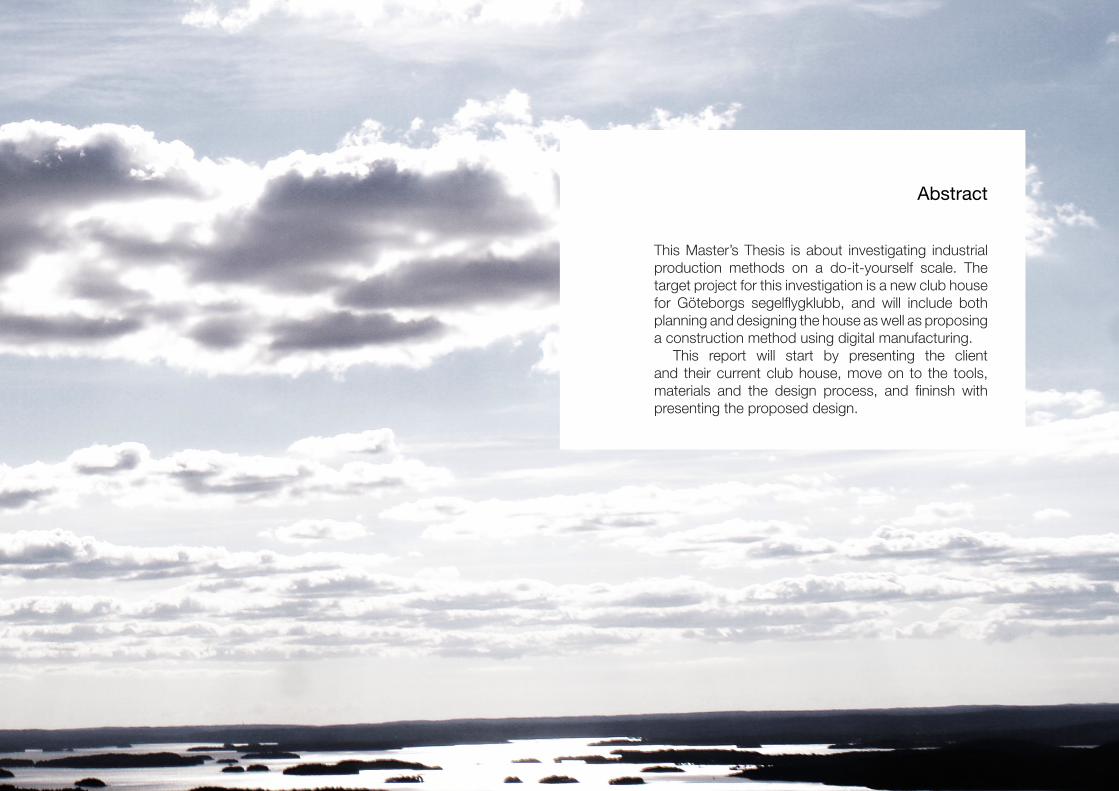
Abstract
This Master’s Thesis is about investigating industrial production methods on a do-it-yourself scale. The target project for this investigation is a new club house for Göteborgs segelflygklubb, and will include both planning and designing the house as well as proposing a construction method using digital manufacturing.
This report will start by presenting the client and their current club house, move on to the tools, materials and the design process, and fininsh with presenting the proposed design.

Introduction
The club’s airfield is located in a rural area outside of Alingsås, on a site with mostly grass. The landing strip takes up the majority of the field, and the rest is used for airplane parking, camping and other outdoor activities.


East elevation, 1:100
4
Activities on the field
The area just outside the club house acts as a gathering point during daily activities, and is the place where most members hang out between flights. The club house has a patio with a canopy and a path of stone tiles, the rest is grass.

5

Plan, 1:100
6
The Club House
The club house acts as a hub where people can store their belongings while flying or working on the field. Administration such as logging flight, checking the weather and booking the airspace for flying goes on continuously throughout the day. There is a classroom for training new pilots and an office. The building has sanitary spaces with batrooms, showers and laundry machines.

7
8
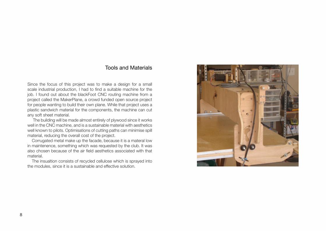
Tools and Materials
Since the focus of this project was to make a design for a small scale industrial production, I had to find a suitable machine for the job. I found out about the blackFoot CNC routing machine from a project called the MakerPlane, a crowd funded open source project for people wanting to build their own plane. While that project uses a plastic sandwich material for the components, the machine can cut any soft sheet material.
The building will be made almost entirely of plywood since it works well in the CNC machine, and is a sustainable material with aesthetics well known to pilots. Optimisations of cutting paths can minimise spill material, reducing the overall cost of the project.
Corrugated metal make up the facade, because it is a materal low in maintenence, something which was requested by the club. It was also chosen because of the air field aesthetics associated with that material.
The insualtion consists of recycled cellulose which is sprayed into the modules, since it is a sustainable and effective solution.

Metal facade
Plywood skeleton
Fiber insulation
9

10
wikiHouse
WikiHouse is an open source project about building simple houses with a CNC machine. The designs are for the same CNC machine as I’ve chosen to use. Their method of construction is to build sections of the
houses flat on the ground and then connect them to create a continous house body. The frame is then fitted with installations and insulation and covered with panels.
The wikiHouse project aims to create a
library where anyone can pick the pieces for their own project and cut out the pieces themselves.

11
Facit Homes
Factit Homes is a house building company in Great Britain, and their focus is also on machine production of building components. They build houses by transporting a portable factory with a CNC machine in a container
to the site. They then cut out pieces which are assembled into boxes and stacked next to each other to create walls. Other boxes are fitted between the roof and floor beams. All boxes are then filled with loose insulation
and the surfaces are then treated much like a regular stud wall when applying the facade and surface treatments indoors.

Process
The investigations that went into the design involved folding and scrunching paper as well as cardboard models.


14
In the first investigations I scrunched up a piece of paper and looked at the resulting folds in small areas. My intention to find a design concept and to give me hints for construction priciples.
The next investigation was to try controlled deformation. These papers were scrunched with either fixed positions of my fingers, or fixed directions of the scrunch, or both.
The last investigation was made to examine what happens when you take out a piece of paper and tape it back together. This produced doubly curved surfaces, something I could not use further in this project.

15

16
I made some concept models where I tried out what kind of patterns and structures could be achieved with folded surfaces. The folds greatly improved strength along the folds, but needs reinforcement or they will collapse into a flat plane.

17

18
The last models were built in scale, and are more similar to a real building structural system. I wanted to investigate how to integrate sky lights in the design, as well as try out my design principles in a more advanced system than before.

19
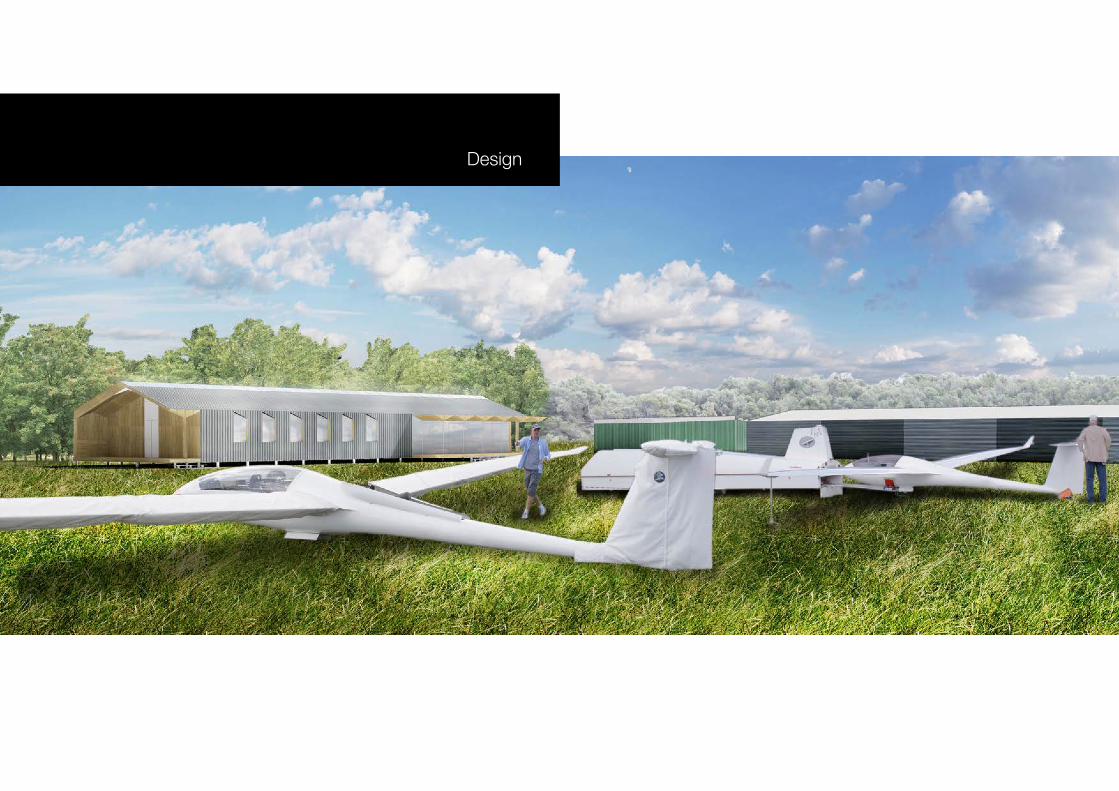
Design


N
22
Site plan, 1:1000
The club house is located in the same location as the old one; along the northern edge of the camping/parking lawn.

N
23

N
24
Building plan, 1:100
The building has a main room for club activities, mostly working as a living room. It is sectioned off into two smaller rooms which are the classroom and the office. The classroom can be closed to allow classes during other club activities. A central corridor connects the scullery in the back to the main room, and along this corridor are bedrooms and changing rooms with showers and saunas.
A

N
25B
B
A

26
East elevation, 1:100
The entrance is located closest to the entrance of the field, and the facade is entirely plywood.

27
Section B-B, 1:100
The skylight also lights up the smaller rooms located along the central corridor.

28
South elevation, 1:100
The south side of the house has a patio with a canopy facing the lawn. The facade is mostly corrugated metal with some plywood.
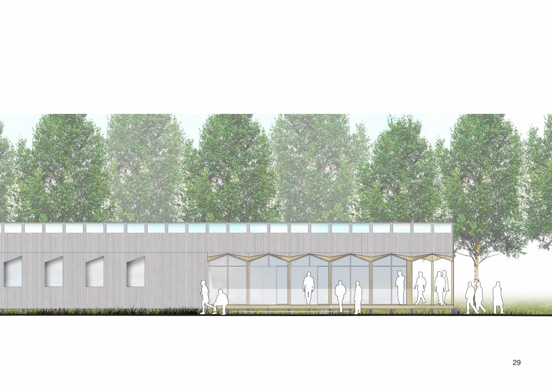
29

30
Section A-A, 1:100
The building’s central axis has a row of skylights running all the way through the building.

31

32
Construction
The building is designed to be built by the club members themselves using a CNC routing machine. The design features a modular system with some key pieces which can be modified to change the position of windows for example.

33

34
Roof and ceiling
The roof modules are made up of a central beam with a plywood web and stud flanges. The ceiling surface is folded to improve the strength of the whole element and to create an undulating surface for aesthetics. Triangular pieces extruding from the beam lock the angle of the folds in place and carry the load of the cieling into the beam.
Exploded roof module

35
Roof modules
Masonite
Lath
Corrugated metal
Skylight

36
Outer Walls and Pillars
The outer walls consist of modules with a central vertical piece, some horizontal pieces and sheets to cover them as well as house the insulation. One of the sheets can be left out to leave an opening for windows. The top of the module connects to the roof modules.
The pillar modules are similar but instead of sheets covering the spaces, they leave large openings for glass walls and doors. The central piece is reinforced by additional plywood.
Wall componentsExploded wall module

37
Exploded pillar module
Row of pillars

38
Foundations and Floor
The building stands on a foundation of large metal screws drilled into the ground. On these lay wooden beams which hold the floor modules. These modules are boxes with an additional piece along the center for reinforcement.
Exploded floor module
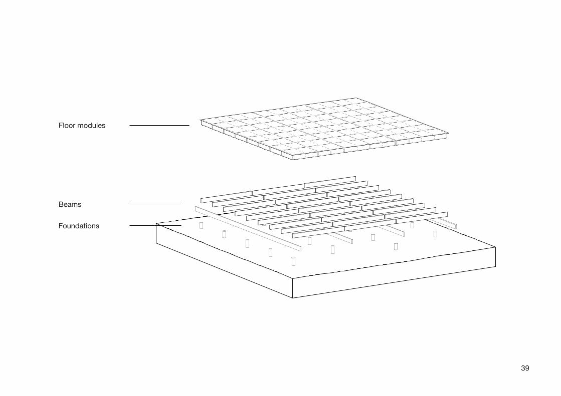
39
Foundations
Beams
Floor modules

40

41
Final Thoughts
This thesis project started with the intetions of designing a small house for a glider club. The purpose was to investigate how they could build it themselves with innovative building methods while keeping costs and work hours low. What followed was a series of investigations into the relationships between conceptual design and the physically built, between aesthetics and structural integrity. I’ve learned a lot about all the different aspects of building a house, and how that can both help and hamper the design process.
Being from the Architecture and Engineering programme, I wanted my Master’s Thesis have a tone of both architectural design and structural design. I have struggled a lot with the relations between construction and concept, and I find that valuable. A building’s structure can be a beautiful thing, and I wanted to embrace that both in aesthetics and in function.