GLC-GLH GLC linear control units unità di guida per cilindri -di... · The unit is supplied...
8
A-51 CILINDRI PNEUMATICI PNEUMATIC CYLINDERS The linear control units GLC and GLH series can be assembled to cylinders in compliance with ISO 6432 and ISO 15552 standards. Anti-rotation is guaranteed by two steel guide stems, whose movement is supported by four brass bushes in GLC ... and GLH ... BS series, and by four ball bushings in the GLH ... BB series. The piston rod is connected to the front flange by a floating joint. The use of high quality materials and precision manufacturing techniques gives the units excellent performance with high resistance to side loads. Versatility of mounting is assurred by either mounting directly to the unit, or by the use of standard accessories (mountings). All the linear control units GLH-BS and BB series are supplied with scraper seals and grease box. The unit is supplied already lubricated. Le unità di guida serie GLC e GLH sono assemblabili a cilindri rispondenti alla norma ISO 6432-15552. L’ antirotazione è garantita da due steli guida in acciaio il cui movimento è supportato da quattro bronzine a strisciamento nella serie GLC ... e GLH ... BS, oppure da quattro cuscinetti con ricircolo di sfere nella serie GLH ... BB. Lo stelo del cilindro è collegato alla flangia frontale con un giunto di compensazione assiale e radiale. L’ impiego di materiali di alta qualità e la precisione delle lavorazioni consentono all’unità di guida una ottima resistenza ai carichi laterali con elevate prestazioni. La versatilità d’ impiego è stata realizzata mediante tre possibili superfici di fissaggio e di piastre per il fissaggio orizzontale o verticale. Tutte le unità di guida, oltre ad essere fornite già prelubrificate, sono corredate di rischiapolvere ed ingrassatori. TECHNICAL FEATURES / CARATTERISTICHE COSTRUTTIVE - Avoid impacts and abrasion of slide rods. - Avoid impacts and scratching of the slide body and plate surfaces in order not to effect the flatness of the slide. - Ensure that the surface upon which the slide is mounted is perfectly flat or else the correct functioning of the slide can be endangered by uneven wear of the bearings or seals. - To lubricate use greasers located on the top of the unit. - Evitare urti ed abrasioni degli steli. - Evitare urti e graffiature alle superfici del corpo e della piastra per non compromettere la planarità della guida. - Verificare che la superficie alla quale viene fissata la guida sia perfettamente piana; in caso contrario si comprometterebbe il buon funzionmento della stessa con anomale usure dei cuscinetti e delle guarnizioni. - Usare gli appositi ingrassatori per la lubrificazione. PRECAUTIONS BEFORE USE / RACCOMANDAZIONI PER L’INSTALLAZIONE SERIE GLC - GLH LINEAR CONTROL UNITS UNITA’ DI GUIDA
Transcript of GLC-GLH GLC linear control units unità di guida per cilindri -di... · The unit is supplied...

A-51
CIL
IND
RI
PN
EU
MA
TIC
I
PN
EU
MA
TIC
CY
LIN
DE
RS
The linear control units GLC and GLH series can be assembled to cylinders in compliance with ISO 6432 and ISO 15552 standards.Anti-rotation is guaranteed by two steel guide stems, whose movement is supported by four brass bushes in GLC ... and GLH ... BS series, and by four ball bushings in the GLH ... BB series.The piston rod is connected to the front flange by a floating joint. The use of high quality materials and precision manufacturing techniques gives the units excellent performance with high resistance to side loads.Versatility of mounting is assurred by either mounting directly to the unit, or by the use of standard accessories (mountings).All the linear control units GLH-BS and BB series are supplied with scraper seals and grease box.The unit is supplied already lubricated.
Le unità di guida serie GLC e GLH sono assemblabili a cilindri rispondenti alla norma ISO 6432-15552.L’ antirotazione è garantita da due steli guida in acciaio il cui movimento è supportato da quattro bronzine a strisciamento nella serie GLC ... e GLH
... BS, oppure da quattro cuscinetti con ricircolo di sfere nella serie GLH ... BB.Lo stelo del cilindro è collegato alla flangia frontale con un giunto di compensazione assiale e radiale.L’ impiego di materiali di alta qualità e la precisione delle lavorazioni consentono all’unità di guida una ottima resistenza ai carichi laterali conelevate prestazioni.La versatilità d’ impiego è stata realizzata mediante tre possibili superfici di fissaggio e di piastre per il fissaggio orizzontale o verticale.Tutte le unità di guida, oltre ad essere fornite già prelubrificate, sono corredate di rischiapolvere ed ingrassatori.
TECHNICAL FEATURES / CARATTERISTICHE COSTRUTTIVE
- Avoid impacts and abrasion of slide rods.
- Avoid impacts and scratching of the slide body and plate surfaces in order not to effect the flatness of the slide.
- Ensure that the surface upon which the slide is mounted is perfectly flat or else the correct functioning of the slide can be
endangered by uneven wear of the bearings or seals.
- To lubricate use greasers located on the top of the unit.
- Evitare urti ed abrasioni degli steli.
- Evitare urti e graffiature alle superfici del corpo e della piastra per non compromettere la planarità della guida.
- Verificare che la superficie alla quale viene fissata la guida sia perfettamente piana; in caso contrario si comprometterebbe il buon
funzionmento della stessa con anomale usure dei cuscinetti e delle guarnizioni.
- Usare gli appositi ingrassatori per la lubrificazione.
PRECAUTIONS BEFORE USE / RACCOMANDAZIONI PER L’INSTALLAZIONE
SERIE GLC - GLHLINEAR CONTROL UNITS
UNITA’ DI GUIDA
A-52
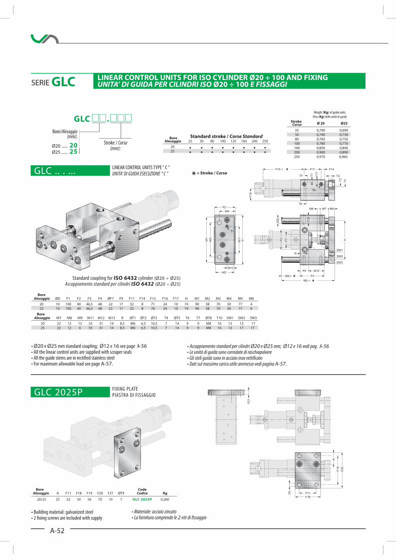
Bore Alesaggio ØD F1 F2 F3 F4 ØF7 F9 F11 F14 F15 F16 F17 H M1 M2 M3 M4 M5 M6
20 10 100 40 46,5 48 22 17 32 8 71 24 10 74 90 38 70 30 77 4
25 10 100 40 46,5 48 22 17 32 8 76 24 10 74 90 38 70 30 77 6
Bore Alesaggio M7 M8 M9 M11 M12 M13 R ØT1 ØT2 ØT3 T4 ØT5 T6 T7 ØT8 T10 SW1 SW2 SW3
20 22 12 12 55 31 14 8,5 M6 6,5 10,5 7 14 9 9 M8 16 13 13 17
25 22 12 6 55 31 14 8,5 M6 6,5 10,5 7 14 9 9 M8 16 13 17 17
* = Stroke / Corsa
GLC .
Bore/Alesaggio(mm):
Ø20 ...... 20Ø25 ...... 25
Stroke / Corsa(mm):
Building material: galvanized steel 2 !xing screws are included with supply
Materiale: acciaio zincatoLa fornitura comprende le 2 viti di !ssaggio
Accoppiamento standard per cilindri Ø20 e Ø25 mm; Ø12 e 16 vedi pag. A-56
Le unità di guida sono corredate di raschiapolvereGli steli guida sono in acciaio inox retti!catoDati sul massimo carico utile ammesso vedi pagina A-57.
Ø20 e Ø25 mm standard coupling; Ø12 e 16 see page A-56
All the linear control units are supplied with scraper seals All the guide stems are in recti!ed stainless steel For maximum allowable load see page A-57.
Bore Code Alesaggio A F11 F18 F19 F20 F21 ØT9 Codice Kg
20/25 25 32 50 56 70 10 7 GLC 2025P 0,260
Stroke Corsa Ø 20 Ø25
25 0,700 0,690
50 0,740 0,730
80 0,760 0,750
100 0,780 0,770
160 0,850 0,840
200 0,900 0,890
250 0,970 0,960
SERIE GLC GNIXIF DNA 001 ÷ 02Ø REDNILYC OSI ROF STINU LORTNOC RAENILUNITA’ DI GUIDA PER CILINDRI ISO 001 ÷ 02Ø E FISSAGGI
Standard coupling for ISO 6432 cylinder (Ø20 ÷ Ø25)
Accoppiamento standard per cilindri ISO 6432 (Ø20 ÷ Ø25)
/ ekorts dradnatS Corse Standard Alesaggio 25 50 80 100 125 160 200 250
20 25
Bore
Weight (Kg) of guide units
Peso (Kg) delle unità di guida
GLC .. . ...LINEAR CONTROL UNITS TYPE “ C ”UNITA’ DI GUIDA ESECUZIONE “ C ”
GLC 2025PFIXING PLATE PIASTRA DI FISSAGGIO
A-53
CIL
IND
RI
PN
EU
MA
TIC
I
PN
EU
MA
TIC
CY
LIN
DE
RS
GLC .
Bore / Alesaggio(mm):
Ø32 ..... 32Ø40 ..... 40Ø50 ..... 50Ø63 ..... 63Ø80 ..... 80
Ø100 ... 100
Stroke / Corsa(mm):
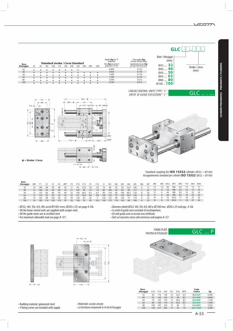
Bore Alesaggio ØD F1 F2 F3 F4 ØF7 F9 F10 F12 F5 F14 H M1 M2 M3 M4 M5 M6 M7
32 10 100 48 58 48 30 17 94 32,5 7,8 7,8 74 90 45 78 32,5 106 6 17
40 12 106 56 64 58 35 21 105 38 10 10 80 100 50 84 38 117 7 22
50 12 125 66 80 59 40 25 106 46,5 6,3 6,3 96 120 60 100 46,5 129 8 26
63 12 132 76 95 76 45 25 121 56,5 9,8 9,8 104 125 70 105 56,5 146 8 26
80 16 165 98 130 90 45 34 128 50 20 9 130 155 90 130 72 170 9 33
100 16 185 118 150 110 55 39 138 70 20 10,5 150 175 110 150 89 190 9 33
M8 M9 M12 ØT1 ØT2 T10 SW1 SW2
12 13 45 M6 6,5 12 15 17
12 6 53 M6 6,5 12 15 19
15 6 64 M8 8,5 16 22 24
15 6 64 M8 8,5 16 22 24
16 8 72 M10 11 18 27 30
16 8 72 M10 11 18 27 30
Bore Code Alesaggio F18 F19 F20 F21 F22 ØT9 Codice Kg
32 50 116 130 10 32,5 6,5 GLC32P 0,500
40 55 126 142 10 38 8,5 GLC40P 0,600
50 70 150 170 12 46,5 8,5 GLC50P 1,100
63 80 156 176 12 56,5 8,5 GLC63P 1,300
80 100 195 220 15 80 12 GLC80P 2,550
100 120 217 245 15 95 14 GLC100P 3,390
* = Stroke / Corsa
Building material: galvanized steel 4 !xing screws are included with supply
Materiale: acciaio zincatoLa fornitura comprende le 4 viti di !ssaggio
Diametro cilindri Ø32; 40; 50; 63; 80 e Ø100 mm; Ø20 e 25 vedi pag. A-56.Le unità di guida sono corredate di raschiapolvere.Gli steli guida sono in acciaio inox retti!catoDati sul massimo carico utile ammesso vedi pagina A-57.
Ø32; 40; 50; 63; 80 and Ø100 mm; Ø20 e 25 see page A-56. All the linear control units are supplied with scraper seals. All the guide stems are in recti!ed steel For maximum allowable load see page A-57.
Standard coupling for ISO 15552 cylinder (Ø32 ÷ Ø100)
Accoppiamento standard per cilindri ISO 15552 (Ø32 ÷ Ø100)
/ ekorts dradnatS Corse Standard Alesaggio 25 50 80 100 125 160 200 250 300 400 500
32 40 50 63 80 100
Bore
Weight (Kg) for “0” Extra weight (Kg) stroke unit for each 100 mm stroke
Peso (Kg) per unità di Supplemento di peso (Kg) guida corsa “0” mm per ogni 100 mm di corsa
0,660 0,122
0,960 0,176
1,400 0,176
1,700 0,176
3,500 0,312
4,700 0,312
GLC .. . ... LINEAR CONTROL UNITS TYPE “ C “
UNITA’ DI GUIDA ESECUZIONE “ C “
GLC ... PFIXING PLATE
PIASTRA DI FISSAGGIO

A-54
Bore Alesaggio ØD H R P F1 F2 F3 F4 F5 F6 ØF7 F8 F9 F10 F11 M1 M2 M3 M4
20 10 58 8,5 6 79 34 38 108 15 37 22 58 17 71 32,5 76 32 68 20
25 10 58 8,5 1 79 34 38 108 15 37 22 58 17 76 32,5 76 32 68 20
Bore Alesaggio M5 M6 M7 M8 M9 M10 M11 ØT1 ØT2 ØT3 T4 ØT5 ØT6 T7 ØT10 SW1 SW2 SW3
20 160 5 22 12 37 65 40 M6 5,5 9 5,5 10,5 6,5 7 M5 13 13 27
25 160 6 17 12 37 65 40 M6 5,5 9 5,5 10,5 6,5 7 M5 13 17 27
F20
F19
T9
F18
F11 B
F21
Bore Code Alesaggio B F11 F18 F19 F20 F21 ØT9 Codice Kg
20/25 50 32,5 50 50 64 10 6,5 GLH 2025P 0,270
* = Stroke / Corsa
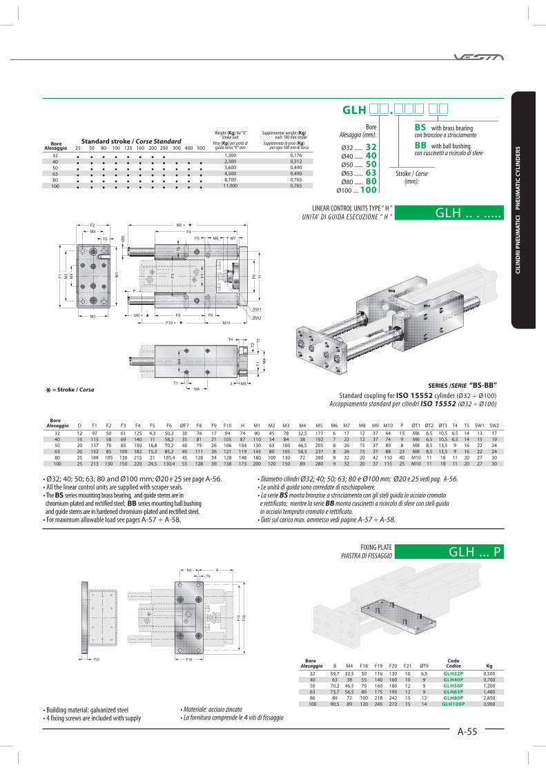
Materiale: acciaio zincatoLa fornitura comprende le 4 viti di fissaggio
GLH .
Alesaggio (mm)
Ø20 ...... 20Ø25 ...... 25
Corse (mm):
BScon bronzine a strisciamento
BB con cuscinetti a ricircolo di sfere
Kg Kg) BS BB
Stroke Peso (Kg) Peso (Kg) Corsa serie “BS” serie “BB”
25 0,815 0,800
50 0,846 0,830
80 0,882 0,870
100 0,907 0,890
160 0,980 0,965
200 1,030 1,015
250 1,090 1,075
Accoppiamento standard per cilindri Ø20 e Ø25 mm; Ø12 e 16 vedi pag. A-56.Le unità di guida sono corredate di raschiapolvere.La serie BS monta bronzine a strisciamento con gli steli guida in acciaio cromato
e rettificato; mentre la serie BB monta cuscinetti a ricircolo di sfere con steli guida in acciaio temprato cromato e rettificato.
Dati sul carico max. ammesso vedi pagine A-57 ÷ A-58.
SERIE GLH LINEAR CONTROL UNITS FOR ISO CYLINDER Ø20 ÷ 100 AND FIXINGUNITA’ DI GUIDA PER CILINDRI ISO Ø20 ÷ 100 E FISSAGGI
SERIES /SERIE “BS-BB”
ISO 6432 (Ø20 ÷ Ø25)
Accoppiamento standard per cilindri ISO 6432 (Ø20 ÷ Ø25)
Ø20 Ø25 Ø12 16 56.
BS BB
A-57 ÷ A-58.
Standard stroke / Corse Standard Alesaggio 25 50 80 100 125 160 200 250
20
25
Bore
Kg Ø20 Ø25
Peso (Kg) delle unità di guida Ø20 e Ø25
GLH .. . ... UNITA’ DI GUIDA ESECUZIONE “ H ”
GLH 2025P PIASTRA DI FISSAGGIO
A-55
CIL
IND
RI
PN
EU
MA
TIC
I
PN
EU
MA
TIC
CY
LIN
DE
RS
Bore Code Alesaggio B M4 F18 F19 F20 F21 ØT9 Codice Kg
32 59,7 32,5 50 116 130 10 6,5 GLH32P 0,500
40 63 38 55 140 160 10 9 GLH40P 0,700
50 70,2 46,5 70 160 180 12 9 GLH50P 1,200
63 73,7 56,5 80 175 195 12 9 GLH63P 1,480
80 89 72 100 218 242 15 12 GLH80P 2,850
100 90,5 89 120 245 272 15 14 GLH100P 3,900
Bore Alesaggio D F1 F2 F3 F4 F5 F6 ØF7 F8 F9 F10 H M1 M2 M3 M4 M5 M6 M7
32 12 97 50 61 125 4,3 50,2 30 76 17 94 74 90 45 78 32,5 177 6 17
40 16 115 58 69 140 11 58,2 35 81 21 105 87 110 54 84 38 192 7 22
50 20 137 70 85 150 18,8 70,2 40 79 26 106 104 130 63 100 46,5 205 8 26
63 20 152 85 100 182 15,3 85,2 45 111 26 121 119 145 80 105 56,5 237 8 26
80 25 189 105 130 215 21 105,4 45 128 34 128 148 180 100 130 72 280 9 32
100 25 213 130 150 220 24,5 130,4 55 128 39 138 173 200 120 150 89 280 9 32
M8 M9 M10 P ØT1 ØT2 ØT3 T4 T5 SW1 SW2
12 37 64 15 M6 6,5 10,5 6,5 14 13 17
12 37 74 9 M6 6,5 10,5 6,5 14 15 19
15 37 89 8 M8 8,5 13,5 9 16 22 24
15 37 88 23 M8 8,5 13,5 9 16 22 24
20 42 110 40 M10 11 18 11 20 27 30
20 37 115 25 M10 11 18 11 20 27 30
* = Stroke / Corsa
Diametro cilindri Ø32; 40; 50; 63; 80 e Ø100 mm; Ø20 e 25 vedi pag. A-56.Le unità di guida sono corredate di raschiapolvere.La serie BS monta bronzine a strisciamento con gli steli guida in acciaio cromato
e rettificato; mentre la serie BB monta cuscinetti a ricircolo di sfere con steli guida in acciaio temprato cromato e rettificato.
Dati sul carico max. ammesso vedi pagine A-57 ÷ A-58.
Ø32; 40; 50; 63; 80 and Ø100 mm; Ø20 25 A-56.
BS BB
A-57 ÷ A-58.
Materiale: acciaio zincatoLa fornitura comprende le 4 viti di fissaggio
SERIES /SERIE “BS-BB”
ISO 15552 (Ø32 ÷ Ø100)
Accoppiamento standard per cilindri ISO 15552 (Ø32 ÷ Ø100)
Standard stroke / Corse Standard Alesaggio 25 50 80 100 125 160 200 250 300 400 500
32
40
50
63
80
100
Bore
Kg Kg)
Peso (Kg) per unità di Supplemento di peso (Kg) guida corsa “0” mm per ogni 100 mm di corsa
1,300 0,176
2,300 0,312
3,600 0,490
4,500 0,490
8,700 0,765
11,000 0,765
GLH .
Alesaggio (mm)
Ø32 ...... 32Ø40 ...... 40Ø50 ...... 50Ø63 ...... 63Ø80 ...... 80
Ø100 .... 100
Corse (mm):
BScon bronzine a strisciamento
BB con cuscinetti a ricircolo di sfere
GLH .. . .....UNITA’ DI GUIDA ESECUZIONE “ H ”
GLH ... P PIASTRA DI FISSAGGIO

A-56
COMBINATION OF ASSEMBLING / COMBINAZIONI DI ASSEMBLAGGIO
Bore Code Alesaggio A B C D E F G H Codice Kg
20 / 25 78 12 22 58 16,5 37,5 13,5 54 RFGLH20/25 0,110
32 95 15 22 74 25 47 22 70 RFGLH32 0,170
40 113 20 17 87 29 54 25 80 RFGLH40 0,310
50 134 20 17 104 35 67,5 32,5 100 RFGLH50 0,460
63 149 20 17 119 42,5 80,5 38 120 RFGLH63 0,600
80 185 25 12 148 52,5 101,5 49 150 RFGLH80 1,150
100 209 25 12 173 65 116 51 165 RFGLH100 1,350
Linear control Adaption set units - size Set di adattamento Guide laterali taglia Ø20 Ø25 Ø32 Ø40 Ø50 Ø63 Ø80 Ø100
RF32/20 RF32/25 GLH32 N20/32 N25/32
RF40/20 RF40/25 GLC-GLH40 N20/40 N25/40
RF50/32 GLC-GLH50 N32/50
RF63/32 RF63/40 GLC-GLH63 N32/63 N40/63
RF80/40 RF80/50 GLC-GLH80 N40/80 N50/80
RF100/50 RF100/63 GLC-GLH100 N50/100 N63/100
Available on demand (with modification linear control units) / Fornibile a richiesta (con modifica su guida laterale)
Standard coupling / Accoppiamento standard
Standard coupling / Accoppiamento standard
Linear control Adaption set units - size Set di adattamento Guide laterali taglia Ø12 Ø16 Ø20 Ø25
RF25/12 RF25/16 GLH20/25 N12/25 N16/25
RF32/20 RF32/25 GLH32 N20/32 N25/32
RF25/12 RF25/16 GLC20/25 NC12/25 NC16/25
RF32/20 RF32/25 GLC32 NC20/32 NC25/32
RF. . / . .N . . / . .
RF. . / . .N . . / . .
RF. . / . .N . . / . .
RF. . / . .N . . / . .
Adaption set to assemble ISO 6432 cylinders
(with threaded flange mounting) on GLC and GLH linear control units series.
Adattatori per l’assemblaggio dei cilindri ISO 6432
(con fissaggio a flangia filettata) su guide GLC e GLH
Adaption set to assemble ISO 15552 and ISO 6432 cylinders
(with 4 screw fixing) on GLC and GLH linear control units series.
Adattatori per l’assemblaggio dei cilindri ISO 15552 e ISO 6432.
(con fissaggio a 4 viti filettate) su guide GLC e GLH
* = Stroke / Corsa
Materiale: lega di alluminio2 viti di bloccaggio
RFGLH ..REAR FLANGE COUPLING GUIDE STEMS

A-57
CIL
IND
RI
PN
EU
MA
TIC
I
PN
EU
MA
TIC
CY
LIN
DE
RS
INFLECTION GRAPHICS AND MAXIMUM ALLOWABLE LOADDIAGRAMMI DI INFLESSIONE E MASSIMO CARICO UTILE
Ø20÷100 GLC
Ø20÷100 GLH BB-BS
Ø20÷100 GLH BS
Maximum allowable load (N), with the longitudinal axes of the unit horizontal placed. The graphic on the right has been executed with the load placed as figure.
Massimo carico utile (N) con asse longitudinale dell’unità di guida disposto orizzontalmente. Il grafico a destra é stato eseguito con il baricentro del carico disposto come figura.
Inflection of guide stems is due to their weight summed to the load of 10 N related to the stroke. The BS series mounting brass bearing, and guide stems are in chromium-plated and rectified steel; BB series mounting ball bushing and guide stems are in hardened chromium-plated and rectified steel. The graphic on the right has been executed with the load placed as figure.
Inflessione degli steli dovuta al peso proprio sommato ad un carico di 10 N in relazione alla corsa. La serie BS monta bronzine a strisciamento con gli steli guida in acciaio cromato e rettificato; mentre la serie BB monta cuscinetti a ricircolo di sfere con steli guida in acciaio temprato cromato e rettificato. Il grafico a destra é stato eseguito con il baricentro del carico disposto come figura.
Maximum allowable load (N), with the longitudinal axes of the unit horizontal placed. BS series mounting brass bearing and guide stems in chromium-plated and rectified steel.The graphic on the right has been executed with the load placed as figure.
Massimo carico utile (N) con asse longitudinale dell’unità di guida disposto orizzontalmente. La serie BS monta bronzine a strisciamento e steli guida in acciaio cromato rettificato. Il grafico a destra é stato eseguito con il baricentro del carico disposto come figura.
MAX. ALLOWABLE LOAD “N” (Ø20÷100 GLC)MASSIMO CARICO UTILE “N” (Ø20÷100 GLC)
MAX. ALLOWABLE LOAD (Ø20÷100 GLC)MASSIMO CARICO UTILE (Ø20÷100 GLH BS)
INFLECTION OF GUIDE STEMS (Ø20÷100 GLH BS E BB)INFLESSIONE DEGLI STELI (Ø20÷100 GLH BS E BB)
Barycentre of load
Baricentro del carico
Barycentre of load
Baricentro del carico
Barycentre of load
Baricentro del carico
Stroke (mm) / Corsa (mm)
Stroke (mm) / Corsa (mm)
In
fle
ctio
n (
mm
) /
Infl
ess
ion
e (
mm
)
Stroke (mm) / Corsa (mm)
Ma
x.
all
ow
ab
le l
oa
d L
(N
)M
ass
imo
ca
rico
am
mis
sib
ile
L (
N)
Ma
x.
all
ow
ab
le l
oa
d L
(N
)M
ass
imo
ca
rico
am
mis
sib
ile
L (
N)
* = Stroke / Corsa
* = Stroke / Corsa
* = Stroke / Corsa

A-58
1000 200 300 400 500 600
Ø 80-100
Ø 50-63
Ø 40
Ø 32
Ø 20-25
50
100
150
200
250
300
350
400
450
500
550
20÷100 GLH BB
Reduction of allowable load with short stroke. For stroke <60 mm multiply the allowable load per”K”.
Riduzione del carico utile con corsa breve.Per corse <60 mm moltiplicare il carico ammesso per “K”.
Stroke Corsa K
50 0,9
40 0,8
30 0,7
20 0,6
Maximum allowable load (N), with the longitudinal axes of the unit horizontal placed. BB series mounting brass bearing and guide stems in hardened chromium-plated and rectified steel. The graphic on the right has beenexecuted with the load placed as figure.
Massimo carico utile (N) con asse longitudinale dell’unità di guida disposto orizzontalmente. La serie BB monta bronzine a strisciamento e steli guida in acciaio temprato cromato e rettificato. Il grafico a destra é stato eseguito con il baricentro del carico disposto come figura.
MAX. ALLOWABLE LOAD FOR A LIFE-TIME OF 250 KmCARICO MASSIMO PER DURATA DI CIRCA 250 Km
Barycentre of load
Baricentro del carico
Ma
x.
all
ow
ab
le l
oa
d L
(N
) -f
or
a l
ife
tim
e a
bo
ut
60
0 K
mM
ass
imo
ca
rico
L (
N)
- p
er
du
rata
di
circ
a 6
00
Km
Stroke (mm) / Corsa (mm)
Ma
x.
all
ow
ab
le l
oa
d L
(N
) fo
r a
lif
e t
ime
ab
ou
t 2
50
Km
M
ass
imo
ca
rico
L (
N)
pe
r d
ura
ta d
i ci
rca
25
0 K
m
Stroke (mm) / Corsa (mm)
* = Stroke / Corsa
MAX. ALLOWABLE LOAD FOR A LIFE-TIME OF 600 KmCARICO MASSIMO PER DURATA DI CIRCA 600 Km