GLASS PICKET CABLE - CrystaLite, Inc.files.crystaliteinc.com/railing/INSTALL_railing.pdf · ·...
28
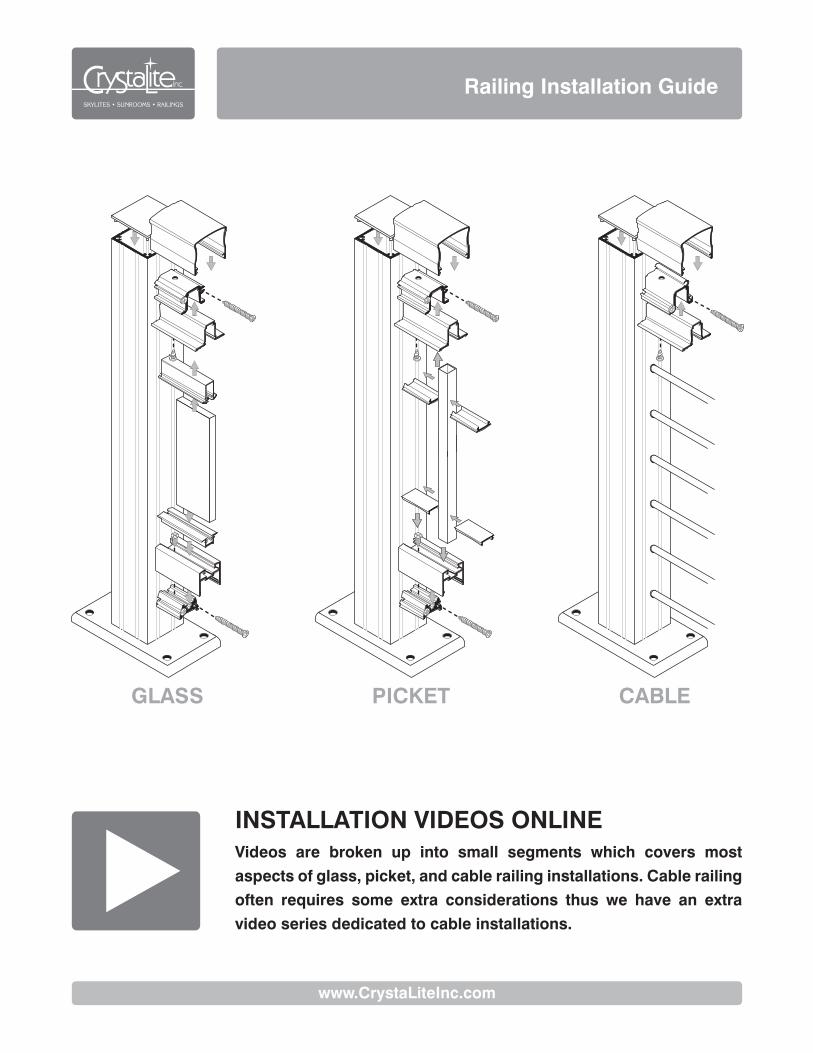
Railing Installation Guide GLASS PICKET CABLE INSTALLATION VIDEOS ONLINE Videos are broken up into small segments which covers most aspects of glass, picket, and cable railing installations. Cable railing often requires some extra considerations thus we have an extra video series dedicated to cable installations. www.CrystaLiteInc.com
-
Upload
phungnguyet -
Category
Documents
-
view
217 -
download
0
Transcript of GLASS PICKET CABLE - CrystaLite, Inc.files.crystaliteinc.com/railing/INSTALL_railing.pdf · ·...
Railing Installation Guide
GLASS PICKET CABLE
INSTALLATION VIDEOS ONLINEVideos are broken up into small segments which covers most
aspects of glass, picket, and cable railing installations. Cable railing
often requires some extra considerations thus we have an extra
video series dedicated to cable installations.
www.CrystaLiteInc.com

1 CrystaLite, Inc. Railing Installation Guide
Introduction
The CrystaLite Railing Systems engineered design was developed to meet all existing local building codes. It is necessary to follow the post layout provided and the methods for properly anchoring the system.
The design assumes that the materials on the building site are of sufficient condition and strength to adequately support the railing and appropriately anchor the railing to accommodate the applied loads. It is necessary that the installer observes site conditions and determine the condition of the materials provided by others.
The design assumes that sound building practices were observed during the construction of the mounting surface and was constructed to be true and level in accordance with standard building practices. Any variances or abnormal conditions should be reported to CrystaLite.
The CrystaLite Railing System is a very flexible and sophisticated design. It is necessary to have more than a limited knowledge of the system. CrystaLite offers free training for your convenience in order to provide the maximum opportunity for a sound installation. It is highly recommended that you capitalize on this opportunity to learn the system from those who have years of experience and many installations to back up that experience.
This installation guideline is meant to provide the general basics and common conditions encountered in the field. Since it is not possible to address every conceivable condition that may exist, it is understandable that there may be potential installations not included in this install guide.
Installation Overview
The following lists the order of steps required for a railing installation.
1. Posts are placed into location, but are NOT fastened to the deck. The railing system will be constructed in place, but without being fastened to the deck until nearly complete.
a. Except for side mount applications and cable rail projects without bottom rail; posts will need to be located and fastened.
2. Bottom Rails are measured, cut and installed. 3. Snap Pockets (used to hold the Top Rail) are measured, cut and installed.
a. NOTE: Some Cable Installations require this step to be done later. 4. The railing system is now fastened to the deck. 5. Top Rails are measured, cut and installed.
a. NOTE: Some Cable Installations require this step to be done later. b. NOTE: The difference in procedure for each corner scenario.
6. Installation of the infill area. a. For cable railing and picket, these will now be installed. b. For glass infill systems, final glass sizes will now be measured and sent to CrystaLite for fabrication.
The installation of glass will continue when glass is received.

Railing Installation Guide CrystaLite, Inc. 2
Required Tools
• 10” or larger Miter Chop Saw with non-ferrous metal cutting blade (80-100 tooth)
• 3/8" Electric Drill (cordless recommended) • 3/16” Drill Bit - preferably 6" long • 1/4” Drill Bit - preferably 6" long • Cordless Impact Wrench (recommended) • #3 Square Drive Bit - preferably 6” long • #2 Philips Drive Bit - preferably 6” long • #2 Philips Head Screwdriver • 7/16” Wrench • 6” File - Half Round Fine or 2nd Cut • Vice Grip Pliers • Quick Grip' clamps - 10" wide gripping capacity
needed for stair installation • Ear and Eye Protection • Pencils • Short Level - 2 feet or less • Chalk Line or String • Tape Measure • Wax - lubricant for screws and saw blade • Cable Cutters • Concrete or Masonry Installs will require Special
Tools and Fasteners
Recommended Tools
• Speed Square • Rubber Mallet and/or Dead Blow Hammer • CrystaLite Drill Jig - useful in field fabricating
from stock lengths • Top Rail Installation Clamps - required for 9001
System installation • Glass Vacuum Cups - for glass installation • Drill Index - other Drill sizes may be needed in
some applications • 15/64” Transfer Punch • Transit or Water Level
Site Review
Irregularities in the mounting surface may exist. Inspect the deck for high and low spots. This condition may result in the railing not being level and true. If excessive differences exist, which cannot be corrected by shimming the posts, it may be necessary to cut special posts to produce a level railing. For example, to accommodate for a rise in the mounting surface – the post could be trimmed from the bottom and reattached to the base plate.
Parts Manifest
Unpack materials and check parts, using the Parts Manifest included. Report any discrepancies to the dealer or supplier. Most Deck Mount Posts will arrive with the Base Plates and Shear Blocks attached.
Considerations
Cut all parts with the chop saw; do not use hack saws for finish or visible cuts. All screws require a pilot hole as they will not self tap. Pre-drill all aluminum construction holes with a 3/16" bit. Pre-drill holes in decking, floor joists, and blocking to required diameter and depth in accordance with the fastener being used. All screws or fasteners anchoring posts to a deck or mounting surface must be embedded into rim joist, floor joist, blocking, or subsurface to the required depth.

3 CrystaLite, Inc. Railing Installation Guide
Standard Rail Installation
It is inconceivable for this installation guide to address every condition that may exist. This installation guideline is meant to provide the general basics and common conditions encountered in the field. We will begin with discussing Deck Mounted Posts as our foundation guidelines. Stairs and Side Mount posts will also be discussed.
The following outlines the steps required for our standard ‘traditional’ configuration. It utilizes our smaller top rails to pass over our intermediate posts and butt to the sides of larger end posts. Installations done in this manner have far fewer cuts required and allows for the most flexibility.

Railing Installation Guide CrystaLite, Inc. 4
Deck Mount
If there are stairs involved in the deck layout, it may be necessary to start the layout at the stair Newel Post. In any event, the installer should be aware of the position of the Newel Post at the top of the stair. In many cases an auxiliary hand rail (grab rail) may be required as well.

5 CrystaLite, Inc. Railing Installation Guide
1. Post Layout
Refer to the layout provided with your manifest. Place your posts in the approximate position on your deck.
2. End Posts
Your End Posts could be any post, but are typically either the 2.5” wide (9006) or 3.5” wide (9060) post size depending on your Top Rail and configuration choice. Carefully set and align all End Posts into location. Be sure the placement and alignment of the End Posts will ensure that the screw holes are adequately located over the mounting blocking. A minimum of 4” wood blocking must be used below the deck where screw holes are not over an existing joist.
Note: The base plate may be rotated 90 degrees when there is a requirement for abnormally high loading for wind speeds above 100 mph. Longer or larger fasteners may be required.
3. Spacing Intermediate Posts
To determine the spacing of Intermediate Posts, you will measure the inside distance between the End Posts and subtract the thickness of EACH Intermediate Post in that run. For example, you must subtract either 1-3/4” (9005) or 2-1/2” (9006) for each Intermediate Post in the run. Then divide this length by the number of openings between rails. This number is now the distance between each post and the length of each Bottom Rail for this section of railing.

Railing Installation Guide CrystaLite, Inc. 6
4. Cut the Bottom Rails
Most Cable Railings do not include bottom rails as part of the design
The Bottom Rails come with the ends painted from production. Trim off the ends to ensure a true right angle. Cut the Bottom Rails to the length determined in the step above. Cut the rail with the bottom edge against the miter saws back fence to prevent any burrs from being visible.
5. Install Bottom Rails
#12 x 3/4" Fasteners
Snap the Bottom Rails into place on the preinstalled Shear Blocks. Drill 3/16" holes from the top of the Bottom Rail into the Shear Blocks. Drill at a slight angle to ensure no gaps will be left when screwed down. Use #12 x 3/4" Fasteners provided. Drill weep holes 6” from each end as well as the center, from the top down through the channel.
CRITICAL NOTE: After railing installation but before installation of the infill (glass, cable, picket), remove one #12 x 3/4" from each Bottom Rail section to allow for expansion and contraction.
Safety Note: Be sure the part is supported by the saw’s fence on both sides of the blade.
6. Snap Pocket
Measure the total length between the two End Posts. Trim off the painted end from the Snap Pocket, then cut to length. Slide the Snap Pocket into place; the Pocket sits on top of the Intermediate Posts and mounts on the underside of the upper Shear Blocks. Allow at least 1” overhang where end caps will be used if not terminating the run at an End Post.
NOTE: See additional procedures if the run includes a corner where the Top Rail runs ‘Over-the-Top.’
7. Drill and Screw Snap Pocket
#12 x 1/2" Fasteners
Drill 3/16" holes from the underside of the Shear Block up through the Snap Pocket; drill at an angle towards the End Post. Insert screws from the underside of the Shear Block up through the Snap Pocket to ensure the screw does not come into conflict with the rest of the assembly.
8. Pocket to Intermediate Posts
#12 x 1" Fasteners
Ensure that the Intermediate Posts are true by measuring and/or with a level. Using the grooved line in the Snap Pocket on each side; drill and screw 4 screws from the top of the Snap Pocket into the top of the Intermediate Posts.

7 CrystaLite, Inc. Railing Installation Guide
9. Screw Posts into Place
Minimum 1/4” dia. Fasteners
Now is the time to fasten the Posts to the deck. Recheck your alignment for your End Posts and screw these down first. Locate and pre-drill mounting holes, ensuring the posts are plumb when tightening. Ensure that the Intermediate Posts are straight; wrap a string-line around the outside of your End Posts and use this line as your reference line to measure from. Drill and screw these posts in place. Remember; all screws must be installed into a joist or other form of blocking.
10. Cut Top Rail
Measure the span between the two End Posts following the Snap Pocket. Trim off the painted edge on the Top Rail then cut to fit. To keep the Top Rail true to shape and to make a clean cut; place a small scrap of Snap Pocket inside the Top Rail just behind your cut line. This is especially important for mitered corners.
NOTE: See Corner Posts procedures if the run includes a corner.
Safety Note: Be sure the part is supported by the saw’s fence on both sides of the blade.
11. Snap on Top Rail
Unscrew one of the ½” screws used in the installation of the Snap Pocket. This will give you some play while snapping in the Top Rail and keep you from scratching the post. Gently snap the Top Rail over the Snap Pocket. A set of clamps may be helpful to use to assist with this step. Reinstall the screw you removed.
12. Post Caps
Press in the Post Caps onto the tops of the End Posts. Tap in with a non-marking rubber mallet or dead blow hammer.

Railing Installation Guide CrystaLite, Inc. 8
Side Mount Installation
Side Mount Installation is almost identical to Deck Mount Installation but does have a few extra challenges. For the purposes of this guide; we will assume that you have gone through the Deck Mount procedures and that the deck is level or the railing will be perpendicular to the deck surface.
1. Preparation
For residential railings, the Top Rail must be at least 36" from the deck; 42” for commercial. With this in mind, measure and mark a line on your End Posts where the edge of the deck will be. Some Side Mount installs will require two Corner Posts, one on each face of the deck. Be sure in your post layout that gap between two Corner Posts is less than 4 inches.
2. Spacers
If Spacers are needed, begin by measuring the length of deck surface that over hangs from the joist. Do not cut all at once. You may need to adjust for irregularities in the structure of the deck. If Intermediate Posts are smaller than End Posts, Spacer are needed to center the Intermediate Posts to the End Posts.

9 CrystaLite, Inc. Railing Installation Guide
3. Starting End Post
Minimum 1/4” dia. Fasteners
Align the first End Post on the side of the deck. Use the mark you created to set the height. Install the upper mounting screw from the outside of the End Post into the joist with the first Spacer in place. Be sure the post is level and the first screw is snug. Measure the distance from the joist to the bottom of the post. Use this measurement to cut and install the second Spacer for this post.
Repeat Steps 2 & 3 for the remainder of posts required in the installation. Then refer back to Deck Mount Installation for further instructions.
End Caps
1. Snap Pocket
End Caps are placed on the ends of Top Rails for installations that run ‘Over the Top’ of the Posts. It is easiest to install the End Cap to the Snap Pocket before mounting the Snap Pocket to the End Post.
2. Snap Pocket
Measure and cut the Snap Pocket to desired length. In order to install an End Cap; you must allow for at least a 1" over-hang from the End Post. Cosmetically it is best if the Snap Pocket is sized to extend even with the Base Plate.
3. Drill and Screw
Small Screw and Hex Nut
Remove the machine screw for the inside of the End Cap but leave the nut in the boss still inside. Drill a 3/16" hole 1” from the edge and from underneath the Snap Pocket to allow the machine screw to pass through. Place the End Cap on the end of the Snap Pocket and reinstall screw from the underside of the Snap Pocket back into the End Cap. Tighten screw firmly.

Railing Installation Guide CrystaLite, Inc. 10
90˚ Corner Posts – Over the Top Some configurations may have a 90 degree turn in a railing which is not made using an End Post.
1. Sizing the Snap Pocket
Refer to Appendix A for 135˚ Corner Posts.
Measure from the last End Post to the corner 1/8" past the last adjacent post in the railing section you wish to join. Cut the Snap Pocket to that length with a 45 degree cut on the corner end. Place this piece in place.
Now measure from the inside edge of the other End Post to the outside edge of the Snap Pocket you just placed. Cut the second piece of Snap Pocket to this size, with a 45 degree angle in the other direction at the corner. Place this piece in place.
2. Install the Snap Pocket
#12 x 1/2" Fasteners, (2) Aluminum Straps
Clamp the ends of the Snap Pocket together at the corner. Now you can drill and screw the Snap Pocket into the Corner Posts while maintaining a flush corner. Drill and screw a piece of 90 degree Aluminum Strap to the outside edge of the Snap Pocket. Remove the clamps. Do the same for the inside edge.
3. Sizing the Top Rail
To measure the length required for the final piece, cut two pieces of Top Rail approximately 8" long with opposite 45 degree cuts. Remember, when cutting Top Rail; place a small scrap of Snap Pocket near where you intend to cut to keep the Top Rail in its true shape to make a clean cut. Tap these two pieces into place at the corner and check for fit. Slide one piece back from the corner. Now measure from the end of the Top Rail piece still in place to the edge of the last End Post or Top Rail. Cut your Top Rail to this length. Do the same for the other side.
4. Install the Top Rail
Remove one of the screws from the Snap Pocket to the Shear Block. This will give you some play for installing the Top Rail. Snap the Top Rail onto the Snap Pocket. Reinstall the screw from below the Snap Pocket back into the Shear Block.

11 CrystaLite, Inc. Railing Installation Guide
Stair Installation
Stair Installation of a CrystaLite Railing System is a little different than when installing on a flat surface. Most cuts made to the Railing System will be at an angle. Once this angle has been established; the process is similar to the flat or Deck Mount procedures. It is recommended that you first get familiar with installing your railing on the flat portion before moving on to stairs. For the purposes of this guide; we will assume that you have gone through the Deck Mount procedures.
1. Newel Post
Place your first End Post at the top of the stair run. This is what is referred to as a Newel Post. Place the other Newel Post on the bottom of the stairs as well. If there is a turn in the stairs; be sure each Newel Post is located in the correct position to continue the Railing System through the turn.
2. Finding the Angle
For Stair Installation; the Bottom Rail is used to find the angle in which the posts will be cut. If your Cable Rail System does not use a Bottom Rail, any straight edge can be substituted for this process.
Lay the uncut Bottom Railing on the steps on the inside of the posts. Place shims under the Bottom Rail to assure clearance and a clean line between the posts. Clamp the rail in place. Mark the angle on the Bottom Rail where it meets the End Post. Mark the End Post where the bottom of the Bottom Rail crosses.

Railing Installation Guide CrystaLite, Inc. 12
3. Rail Height
Measure and mark the intended height of the railing. For residential grab rail requirements, the height must be between 34”-38” (36” +/- 2) vertical from the toe of the stair tread. Commercial installations require a minimum of 42” with addition of an auxiliary hand rail.
4. Using the Angle
Cut the Bottom Railing at the mark and angle you had drawn. Leave your miter saw set to this pitch. It should be the same now for all cuts.
5. Shear Blocks
#12 x 3" Fasteners
Since the exact pitch of stairs is unknown when the Rail System is ordered; the Shear Blocks (Top and Bottom) do not come preinstalled like they are for Deck Mount. Your miter saw should be still set to the pitch you cut the Bottom Rail at. Cut a 5" length of Bottom Shear Block from your 4ft stock provided with this same angle on both ends. Cut this new piece in half at 90 degrees which will yield two Bottom Shear Blocks with the proper angle and length.
Shear Block Stock Cut Pieces
Transfer the lines you traced from the Bottom Rail to the adjacent face of the post. This will give you the location of the Bottom Shear Block.
Cut a small piece of Bottom Rail at the proper angle. Slide this over a Shear Block you just created. Align the combined pieces on the line on the bottom side of the post. Use the transfer punch to mark one of the hole centers from the Shear Block to the post. Use a square to mark the second hole. Drill the marked holes square with the surface of the post; then tilt the drill to pitch. Attach with fasteners. This process will need to be done to both sides of each Intermediate Post.

13 CrystaLite, Inc. Railing Installation Guide
You will need to repeat this process for the Top Rail. To do so, you will need to cut a small piece of Snap Pocket as well as a piece of Top Rail. Clamping all three items with a set of pliers will make it easier to mark your first hole with the transfer punch.
6. Cut Newel Posts to Height
Using the same clamped jig in the previous step, mark the top of the Top Rail location as it butts against the Newel Posts. Cut the Newel Posts to height, 1/4” above your mark.
7. Intermediate Posts
Measure the distance from the bottom of the Bottom Shear Block to the bottom of the Top Shear Block that you installed on the upper End Post. Transfer this measurement to each Intermediate Post. Use this mark to cut the Intermediate Posts to proper height and pitch.
NOTE: Save the excess removed from the Intermediate Posts. It will be useful in later steps.
8. Finishing the Stairs
The remaining steps required to finish the stair installation is nearly the same as is for the standard (flat) installation procedures EXCEPT that the width of the Intermediate Posts is longer due to the angle of the run. This is critical when determining the length of the Bottom Rails and the overall span for the Snap Pocket and Top Rail. The adjusted width of the Intermediate Post can easily be measured with the excess scrap cut from the Intermediate Post in the previous step.
Alternatively, a long straight edge could be used to measure the total run and/or Bottom Rail lengths.
Refer back to the previous procedures for Standard Rail Installation for a step-by-step guide to complete the Stair Installation, keeping in mind the longer width of the Intermediate Posts due to the angle of the run.

Railing Installation Guide CrystaLite, Inc. 14
Glass Installation
1. Measuring for Glass
You will need to provide CrystaLite with a few careful measurements. All measurements will need to be made from the bottom of the Bottom Rail to the bottom of the Top Rail – where they meet the posts. CrystaLite will make the appropriate deductions required using these measurements. Mark your dimensions on the worksheet provided. See the diagram below and take care in noticing the start and end points for the measurements needed.
DECK / FLAT INSTALLATION STAIR / SLOPE INSTALLATION
B
R
TL
BLTR
TLBR
Bottom of Bottom Rail
Bottom of Top Rail
R
BBottom of Bottom Rail
Bottom of Top Rail
2. Vinyl Inserts
You will need to insert the PVC strips into the Bottom Rails and Snap Pockets of your Railing System. You will use the same measurements and angles used in cutting your Bottom Rails to make your inserts. Drill weep holes in PVC as you did for the Bottom Rails as well.
3. Placing in the Glass
Two people are generally needed, rubber fingered gloves is strongly recommended for grip. Use a screw driver or Vinyl Spreader Tool to expand the vinyl inserts and spray with glass cleaner for lubrication. Push one corner of the top edge up into the top PVC insert. Holding the first corner into place, push the other corner up into the PVC insert. Swing the glass over the Bottom Rail. Center the glass between the posts. Once the glass is fully inserted, it cannot be moved. Finally, push the glass down firmly into the bottom vinyl insert; ensure mid span of the Bottom Rail seats fully. Insert glass stops on each side of glass.
2 31
5-1/2 in.4 in.
Top Rail
1-1/2” TopShear Block
Snap Pocket
Top Glazing Vinyl
#12 x 2” SMS
#12 x 1/2” SMS
Glass
Post Cap
#12 x 2” SMS
Bottom Rail
BottomGlazing Vinyl
1-1/2” BottomShear Block

15 CrystaLite, Inc. Railing Installation Guide
Picket Installation
The Pickets are pre-cut to size for standard 36" or 42" high railing systems. For Pickets that must be cut on site, measure from the bottom of the Bottom Rail to the bottom of the Top Rail. Cut your Pickets to this length; cut to pitch if for Stair Installation.
The following steps are required for each opening between posts where Pickets are to be used.
Per building code requirements, the distance between any two Pickets must be less than 4 inches.
1. First Pickets
Starting at one end of your opening, place the first Picket in to the Bottom Rail and Snap Pocket – then push all the way against the face of the End Post. Place a 3-7/8” Spacer into the Bottom Rail and then another Picket. Continue placing Spacers and Pickets until the length of your run until there is a gap less than 7-3/4”.
2. Cutting End Spacers
Measure the remaining gap. Cut a Spacer to half this length. This will give you equal spacing between the Posts and end Pickets while maintaining spaces less than 4” apart from any Picket.
3. Final Alignment
Place the newly cut Spacer in the gap. Slide the rest of the Pickets down to meet flush. Measure the remaining gap at the beginning of the run and cut your last Spacer to size. Install the Spacer at the end of the run.
4. Top Spacers
Finish the Picket installation by inserting the Spacers into the Snap Pocket above. Match the custom cut spacers cut for the bottom.

Railing Installation Guide CrystaLite, Inc. 16
Cable Installation
Most cable railing installations will include at least one corner in which the cable will wrap through the Corner Post without starting and stopping.
However, there are situations when the cable cannot wrap every corner. Recommended alternative configurations are: Double Corner Posts, Staggered Cables and Surface Mount Terminals.

17 CrystaLite, Inc. Railing Installation Guide
1. Build the Railing System
Construct and install the railing system as stated in the above procedures, EXCEPT do not install Post Caps at this time.
NOTE: For installations where the Top Rail will run Over-the-Top of the Corner Posts, do NOT install the Snap Pocket and Top Rail yet.
Note: Once cable is laced and swaged, if it needs to be removed, it will have to be cut.
2. Cable Spreaders
#12 x 1" Fasteners
Cable Spreaders are non-structural elements that are fastened in mid-span to ensure that the cables are not able to be pulled in excess of code requirements. Be sure to include the Cable Spreaders when mounting the other Posts. Fasten to the Snap Pocket and decking surface prior to lacing the cables.
Note: Grommets are NOT used in Cable Spreaders.
3. Drilling For Stairs
All holes required 7/16” drill bit.
To maintain a constant pitch when drilling; measure and drill holes for the cables from both sides of the post. Make all measurements from the bottom of the Top Rail; it is your constant slope to refer to.
If no Grommets are to be used - drill straight into the Post from both sides.
For Grommets are to be used, drill straight into the Post. Grommets will need to have a v-cut to allow the cable to slope up/down without binding on the grommet.

Railing Installation Guide CrystaLite, Inc. 18
Allen WrenchTurn to Tension Cable Pliers / Vice Grips
Hold steady, DO NOT rotate.DO NOT clamp the cable.
Corner Adapter
Threaded Housingwith Washer
½
Quick Lockwith Washer
4. Lace the Cable
Insert the Threaded Terminal into the End Post and just begin to thread into the Threaded Housing (remember the washer), just a turn or two of threads. The remaining threads will be used to tighten the cable run to proper tension later. You cannot lace the cable through the Corner Post with the Corner Wrap Adapter inserted, it will be inserted in the next step.
Be sure to lace the cable through the grommets in-between each Post. Do not yet insert the grommets into the Corner Posts.
Run the cable through the last End Post, but do NOT insert it into the Quick Lock just yet. Once the cable is inserted into the Quick Lock, it cannot be removed.
Note: Grommets are NOT used in Cable Spreader inserts.
5. Corner Wrap Adapter
Push the cables into the Corner Post from both sides to allow a gap to slide in the Corner Wrap Adapter, then insert the Corner Wrap Adapter.
6. Finish the Railing System
For ‘Over-the-Top’ installations or if not already done, install the Snap Pocket and Top Rail as indicated in the previous instructions. Install the Post Caps as well.

19 CrystaLite, Inc. Railing Installation Guide
7. Quick Locks
At this time, slide all grommets into place into the Posts including the Corner Posts. Remove the cable from the last End Post where the Quick Lock is intended to be used. Pull the cable tight as possible by hand with the cable alongside of the End Post. Mark and cut the cable a 1/2” from the outside edge of the post.
Make sure the newly cut cable is wrapped tight and there are no loose strands. Place the Quick-Lock into the post then insert the cable into the Quick-Lock (remember the washer) which will automatically grip and secure the cable. A slight twisting action may help ease the cable in. Remove as much slack as possible.
Holding the Threaded Terminal steady with pliers (do NOT clamp the cable), tighten the Threaded Housing with an Allen wrench to tension each cable as required. DO NOT rotate the cable. Refer to this tension sequence.
NOTE: Wrapping the pliers with tape is recommended to prevent damaging the finish of the Threaded Terminal.
Push the Vinyl Caps on to each fastener, if desired.
11
9
7
5
3
1
2
4
6
8
10

AutoCAD SHX Text
I
AutoCAD SHX Text
n
AutoCAD SHX Text
c
AutoCAD SHX Text
Skylites Sunrooms Railings
AutoCAD SHX Text
Your Clear Choice
AutoCAD SHX Text
Install Guide for 90%%d Cable Adapter
AutoCAD SHX Text
1. Build railing system, install post, snap pocket & top rail.
AutoCAD SHX Text
Instructions for railing systems with top rail butting up to start, stop and corner
AutoCAD SHX Text
posts while going over the top of intermediate posts.
AutoCAD SHX Text
2. Insert threaded terminal through post install TT housing and washer on
AutoCAD SHX Text
terminal a couple of threads just enough to keep nut from falling off.
AutoCAD SHX Text
3. Thread cable with grommets through the posts. DO NOT insert grommets
AutoCAD SHX Text
4. Run the cable through the Quick Lock post, DO NOT put the Quick
AutoCAD SHX Text
Lock on the cable yet.
AutoCAD SHX Text
5. Slide the 9066 or 9067 Corner piece down the screw chase between the
AutoCAD SHX Text
6. Insert grommets into corner post holes.
AutoCAD SHX Text
9006 or 9060 post and cable inside the post.
AutoCAD SHX Text
7. Starting at threaded terminal post pull cable tight working your way to the
AutoCAD SHX Text
Quick Lock post.
AutoCAD SHX Text
8. Pull the cable tight along the outside of the Quick Lock post, with cable
AutoCAD SHX Text
pulled tight, mark and cut the cable 1/2" from edge of post. Make sure
AutoCAD SHX Text
the new cut cable end is wrapped tight, and there are no loose strands
AutoCAD SHX Text
12"
AutoCAD SHX Text
Cut Cable
AutoCAD SHX Text
into the corner post at this time.
AutoCAD SHX Text
9. Insert cable through post and into Quick Lock. SLIGHTLY twisting Quick Lock
AutoCAD SHX Text
and going with the twist of the cable, may help ease cable into the
AutoCAD SHX Text
Quick Lock. Remove as much slack from the cable as possible.
AutoCAD SHX Text
Note: Hold cable on both sides of post, push cable inside
AutoCAD SHX Text
of post to allow 9066 or 9067 to slide down.
AutoCAD SHX Text
11. Finish tightening the cable assemblies from the threaded terminal end.
AutoCAD SHX Text
Rev. Jan. 5, 2018
AutoCAD SHX Text
TOP RAIL
AutoCAD SHX Text
BETWEEN POSTS
AutoCAD SHX Text
out of place.
AutoCAD SHX Text
Quick Lock
AutoCAD SHX Text
Quick Lock

AutoCAD SHX Text
I
AutoCAD SHX Text
n
AutoCAD SHX Text
c
AutoCAD SHX Text
Skylites Sunrooms Railings
AutoCAD SHX Text
Your Clear Choice
AutoCAD SHX Text
Install Guide for 90%%d Cable Adapter
AutoCAD SHX Text
1. Locate and install all posts.
AutoCAD SHX Text
Instructions for railing projects with top rail going over the top of all posts.
AutoCAD SHX Text
2. Insert threaded terminal through post install TT Housing and washer on
AutoCAD SHX Text
terminal a couple of threads just enough to keep nut from falling off.
AutoCAD SHX Text
4. Run the cable through the Quick Lock post, DO NOT put the Quick
AutoCAD SHX Text
Lock on the cable yet.
AutoCAD SHX Text
5. Slide the 9066 or 9067 Corner piece down the screw chase between the
AutoCAD SHX Text
7. Insert grommets into corner post holes.
AutoCAD SHX Text
9006 or 9060 post and cable inside the post.
AutoCAD SHX Text
8. Starting at threaded terminal post, pull cable tight working your way to the
AutoCAD SHX Text
Quick Lock post.
AutoCAD SHX Text
12"
AutoCAD SHX Text
Cut Cable
AutoCAD SHX Text
10. Insert cable through post and into Quick Lock. SLIGHTLY twisting Quick Lock
AutoCAD SHX Text
and going with the twist of the cable, may help ease cable into the
AutoCAD SHX Text
Quick Lock. Remove as much slack from the cable as possible.
AutoCAD SHX Text
Note: Hold cable on both sides of post, push cable inside
AutoCAD SHX Text
of post to allow 9066 or 9067 to slide down.
AutoCAD SHX Text
6. Finish construction of structure, install snap pocket & top rail.
AutoCAD SHX Text
MITERED
AutoCAD SHX Text
TOP RAIL
AutoCAD SHX Text
3. Thread cable with grommets through the posts. DO NOT insert grommets
AutoCAD SHX Text
into the corner post at this time.
AutoCAD SHX Text
9. Pull the cable tight along the outside of the Quick Lock post, with cable
AutoCAD SHX Text
pulled tight, mark and cut the cable 1/2" from edge of post. Make sure
AutoCAD SHX Text
the new cut cable end is wrapped tight, and there are no loose strands
AutoCAD SHX Text
out of place.
AutoCAD SHX Text
12. Finish tightening the cable assemblies from the threaded terminal end.
AutoCAD SHX Text
Rev. Jan. 5, 2018
AutoCAD SHX Text
Quick Lock
AutoCAD SHX Text
Quick Lock

AutoCAD SHX Text
***PLEASE READ: VERY IMPORTANT INSTRUCTIONS***
AutoCAD SHX Text
FAILURE TO USE THE PROPER TOOL AND NOT FOLLOW THESE
AutoCAD SHX Text
INSTRUCTIONS VOIDS ANY WARRANTY!
AutoCAD SHX Text
PERSONAL INJURY CAN RESULT FROM USE OF IMPROPER TOOLS.
AutoCAD SHX Text
CrystaLite, Inc. Hand Swage Fittings Installation Instructions for CrystaLite Hand Swage Tool.
AutoCAD SHX Text
FAILURE WILL RESULT IF YOU DO NOT USE THE PROPER TOOLS
AutoCAD SHX Text
These tools are required for the hand swage fitting installation.
AutoCAD SHX Text
1) CABLE CUTTER
AutoCAD SHX Text
2) CRYSTALITE SWAGE TOOL
AutoCAD SHX Text
3) MARKING PEN
AutoCAD SHX Text
IMPORTANT: Use only Crystalite 1/8" performed,
AutoCAD SHX Text
USE FRONT DIE LOCATION FOR SINGLE SLEEVE APPLICATION
AutoCAD SHX Text
USE REAR DIE LOCATION FOR DOUBLE SLEEVE APPLICATION
AutoCAD SHX Text
2) With machined swage end anchored at other end, lead cable through the supports.
AutoCAD SHX Text
4) Place the terminal into the proper die on the tool.
AutoCAD SHX Text
1/8" cable with the a single sleeve or
AutoCAD SHX Text
1/8" cable with the a double sleeve (use the rear die location)
AutoCAD SHX Text
Be sure to use both sleeves if assembly supplies two.
AutoCAD SHX Text
3) While holding the cable taut mark and cut to length as shown in A and B diagrams.
AutoCAD SHX Text
5) Complete two crimps as shown in A and B diagrams, based on which terminal is being used.
AutoCAD SHX Text
CUT WIRE HERE
AutoCAD SHX Text
B. DIAGRAM - TURNBUCKLE
AutoCAD SHX Text
316 Stainless Steel, 1x19 wire rope.
AutoCAD SHX Text
Enlarged
AutoCAD SHX Text
View
AutoCAD SHX Text
MARK AND CUT CABLE HERE
AutoCAD SHX Text
A. DIAGRAM - HAND SWAGE THREADED TERMINAL
AutoCAD SHX Text
1) Adjust all turnbuckles to 2/3 extended.
AutoCAD SHX Text
6) Repeat steps on all the cable assemblies in this section.
AutoCAD SHX Text
Hand Swage Threaded Terminal (use the front die location)
AutoCAD SHX Text
7) Now you are ready to adjust the proper tension of the assemblies.
AutoCAD SHX Text
*Rotate tool or terminal 180 degrees
AutoCAD SHX Text
from one crimp to the other crimp.
AutoCAD SHX Text
from one crimp to the other crimp.
AutoCAD SHX Text
*Rotate tool or terminal 180 degrees
AutoCAD SHX Text
WE DO NOT WARRANTY THESE TERMINALS FOR STANDING A RIGGING OR OTHER HIGH LOAD APPLICATIONS.
AutoCAD SHX Text
I
AutoCAD SHX Text
n
AutoCAD SHX Text
c
AutoCAD SHX Text
Skylites Sunrooms Railings
AutoCAD SHX Text
Your Clear Choice
AutoCAD SHX Text
(SEE ENLARGED VIEW)
AutoCAD SHX Text
GAUGE
AutoCAD SHX Text
3
AutoCAD SHX Text
16
AutoCAD SHX Text
8
AutoCAD SHX Text
1
AutoCAD SHX Text
TERMINALS ONLY
AutoCAD SHX Text
HAND CRIMP
AutoCAD SHX Text
Use the gauge provided to check after crimp dimension. Measure here Adjust tool if required.*
AutoCAD SHX Text
* Micrometer/Caliper
AutoCAD SHX Text
1/8" Cable = .185
AutoCAD SHX Text
3/16" Cable = .260
AutoCAD SHX Text
3) CRIMP TOOL GUAGE
AutoCAD SHX Text
CRYSTALITE SWAGE TOOL
AutoCAD SHX Text
SWAGE TOOL GUAGE
AutoCAD SHX Text
I
AutoCAD SHX Text
n
AutoCAD SHX Text
c
AutoCAD SHX Text
Skylites Sunrooms Railings
AutoCAD SHX Text
Your Clear Choice
AutoCAD SHX Text
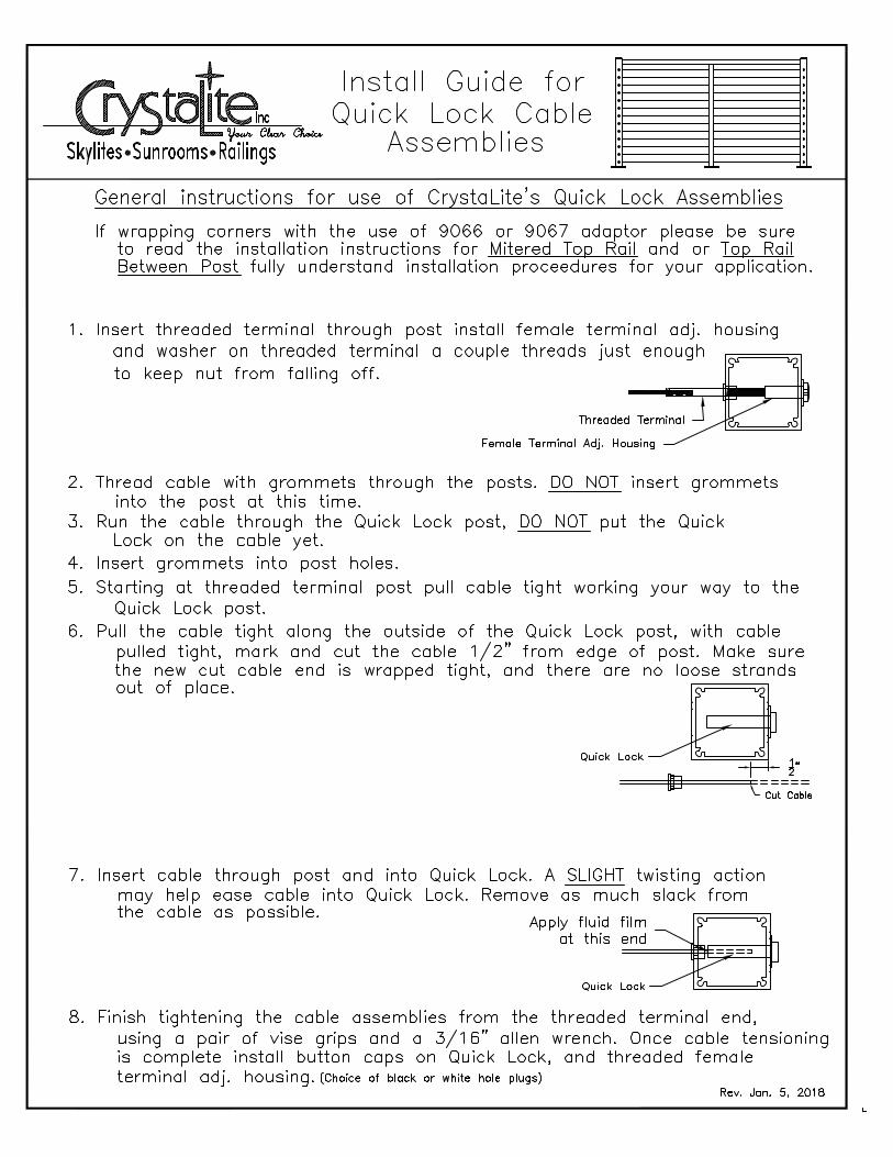
General instructions for use of CrystaLite's Quick Lock Assemblies
AutoCAD SHX Text
1. Insert threaded terminal through post install female terminal adj. housing
AutoCAD SHX Text
to keep nut from falling off.
AutoCAD SHX Text
2. Thread cable with grommets through the posts. DO NOT insert grommets
AutoCAD SHX Text
3. Run the cable through the Quick Lock post, DO NOT put the Quick
AutoCAD SHX Text
Lock on the cable yet.
AutoCAD SHX Text
4. Insert grommets into post holes.
AutoCAD SHX Text
5. Starting at threaded terminal post pull cable tight working your way to the
AutoCAD SHX Text
Quick Lock post.
AutoCAD SHX Text
6. Pull the cable tight along the outside of the Quick Lock post, with cable
AutoCAD SHX Text
pulled tight, mark and cut the cable 1/2" from edge of post. Make sure
AutoCAD SHX Text
the new cut cable end is wrapped tight, and there are no loose strands
AutoCAD SHX Text
12"
AutoCAD SHX Text
Cut Cable
AutoCAD SHX Text
into the post at this time.
AutoCAD SHX Text
7. Insert cable through post and into Quick Lock. A SLIGHT twisting action
AutoCAD SHX Text
may help ease cable into Quick Lock. Remove as much slack from
AutoCAD SHX Text
the cable as possible.
AutoCAD SHX Text
8. Finish tightening the cable assemblies from the threaded terminal end,
AutoCAD SHX Text
Rev. Jan. 5, 2018
AutoCAD SHX Text
out of place.
AutoCAD SHX Text
Threaded Terminal
AutoCAD SHX Text
Female Terminal Adj. Housing
AutoCAD SHX Text
and washer on threaded terminal a couple threads just enough
AutoCAD SHX Text
If wrapping corners with the use of 9066 or 9067 adaptor please be sure
AutoCAD SHX Text
to read the installation instructions for Mitered Top Rail and or Top Rail
AutoCAD SHX Text
Install Guide for
AutoCAD SHX Text
Quick Lock Cable
AutoCAD SHX Text
Assemblies
AutoCAD SHX Text
Between Post fully understand installation proceedures for your application.
AutoCAD SHX Text
using a pair of vise grips and a 3/16" allen wrench. Once cable tensioning
AutoCAD SHX Text
is complete install button caps on Quick Lock, and threaded female
AutoCAD SHX Text
terminal adj. housing.
AutoCAD SHX Text
(Choice of black or white hole plugs)
AutoCAD SHX Text
Apply fluid film at this end
AutoCAD SHX Text
Quick Lock
AutoCAD SHX Text
Quick Lock

PA
GE
1 O
F 3
E
stim
ate
Onl
y
Dea
ler
PO
Dea
ler:
Attn
:
RA
ILIN
G W
OR
KS
HE
ET
Pho
ne:
Fax:
Dat
e:
9000
9001
9039
9036
9002
9023
D
eck
Mo
un
t
W
hit
e
Alm
on
d
Gre
en
Bro
nze
S
ilver
Gre
y
Bla
ck
36
” ta
ll
42”
tall
Fie
ld M
ea
sure
by:
Cry
staL
ite
Inst
all
ed
by:
Cry
staL
ite
Oth
er
FO
B:
Dea
ler
Jo
bsi
te
C
ust
om
Gla
ss C
olo
r: (
if ap
plic
able
)
C
lear
B
ron
ze
A c
om
ple
ted
Sid
e
Mo
un
t W
ork
she
et
is
RE
QU
IRE
D f
or
OR
DE
R
De
ck
Ma
teri
al:
S
ide
Mo
un
t
No
te:
Gla
ss o
rder
ed a
fter
mea
sure
men
t o
f in
stal
led
rai
ling
.
Fla
ts:
Sta
irs:
Ga
tes:
1/
4” G
lass
P
icke
t
SS
Cab
le
1/
4” G
lass
P
icke
t
SS
Cab
le
1/4”
Gla
ss
Pic
ket
S
S C
able
G
ray
O
ther
R
esid
enti
al
Co
mm
erci
al
NO
T F
OR
US
E O
N S
TAIR
S
4 5/1
63
3 /8
2 3 /
42
3 /8
22
3 /8
TO
P R
AIL
AN
D P
OS
TS
CO
MP
AT
IBIL
ITY
MO
UN
TIN
G
CO
LOR
TO
P R
AIL
LOC
AT
ION
HE
IGH
T
INF
ILL
AR
EA
S
T
RA
DIT
ION
AL
CO
NF
IGU
RA
TIO
N
P
ost
to
Po
st
O
ver
the
Top
D
ou
ble
To
p R
ail
CO
NF
IGU
RA
TIO
N
N
o B
ott
om
Rai
l
N
o C
able
Sp
read
er
CA
BL
E O
PT
ION
S
N
o B
ott
om
Rai
l
W
ith
Cab
le S
pre
ader
(
dec
k m
ou
nt
on
ly)
B
ott
om
Rai
l
N
o C
able
Sp
read
er
B
ott
om
Rai
l
W
ith
Cab
le S
pre
ader
MIS
C I
TE
MS
NO
TE
S
9036
To
p R
ail
2-3/
4”
2-3/16”
9002
To
p R
ail
4-5/
16”
2-1/16”
9023
To
p R
ail
3-3/
8”
2-3/16”
9039
To
p R
ail
2-3/
8”
2-5/8”
9001
To
p R
ail
2”
2-1/8”
9000
To
p R
ail
2-3/
8”
2-1/8”
1-3/
4”
9005
2-1/
2”
9006
3-1/
2”
9060
PO
ST
SIZ
ES
__
____
___
N
ot
By
Cry
staL
ite
A
s in
dic
ated
on
PA
GE
3F
IEL
D F
AS
TE
NE
RS
:

Pro
vid
e a
sket
ch o
f yo
ur
dec
k d
imen
sio
ns
Ind
icat
e p
ost
siz
e &
lo
cati
on
s w
ith
th
e fo
llow
ing
sym
bo
ls:
(op
tion
al)
Ind
icat
e ex
isti
ng
po
st l
oca
tio
ns
wit
h
1-3/
4” (
9005
)2-
1/2”
(90
06)
3-1/
2” (
9060
)
WIN
D L
OA
D
Sta
nd
ard
Cry
staL
ite
Det
ails
Ind
icat
e S
tair
Lo
cati
on
s an
d D
irec
tio
n
Est
imat
ed D
eale
r C
ost
qu
ote
go
od
fo
r 30
day
s
Tota
l Li
nea
l F
eet
EV
ER
ET
T p
ho
ne
: 1
-80
0-6
66
-60
65
fa
x: 4
25
-25
8-6
73
4
SP
OK
AN
E p
ho
ne
: 1
-80
0-3
82
-54
03
fa
x: 5
09
-92
1-2
13
7
SA
LE
M p
ho
ne
: 1
-80
0-6
64
-12
57
fa
x: 5
03
-39
1-0
97
4
mp
hex
po
sure
Cab
le S
pre
ader
PA
GE
2 O
F 3
LA
YO
UT
SK
ET
CH
WC
Wra
pp
ed C
orn
erA
dap
ter
Pla
stic
Gro
mm
et
TT
Thre
aded
Ter
min
al(s
ho
p s
wag
ed)
3-1/
2” P
ost
3-1/
2” P
ost
FST
TFi
eld
Sw
aged
Thre
aded
Ter
min
al
QL
Qui
ck L
ock
SM
Sur
face
Mo
unt
(sh
op
sw
agg
ed)
FST
TFi
eld
Sw
aged
Thre
aded
Ter
min
al
2-1/
2” P
ost
2-1/
2” P
ost
TT
Thre
aded
Ter
min
al(s
ho
p s
wag
ed)
THTh
read
ed H
ous
ing
THTh
read
ed H
ous
ing
THTh
read
ed H
ous
ing
THTh
read
ed H
ous
ing
BW
Bev
eled
Was
her
SM
Sur
face
Mo
unt
(sh
op
sw
agg
ed)
FST
TFi
eld
Sw
aged
Thre
aded
Ter
min
al
SM
Sur
face
Mo
unt
(sh
op
sw
agg
ed)
TBS
urfa
ce M
oun
t Tu
rnb
uckl
e(f
ield
sw
aged
)
THTh
read
ed H
ous
ing
CA
BL
E F
AS
TE
NE
R C
ON
FIG
UR
AT
ION
SIF
AP
PL
ICA
BL
E

PA
GE
3 O
F 3
SID
E M
OU
NT
(F
AS
CIA
) W
OR
KS
HE
ET
Rec
omm
end
1/2”
min
.fro
m b
otto
m o
f Fas
cia.
Fa
scia
Bo
ard B
loc
kin
g
EX
AM
PL
E:
2 x
8
F
lush S
pac
er L
eng
ths
Off
set
3/8”
Typ
.
Cu
sto
m
Top:
Bot
tom
:
This
Sid
e M
ount
Wor
kshe
etis
REQ
UIR
ED f
or A
LL O
RD
ERS
whe
n Si
de M
ount
is
requ
este
d
F
AS
TE
NE
RS
NO
T B
Y C
RY
ST
AL
ITE
DE
CK
MO
UN
T F
AS
TE
NE
RS
#
14 x
3"
PH
SM
S
#
14 x
4"
PH
SM
S
3/
8"
x _
____
___
(ad
dit
ion
al m
ach
inin
g c
ost
s)
SID
E M
OU
NT
FA
ST
EN
ER
S
LA
G I
NT
O B
LOC
KIN
G
1/
4” x
3”
SS
Lag
Scr
ew
1/
4” x
4”
SS
Lag
Scr
ew
1/
4” x
__
SS
Lag
Scr
ew
3/
8"
x _
____
___
TH
RO
UG
H B
OLT
S W
/ N
UT
& W
AS
HE
RS
1/
4”-2
0 x
2-1/
2” S
S
1/
4”-2
0 x
3” S
S
1/
4”-2
0 x
3-1/
2” S
S
1/
4”-2
0 x
4” S
S
1/
4”-2
0 x
____
SS
3/
8"
x _
____
___
CO
NC
RE
TE
AP
PL
ICA
TIO
NS
1/
4”-1
6 x
3-3
/4”
SS
Wed
ge
An
cho
r
# o
f P
ost
s
Ple
ase
fill o
ut s
eper
ate
shee
ts if
di
ffere
nt p
ost d
imen
sion
s ar
e re
quire
d fo
r sa
me
job.
Rim
Jo
ist
EX
AM
PL
E:
2 x
8
FA
ST
EN
ER
S
Rec
omm
ende
d 1”
Fro
mE
dge
of R
im J
oist
De
ck
Th
ick
ne
ss
Po
st L
eng
th B
elo
w
Top
Ho
le
Bo
tto
m H
ole
FRO
M T
OP
OF
DE
CK
FRO
M T
OP
OF
DE
CK
5/1
6”
x 8
Co
mp
. D
ec
kin
gE
XA
MP
LE
:

IMPORTANT: CRYSTALITE WILL MAKE ALL DEDUCTIONS BASED ON THESE MEASUREMENTS
DECK / FLAT
MEASURING SHEET FOR RAIL GLASSDealer Dealer PO Date
IMPORTANT: CRYSTALITE WILL MAKE ALL DEDUCTIONS BASED ON THESE MEASUREMENTS
All measurements should be made from the deck side looking out.Make all measurements from the Bottom of the Bottom Rail to the Bottom of the Top Rail.CrystaLite will make all required deductions based off these measure-ments.Height measurements for Glass in a 36” deck mounted rail system should be 30 7/8” CrystaLite will deduct 7/8” from this.Height measurements for Glass in a 42” deck mounted rail system should be 36 7/8” CrystaLite will deduct 7/8” from this.
QTY T L TLBR BLTR
ADDITIONAL MEASUREMENTS FOR STAIRSADDITIONAL MEASUREMENTS FOR STAIRS / SLOPESLOPE
MARK
1
2
3
4
5
6
7
8
9
10
11
12
13
14
15
16
17
18
19
20
21
22
23
24
25
26
NOTE RB
CLEAR BRONZE GREY OTHER
BOTTOMLENGTH
RIGHTSIDE
TOPLENGTH
LEFTSIDE
TOP LEFTTO BOTTOMRIGHT
BOTTOMLEFT TOTOP RIGHT
DECK / FLAT INSTALLATION
STAIR / SLOPE INSTALLATION
B
R
TL
BLTR
TLBR
Bottom of Bottom Rail
Bottom of Top Rail
R
BBottom of Bottom Rail
Bottom of Top Rail
IMPORTANT: CRYSTALITE WILL MAKE ALL DEDUCTIONS BASED ON THESE MEASUREMENTS
EDGE GAP DEDUCT
Standard1” Edge Gap
Custom__________