
GLASS FIBER REINFORCED METAL PRESSURE VESSEL …
113
f -. G LAS S FIB E P FE I N FOR C ED f DESIGN GUIDE MET!l.L PRESSU .t Industries, Inc.) (structural es CSCL 11D TOPICAL REPORT NASA CR-120917 N73-1B932 Unclas (;3/32 64685 GLASS FIBER REINFORCED METAL PRESSURE VESSEL DESIGN GUIDE by R. E. Landes STRUCTURAL COMPOSITES INDUSTRIE Azusa, California In Collaboration With· THE BOEING COMPANY Seattle, Washington Pr"pared for .. AERONAUTICS AND SPACE ADMINISTRATION NASA-Lewis Research Center - Contract NAS 3-14380 .failles R. Faddou( ProjeCT Manager RfPRODUCfO BY ; u.s. OEPARTMfNT OF COMS ER VICE .. SPRINGFIElD. VA.
Transcript of GLASS FIBER REINFORCED METAL PRESSURE VESSEL …

f -. ~- G LAS S FIB E P FE I N FOR C ED f (Nr>.Si\-CR-120:~7~ESSEL DESIGN GUIDE
MET!l.L PRESSU .t Industries, Inc.) (structural CompoS~ es CSCL 11D
~!~C TOPICAL REPORT
NASA CR-120917
N73-1B932
Unclas (;3/32 64685
GLASS FIBER REINFORCED METAL
PRESSURE VESSEL DESIGN GUIDE
by
R. E. Landes
STRUCTURAL COMPOSITES INDUSTRIE Azusa, California
In Collaboration With·
THE BOEING COMPANY Seattle, Washington
Pr"pared for .. N~T10NAL AERONAUTICS AND SPACE ADMINISTRATION
NASA-Lewis Research Center
- Contract NAS 3-14380
.failles R. Faddou( ProjeCT Manager
RfPRODUCfO BY
; '~~'R~~Af,d~CHN'CAl u.s. OEPARTMfNT OF COMS ER VICE
.. SPRINGFIElD. VA. 221~fRCE
1. Report No. I 2. Goyernment Acc.sion No. 3. Recipient's Catalog No.
NASA CR-120917 4. Title and Subtitle 5. Report Dilte
GLASS FIBER REINFORCED METAL July 1972
PRESSURE VESSEL DESIGN GUIDE 6. Performing Organization Code
7. Author(sl 8. Performing Organization Report No.
R. E. Landes 10. Work Unit No.
9. Performing Organization Name and Address
Structural Composites Industries 11. Contract or Grant No.
6344 N. Irwindale Ave. NAS 3-14380 Azusa, California 91702 13. Type of Report and Period Covered
12. Sponsorinr ~ncy Name iIrld Address Nationa eronautics and Space Administration
Contractor Report
Lewis Research Center 14. Sponsoring Agency Code
21000 Brookpark Rd Cleveland, Ohio 44135 15. Supplementary Notes
Proj ec t Manage r, James R. Faddoul Materials and Structures Division NASA Lewis Research Center Cleveland, Ohio 44135
16. Abstract
This Engineering Guide presents curves and general equations for safelife
design of lightweight glass fiber reinforced (GFR) metal pressure vessels operating under anticipated Space Shuttle service conditions. The high composite vessel weight efficiency is shown to be relatively insensitive to shape, providing increased flex ibi I ity to designers establ ish ing spacecraft configurations. Spheres, oblate spheroids, and cylinders constructed of GFR Inconel X-750, 2219-T62 aluminum, and cryoformed 301 stainless steel are covered; design parameters and performance efficiencies for each configuration are compared at ambient and cr~ogenic temperature for an operating pressure range of 690 to 2760 N/cm2 (1000 to 4000 psi). Design variables are presented as a function of metal shell operating to sizing (proof) stress ratios for use with fracture mechanics data generated under a separate task of this program. Application of the fracture mechanics information to the data of th is Guide provides a basis for appropriate se lection of vessel proof test levels and safelife design configurations for Space Shuttle composite tanks with load sharing liners.
17. Key Word. {Suggested by Author{.11 18. Distribution Stltement
Pressure Vessel 2219-T62 Aluminum Design Guide Cryoformed 301 Glass Fiber Reinforced Stainless Steel Unci ass i fie d Unlimited Inconel X750 STA
19. Security Ciani!. lof this report I 20. Security CI_"if. (of this ~gel 21. No. of Pages
Unclassified Unclassified II').. • • For sale by the National Technical Information SerVice, Springfield, Virginia 22151
NASA-C-lh~ rR('\ h-711

FORmJRD
This report was prepared for The Boeing Company by R. E. Landes of Structural Composite s Industrie s, Inc. (SCI) under the cognizance of E. E. Morris, Vice Pre sident. The report summarize s the fir st task of a three task program being conducted as a joint effort by SCI and the Re search and Engineering Division of The Boeing Company under National Aeronautics and Space Adm.inistration Contract NAS 3-14380.
Guidance and many helpful sugge stions we re provided during the effort by The Boeing Company Technical Leader, Mr. W. D. Bixler, and the NASA Lewis Research Center Project Manager, Mr. James R. Faddoul.
II

TABLE OF CONTENTS
Page
I. INTRODUCTION AND SUMMARY 1
II. BACKGROUND 2
A. SPACE SHUTTLE TANKAGE 2
B. GFR METAL TANK DESIGN PHILOSOPHY 2
C. COMPUTER PROGRAM FOR VESSEL DESIGN AND 5
ANALYSIS
D. FRACTURE MECHANICS CONSIDERATIONS 6
Ill. SPECIFIC DESIGN CRITERIA 8
A. GEOMETRIC PARAMETERS 8
B. SHELL MA TERIALS 8
C. F ABRICA TION CRITERIA 9
D. SIZING CRITERIA 9
E. OPERA TING CONDITIONS 10
F. F ALLURE CRITERIA 1 1.1
G. OPTIMUM VESSEL 10
H. BURST STRENGTH 11
IV. DESIGN EQUATIONS AND CURVES 12
A. GENERAL CONSIDERATIONS 12
1. Metal Shell Operating To Sizing Stre s s Ratio 12 Effects
2. Constrictive Wrap Buckling Equations 14
3. Internal Volume Relations 16
iii

TABLE OF CONTENTS {continued}
Page
IV. DESIGN EQUATIONS AND CURVES {continued}
B. GFR 2219-T62 ALUMINUM VESSELS 1 7
l. Sizing / Operating Detail s 17
2. Metal Shell Thicknes s 1 H
3. Longitudinal Compo site Thickne s s 19
4. Hoop Composite Thickness 20
5. Vessel Burst Pressure 20
6. Ve s scI PerforITlance and Weight 2.1
C. GFR INCONEL X-750 VESSELS 2.1
1. Sizing/Operating Details 21
2. Metal Shell Thickne s s 23
3. Longitudi nal COITlPO site Thickness 25
4. Hoop C OITlpO site Thic kne s s 26
5. Vessel Burst Pressure 27
6. Ve s scI Performance and Weight 28
D. GFR 301 STAINLESS STEEL VESSELS 28
1. Sizing/Operating Details 28
2. Metal Shell Thickness 30
3. Longitudinal Compo site Thickne s s 32
4. Hoop C OITlpO site Thickne s s 32
iv

TABLE OF CONTENTS (continued)
Page
IV. DESIGN EQUATIONS AND CURVES (continued)
D. GFR 301 STAINLESS STEEL VESSELS (continued)
5. Vessel Burst Pressure 33
6. Ve s se1 Performance and Weight 33
E. SAMPLE DESIGNS 34
V. SAFEFLIFE VERSUS BURST FACTOR OF SAFETY DESIGNS 38
VI. CONCLUDING REMARKS 39
TABLE 1 -
REFERENCES
MATERIAL PROPERTIES USED IN PARAMETRIC STUDY
v
40-43
96

FIGURE 1
FIGURE 2
FIGURE 3
FIGURE 4
FIGURE 5
FIGURE 6
FIGURE 7
FIGURE 8
FIGURE 9
FIGURE 10
FIGURE 11
FIGURE 12
LIST OF FIGURES
Stress-Strain Diagram for Glass Filament Reinforced Metallic Shell
Vessel Configurations and Wrap Patterns
Linearization of Metal Shell Stre ss/ Strain Curve
Sizing Pressure Requirements for Ambient and Cryogenic Operated GFR 2219-T62 Aluminum Pre s sure Ve s sels
Metal Shell Offset Yield Strength at Ambient and Cryogenic Temperature for Sized GFR 2219-T62 Aluminum Spheres
Metal Shell Offset Yield Strength at Ambient and Cryogenic Temperature for Sized Completely GFR 2219-T62 Aluminum Oblate Spheroids and Cylindrical Vessels
Metal Shell Offset Yield Strength at Ambient and Cryogenic Temperature for Sized Hoop GFR 2219-T62 Aluminum Cylinder s
Metal Shell Thicknes s Parameter for GFR 22l9-T62 Aluminum Pressure Vessels
Longitudinal Filament Thickne ss Parameter for Completely GFR 2219-T62 Aluminum Pressure Vessels
Hoop Filament Thickne ss Parameter for GFR 22l9-T62 Aluminum Vessels
Ambient Burst Pressure Factors for Completely GFR 2219-T62 Aluminum Pressure Vessels
Burst Pressure Factors at 77 0 K (-3200 F) for Completely GFR 2219-T62 Aluminum Pressure Vessels
vi
Page
44
45
46
47
48
49
50
51
52
53
54
55

FIGURE 13
FIGURE 14
FIGURE 15
FIGURE 16
FIGURE 17
FIGURE 18
FIGURE 19
FIGURE 20
LIST OF FIGURES (continued)
Burst Pressure Factors at 20 0 K (-4230 F) for Completely GFR 2219-T62 Aluminum Pressure Vessels
Ambient and Cryogenic Burst Pressure Factors for Hoop GFR 2219-T62 Aluminum Pressure Vessels
Performance Factor for Ambient Operated GFR 2219-T62 Aluminum Pressure Vessels
Performance Factors for GFR 2219-T62 Alurninllm Pressure Vessels Operated at 77 0 K (-3200 F)
Performance Factors for GFR 2219-T62 Aluminum Pressure Vessels Operated at 20 0 K (-423 0 F)
Sizing Pressure Requirements for Ambient and Cryogenic Operated GFR Inconel X-750 Pressure Vessels
Metal Shell Offset Yield Strength at Ambient and Cryogenic Temperature for Sized GFR Inconel X-750 Spheres
Metal Shell Offset Yield Strength at Ambient and Cryogenic Temperature for Sized Completely GFR Inconel X-7S0 Oblate Spheroids and Cylindrical Vessels
FIGURE 21 Buckling Sensitivity. IndiCator for H00p GRF Inconel X-750 Pressure Vessels
FIGURE 22 Metal Shell Offset Yield Strength at Ambient Temperature for Sized Hoop GFR Inconel X-750 Cylinders
FIGURE 22B Metal Shell Offset Yield Strength at Liquid Nitrogen Temperature for Sized Hoop GFR Inconel X-7S0 Cylinders
FIGUEE 22C Metal Shell Offset Yield Strength at Liquid Hydrogen Temperature for Sized Hoop GFR Inconel X-750 Cylinders
vii
56
57
58
59
60
61
62
63
64
65
66
67

FIGURE 23
FIGURE 24
FIGURE 25
FIGURE 26
FIGURE 27
FIGURE 28
FIGURE 29
FIGURE 30
FIGURE 31
FIGURE 32
FIGURE 33
FIGURE 34
FIGURE 35
LIST OF FIGURES (continued)
Metal Shell Thickness Parameter for GFR Inconel X-750 Pressure Vessels
Metal Shell Diameter to Thickness Ratios for Buckling Sensitive Completely GFR Inconel X-750 Pre ssure Ve ssels
Metal Shell Diameter to Thickne s s Ratios for Buckling Sensitive Hoop GFR Inconel X-750 Pressure Vessels
Longitudinal Filament Thickne ss Parameter for Completely GFR Inconel X-750 Pressure Ve ssels
Hoop Filament Thickness Parameter for GFR Inconel X- 850 Cylindrical Ve ssels
Ambient Bur st Pressure Factors for Completely GFR Inconel X-750 Pressure Vessels
Burst Pressure Factors at 77 0 F (-3200 F) for GFR Inconel X-750 Pressure Vessels
Burst Pressure Factors at 22 0 K (-423 0 F) for GFR Inconel X-750 Pressure Vessels
Burst Pressure Factor Variation for Buckling Sensitive Completely GFR Inconel X-750 Cylindrical Pressure Vessels
Performance Factors for Ambient Operated GFR Inconel X-750 Pressure Vessels
Performance Factors for GFR Inconel X- 750 Ve ssels Operayed at 77 0 F (- 320 0 F)
Performance Factors for GFR Inconel X-750 Vessels Operated at 20 0 K (-423 0 F)
Sizing Pressure Requirements for Ambient and Cryogenic Operated GFR 301 Stainle s s Steel Pressure Vessels
viii
Page
68
69
70
71
72
73
74
75
76
77
78
79
80

LIST OF FIGURES (continued)
FIGURE 36 Metal Shell Offset Yield Strength at Ambient and 81 Cryogenic Temperatures for Sized GFR 301 Stainle s s Steel Sphe re s
FIGURE 37 Metal Shell Offset Yield Strength at Ambient and 82 Cryogenic Temperature for Sized Completely GFR 301 Stainle ss Steel Oblate Spheroids and Cylindrical Vessels
FIGURE 38 Buckling Sensitivity Indicator for Hoop GFR 301 Stainle ss 83 Steel Pressure Vessels
FIGURE 39 Metal Shell Offset Yield Strength at Ambient and 84 Cryogenic Temperature for Sized Hoop GFR 301 Stainless Steel Cylinders
FIGURE 40 Metal Shell Thickness Parameter for GFR 301 Stainless 85 Steel Pressure Vessels
FIGURE 41 Longitudinal Filament Thickne ss Parameter for 86 Completely GFR 301 Stainless Steel Spheres
FIGURE 42 Longitudinal Filament Thickness Parameter for 87 Completely GFR 301 Stainless Steel Oblate Spheroid and Cylindrical Vessels
FIGURE 43 Hoop Filament Thickness Parameter for GFR 301 Stainless 88 Steel Cylindrical Vessels
FIGURE 44 Ambient Burst Pressure Factors for Completely GFR 301 89 Stainless Steel Pressure Vessels
FIGURE 45 Burst Pressure Factors at 77 0 K (-3200 F) for Completely 90 GFR 301 Stainless Steel Pressure Vessels
FIGURE 46 Burst Pressure Factors at 20 0 K (-4230 F) for Completely 91 GFR 301 Stainless Steel Pressure Vessels
FIGURE 47 Ambient and Cryogenic Burst Pressure Factors for 92 Hoop GFR 301 Stainless Steel Pressure Vessels
ix

LIST OF FIGURES (continued)
FIGURE 48 Performance Factors for Ambient Operated GFR 301 93 Stainless Steel Pressure Vessels
FIGURE 49 Performance Factors for GFR 301 Stainle ss Steel 94 Vessels Operated at 77 0 K (-320°F)
FIGURE 50 Performance Factors for GFR 301 Stainle ss Steel 95 Vessel Operated at 200 K (-423°F)
x

LIST OF SYMBOLS
A Minor semi-axis of an oblate spheroid, meters (feet)
B Major semi-axis of an oblate spheroid, meters (feet)
r ; .
1
D
El
EL
F bc
F bo
F bs
F ty
F' ty
F tu
F tuf
K e
C Oe fficient s defined in text
Vessel diameter, meters (feet)
Boss diameter, cm (inch)
Modulus of elasticity, GN/m2
(psi)
Secondary modulus of metal, computer input value, GN/m 2
(psi)
Primary modulus of metal, computer input value, GN/m2
(psi)
Constrictive wrap buckling strength of a cylinder, MN 1m 2 (psi)
Constrictive wrap buckling strength of an oblate spheroid, MN/m 2
(psi)
Constrictive wrap buckling strength of a sphere, MN 1m 2 (psi)
2 Classical elastic buckling strength, MN/m (psi)
Tensile yield strength, MN/rn2
(psi)
Offset tensile yield strength, MNI m 2
(psi)
Ultimate tensile strength of metal, MNI m 2
(psi)
Ultimate strength of filaments, MN 1m 2 (psi)
Burst pressure factor defined as Kb = Pb, TIpo, T' dimensionless
Longitudinal filament thickness parameter defined as K = t It
l, dimensionless
e e
XI

K P
K sd
K w
K s
L
p s
p vg
R a
SYL
t c
t e
t hc
LIST OF SYMBOLS
Hoop filament thickness parameter defined as Kh = th/tl
, dimensionle s s
Metalzshell thickne s s parameter defined as Kl = P s (D/tl
), N/cm (psi)
Sizing pre s sure parameter defined as K p = p Ip T' s 0,
dimensionle s s
De sign value for metal shell operating to sIzIng stre ss ratio defined as K = TIFf T' dimensionless
sd 0, max ty,
Ve s sel performance factor defined as K = p TV Iw , Jig (in-lbf/lbm) W 0,
Metal shell operating to sizing stress ratio, dimensionless
Vessel overall length, meters (feet)
Burst pressure, N/cmZ ~psi)
Operating pressure, N/cmZ
(psi)
Sizing pre s sure, N I cm 2
(psi)
Volume fraction of fibers in composite, dimensionless
Vessel radius at equator of head, meters (feet)
Metal tensile yield strength, computer input value, MN 1m Z (psi)
Longitudinal compo site thickne s s, cm (inch)
Longitudinal filament thickne ss, cm (inch)
Hoop filament thickne s 5, cm {inch}
Hoop composite thickness, cm (inch)
Metal shell thickne s s, cm (inch)
xii

T o
v
w
x
LIST OF SYMBOLS
Operating temperature, oK (oF)
3 3 Vessel internal volume, m (feet)
Vessel weight, grams (Ibm)
Radial distance from vessel axis of rotation to head contour point, meters (feet)
Z Normalized coordinate defined as Z = X/R, dimensionless
ex o
er c
<J wf
a
Longitudinal wrap angle, radians (degrees)
Poisson's ratio, dimensionless
Compressive stress in metal shell after sizing, MN/m2
(psi)
Tensile stress in metal shell at operating condition, MN/m2
(psi)
Tensile stress in filaments at operating condition, MN/m2
(psi)
Tensile stress in metal shell at sizing condition, MN/m2 (psi)
Tensile stress in filaments at wrap condition, MN/m2
(psi)
xiii
LIST OF SYMBOLS
SUBSCRIPTS;
A
c
cr
e
h
H
max
min
N
o
Evaluated at ambient temperature
Hoop wrapped cylinder
Critical value
Value for longitudinal filaments
Value for hoop filaments
Evaluated at liquid hydrogen temperature, 20 0 K (-423°F)
Maximum value
Minimum value
Evaluated at liquid nitrogen temperature, 77o K, (-320°F)
Oblate spheroid
oc Completely overwrapped cylinder
s Sphere
T Value at any tempe rature
J Hoop direction
xiv

Quantitx
CONVERSION OF U. S. CUSTOMARY UNITS TO THE INTERNATIONAL SYSTEM OF UNITS
U. s. Customary Conver Ston Unit Factor SI Unit
Density Ibm/in. 3
27.68xlO 3
kilogram s /meter 3 3
(kg/m )
Length ft 0.3048 meters (m) in 0.0254 meters (m)
Stress, Pressure psi 6.895 x 10 3 2 2
newtons/meter (N/m) Modulus
Temperature (oF + 460) 5/9 degree s Kelvin (oK)
Prefixes to indicate multiples of units are as follows:
Prefix MultiEle
giga (G) 109
mega (M) 106
kilo (k) 103
milli (m) 10- 3
micro (..u') 10- 6
1 Multiple value given in U. S. Customary Unit by conversion factor to obtain equivalent value in SI unit
xv

xvi

1. INTRODUC TION AND SUMMAR Y
The potential of glass fiber reinforced (GFR) metal tanks for space vehicle application has been and continue s to be demonstrated by a serie s of NASA-LeRC technology development programs conducted during the past ten years. The objectives of the current program, Contract NAS 3-14380, are to (1) evaluate designs of GFR metal tanks of three liner materials, (2) determine experimentally the critical and subcritical flaw growth of the se metallic materials using uniaxial specimens, and (3) determine experimentally the applicability of the uniaxial specimen data by testing GFR metal tanks with flaws, to develop a de sign method for guaranteeing the cyclic life of overwrapped tanks based on the initial sizing cycle. The program is being conducted as a joint effort by the Re search and Enginee ring Division of The Boeing Company and Structural Composites Industries, Inc. (SCI).
This handbook, summarizing the design evaluation phase, was prepared as a design guide for pressure vessel engineers concerned with a specific GFR metal tank design or a general tank trade-off study. Design philo sophy and general equations and curve s are provided for the safe life ':.!,' sign of GFR metal tanks operating under anticipated Space Shuttle service conditions. The de sign guide cover s sphere s, oblate spheroids, and cylinders constructed of GFR Inconel X-750, 22l9-T62 aluminum, and cryoformed 301 stainle ss steel. Efficiencie s of de signs for each configuration are compared at ambient and cryogenic temperatures for an operating pressure range of 690 to 2760 N/cm2 (1000 to 4000 psi).
-1-

II. BACKGROUND
A. SPACE SHUTTLE TANKAGE
The Space Shuttle mis sion consists of delivery and retrieval of a variety of payloads to and from earth orbit on a regular and frequent schedule. It's primary objective is to lower present cost of a payload pound delivered to orbit by a factor of lOO. This require s development of a manned vehicle, with cost-effective launch system which can be launched to earth orbit, perform specific logistics, and re-enter to a landing site adjacent to the pad. The Shuttle configurati( n has evolved to an orbiter vehicle, with disposal liquid oxygen/liquid hydrogen tank and solid rocket booster. As noted in Reference 1, the reusable orbiter vehicle rnust be refurbished to flight status following each mission, with a IOO-mission life required, and a SOO-mission life <lS a design objective.
The Space Shuttle Orbiter will have reusable, cyclically loaded, tanks to contain gases and liquids. Tank~cge comprises a significant portion of the structural weight, and because the orbiter is extremely weight critical, many of the vessels are candidate for high-strength, light weight, composite metal/ filament overwrap construction.
B. GFR METAL TANK DESIGN PHILOSOP:l.Y
The primary design objectives of a glass filament composite shell with an inner load carrying metal shell is to obtain maximum operating performance at minimum weight and to provide a comparable or improved safelife de sign over ba sic metal tank construction. Thick liner s that share loads with the filament-wound shell offer an excellent approach to workable, low weight, fluid storage vessels. The functions and interactions of the parameters of filament reinforced metal shell ve ssels have been evaluated in detail by NASA and by SCI in past program s to establish optimum stress/ strain relationships between the metal and fiber shells from strength, load, and strain compatibility viewpoints.
Analytical work and te st evaluations have established many of the methods needed for analysis and rating of designs, and have indicated the technical problems which will be encountered with filament reinforced spheres, spheroids, and cylinders. They are related to the following factor s:
-2-

(1) Load and strain capability of the two types of material.
(2) Constrictive wrap buckling strength of the metal shell.
(3) Prestress (filament tensioning) set up between the two mate rials during fabrication and proof te sting (sizing).
(4) Effects of prestress into the plastic region of the metal shell.
(5) Thermal contraction characteristics of the various construction materials.
(6) Effects of cyclic and sustained loading on fatigue life and re sidual strength.
For a specific tank configuration and metal and filament shell materials, particular attention must be paid to relative shell thickne sse s and winding tension prestress (during fabrication, or pressure-sizing past the metal shell yield point after fabrication) to obtain the following most significant conditions:
Condition (1): Suitable stress/ strain relationships between the filament and metal shells to permit achievement of specified (optimum design) allowable operating/burst stresses in the filament and metal shells, simultaneously, at the operating/burst pressures and temperatures.
Condition (2): Suitable stress/ strain relationships between the shells to permit attairunent of a high fraction of the filament ultimate strength
Prior to exceeding the metal shell biaxial ductility capability
As the metal shells approaches its maximum strength capability
Condition (3): Preclude metal shell buckling due to constrictIve wrap stresses.
-3-

A schematic stress/strain diagram for a GFR metal tank is pre sented in Figure I, and is applicable to GFR spheres and sphe roids, as well as hoop wrapped and completely wrapped closed-end cylinders. With reference to that figure, a 1fload-bearing metal shell" is defined as one capable of resisting buckling at the compressive stress level (E) shown there (produced by external pre s sure from the overwrapped shell), when no bond exists between the two shells. The two shells are designed to ITlinimize the hystere sis loop of the liner in the ope ration-pre s sure-cye Ie stress range (E) to (J) to (E) [i. e., (E) to (J) is an elastic stress/ strain curve] .
Significantly different stress/ strain conditions are imposed on GFR metal tanks during application of the internal pre s sure s as sociated with tank fabrication, proof te sting, burst te sting, and operation. Figure 1 depict s the se state s for both shells during fabrication, after mandrel removal, and at the proof-pre ssure prestre s s, zero pre ssure, operating pressure, and burst pressure. It provides a basis for the ensuing discus sion, which repeatedly refer s to points depicted the re.
The ITletal shell may be held in a stre s s-free (strain-free) state of a ri-¥id mandrel while being overwrapped with tensioned filaITlcnts [ point (M) J. Upon ITlandrel reITloval, however, it will spring back into a compressive state, due to the overwrap pressure [point (0)]. The magnitude of COITlpre ssion at zero-interr~3.l-pre ssure equilibrium depends on the relative thicknesses and ITloduli of the overwrapped filaments and liners, as well as the bia:;dal stress-strain characteristics of the liner and the filaITlent-winding tension used during filaITlent-wound composite fabrication.
When the first pressure load (ps) is applied, the GFR metal tank is strained to the point (A), which is fixed by material properties and thickness and by the load. For factors of safety associated with the tankage and with the glass-filament and metallic ITlaterials now available, point (A) can be beyond the metal- shell yield point and plastic deformation may occur. In general, it can be said that the biaxial tensile strain produced in the liner by the initial " sizing" pre s sure may exceed 1 % and may be greater than 2%.
When the initial load is reITloved after plastic de forITlation, the liner will spring back along the offset, biaxial, elastic, strain-stress curve (A) - (E) and will be pushed into compression by external pressure from the overwrapped filalTIents until load equilibriulTI is reached at
-4-
point (E) [strain (G)]. The GFR metal tanks are designed so that point (E) does not exceed (a) the critical buckling-stress level of the liner in the absence of a bond between the two shells, or (b) a fixed fraction of the compressive elastic limit of the liner.
The operating-pressure level (Po) will always be less than ps. During the application of cyclic operating-pre ssure loads, therefore, the metal-liner strain range is betwee:n points (G) and (K).
c. COMPUTER PROGRAM FOR VESSEL DESIGN AND ANALYSIS
SCI developed the Reference 2 computer program, based on the preceeding discus sion, for use in de signing and analyzing complete GFR metal tanks wound with eitner geodesic or in-plane patterns along the cylinder and Over the end domes and complemented by circumferential windings in the cylinder. The program treats the filament shell by means of a netting analysis, which as sume s (1) constant stre s se s along the filament path, and (2) that the re sin make sane gligible structural contribution. The filament shell and the constant-thickne ss metal liner are combined by equating strains in the longitudinal and hoop directions and by adjusting the radii of curvature to match the combined material strengths at the design pressure; both the elastic and plastic portions of the metal-liner stress-strain relationship are considered in this analysis.
The program establishes optimum head contours and defines component thickne sse s and other dimensional coordinate s, as well as the shell stresses and strains at zero pressure and the design pressures, the filament path lengths, and the weights and volumes of the components and complete vessels. Sufficient program flexibility is available to permit analysis of cylinders overwrapped in the circumferential direction only.
The computer program also determines stresses and strains in both shells throughout the service-cycling history from a series of input pressures, composite temperatures, and metal-liner temperatures. This feature permits analyses of pressure and temperature cycles imposed on the ve ssel during fabrication and envirorunental testing, taking into account previous strains and loads. The computer program was used to conduct the parametric study of GFR-metal tanks reported in Reference 3, for design and analysis of GFR Inconel X-750 tanks described in Reference 4, and to develop the information contained in this de sign guide.
-5-
D. FRACTURE MECHANICS CONSIDERATIONS
In order to assure adequate service performance of most aerospace structures and in particular metal tankage, it is necessary to apply the principles of fracture mechanics to establishing design and operation requirements for such pressure vessels. This requires knowledge of fracture toughne s sand subcritical flaw growth behavior of candidate materials. The guidelines to the design of metal pressure vessels based on fracture mechanic s considerations are fully discus sed in Refe:;:-ence 5. Briefly, the proof test is a means of establishing the maximum possible initial flaw that can exist in the structure. This knowledge plus the sustained load and cyclic load flaw growth characteristic s of the mate rial/ environment combination can then be used to establish safe ratios of proof to operating stre s s leveL
Fracture mechanics methods have not yet been established for light weight, high strength compo site metal/ filament ove rwrapped tankage, but must be if the weight saving advantages of this construction concept are to be successfully applied to aerospace programs. GFR metal tanks apparently offer unique advantage s Ove r the metal tank from a fracture mechanic s viewpoint. During the sizing operation performed on a GFR metal tank the sizing stre s s exceeds the yield strength of the metal line r, thereby effectively screening a smaller flaw than possible in a comparable metal tank. The plastic deformation that take s place during the sizing ope ration may blunt the flaws and improve the subc ritical flaw growth characteristics of the metal liner. Secondly, the metal liners of GFR metal tanks are about one-half to one-third the thickne ss of comparable all-metal tanks and, therefore, are more prone to a leakage failure mode. Te sts of GFR metal tanks conducted to date, have shown that, during failure,
the liner mate rial can be contained by the overwrap re sulting in a nonshatterable design. Damage containment in case of a malfunction or failure is a very de sirable feature for Space Shuttle type applications. The filament overwrap, due to its restraining effect, might also offer some advantage in reducing c rack growth.
Since no theoretical methods have been developed to handle flaws subjected to general plastic deformation, it is necessary to empirically evaluate data to bette r understand the mechanic s of failure and subc ritical flaw growth for the se flaws. The required cmp; rical data is
-6-
currently being established by Boeing/SCI under the second and third phases of this contract, NAS 3-14380. The end result of this program is to establish a fracture control method which would guarantee safe se :"'vice life for GFR metal tanks.
-7-
III. SPECIFIC DESIGN CRITERIA
A complete discus sion of the effects of each de sign variable as sociated with GFR metal tanks is contained in Reference 3. Specific design variables established for thi s study and the range s in value s of inte re st to NASA arc summarized in the paragraphs that follow:
A. GEOMETRIC PARAMETERS
The selected vessel configurations include (1) spheres, (2) oblate spheroids, (3) circumferentially wrapped cylindrical vessels with hemispherical end closures, and (4) completely overwrapped cylindrical ve s scls with oblate spheroidal end closure s. Sc hematic s of each of the four configurations are pre sented in Figure 2. The pre s sure ve s sel internal volume range is 0.07 to 3,4 m 3 (2. S to 120 ft3), and the major axis inside diameter range is 0, lS to 1.8 meters (0, 5 to 6.0 feet) for all configurations. Axial port diameters are fixed at 20% of the vessel major axis inside diameter.
B. SHELL MATERIALS
The composite reinforcement selected by NASA for this study was S-90l continuous glass filaments impregnated with an epoxy resin. Inconel X-7S0 (ST A), 22l9-T62 aluminum, and cryoformed 301 stainle s s steel were selected as the constant thickness load bearing liner materials based on their compatibility with the glass filament-overwrap and the re sultant high GFR metal ve ssel weight efficiencie s. Propertie s of the se materials and the referenced literature from which they were obtained are pre sented in Table I.
Values for the tensile yield strength and "plastic" modulus of the metallic material s are not nece s sarily the same a s the conventional values. Since the Reference 2 computer program requires a bi-linear form for the metal shell stre s s / strain relation, actual stre ss/ strain curve s must be linearized according to the schematic of Figure 3. To arrive at a value of the plastic modulus (El) for a given metal, a straight line is passed through two stress/ strain points on the real curve defined by the filament operating strain and the filament brust strain. The inte rsection of this linear "plastic" curve with the elastic curve (defined by the real clastic modulus, E L) fixe s the computer value for yield strength (SYL).
-8-

C. F ABRICA TION CRITERIA
Filament Winding Patterns: Spheres - an axisymmetric, nmltiple angle wrap pattern which produce s a constant thickne s s glas s/ epoxy compo site shell. Oblate Sphc roids - a longitudinal-in-plane pattern. Closed End Cylindrical Vessels - a circumferential pattern over the cylindrical section only; and, longitudinal-in-plane pattern complemented by circumfe rential patte rn along cylindrical section. The se patterns are shown sc hematically in Figure 2 for each configuration.
Filament Winding Tension: 2.2 Newtons/roving-end (I /2 Ibf/ roving-end) producing a filament prestress of 164 MN/m 2 (23.8 ksi) which may be increased to a maximum practical value of 8.9 Newtons/rovingend (2 lbf/roving-end) when required for optimization.
Winding Support Mandrel: Rigid support for all vessels except hoop wrapped cylinders; pressure support may be used for hoop wrapped cylinders if required.
D. SIZING CRITERIA
All vessels are sized (proof tested) prior to operation.
Metal Shell Sizing Stress: Computer derived optimum for filament reinforced metal; less than or equal to tensile yield strength for unreinforced metal portions of vessel.
Sizing Temperature: Ambient for GFR Inconel X-750 and 221 9-T 62 aluminum ve s sel s; 77 0 K (-3200 F) for GFR 301 stainles s steel vessels (bare metal is initially cryostretched).
Zero Pressure After Sizing: Compressive stresses in the metal shall not exceed (1) the compre s sive allo".;rable established for each type metal shells, or (2) the constrictive wrap buckling allowable stress
whichever is critical.
-9-

E. OPERA TING CONDITIONS
Pressure: 690 to 2760 N/cm2 (1000 to 4000 psi)
Temperature: Extremes are 344°K (+l60 0 F) to liquid hydrogen at 20 0 K (-423 0 F).
Cyclic Loads: 2400 full zero to operating pressure cycles [100 flights x (5 checkout cycles prior to flight + 1 flight cycle) x scatter factor of 4 = 2400 cycle s ] .
Filament Operating Stress: Shall be .: 1380 MN/m2
(200, 000 psi) at ambient (75 0 F) and'::: 1720 MN/ m r (250,000 psi) at cryogenic temperatures (see Table I).
Metal Shell Operating Stress Levels: 75, 85, and 95% of the ITleta1 shell offset yield stress (Fl ).
ty
F. FAILURE CRITERIA
For cOITlpletely overwrapped metal vessels, the burst pressure is defined to be the pressure at which the longitudinal Or hoop filament stress exceeds the ultimate strength of the fiber or the ultimate strain of the metal. For hoop wrapped cylindrical vessels, the burst pressure is defined to be the pressure at which (1) the hoop filament stress exceeds the ultimate fiber strength, or (2) the unreinforced metal shell stress exceeds the ultimate strength of the metal.
G. OPTIMUM VESSEL
Several methods of rating homogeneous metal pressure ve s sels, including use of the strength-to-density ratio and bur st pre ssure, were reviewed. The study revealed that the most satisfactory method of judging the efficiency of metal, filament-wound, and GFR metal pre s sure vessels is one that incorporates all the basic parameters of the pressure ve s sel by means of the performance factor, Po V /W, where Po is t;'le operating pressure (and could be the burst pressure, Plb): V is the vessel internal volume; and W is the pressure vessel weight. The performance factor dimensionally relates the vessel stored energy capability to the weight of the ve s scI.
This factor ha s an advantage Over other de sign - rating methods i:1 that complete ve s se1s (heads, cylinder s, bosse s, attachments, etc.) may be rated by a single term, and a variety of designs can be
-10-

cODl.pared directly. OptiDl.uDl. designs are noted when the perforDl.ance factor has a Dl.aximum value for a given set of design criteria.
H. BURST STRENGTH
fur st strength de sign factor of safety for the ve s sel was not a study de sign criterion. Safelife de signs were developed froDl. consideration of operating stre sse s in the Dl.etal and cODl.posite shells for the required se rvice life conditions, to Dl.ake Dl.aximum use of the allowable stre s se s. Howeve r, bur st pre ssure capabilitie s of the various de sign configurations were determined, and they were usually less than 2.0 for the study range.
-11-

IV. DESIGN EQUATIONS AND CURVES
A. GENERAL CONSIDERATIONS
U sing the de sign criteria outlined in Section III of this report, the Reference 2 compute r pro gram was used to conduct a parametric study of the type covered by Reference 3. Briefly, for each configuration and metal shell mate rial, a sizing pre s sure and filament sizing stre s s was selected. Since it was de sired to operate the ve s sel with the metal cIo se to a 1:1 biaxial stress field, the sizing pressure and stress were used as computer input for the "design" pressure (PD) and stress (SFD), respectively. A series of metal shell thicknesses were then combined with the fixed parameters, for each specific case, to provide computer output for selection of a usable design. The prime criteria for usable design selection was that the metal shell must be at the allowable compressive stress level at zero pressure after sizing. For a design meeting this criteria, sizing to zero pre s sure / stre s s data were scanned for the de sign value of filament operating stress, in ord'~or to provide the required values for operating pressure and metal shell operating stresses. The computerized se rie s wa s then repeate d for several sizing pre s sure s until sufficient data was availa ble to establish de sign trends.
The study techniques and resultant data trends for weight optimum designs developed in the current study closely approximate the Reference 3 work; general differences and extensions in the work are discussed in the paragraphs that follow.
1. Metal Shell Operating To Sizing Stre s s Ratio Effects
Generally, metal shell stresses at the sizing pressure exceed the "elastic" tensile yield strength (Fty) of the material, this inelastic condition produce s an offset yield strength (F' t ,.,-) in the metal shell which is greater than the elastic tensile yield strelgtli. of the material. Unless otherwise stated, metal shell sizing stress ( a- T) and offset yield strength (F' T) at the sizing temperature will be sused interchangeably in the text. (i. e. ,ty, F'ty T = (f T). , s,
The computer program defined in Reference 2 was used to establish metal shell sizing stre s se s by solution of an equation which
-12-

may be represented by the functional relation
(f = f(K d' (f f' (f f) ssw 0 ( 1 )
Design criteria, outlined in Section III, dictate that the filament operating stress level ( (f of) shall not exceed 1380 MN/m 2 (200, 000 psi) at ambient or 1720 MN/m2 (250, 000 psi) at cryogenic temperatures, and it was desired to overwrap all vessels at a filament prestress (cr f) of 164 MN/m 2
w (23,800 psi); de sign value s of the metal shell operating to sizing stre ss ratio (Ksd) \vere fixed at 0.75, 0.85, and 0.95 (Ksd is the parameter which is used to relate fracture mechanics data to composite tank design for a specific safelife operating requirement). The Se criteria, substituted into the functional relation (equation 1), established values of (f s (for each Ksd) which are bi-directionally constant over the entire vessel contour for all vessel shapes, except hoop wrapped cylinders. Although (J s is invariant over the contour, the metal shell operating stress ((J' 0) and the corresponding metal stress ratio K , in both directions may vary from the
s design value, K
sd•
Hoop wrapped cylinder s have the a dditional de sign requirement that stre sse s in unreinforced area s of the metal shell may not exceed the clastic yield strength (Ft ) of the metal. Thus, hoop and longitudinal stresses in the metal sh~ll at the sizing pressure are not equal; conver sely, a 1: Istre s s state doe s exist in the entire metal shell at the ope rating pre s sure (and sizing temperature). The variable sizing stre s s causes Ks to again vary from the design value, Ksd' similar to the completely GFR metal vessels.
In summary, the geometric location of the singular value of Ksd and the bi-directional variation over a given contour is dependent on the vessel shape, how much of the contour is reinforced, and the orientation of the reinforcement (hoop and/or longitudinal wraps). The se factor s make it neCe ssary to discus s each shape separately, and this is done in the sections dealing with each metal shell m.aterial.
One final effect from sizing requirements conCerns the fact that two distinct winding patterns are necessary for a completely
ove rwrapped cylindrical ve ssel: (1) a longitudinal in-plane pattern complemented by (2) a simple hoop pattern in the cylinder. The computer program use s the de sign value for the longitudinal filament wrap stre s s ( (f wf e) and adjusts the hoop filament wrap stress (cr f h) to meet sizing' re quirements and the de sign filament ope rating sfi.e s s level. Computer output indicates (f f h ...., 0.2 (f f which is still in the range
f '1' d' . w, w ,e o practlca Wln Ing tensIons.
-13-

2. Constrictive Wrap Buckling Equations
De sign criteria dictate s that at zero pre s sure after sizing the stres se s in the metal shell shall not exce- d (l) the compre ssive allowable in the cylinder or at any point on the head contour (from the equator to a normalized radial distance, Z, equal to 40% of the vessel radius, or (2) the constrictive wrap buckling allowable stress - wh5chever is critical. The effect of the buckling criteria on each shape is discussed in the following paragraphs.
a. Completely GFR Metal Cylindrical Vessels
The coefficient in the equation for the constrictive wrap buckling allowable strength of completely GFR metal cylindrical vessel used in the Reference 3 parametric study was 150,000. Subsequent data reported in Reference 4 indicated a more conservative value of 106,000. For this study the conservative value will be used, and the re sultant constrictive wrap buckling allowable stre s s equation is
(2)
Thus, when the compressive stress in the metal shell at zero pressure
after sizing equals the constrictive wrap buckling stre s s (F bc)' the design is defined to be "buckling sensitive".
b. Hoop Wrapped Cylinders
Sizing criteria dictate the design of hoop wrapped cylinders, and compressive stresses at zero pressure after sizing are always less than the compressive yield strength of the material for all K values. Thus, hoop wrapped cylinders are not critical in compression uJ't1l the induced compressive stress ((f ) in the metal shell reaches a value defined by the critical constrictive cwrap buckling strength (F
b ),
. 2 c equatlon •
-14-

c. Spheres
As previously discussed, experimental work undertaken by NASA and SCI/Aerojet has verified that the constrictive wrap buckling strength of thin metal cylindrical shells (Fbc) may be determined from the emperical relation defined by equation 2. Comparison of this relation with the clas sical relation for elastic buckling strength of cylinders (F 1 ) subjected to radial pre ssure
c ,c
F cl, c = E / (D (3)
indicates the difference in structural stability of shells subjected to the two types of "external radial'r loading.
Because of the lack of data on the constrictive wrap buckling strength of doubly curved thin metal shells, it is assumed that the buckling strength ratio fo r cylinder s (F b IF 1 ) may also be applied to shells of double curvature. Thus, the refatia:n'for the constrictive wrap buckling strength of a sphere (F bs) may be defined as
F bs = F bc (F 1 I F 1 ) c , s c , c ( 4)
\vhere,
F cl, s
(D (5)
is the clas sical equation for the elastic buckling strength of thin metal sphe re s subjected to hydrostatic pre s sure. Combining equations 2, 3, 4, and 5 with the approximat ion
yields the following relation for determining the constrictive wrap buckling strength of sphere s
2 F = 106,000 EI (D Itr)
bs
-15-
(6 )

d. Oblate Spheroids
Experimental and theoretical studies summari··:,ed in Reference 6 indicate the elastic buckling strength of thin metal oblate spheroidal shells is similar to that for a sphere of diameter
D = 2(B2
I A) (7)
where,
B = maj or semiaxi s
A = minor semiaxis
Noting that (2B) is the major diameter of the oblate spheroid and the ratio (B/A) is approximately 1. 25 for oblates, equation 6 m.ay be rewritten to give a relation for the constrictive wrap buckling strength of oblate
spheroids (F bo)
(8)
3. Internal Volume Relations
Preliminary de sign criteria for pre ssure ve s sels generally include the envelope dimensions of diam.eter (D) and overall length (L), or diameter and internal volume (V) requirements. The most common method used to present these parameters is a series of curves which relate V /D3 and LID. In this study the envelope parameter relations are presented in the form of equations for more complete design versatility.
The volume of sphere is directly related to its diameter by the clas sical equation
V s
3 =nD 16 (9)
Evaluation of a number of computer runs for the three metal shell materials indicates the volume relation for oblate spheroids is
V o
3 =1'rD 17.30 (10)
The maximum error in equation 10 is ..: 3%; this occurs when small diameter, high pre s sure oblate spheroids operate at high K sd value s.
-16-

The volume relation for hoop wrapped cylinders is also a function of L/D ratio and may be calculated from the expre ssion
Yc
0 ~2 D3 [ 3(L/D) - IJ (II)
Completely overwrapped cylindrical ve s sel volunle s are additionally influenced by the oblate spheroidal end dome s which vary in shape for different metal shells and L/D ratios. Inspection of computer output indicates the equation
v =: oc 12
[ 3(L/D) - .855 ]
IS satisfactory for L/ D > 1. O. The maximum error is approximately 3%.
B. GFR 2219- T62 ALUMINUM VESSELS
1. Sizing/Operating Details
(12 )
Figure 4 presents vessel sizing to operating pressure ratio (K ) as a function of K and operating temperature for all GFR 2219 aluminuIh ve s sel configurati~~s. Value s for sizing pre s sure may be calculated from the expre s sion
p - K P s P 0, T
(13)
Metal shell offset yield stre s se s, induced by the sizing cycle, at ambient and cryogenic temperatures are shown in Figure 5 as a function of K d for spherical ve s sels. The invariant metal shell operating stretses in the spherical vessel may be calculated, as a function of operating temperature, from the expre s sion
<To,T =: K F' sd ty, T
(14 )
Figure 6 pre sent s metal shell offset yield stre sse s at each operating temperature for oblate spheroids and completely GFR cylinders as a function of K . Equation 14 may be used to calculate the maximum stress in the met~? shell at the operating condition. At ambient temperature the maximum operating stress is in the hoop direction located at the equator of the head for both configurations. Maximum operating stresses at cryogenic temperatures occur (a) in the hoop direction of the
-17-
cylinder for completely GFR cylindrical vessels, and (b) in the meridional direction at contour coordinate Z = 0.4 for oblate spheroids. At all other locations/directions on these two shapes metal shell operating stresses are less than the maximum values calculated from equation 14.
Figure 7 pre sents metal shell offset yield stre s se s for hoop GFR cylindrical vessels as a function of Ksd and operating temperature. The yield stress in the longitudinal direction of the cylinder and bidirection· ally in the hemispherical heads is not altered by the sizing cycle; metal stre sse s at unreinforced locations / directions remain aastic during ve s sel sizing and operation. In orde r to maintain this elasticity in the metal shell, the diffe rential hoop strain from the wrap condition to the ope rating condition had to be decreased for K d > 0.838. Thus, in the range O. 838 > Ksd> 0.923, filament prestress $as increased from 164 MN/m 2
(23.8 ksi) to the maximum value of 666 MN/m 2 (96.6 kd) and for Ksd > 0.923, filament operating stress was additionally decreased as required. The resultant decrease in differential hoop strain caused a corresponding decrease in the metal cylinder hoop offset yield stress as is noted by the di scontinuity in the curve s of Figure 7.
At ambient temperature the invariant operating stre ss in the metal shell of the hoop GFR cylindrical vessel may be calculated from the expre s sion
K F sd ty, A
(15 )
As noted in the above equation, the offset yield stress (F' A) has been replaced by the yield stress corresponding to unreinforcetl' areas (Ft A). Maximum operating stress in the metal .:,ilell at cryogenic te~peratures occurs in the hoop direction of the cylinder and may be calculated from equation 14. Cryogenic operating stre ss levels in the meridional direction at any point on the metal shell and in the hoop direction at all points on the hemispherical heads are less than the calculated maximas.
2. Metal Shell Thickne s s
Figure 8 pre sent s the product (K ) of sizing pre s sure (p ) and metal shell diameter to thickness ratio (D7t
1) as a function of
K s for all ve ssel configurations. Previously e stabhshed value s of sizing prS~s sure and ve s sel diamete r permit the metal shell thickne s s to be calculated from the expre s sion
t :. p D/K 1 s I
(16 )
-18-

All configurations of GFR aluminum ve s sels are not sensitive to constrictive wrap buckling in the study operating pressure range. Buckling sensitive vessel designs will occur when the value of (D/t l ) exceeds (a) 304 for complete GFR cylinders, (b) 5302 for spheres, and (c) 4246 for oblate spheroids; these D/t l ratios correspond to operating pressures less than 690 N/ cm2 (1000 psi).
Sizing criteria dictate the de sign of hoop GFR aluminum cylinders, and compressive stresses at zero pressure after sizing are always less than the allowable compressive strength of the aluminum shell for all value s of Ksd' Thu s, the value of (D/tl) which cause s buckling sensitivity (a) is greater in value than that listed for complete GFR almuinum cylinders, and (b) varies over the range of Ksd' Values are not listed since the se designs fall below the present study range of operating pressures.
3. Longitudinal Composite Thickness
Value s of longitudinal filament thickne ss to metal shell thickne s s ratio (K ) for completely GFR aluminum ve s sels are pre sented in Figure 9 as a fJnct.'Jn of K d' For spherical vessels the corresponding uniform composite thickness rs given by the expression
t = 2K tl/P c e vg (I 7)
The longitudinal compo site thickne s s at the equator of the oblate spheroid and in the cylindrical section of the completely GFR cylindrical ve s sel is given by the expre s sion
2 t = K tl/(P cos 0( ) c e vg 0
(18 )
where,
p = volume vg
fraction of glas s = 0.673
tan ex = (Db/D ) / (L/ D 0
Db/ D = boss to chamber diameter ratio = 0.2
-19-

4. Hoop Composite Thickness
Figure 10 pre sents hoop filament thickne s s to metal shell thickness ratio (Kh ) as a function of Ksd for both types of GFR cylindrical vessels. For hoop GFR cylindrical vessels a discontinuity occurs in the curve at a value of Ksd = 0.923. The change in slope of the curve at this point is a direct re sult of the dec rease in filament ope rating stre s s discussed in Section IV -B-1.
Hoop composite thickness for both types of cylindrical ve s sels may be calculated from the expre ssion
t hc = Khtl IP vg
independent of the LI D ratio.
5. Vessel Burst Pressure
(19)
Analysi s of stre s sl strain output from the computer indicated the primary mode of failure for completely GFR aluminum ve s sels is fracture of the longitudinal filaments. Bur st to operating pre ssure ratio s (Kb ), based on this failure mode, for completely GFR aluminum vessels are pl-esented in Figure s 11, 12, and 13 for operating temperature s of 297 0 K (+75 0 F), 770K (-320o F), and 200 K (-423°F), respectively.
Figure 14 presents burst to operating pressure ratios for ambient and cryogenic operated hoop GFR cylindrical vessels. Modes of failure are also defined in the figure for each operating temperature. The rapid increase in hoop filament thickne s s for K sd > 0.923 has no effect on burst pre s sure for ve ssels operating at ambient and 77 -K (-320 0 F) be=cause the controlling mode of ve s sel failure is the ultimate strength of the aluminum shell. Conversely, the large value of aluminum ultimate strength at 200 K (-423 0 F) permits the increased hoop filament thickness to have an effect on burst pressure for 0.923 < Ksd < 0.955. For 20 0 K (-423 0 F) operation of the vessel at Ksd::> 0.955, ultimate aluminum strength defines the failure mode as may be noted in the figure.
The curves may be used to establish vessel burst pressure for all configurations and operating conditions from the expre s sian
(20)
-20-

6. Vessel Performance and Weight
Performance factors (K = P V /W) for ambient operated GFR alurrlinum ve ssels are presented in Figure ~5 for each configuration as a function of K . Sirrlilar plots for the 77 0 K (-320 0 F) and 20 0 K (-423 0 F) operating temp~1atures are presented in Figures 16 and 17, respectively,
Bands of performance, are shown for completely ove l'wrapped and hoop GFR cylindrical vessels, since the performance of these vessels depends on the vessel length to diameter ratio (L/D), Lower bounds of cylinder performance are based on L/ D = 1.0 for completely GFR cylinders and L/D = 2..0 for hoop GFR cylinders; both lower bound values Werl' established from practical considerations.
Weights of vessels (excluding bosses, attachments, and
fluids) with specific v,)lurrle and ope rating requireme nts maybe e sta bli she d from the curve s by the expre s sion
W = P TV /K 0, w
( 2.1 )
C. GFR INCONEL X-750 VESSELS
1. Sizing/Operating Details
Figure 18 p:'c sents ve s sel sizing to operating pre s sure ratios (K ) as a function of K d and operating temperature for all configurations oftFR Inconel pressu~e vessels. The required sizing pressure for each de sired operating condition may be deterrrlined from the expression
p = K P s P 0, T
(13)
Since metal shell sizing stresses for hoop GFR Inconel cylinders are strongly influenced by buckling sensitivity, the stre s s relations for hoop GFR and completely GFR Inconel ve s sel s are discus sed unde r separate se ctions in the following paragraph s.
a. Completely GFR Vessels
Metal shell offset yield stre s se s induced by the sIzlng pre s sure at arrlbient and cryogenic temperature are shown in Figure 19 as a function of K for spherical ve s sels. The invariant ope rating stre ss in the Inc05ect metal shell of the spherical ve s sel may be
-21-
calculated, as a function of operating temperature, from the expression
q = K F' o,T sd ty,T (14)
Figure 20 presents metal shell offset yield stre s se s at each operating temperature for oblate s11he roids and completely GFR cylinders as a function of K . Equation 14 may be used to calculate the maximum stress in the Incon~Pmetal shell at the operating condition. At ambient temperature the maximum operating stress is in the hoop direction located at the equator of the head for both configurations. Maximum operating stresses at cryogenic temperature s occur (a) in the hoop direction of the cylinde r for completely GFR cylindrical ve ssels, and (b) in the meridional direction at contour coordinate Z == 0.4 for oblate sphe roids. At all other locations / directions on the se two shape s metal shell operating stre sse s are Ie s s than the maximmTI value s calculated from equation 14.
b. Hoop GFR Cylinders
Yield stre s se s in the longitudinal direction of the hoop GFR Inconel cylinder and bidirectionally in the hemispherical heads are not altered by the sizing cycle; metal shell stresse s at unreinforced locations/directions remain elastic during vessel sizing and operation. Conversely, the yield stress in the hoop direction of the Inconel metal shell is increased by the sizing cycle; the magnitude of the hoop directed offset yield stress is influenced by K and by the sensitivity of the specific de sign to buckling. sd
The curve of Figure 21 define s the boundary between non- buckling and buckling sensitive de signs in terms of critical sizing pressure (p ), and the K range of interest. For designs with p > p (s'e~rFigure 21), ige metal shell offset yield stresses in the hoop
s - s cr direction of the cylinder at ambient and cryogenic temperature s are defined by the solid curve in Figure 22. De signs in thi s sizing pre ssure range
are not sensitive to buckling, and for all K < 0.935 the filament operating stress is 1380 MN/m2 (200 ksi) and the fi1:4ent prestress is 164 MN/m 2
(23.8 ksi); for K d > 0.935 optimum differential strain requirements forced filament operati;g stresses to be decreased and/or filament prestress to be increased.
For de signs in the buckling sensitive SIZIng pre ssure range, p < P J an interpolation technique using Figures 21 and 22 must b
s s,c~·. e used to determIne metal shell offset yeild stresses in the hoop direction
-22-

of the cylinder. The procedure is as follows:
( 1 ) Locate the de sired point defined by r sand
K sd on Figure 21.
(2) Interpolate between the dashed curves for a value of ambient filament ope rating stre s s level ( <r of)'
(3) Ente r Figure 22 with 0" of and K d and read the corre sponding hoop directed offset yield stre s s in the !'nconel shell at the d·~ sired operating temperature.
Sizing pre s sure s defined in Figure 21 by the solid curve labeled '&produce de signs that exhibit metal shell hoop stre sse s equal to the yield strength of the Inconel metal, (i. e., the entire metal shell remains elastic during the sizing cycle). De signs which require sizing pre s sure s Ie ss than tho se defined in Figure 21 by the curve labeled 6have been omitted since they :t.re impractical for a composite application on a weight basis.
The invariant operating stre ss in the metal shell of the hoop GFR cylindrical ve s sel may be calculated from the e.·.pre s sion
(f = K F 0, A sd ty, A
(15 )
As noted in the above equation, the offset yield stress (F' ) has been replaced by the yield stress corresponding to unreinforctld 1reas (F ). Maximum operating stre s s in the metal shell
. ty, A "h d"" £ h l' d at cr;ogenlc temperature s occurs In t e hoop Irectlon 0 t e cy In er and may be calculated from equation 14. Cryogenic operating stre ss levels in the meridional direction at any point on the metal shell and in the hoop direction at all points on the hemispherical heads are less than the cacluated maximas.
2. Metal Shell Thickne s s
Figure 23 pre sents the prouct (Kl
) of SIZIng pre s sure (p ) and Inconel metal shell diameter to thickness ratio (D/t
l) as a
fuAction of Ksd for all vessel configurations not sensitive to constrictive wrap buckling crite ria. Previously e stabli shed value s of sizing pre s sure and ve s sel diameter permit the metal shell thickne s s to be calculated from the expre s sion
(l6)
-23-

Completely overwrapped spheres and oblate spheroids
are not constrictive wrap buckling stress sensitive in the study operating pressure range; GFR Inconel shells with these shapes are designed so that compressive stresses at zero pressure after sizing do not exceed the compression allowables at the operating temperatures. The transition metal shell diameter to thickness ratio, where constrictive wrap buckling strength controls the de sign, is 5516 for sphere sand 4418 for oblate spheroids~ both of these ratios correspond to operating pressures less than 690 N/cm (1000 psi).
a. Completely GFR Cylindrical Vessels
Computer output used to establish the curve for completely ove rwrapped cylindrical ve ssels (Figure 23) indicated that for sizing pre ssure greather than
Ps, cr = C l + CZK sd (22)
Inconel shell de signs are based on the ambient compre s sive allowable s. (The c::;cffici~nts in equation (22) are: C 1 = 1209 N/ cm2 (1754 psi) and C
2 = 74 N/cm (107 psi). For sizing pessures less than
( 23)
the longitudinal filament thickness is zero, thus excluding the weight optimized completely overwrapped cylindrical ve s sels from this pre ssure range. (The codficients in equation (23) are: C
3 = 1150 N/ cm2 (1668 psi)
and C4
= 90 N/cm2 (131 psi). In the sizing pressure range p > P > P . the metal shell de signs are based on constrictive w~~~~uckiing -;tr~h~h~ the corresponding transition diameter to thickness ratio is 312.
Based on the se re sults, Figure 24 was prepared to provide metal shell de sign information for buckling sensitive completely GFR cylindrical vessels. The figure presents metal shell diameter to thickne ss ratio as a function of sizing pre ssure and three selected value s of K d. Metal shell thickness is calculated directly from the diameter to thic~ness ratio corresponding to the required sizing pressure. Interpolation between curves may be used to establish metal shell designs for other values of Ksd within the study range.
-24-

b. Hoop GFR CyJ.i ndrical Ve s sels
Hoop wrapped cylinder designs exhibit metal shell cOITlpressive stresses at zero pressure after sizing which are a function of K and always less than the compressive allowables. The shells become c6'~strictive wrap buckling sensitive at ratios of D/t which depend on the magnitude of the induced COITlpre ssive stre s s. Since lthe induced compre s sive stress is controlled by the sizing cycle, the sizing pressure has been used as a buckling sensitivity indicato r (refer to the discus sion of Section IV -C -1- b).
Figure 25 pre sent s metal shell diamete r to thickne s s ratio as a function of sizing pressure and three selected values of K for the range of designs sensitive to buckling. Metal shell thickness is sd calculated directly from the diameter to thickness ratio corresponding to the required sizing pressure and value of K {"r Interpolation between K curves is possible, but care should be exer~lsed since the curves are hrghly
non-linear in this sizing pressure range. A cutoff, based on the p . discus sion of Section IV -C-l- b, has been placed on the curve s to ~hmJtthe upper boundary of hoop GFR Inconel D/t ratios considered in this study, (i.e. (D/t
l) =4 cr /p). 1 max 0 0
3, Longitudinal Compo site Thickne s s
Values of longitudinal filament thickness to metal shell thickness ratio (K ) for compressive allowable designs of completely overwrapped Inconel v~ssels are presented in Figure 26 as a fUl"Jction of K .
sd
The curve for completely GFR Inconel cylindrical vessels is valid for sIZIng pre s sure s grl::ate r than or equal to p as defined by
. (22) F 0 0 • h s ... cr h equatIon • or sIZIng pressures In t e range p .;> p > P ., t e 1 . dO 1 f'l h O k 1 h 11 h O k s, c r oS - s, nun ongltu Ina lament t IC neSS to meta set IC ness ratlo may be calculated from the expre s sion
K = C (p - po) e 5 s s, mIn
(24)
-3 2 where, p . is defined by equation (23) and C s = 0.363 x 10 em /N
s, :'Utn (0.250 x 10⁻⁵/psi). It is evident that the p 0 are the sizing pressures corresponding to zero longitudinal filamentSffirJ~ness for eaeh K
sd'
-25-

For spherical ve ssels the corre sponding uniform composite
thickness (t ) is given by the expression c
t = 2 K tr Ip c e vg
(r 7)
The longitudinal composite thickness (t ) at the equator of the oblate spheroid and in the cylindrical section 8f the completely GFR cylindrical
vessel is given by the expression
2 t = K t I (P cos 0( ) c e 1 vg 0
(18 )
p = O. 673 vg
Db/D - 0.2
tanCX 0 = (Db/D) I (LID)
4. Hoop Composite Thickness
Figure 27 pre sentf; hoop filament to metal shell thickne s s ratios (~) for compressive allowable designs of both types of GFR cylindrical
ve s sels as a function of K sd'
The curve labeled &is valid for all completely GFR
cylindrical vessels sized at pressures greater than p ,as defined by equation (22). For sizing pressures less than p ,b~ltCgreater than p ., the value of Kh may be calculated frorJ'tfi~ expression
s, mln
Kh = c6· p + 0.283 K - 0.390
s sd ( 25)
where, C6
= 7.1 x 10⁻⁴ cm 2 /N (4.9 x 10⁻⁴/psi ).
Inconel cylindrical ve s sels as a function of K • The cjrve labeled 3 Figure Z7 also presents values of K for hoop wra~d
applies to all compressive allowable designs ~1 hoop GFR Inconel cyhn ers. For de signs in the buckling sensitive range, p < p ,value s of K may be calculated from the expre s sion s s, cr h
<r of (26)
-26-

where the filament operating stress ( (J" of) was previously determined in Section IV-C-l-b.
Hoop composite thickness (t ) for both types of hc .
cylindrical ve ssels may be calculated from the expre SSlOn
t = K t Ip hc h 1 vg
(l9)
independent of LI D ratio.
s. Vessel Burst Pressure
Burst to operating pressure ratios (Kb
) for all configurations of GFR Inconel ve s sels not sensitive to buckling are pre sented in Figures 28, 29, and 30 for operating temperatures of 297 0 K (+7S o F), 77 0 K (-320o F), and 20 0 K (_423 0 F), respectively. The primary mode of failure for all completely GFR vessels is fracture of the longitudinal filaments; the mode of failure for hoop GFR cylindrical ve ssels is fracture of the hoop filaments.
Ambient value s of K for buckling sensitive de sign of completely GFR cylindrical ves sels aPe pre sented in Figure 31 as a function of sizing pressure and three selected values of K d' For constant K and decreasing sizing pressure, the decrease in Kb ffom the constant va1.~e associated with non-buckling sensitive designs is not significant. The deviation is Ie s s significant at cryogenic ope rating temperature s ( S%), and values of Kb for non-buckling sensitive designs (Figures 29 and 30) may be used for buckling sensitive designs without appreciable error.
No clear relationship was developed in this study for presenting value s of K for buckling sensitive designs of hoop GFR Inconel cylindrical vessels. TRese designs are significantly influenced by the mode of ve s sel failure and, for each K d' the carre sponding value of KI and K (both of which vary with filamentSoperating stre ss s level). A conservatiJ~ estimate of Kb for buckling sensitive hoop GFR Inconel cylinders can be obtained from the non-buckling sensitive design curves, Figures 28, 29, and 30. The maximum value of Kb for each Ksd may be calculated from the expre ssion
(Kb
) = 4(K IK )F max pIt u (27)
-27-

Once Kb has been established, vessel burst pressure for all configurations and operating conditions may be calculated from the relation
( 2)
6. Vessel Performance and Weight
Performance factor s (K ) for all configurations of GFR Inconel vessels are presented in Fig;ures 32:'; 33, and 34 for operating temperatures of 297 0 K (+75 0 F), 77 K (-3200 F), and 20 0 K (-423 0 F), respectively. Bands of performance are shown for both types of GFR cylindrical vessels, since the performance of these vessels depends on the vessel length to diameter ratio (L/D). Lower bounds of cylind~,r performance are based on L/ D = 1.0 for completely GFR cylinders and L/ D = 2.0 for hoop GFR cylinders.
Dry weights of vessels with specific volume and operating pressure requirements may be established from the curves by the relation
W=p TV/K 0, w
(21 )
Values of performance and weight obtained from the curves for buckling sensitive GFR cylinder designs are not exact, but do provide a very good first approximation.
D. GFR 301 STAINLESS STEEL VESSELS
Unlike either the Inconel or aluminum metals, 301 stainless steel must be stretched at 77°K (-320 0 F) to a stre ss level of approximately 930 NM/m2 (135 ksi) before overwrapping in order to gain the structural propertie s listed in Table 1. A complete discus sion of the c ryoforming technique, resultant material properties, and test results from GFR 301 stainle ss steel spheres is contained in Reference 7. Following the initial cryostretch, overwrapping, and cure cycle, the GFR 301 stainles s steel vessel is sized, similar to GFR aluminum and Inconel vessels, except that the sizing is conducted at liquid nitrogen temperature.
1. Sizing/Ope rating Details
Figure 35 pre sents ve s sel sizing to operating pre s sure ratio (Kp) as a function of Ksd and operating temperature for all
-28-

configurations of GFR stainles s steel pres sure ve s sels. The required 770
K (-320 0 F) sizing pre ssure for each desired operating condition may be determined from the expression
p = K p s p 0, T
(13 )
Since metal shell sizing stre s se s for hoop GFR stainle s s steel cylinders are strongly influenced by buckling sensitivity, the stre s s relations fo r hoop GFR and completely GFR stainless steel vessels are discussed under separate sections in the following paragraphs.
a. Completely GFR Vessels
Metal shell offset yield stre s se s induced by the slzlng pre s sure at ambient and cryogenic temperature are shown in Figure 36 as a function of K d for spherical vessels. The invariant operating stress in the stainleis steel metal shell of the spherical vessel may be calculated, as a functi,~ n of ope rating tempe rature, from the expre ssion
~ - K F' " 0, T - sd ty, T
(14)
Figure 37 presents metal shell offset yield stresses at each operating temperature for oblate spheroids and completely GFR cylinders as a function of K d. EquatLn 14 may be used to calculate the maximum stre s s in the staiAre s s steel metal shell at the operating condition. The maximum operating stress at all operating temperatures is in the hoop direction located at the equator of the head for both configurations. At all other locations /directions on the se two shape s metal shells operating stresses are Ie ss than the maximum values calculated from equation 14.
b. Hoop GFR Cylinder s
Yield stre s se s in the longitudinal direction of the hoop GFR stainless steel cylinder and bidirectionally in the hemispherical heads are not altered by the sizing cycle; metal shell stre s se s at unreinforced locations/directions remain elastic during vessel sizing and operation. Conversely, the yield stress in the hoop direction of the stainle s s steel metal shell is increase d .~,y the sizing cycle; the magnitude of the hoop directed offset yield stress is influenced by K d and by the sensitivity of the specific de sign to buckling. s
-29-
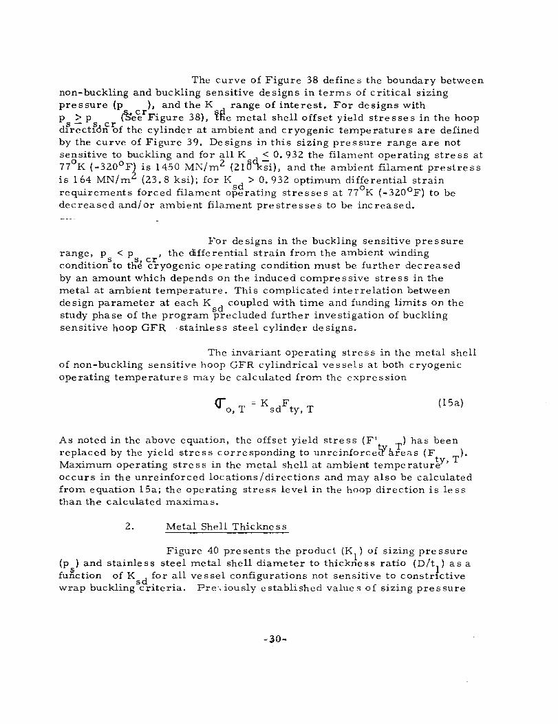
The curve of Figure 38 define s the boundary between non-buckling and buckling sensitive designs in terms of critical sizing pressure (p ), and the K range of interest. For designs with p > p &e~t Figure 38), ~Re metal shell offset yield stre sse s in the hoop dfr;ctfdtf1>f the cylinder at ambient and cryogenic temperatures are defined by the curve of Figure 39. De signs in this sizing pres sure range are not sensitive to buckling and for all K d < 0.932 the filament operating stress at 77
0K (-320 0 F) is 1450 MN/m2 (210K-;i), and the ambient filament prestress
is 164 MN/m2 (23.8 ksi); for K d > 0.932 optimum differential strain requirements forced filament o~e rating stre s se s at 77
0K (-320 0 F) to be
decreased and/or ambient filament prestresses to be increased.
For de signs in the buckling sensitive pre s sure range, p < p ,the differential strain from the ambient winding
d ·· s s, cr . . d' . b f d d con lhon to the cryogenlc operahng con lhon must e urther ecrease by an amount which depends On the induced compressive stress in the metal at ambient temperature. This complicated interrelation between design parameter at each K d coupled with time and funding limits on the study phase of the program precluded further inve stigation of buckling sensitive hoop GFR "stainle ss steel cylinder de signs.
The invariant operating strc s s in the metal shell of non-buckling sensitive hoop GFR cylindrical ve s sel s at both cryogenic operating temperatures may be calculated from the expression
( 15a)
As noted in the above equation, the offset yield stress (F ' ) has been replaced by the yield stre s s corre sponding to unreinforceWafeas (F ). Maximum operating stre s s in the metal shell at ambient tempe ratur~Y' T occurs in the unreinforced locations/directions and may also be calculated from equation l5a; the operating stress level in the hoop direction is less than the calculated maximas.
2. Metal Shell Thickness
Figure 40 pre sents the product (Kl
) of slzlng pre ssure (p ) and stainless steel metal shell diameter to thickness ratio (D/t
1) as a
fuEction of K d for all vessel configurations not sensitive to constnctive wrap bucklingScriteria. Pre", iously established value s of sizing pre s sure
-30-
and ve ssel diameter permit the metal shell thickne ss to be calculated from the expre s sion
(l6)
Completely overwrapped spheres and oblate spheroids are not constrictive wrap buckling stre s s sensitive in the study operating pre s sure range, GFR stainle ss steel shells with the se shape s are de signed so that compre s si ve stre s se s at zero pre ssure after sizing do not exceed the compre s sion allowable s at the ope rating tempe ratures. The transition metal shell diamete r to thickne ss ratio, where constrictive wrap buckling strength controls the design, is 4240 for s~heres and 3396 for oblate sphero~ds; both o.f these ratios corres.i:'ond to operahng pressures less than 690 N/cm (l000 pSl).
a. Completely GFR Cylindrical Ve s sels
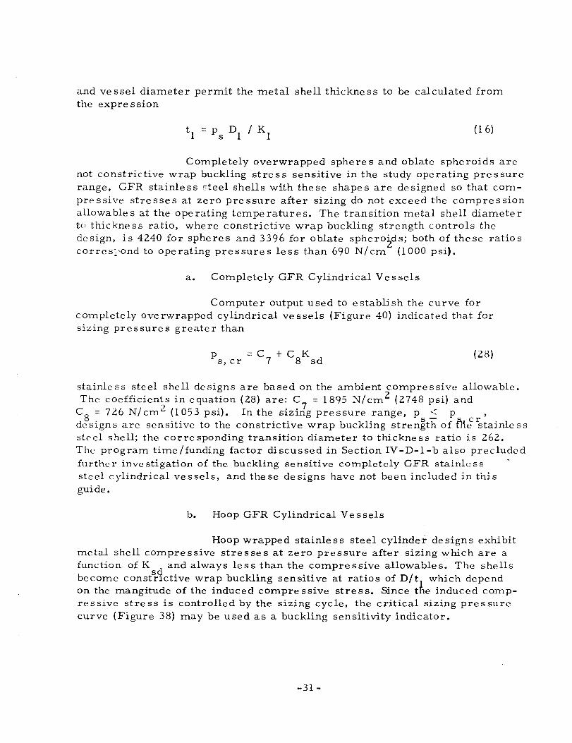
Computer output used to establish the curve for completely ove rwrapped cylindrical ve ssels (Figure 40) indicated that for sizing pre s sure s greate r than
(28)
stainless steel shell designs are based on the ambient compressive allowable. The coefficients in equation (28) are: C = 1895 N/cm 2 (2748 psi) and
C8
= 726 N/cm 2 (1053 psi). In the siziJg pressure range, p -< p , de signs are sensitive to the constrictive wrap buckling strength" of raf rstainle s s steel shell; the corre sponding transition diameter to thickne s s ratio is 262. The program time / funding factor di scussed in Section IV -D-l-b also preclude d furthc r inve stigation of the buckling sensitive cOITlpletcly GFR stainle s s steel cylindrical ve s sels, and the se de signs have not been included in thi s guide.
b. Hoop GFR Cylindrical Vessels
Hoop wrapped stainle s s steel cylinder de signs exhibit metal shell compressive stresses at zero pressure after sizing which are a function of K and always less than the compressive allowables. The shells become const~1ctive wrap buckling sensitive at ratios of D/t
l which depend
on the ITlangitude of the induced compressive stress. Since the induced compressive stress is controlled by the sizing cycle, the critical sizing pressure curve (Figure 38) may be used as a buckling sensitivity indicator.
-31-

3. Longitudinal Composite Thickness
Value s of longitudinal filament thickne s s to metal shell thickness ratio (K ) for GFR stainless steel spheres are presented in Figure 41 as a fun~tion of K . The corresponding uniform composite h · k .. b h sd . t 1C ness 1S glven y t e express10n
t = 2K tl/p c e vg
(17)
Figure 42 pre sents K for G FR oblate sphe roids and compre ssive allowable de signs of comp1etely overwrapped cylindrical vessels. The longitudinal composite thickness at the equator of the oblate spheroid and in the cylindrical section of the completely GFR cylindrical vessel is given by the expression
2 t = K t I (p cos ()( 0) c e 1 vg
(18 )
where,
p vg
= 0.673
Db /D = 0.2
tan 0( = (Dbl D) I (LID) 0
4. Hoop Compo site Thickness
F:; gure 43 pre sents hoop filament thickne ss to metal shell thickness ratios (~) as a function of K for both types of GFR cylindrical vessels. For hoop GFR cylindrical vei~ls, a discontinuity occurs in the curve at a value of K = 0.955. The change in slope of the curve at this point is a direct resulf of the decrease in filament operating stress discussed in Section IV -D-l- b.
Hoop composite thickness for both types of cylindrical ve ssels may be calculated from the expre ssion
(19)
independent of the LID ratio.
-32-

5. Vessel Burst Pressure
Analysis of stressl strain output from the computer indicated the primary mode of failure for completely GFR stainle ss steel ve s sel sis fracture of the longitudinal filaments. Bur st to operating pre s sure ratios (K ), based on this failure mode, for completely GFR stainless steel ve s sel s n~t sensitive to buckling are pre sented in Figure s 44, 45, and 46 for operating temperatures of 297 0 K (+75 0 F), 77 0 K (-320 0 F), and 20 0 K (-423 0 F), r.' specti vely.
Figure 47 presents burst to operating pressure ratios for compressive yield designs of ambient and cryogenic operated hoop GFR cylindrical vessels. Modes of failure are also defined in the figure for each operating temperature.
The curves may be used to establish vessel burst pressure for all configurations and operating conditions from the expre s sion
(20)
6. Vessel Performance and Weight
Performance factor s (K ) for ambient operated GFR stainless steel vessels are presented in FigGre 48 for each configuration as a function of K . Similar plots for the 770 K (-320 o F) and 20 0 K (-423 0 F) operating temper1t?lrcs are presented in Figures 49 and 50, respectively.
Bands of performance, are shown for both types of GFR cylindrical vessels, since the performance of these vessels depends on the vessel length to diameter ratio (LID). Lower bounds of cylinder performance are based on LID = 1.0 for completely GFR cylinders and L/D = 2.0 for hoop GFR cylinder; both lower bound values were established from practical considerations.
Weights of vessels (excluding bosses, attachments, and fluids) with specific volume and operating requirements may be established from the curve s by the expre s sion
W = P TV/K 0, w
(21 )
-33-

E. SAMPLE DESIGNS
The design equations and curves presented in this report are used here to illustrate the procedure for preliminary design of GFR metal tanks.
De sign No. 1 (Buckling Sensitive)
In addition to the basic study de sign criteria, the following hypothetical de sign requirements are as sumed:
Operating pressure at 297 0 K (+75 0 F)
Required volume
Available tank space
Metal shell material
Metal shell maximum operating stre s s to sizing stre s s ratio {hypothetically derived from fracture m "chanic s data}
965 N/cm2
(1400 psi)
1. 22 m (4. 0 ft) x 1. 22 m ( 4. 0 ft) x 6. 10m (2. O. 0 ft)
Inconel X-750
0,80
Volume and envelope dimensions indicate the configuration should be cylindrical {it could be stacked spheres} and efficiency considerations lead to a completely GFR pattern. For a volume of 2.83 m 3 (l00 ft3), Equation 12 is used to arrive at a diameter, D = 0.91 m (3 ft), and an overall vessel length, L = 4.55 M (15 it) (L/D = 5), which meet the envelope requirements.
With the above information, the equations and curve s of Section IV -C are u sed to e stabli sh the ve s sel de sign parameter s. The table below summarize s re sulting data and reference s the governing equation or figure.
-34-

Sizing pressure
Metal shdl sizing stress
Metal shell maximum operating stre s s
Buckling sensitivity sizing pressure
Minimum allowable sizing pressure
Metal shdl thickness
Longitudinal composite thickne s s
Hoop composite thickne s s
Arnbient burst pressure
Pcrformanc l' factor
Parameter
K P
(f = F' sty, A
((f ) O,max A
Ps,er
p . S, mIn
Value SI Units
0.80
1. 250
1210 N/cm 2
890 MN/m 2
712 MN/m 2
1270 N/cm 2
10BON/cm 2
US Units Data Source
0.80 Given
1.250 Figure 18
1750 psi Equation 13
129.1ksi Figure 20
103.3 ksi Equation 14
1840 psi Equation ")? ......
1560 psi Equation 23
K1 - not applicable; p < p indicates design is b k1
' .. s s, cr uc Ing sensItlve
D/t1
317. 5 317. <; Figure 24
tl 0.287 cm o. 113 inch direct calculation
K 0.0475 0.0475 Equation 24 c
t O. 020 cm O. 008 inch F:quation Itj e
K 0.694 0" 694 Eqllatjon ~') h
t hc
0.296cm 0.117 inch Equ;ltion 19
K b
1. 360 1.360 Equation) 1
1310 N/ em 2
Pb,A 1900 psi Equation 20
K 67 J / g 0.27 x 10 6
Figu rc ' ) )~
\V in-lb/1b
W 407 kg 896 Ibs Equation 21
-35-

Analysis of the above design details for this hypothetical example indicates the longitudinal composite thickness (t ) is quite small, if not impractical for this size tank. Thus, a better cfi=oice for this application might have been a hoop GFR cylindrical vessel. Other comments could be made about the specific details, but this would serve no purpose since the assumed criteria was chosen to maximize use of general procedure s.
De sign No. 2 (Not Sensitive to Buckling)
In order to show a typical de sign path for a non-buckling sensitive de sig'l, the following hypothetical requirements are assumed:
Operating Pressure at 77 0 K (-320o F)
Required Shape
Maximum Diameter
Metal Shell Material
Metal Shell Maximum Operating to Sizing St re s s Ratio
2 . 2070 N/ cm (3000 pSl)
Sphere
0.914 m (3 ft)
22l9-T62 Aluminum
0.70
Based on the required diameter, Equation 9 is used to arrive at a volume of 0.40 m 3 (14 ft 3 ). With the above information, the equations and curves of Section IV-B are used to establish the vessel design parameters swnmarized in the following table.
-36-
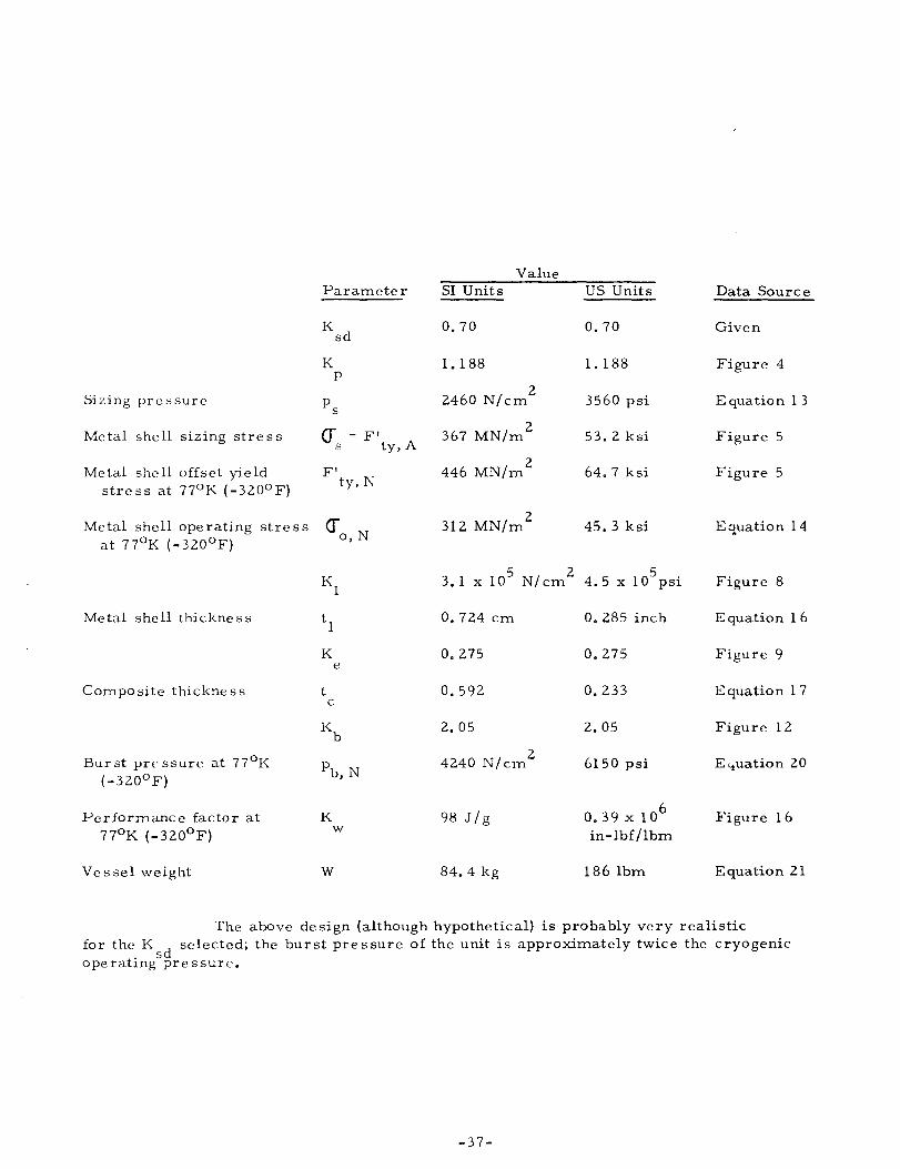
Sizing pr e s sure
Metal shell sizing stress
Metal shell offset yield stress at 770 K (-320°F)
Metal shell operating stress at 77 0 K (-320°F)
Metal shell thickne ss
Compo site thickne s s
Bur st pre ssure at 77 0 K ( -320°F)
Performance factor at 770 K (-320°F)
Ve s sel weight
Parameter
K sd
K p
(f =: F' sty, A
F' ty, N
<r 0, N
K e
t c
K w
w
Value S1 Units
0.70
1.188
2 2460 N/cm
367 MN/m2
446 MN/m2
312 MN/m2
US Units
0.70
1. 188
3560 psi
53.2 ksi
64. 7 ksi
45.3 ksi
5 2 5 3.lx10 N/cm 4.5xlOpsi
0.724 cm
0.275
0.592
2.05
2 4240 N/cm
98 J / g
84.4 kg
0.285 inch
0.275
0.233
2.05
6150 psi
6 0.39 x 10 in-lbf/lbm
186 Ibm
Data Source
Given
Figure 4
Equation 13
Figure 5
Figure 5
Equation 14
Figure 8
Equation 16
Figure 9
Equation 17
Figure 12
E y'uatio n 20
Figure 16
Equation 21
The above design (although hypothetical) is probably very realistic for the K d selected; the burst pressure of the unit is approximately twice the cryogenic
. 5 operatIng pre ssurc.
-37-

V. SAFELIFE VERSUS BURST FACTOR OF SAFETY DESIGNS
As noted earlier, ves sel criteria for this Guide are based on safelife de sign. Complementing fracture data generated under other tasks of the program permit selection of appropriate K d value s for ve ssel service cycle requirements. Vessel designs develo~ed for values of K down to
sd 0.70 generally had burst factors of safety less than 2. O.
Subsequent to preparation of most material in this Guide, Space Shuttle requirements in Reference 1 specified that pressure vessels other than major propellant tanks should have a bur st factor of.? 2.0. De signing for a minimum burst factor of safety 2: 2.0, as well as safelife, introduces a new criterion which increases thicknesses, and increases reliability of the vessels. This is an important and quite significant situation, working in favor of GFR metal vessel applications to the Space Shuttle as follows:
(a) The required burst factor of safety of.? 2.0 re suIts in an "overdesigned" GFR metal tank compared to current best estimates of the required metal shell operating stress ratio, K sd' for safelife de sign.
(b) Conventional metal tanks also have a factor of safety of 2: 2.0 so that the inherent weight saving of GFR metal tanks is not biased by any lower factor of safety for the metal tank.
(c) The required GFR metal tank "overdesign" for burst pressure results in a reduction in the metal and/or filament overwrap stre SSe s from their maximum safe oper,"Iting value s at the vessel operating pressure.
(d) Since the lightest vessel is the one with the least metal, weight minimization dictateS making the liner as thin as possible consistent with GFR metal tank criteria. If this is done in conjunction with a 2.0 burst factor of safety, composite tank weight saving compared with homogeneous metal tanks will increase over the performance factors presented in this Guide.
-38-

VI. CONCLUDING REMARKS
A. The information contained in this de sign guide permit s rapid preliminary sizing of GFR metal tanks, including the determination of value s for proof pre s sure, metal shell and compo site overwrap thickne sse s, ve s sel diameter and length, and weight for given value s of (1) internal volume, (2) operating pressure, (3) operating temperature, and (4) typical Space Shuttle service cycle requirements.
B. During the conduct of the study the three singular values of metal shell operating to sizing stress ratio (K d)' dictated by study criteria, were increased to cover the entire range of K sd between 0.70 and 1.00. This generalization provide s GFR tank de sign scapability for any K value, within this range, which may come from fracture mechanics consi~ration.
C. Pre s sure ve ssel operating performance factor s are high compared with homogeneous metal tanks. Generally, the GFR stainle s s steel ve ssels exhibit the highe st performance followed by GFR aluminum and GFR Inconel ve ssels. At ambient operating temperature the GFR sphere is (l) 20 to 25% more efficient than a long completely overwrapped cylinder, (2) 25 to 30% more efficient than a GFR oblate spheroid, and (3) 30 to 40% more efficient than a long hoop GFR cylindrical vessel. At cryogenic operating temperature s, a smaller efficiency spread between configurations exists.
D. Although performance is a major consideration, selection of the metal material should be based on analysis of fracture data and suitability of the metal shell for the service temperature range and contained fluid.
E. The operating pressure range considered in this design guide was 690 to 2760 N/ cm2 (l000 to 4000 psi), and care should be exercised in using the guide to establish de signs outside this pre ssure range. Many of the desi~n variable s appear to be constant at ope rating pre ssure s above 2760 N/cm (4000 psi), but in many cases "thick wall" effects lead to non-conservative estimates.
-39-

I ~ o I
TABLE 1
MATERlAL PROPERTIES USED IN PARAMETRIC STUDY (Reference 3, except as noted)
Material
Inconel X-750 (STA)
Aluminum 2219-T62
Cryoformed 301 Stainle s s Steel (b)
Glas s-Fjlaments
(a) Reference 8 (b) Reference 7
Df'nsitv
g/cm 3
lbm/in3
8.30 0.300
2.82 0.102
7.47 0.270
1.99(c) 0.072(c)
(c) Composite value based on P = 0.673 (d) Reference 4 vg
Coefficient of Thermal Expansicw.
lnl lnl l'
~/oK x 106
8.98 4.99
16.05 8.915
8.26 4.59
3.62 2.01 --~ -~----------.----
Tensile Yield StrenQ:th
MN/m 2
ksi
814 118
293 42.5
1190 (a) 1 72 (a)
I I I i - I -I 1 1
Derivative of yield strength with re spect to temperature
N/cm2
/o
K . 0
pSI/ F
-74.6 - 60.1
-36. 1 -29.1
-94. 3 (a) _76.0(a)
- --
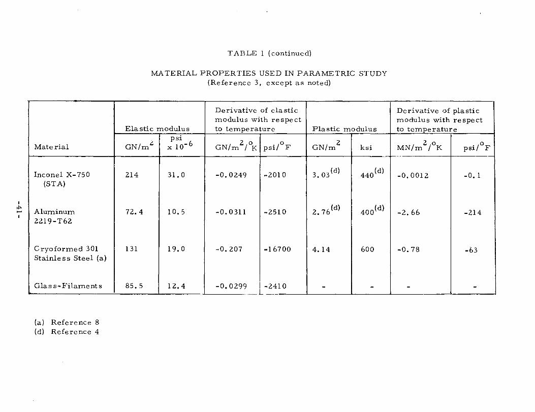
I ~ ..I
Material
Inconel X-750 (STA)
Aluminum 2219-T62
Cryoformed 301 Stainle s s Steel (a)
Glas s-Filaments
(a) Reference 8 (d) Reference 4
TABLE 1 (continued)
MATERIAL PROPERTIES USED IN PARAMETRIC STUDY (Reference 3, except as noted)
Derivative of elastic modulus with re spe ct
Elastic modulus to temperature Plastic modulus psi
2 0 2 GN/m
L. x 10- 6 0 GN/m GN/m / K psi/ F ksi
214 31. 0 -0.0249 -2010 3.03 (d) 440 (d)
72.4 10.5 -0.0311 -2510 2.76 (d) 400(d)
131 19.0 -0.207 -16700 4.14 600
85.5 12.4 -0.0299 I -2410 - ---- - -- I -
Derivative of plastic modulus with respect to temperature
MN/m2
/o
K psi/oF ---j
I
-0.0012 -0. 1
-2.66 -214
-0.78 -63
- ---- -
I
*" N I
Material
Inconel X-750 (STA)
Aluminum 2219-T62
Cryoformed 301 Stainle s s Steel (a)
Glas s-Filaments (a)
(a) Refe~ence 8 (b) Reference 7
TABLE 1 (continued)
MATERIAL PROPERTIES USED IN PARAMETRIC STUDY (Reference 3, except as noted)
- -----.-----
Derivative of Poisson's ratio Maximum allowable operating stress
Poisson's with respect to (Compressive ill metal, tensile in filaments) ratio temperature 297
uF (7So F) 770 K ( _320-uF ) 200 K
Dimensionle s s Dimensionle s s MN/m 2
ksi MN/m 2
ksi MN/m 2
0.290 0.0 745 108 889 129 931
0.325 -0.2005 x 10 -4
273 39.6 342 49.6 360
0.290(b) O.O(b) 772 112 903 131 938
- - 1380 200 1720 250 1720
I
( - 423 l:YF )
ksi
135
52.2
136
250

I ~ v.> I
Material
Incone1 X-750 (STA)
Aluminum 2219-T62
Cryoformed 301 Stainle s s Steel (a)
G1as s-Fi1aments (d)
(a) Reference 8 (d) Reference 4
TABLE 1 (continued)
MA TERlAL PROPER TIES USED IN PARAMETRIC STUDY (Reference 3, except as noted)
Ultimate Strength
29i)K 1750F) 770
K ( _320°F) MN/mC, ksi MN/mt::. ksi
1200 174 1480 214
407 59 538 78
1410 204 1930 280
2280 330 2840 412 - ---- --------- -- -------- --- ---- -- -- -
-
200
K (-423°F) MN/mt.. ksi
1610 234
634 92
2030 295
I I
2840 412 I I
I

IAt IQt IAt STRESS-STRAIN CURVE FOR METAL SHELL - FIRST CYCLE 1St MAXIMUM STRA!N REQUIR~D OF COM?mt SHELL - FIRST CYCLE ICt STRESS-STRAIN CURVE FOR GLASS-FI BER SHELL - ALL CYCLES (Dt STRESS-STRAIN CURVE FOR N'ETAL SHELL-UNLOADING FR'JM FIRST CYCLE
ell II II ti (E) COMPRESSIVE STRESS ACHIEVED IN METAL SHEll WHEN VESSEL PRESSURE IS ZERO AFTER STRI'.IN TO (A)
t I 10/ I L
(F) TENSION STRESS IN GLASS FIBER SHELL THAT BALANCES COMPRESSION STRESS (E) IN METAL SHELL
I IG) RESIDUAL STRAIN IN GLASS FIBER AND METAL SHELLS WHEN VESS~L
PRESSURE IS ZERO AF1ER STRAIN TO (A)
VI
J (H) OPERATING STRESS IN GLASS FIBER SHELL - All CYCLES SUBSEQUENT
VI TO THE FI RST ..., c::
(J) OPERATING STRESS IN N'ETAl SHEll- ALL CYCLES SUBSEQUE\fT TO FIRST >-V>
~ (K) OPERATING STRAIN IN GLASS-FISER AND METAL SHELLS - ALL CYCLES
VI SUBSEQUENT TO FIRST z (U STRESS IN GLASS FIBER SHELL FROM WINDING ON RIGID MANDREL :==
(F) (M) STRAIN IN GLASS FlEER SHELL FROM WINDING ON A RIGID MANDREL; ZERO STRAIN POINT OF "'~AL SHEll BEFORE WINDING
~ ! 1M)
I!li) I (KIS) STRAIN (N) STRESS IN GLASS FI BER SHELL AFTER MANDREL REMOVAL WHEN ~ I
I VESSEL PRESSURE IS ZERO
(0) STRAIN IN r.~Al AND GLASS FIBER SHELLS AFTER MANDREL VI (0) I
REMOVAL WHEN VESSEL PRESSURE IS ZERO Vl ...,
(Pt ULTIMATE STRESS OR STRAIN OF GLASS FI BER SHEll 0:: >-V>
I (Q) UlTlMAJt STRESS OR STRAIN OF METAL SHELL WHEN FIlA~NTS FRACTURE ..., (R) ARBITRARY STRAIN POINT IN f~ETAL SHEll AND GLA.SS FIBER SHELL >
Vl BELOW METAL SHELL PROPORTIONAL LIMIT VI I w w:: 0-
~
I 0 u
I I
\'
FIGURE 1: STRESS-STRAIN DIAGRAM FOR GLASS FILAMENT !!!EINFORCED METALLIC SHELL

~ U1
-9-
OBLA TE SPHEROID
q-:, +0': 2
SPHERE I +J
-~2~ t ~ +Aj
-0(1,,\ I ~~""'~/ ~'V'-:'" <:J /' ", /'" y
/' / ,'" 'V ~ ", I "~c,,' I "",', .,.~~
HOOP WRAPPED CYLINDER COMPLETELY OVERWRAPPED CYLINDER
v I
V
FIGURE 2: VESSEL CONFIGURATIONS AND WRAP PATTERNS

SLOPE = EL
REAL CURVE
SLOPE = El VL I ~ e x i l ' -----~! --~~~~--------~@~~~ SYL dt- - - --. /~-- I
~I <C
~I Z! Hi
(/). <C'
~ 01 P::;I
0- f z ~I
Cf)
/ E=:I ~I
Cf) ~ w kll ~I 0::: ~
~I °1 cq
E-<! E-<
~I Zl kl
~ ~I 51 <C
:::1 ...... ~I
~
I I
G STRAIN
FIGURE 3: LINEARIZATION OF METAL SHELL STRESS/STRAIN CURVE

HOOP WRAPPED CYLINDERS 1.4~------------------~------------------r-------------------;
1.3
1.2
K P 1.1 1----~~~3-~
K P
K P
1.0
. 9 .7
1.4
1.3
1.2 ~ ~
.8
_.-
. 9 LO K sd
SPHERES
T = 297°K (75°F) --~---0
--1.1
T - 77°K(-320°F)J --r----0 1.0
. 9
T lOoK (-423°F) 0
I ----=.==:::::
.7 .8 .9 1.0
COMPLETELY OVERWRAPPED CYLINDERS AND OBLATES 1.4 ~-----------------''-------------------r-----------------~
1.3
1.2 ~----------------~~--~~ -----------4----------------
1.1
.9 L-________________ ~ ________________ ~ ________________ ~
• 7 .8 . 9 1.0
FIGURE 4: SIZING PRESSURE REQUIREMENTS FOR AMBIENT AND CRYOGENIC OPERATED GFR 2219-T62 ALUMINUM PRESSURE VESSELS
- 47 -

47o __ --------~--------r_------~68.0
460
66.0
450
440
T = 7r K (- 320 0 F) o
430 62.0
420 -C\I
S 60.0 -Z -::E .....
410 00 - ~ -~~ ~~ ~ ~
400 58.0
390
56.0
380
54.0 370
360 ~--------~--------~------~52.0
• ? .8 . 9 1.0
FIGURE 5: METAL SHELL OFFSET YIELD STRENGTH AT AMBIENT AND CRYOGENIC TEMPERATURE FOR SIZED GFR 2219-T62 ALUMINUM SPHERES
- 48 -

470 68.0
460
66.0 T = 200K (-423° F)
o 450
400 58.0
390
56.0
380
370 54.0
52.0
.7 .8 . 9 1.0
Ksd
FIGURE 6: METAL SHELL OFFSET YIELD STRENGTH AT AMBIENT AND CRYOGENIC TEMPERATURE FOR SIZED COMPLETELY GFR 2219-T62 ALUMINUM OBLA TE SPHEROIDS AND CY LINDRICA L VESSELS
- 49 -
-C\l
S 'Z :;E --~ ~
r-------~~------~--------164.0
420 T = 20 0 K o
(_42.3° F) 60.0
390
Unreinforced Metal
F~y' T 360 Condition T 52.0 2
ksi MN/m
A 42.5 293
N 54.0 372
330 48.0
297°K
(75° F)
300 44.0
40 .. 0 270~--------~--------~--------~
• 7 .8
K = sd
. 9 1.0
-..... til ,!o:! --~ ~
FIGURE 7: METAL SHELL OFFSET YIELD STRENGTH A T AMBIENT AND CROYGENIC TE,MPERATURE FOR SIZED HOOP GFR 2219-T62 ALUMINUM CYLINDERS
- 50 -

3.4 X 10⁵
3.0
2.5
2.0
2 K1 (N/cm )
1.5
1.0
I -f-
f-
f-
f-
l-
l-
l-
I--
I-
l-
I--
I-
I-
~
I-
I-
-I-
-
-
I-
t:a-
I-
l-
I-
I-
. 7 .8
-
-
-SPHERES
l i
--l 4 i I I
-4
~ -
\- OBLATES
- 3
-
-
-
-COMPLETELY
OVERWRA PPEl: 2 CYLINDERS
-
'- HOOP WRA PPED -CYLINDERS
.9
-
-
1 1.0
FIGURE 8: METAL SHELL THICKNESS PARAMETER FOR GFR 2219-T62 ALUMINUM PRESSURE VESSELS
- 51 -
K1 (psi)

.030
.020
K e
.010
.400
.300
K e
• 7
~
.208. 7
.200
.100
K e
.000 • 7
COMPLETELY OVERWRAPPED CYLINDERS
.8 .9
SPHERES
.8 . 9
OBLATES
. 8 . 9
FIGURE 9: LONGITUDINAL FILAMENT TlllCKNESS PARAMETER FOR COMPLETELY GFR 2219-T62 ALUMINUM PRESSURE VESSELS
- 52 -
1.0
-
1.0
1.0

.50 ...--------..------,------,
. 40 1--------40-----+-------1
COMPLETELY OVERWRAPPED CYLINDERS
.30 1-------+---
• 2 0 I------~------t-~'---------t
.10 HOOP WRAPPED CYLINDERS
.00 '--___ ---1. ____ --'-____ ......1
.7 .8 .9 1.0
FIGURE 10: HOOP FILAMENT THICKNESS PARAMETER FOR GFR 2219-T62 ALUMINUM CYLINDRICAL VESSELS
- 53 -

1.9
1.8
1.7
1.6
1.5
1.4
1.3
1.2
1.1
FAILURE MODE:
.7
FRACTURE OF LONGITUD INAL FILAMENTS F tuf = 2280 MN I rn2
(330 ksi)
- OBLATES
COMPLETELY OVERWRAPPED CYLINDERS
.8 . 9 1.0
FIGURE 11: AMBIENT BURST PRESSURE FACTORS FOR COMPLETELY GFR 2219-T62 ALUMINUM PRESSURE VESSELS
- 54 -

2.2
FAILURE MODE:
2.1
2.0
1.9
1.8
1.7
1.6
FRACTUR E OF LONGITUDINA FILAMENTS F
tuf = 2840 MN/m2 (412 ksi)
/ ,- SPHERES
COMPLETELY OVERWRAPPED
1.5 CYLINDERS
1. 4 .7 .8 .9 1.0
FIGURE 12: BURST PRESSURE FACTORS AT 77°K (-320°F) FOR COMPLETELY GFR 2219-T62 ALUMINUM PRESSURE VESSELS
- 55 -

2.3 --------~r_------~--------, FAILURE MODE:
2.2
FRACTURE OF LONGITUDINAL FILAMENTS
F f = 2840 MN/m2 (412 ksi) tu
2.1 ~~-----4--------~------~
2. 0 I--------I~--f----+------__i
1.9
1.8
1.7
COMPLETELY 1. 6 OVERWRAPPED-~.t---------t
CYLINDERS
1. 5 • 7 .8 . 9 1.0
FIGURE 13: BURST PRESSURE FACTORS AT lOoK (-423 0 F) FOR COMPLETELY GFR 2219-T62 ALUMINUM PRESSURE VESSELS
- 56 -
2.1 -
2.0
1.9
1.8
1.7
1.6
1.5
1.4
Filaments
Metal
1.3 • 7
Filament Fracture
Filament Fracture "'-1---1
Filament ..... J----I
Fracture Metal Fracture
+--------- - -- ---
Metal Fracture
-----~-~--------
Ultimate Strength
297°K ~75°FJ
MN/m (ksi)
2280 330
410 59
.8
77°K (-320°F)
MN/m2 Jksi)
2840 412
540 78
.9
200K (-423 OF)
MN /rr? ~k~i} 2840 412
630 92
1.0
FIGURE 14: AMBIENT AND CRYOGENIC BURST PRESSURE FACTORS FOR HOOP GFR 2219-T62 ALUMINUM PRESSURE VESSELS
- 57 -

125 .50 X 106
100 .40
K K
w w (in-lb/lb)
(J / g)
75 .30
50 ~--------~--------~--------~ .20 . 7 .8 . 9 1.0
K sd
Completely Overwrapped Cylinders ( L/D= 00 )
Comp1et ely Overwrapped Cylinders ( L/ D= 1 ) Hoop Wrapped Cylinders (L/ D= 00) Hoop Wrapped Cylinders (L/D= 2)
FIGURE 15: PERFORMANCE FACTOR FOR AMBIENT OPERATED GFR 2219-T62 ALUMINUM PRESSURE VESSELS
- 58 -
125 6
.50 X 10
100 .40
K w
K w (in-lb/lb)
(J / g)
75 .30
FIGURE 16:
50 ~--------~--------~--------~ .20 1.0 .7 .8 . 9
Completely Overwrapped Cylinders (L/ D= QO) Completely Overwrapped Cylinders (L/ D= 1) Hoop Wrapped Cylinders (L/ D=cO ) Hoop Wrapped Cylinders (L/ D=2)
PERFORMANCE FACTORS FOR GFR 22l9-T62 ALUMINUM VESSELS OPERATED AT 77°K (_320° F)
- 59 -

125 .50 X 106
SPHERES
100 .40
K w K
w (J / g)
(in-lb/lb)
75
50 • 7 . 8 .9
.30
.20 1.0
Completely Overwrapped Cylinders (L/ D= 00 )
Completely Overwrapped Cylinders (L/ D= 1) Hoop Wrapped Cylinders (L/D= (0) Hoop Wrapped Cylinders (L/ D= 2)
FIGURE 17: PERFORMANCE FACTORS FOR GFR 2219-T62 ALUlvUNUM VESSELS OPERATED AT 200K (-423°F)
- 60 -

K P
K P
K P
1.4
1.3
1.2
1.1
1.0
.9
1.4
1.3
1.2
1.1
1.n
.9
1.4
1.3
1.2
1.1
1.0
.9
HOOP WRAPPED CYLINDERS
.7 .8 .9
.7
.7
SPHERES
.8 .9
COMPLETELY OVERWRAPPED CYLINDERS AND OBLATES
.8 .9
FIGURE 18: SIZING PRESSURE REQUIREMENTS FOR AMBIENT AND CRYOGENIC OPERATED GFR INCONEL X-750 PRESSURE
VESSELS
-.61 -
1.0
1.1'
1.0

1120 r------"T'-----O;'-r------, 162. 0
l100~r-~-l-t----4----J - 158.0
T = 20 0 K (-423°F) o 10801-
- 154.0
I060r-T---t-----+ ___ J
l T ~ 77"K (-320~FJ o 1040 -
- 150.0
1020 ~
- 146.0
~ -S 1000 f- ..... 00
'Z ~ -~ >. -~ - 142.0 ~
-~ -
980 t-~
960 t-- 138.0
940 I-
- 134.0 920 f-
9001-
• 7 .8 .9 1.0
FIGURE 19: METAL SHELL OFFSET YIELD STRENGTH AT AMBIENT AND CRYOGENIC TEMPERATURE FOR SIZED GFR INCONEL X-750 SPHERES
- 62 -
1120 162.0
-- --1100 f- -T = 200K (-423° F) -
0
158.0
1080 f-
1--- - 154.0 1060 f-
-T = 77°K (-320° F)
0
1040 f-
- 150.0
1020 -
- - 146.0 C'.l s 'Z 1000
~ --.e-~ 980
f-
- -
-...... rJl ,.!t! --.e-~
142.0
960 -- 138.0
940 f-
- 134.0 920 f-
l-
f To= 297°K (75°F)
-...... 130.0 900
-• 7 .8 . 9 1.0
Ksd
FIGURE 20: METAL SHELL OFFSET YIELD STRENGTH AT AMBIENT AND CRYOGENIC TEMPERATURE FOR SIZED COMPLETELY GFR INCONEL X-750 OBLATE SPHEROIDS AND CY LINDRICA L VESSELS
- 63 -
--
.7
Buckling sensitivity boundary, p = p s s, cr
CJof
= l380 MN/m2
,(164 MN/m2 ~ CJ
wf !: 666 MN/m2).
2 CJwf = 666 MN/m, CJ
o£ as noted.
Hoop sizing stres s les s than yield,
/ / /
/// // /
.8
/ ./ ./
/ / /
/ / / /
/ / ,/
/ / /
CJof= l380 MN/m2
(200 ksi)
I CJof = 1170 MN 1m2
(170 ksi)
I CJ of = 1030 MN 1m
2 (150 ksi)
.9
FIGURE 21: BUCKLING SENSITIVITY INDICATOR FOR HOOP GFR INCONEL X-750 PRESSURE VESSELS
- 64 -
-300'U; 0. -
rJl ~ .. Q)
~ rJl rJl Q) ~ ~
~ ....... N .......
C'I.l
1200~ Q) .......
...a
~
1100
1.0

-C\l
~ ::a .......
-< -~ ~
UNREINFORCED META L
FtyA
= 814 MN/m2 (118 ksi)
r------,...-----r----~125. 0
860
850
840
Designs not sensitive to buckling.
-v /-~ Oaf= 1030 MN/m
124.0
123.0
122.0
121. 0
120.0
820 119.0
.7 .8 .9
Ksd = [ 00 /Fty JA
-.,...., rJ)
~ ....... < -~ ~
FIGURE 22A: METAL SHELL OFFSET YIELD STRENGTH AT AMBIENT TEMPERATURE FOR SIZED HOOP GFR
INCONEL X-750 CYLINDERS
- 65 -
-C\I
~ ~ '-"
Z
-~ ~
UNREINFOR CED META L
F N = 977 MN/rn2
(141. 7 ksi) ty
1020------------,-------,148.0
/" 1010
980
Designs not sensitive to buckling.
147.0
146.0
145.0
L---~----~~--~~~---'--~142.0 . 7 .8 . 9 1.0
-....... til ~ '-"
Z -~ ~
FIGURE 22B: METAL SHELL OFFSET YIELD STRENGTH AT LIQUID NITROGEN TEMPERATURE FOR SIZED HOOP
GFR INCONEL X-750 CYLINDERS
- 66 -

1060
-C"l
~ Z ~ -:r: -~ ~
UNREINFORCED METAL
F = 1019 MN/m.2 (147.9 ksi) tyH
r----------------,155.0
Designs not sensitive to buckling.
154.0
153.0
152.0
151. 0
150.0
149.0
~~~--~-~~-~---~~148.0
. 7 .8 . 9 1.0
-...... til ~ -:r: -~ ~
FIGURE 22C: METAL SHELL OFFSET YIELD STRENGTH AT LIQUID HYDROGEN TE MPERATURE FOR SIZED HOOP
GFR INCONEL X-750 CYLINDERS
- 61 -

2 K
1(N/cm)
K
• 7
.6
• 5
.4
.3
,-----,-----.,...------,1.2 x 106
.7 .8
I 1.1 SPHERES
I ~1.0
.9
.8
Kl (psi)
OBLATES
COMPLETELY OVERWRAPPED
o 7
CYLINDERS .6
.9
• 5
.4 1.0
Ksd & 1 Valid for p 2: p • s s,cr
FIGURE 23: METAL SHELL THICKNESS PARAMETER FOR GFR INCONEL X-750 PRESSURE VESSELS
- 68 -

-< ....,
---0 ~
0 .,.., ..., ell H
en en Q)
~ .!<: u
..c ....,
0 .....
H 0"- Q) --0 ....,
Q)
E ell .,..,
"d
...... ...... Q)
..c en
...... ell ...., Q)
~
1 SO J 340
330
320
310 1050
1608
~
Ambient sizing pressure, p (psi) s
Designs
Designs
1700
sensitive to buckling.
non- existant (t = 0 ). C
Ksd = 0.85
Ksd = 0.95
1800
Ksd = 0.75
HOO 1150 1200
Ambient sizing pressure, 2
p (N/cm) s
1250
1
FIGURE 24: METAL SHELL DIAMETER TO THICKNESS RATIOS FOR BUCKLING SENSITIVE COMPLETELY GFR INCONEL X-750 PRESSURE VESSELS
1900
1300

400
-< 390 ...... -Q
~
0 'M ...... (Ij 1-<
380 'f)
(/l
(j)
c:: .-'t: u
.r<
.£: ....,
0 370 -J ...., 0
1-< (j) ..... Q)
6 (Ij
.r<
'U 360
.-<
.-< Q.)
.£: 'f)
(Ij ...... Q.)
350 ..... ~
340
1000 1100
Sizing pres sure (psi)
1200
d~, f I ~ ........
'-...
'\ "" ~ 'Z
........ ........
H & Buckling sensitive designs.
b Hoop sizing stress les s
l ______ than yield.
Ksd = 0.75
700 750 800 850 ~. . 2) ::>lz1ng pressure, P (N/crn
s
l300 1400 -------T~~-· •
900 950
FIGURE 25: METAL SHELL DIAMETER TO THICKNESS RATIOS FOR BUCKLING
SENSITIVE HOOP GFR INCONEL X-750 PRESSURE VESSELS

K e
.9
.8
.7
.6
• 5
.4
· 3
.2
· 1
--.--~-.- --._----- I-------~--- --- -----~-
--: I I
-- - -- -----I
~PHERES
---! ~ i
~- -- I ----I I
! I !
r-- 1 I
i
I ._-" I --
l\BLATES
~
I--"" ------
~
COMPLETELY OVERWRAPPED CYLINDERS -( Ps~Ps cr) ,
----.-.-.-
.7 .8 . 9 1.0
FIGURE 26: LONGITUDINAL FILAMENT THICKNESS PARAMETER FOR COMPLETELY GFR INCONEL X-750
PRESSURE VESSELS
0- 71 -

Notes:
1. Curves valid for all Ps~ Ps,cr .
~ Completely overwrapped cylindrical vessels.
& Hoop wrapped cylinders .
• 9
· 8
· 7
.6
.5
.4
· 3 . 7 .8 .9 1.0
FIGURE 27: HOOP FILAMENT THICKNESS PARAMETER FOR GFR INCONEL X-750 CYLINDRICAL VESSELS
- 72 -

1.9
1.8
1.7
1.6
1.5
1.4
1.3
1.2
Failure mode: Filament fracture
F = 2280 MN/m2 (330 ksi) tuf
HOOP WRAPPED CYLINDERS
COMPLETELY OVERWRAPPED CYLINDERS
1. 1 . 7 .8 . 9 1.0
FIGURE 28: AMBIENT BURST PRESSURE FACTOR S FOR COMPLETELY GFR INCONEL X-750 PRESSURE
VESSELS
- 73 -

2.0 ~--------~------------------~ I
Failure mode: I FilaITlent fracture 2
F = 2840 MN /ITl (412 ksi) tuf
1.9
SPHERES
1.8 ---~~--~~~------~------~
1.7
1.6
1.5
1.4
1.3
1.2 .7 .8
7
COMPLETELY OVERWRAPPED
CYLINDERS
K sd
.9 1.0
FIGURE 29: BURST PRESSURE FACTORS AT 77°K (-320°F) FOR GFR INCONEL X-7S0 PRESSURE VESSELS
- 74 -
2. 0 .--------,-----r-------,
1.9
1.8
1.7
1.6
1.5
1.4
1.3
1.2
Failure ITlode: I FilaITlent fracture 2
• 7
F f = 2840 MN 1m (412 ksi) tu
.8
SPHERES
HOOP -----. WRAPPED CYLINDERS
COMPLETELY OVERWRAPPED
CYLINDERS
.9 1.0
FIGURE 30: BURST PRESSURE FACTORS AT 20 0 K (-423°F) FOR GFR INCONEL X-750 PRESSURE VESSELS
- 75 -

1.6
1.5
1.4
1.3
Kb
1.2
1.1
1.0
161'0
Notes: 1
&
Ambient sizing pressure, p (psi) s
1800 2000 4000
Failure Mode: Filament frac ture (F tuf = 2280 MN / m 2)
Designs sensitive to buckling.
& Zero longitudinal composite thickness. ~--------====-------------------~~-----------------------~/~--~
~ Ksd = 0.75
---------------------------, r-----~~~------------------------~------------------~!r---~
I I I
I ~ I I
~
1100
Ambient
1200
sizing
Ksd = 0.85
Ksd
=0.95
1300
pressure, p s
2 (N / cm )
1400 2760
FIGURE 31: BURST PRESSURE FACTOR VARIATION FOR BUCKLING SENSITIVE COMPLETELY GFR INCONEL X-750 CYLINDRICAL
PRESSURE VESSELS
- 76-

125
SPHERES
100 ---::I~--I • 4
K w
K w
(in-lb/lb)
(J I g)
75
50 ~--------~--------~~------~ .2 . 7 .8
Ksd • 9 1.0
i COITlpletely Overwrapped Cylinders (LID =00). COITlpletely Overwrapped Cylinders (LID = 1 ). Hoop Overwrapped Cylinders (LID =00 ).
Hoop Overwrapped Cylinders (LI D = 2).
FIGURE 32: PERFORMANCE FACTORS FOR AMBIENT OPERATED GFR INCONEL X-750 PRESSURE VESSELS
- 77 -
125 r------'I"------~---___, . 5 X 10⁶
SPH ERES ---.
100 .4
K w K
w (J I g) (in-lb/lb)
75 ~-----i.3
50 ~-------~------------------~.2 .7 .8 . 9 1.0
t Completely Overwrapped Cylinders (LID = 00 ).
Completely Overwrapped Cylinder s (LI D = 1 ). Hoop Overwrapped Cylinders (L/ D =00). Hoop Overwrapped Cylinders ( L/D= 2 ).
FIGURE 33: PERFORMANCE FACTORS FOR GFR INCONEL X-7S0 VESSELS OPERATED AT 77 oK (-320° F)
- 78 -
125 -----.-------..,r-------, . 5 X 10⁶
SPHERES
100
K K w
w (J I g)
(in-lb lIb)
75 ~~-+------I .3
50 .~7------------------~--------~·2 .8 .9 1.0
K sd
Completely Overwrapped Cylinders (LID =00) . Completely Overwrapped Cylinders (LID = 1). Hoop Overwrapped Cylinders ( LI D= 00). Hoop Overwrapped Cylinder s (LI D = 2).
FIGURE 34: PERFORMANCE FACTORS FOR GFR INCONEL X-750 VESSELS OPERATED AT 2 0 0K (_423° F)
- 79 -

HOOP WRAPPED CYLINDERS 1.6 r-----------------~------------------~----------------~
1.5
1.4
1.3
K P 1. 2
K
K P
1. 1
1.0 T = 200K (-423°F)
~~o~ _____________ ~ __________________ ~_
.9 .~~7~-----------------.~8------~K~s-d----------.~9------------------1~.0
SPHERES 1.4
1.3
1.2
P 1.1
1.0
• 9
1.7
1.6
1.5
1.4
1.3
1.2
1.1
1.0
• 9
. 7
. 7
.8 Ksd
.9 1.0
OBLATES AND COMPLETELY OV ERWRAPPED CYLINDERS
------------ -
- .- ----.---------------+---------=--~~------------
.8
K sd
. 9 1.0
FIGURE 35: SIZING PRESSURE REQUIREMENTS FOR AMBIENT AND CRYOGENIC OPERATED GFR 301 STAINLESS STEEL PRESSURE
VESSELS - 80 -

-~ ~ ::a -~~ ~
1550 ~ ....
1500 !-
""--
1450 ~
1400 ~
1350 ~
1300 I--
I--
r-1250
.7
T = 20 0 K (_423° F) 0
T = 7rK (-320° F) 0
I I Unreinforced Metal
Condition T F'
ty, T
ksi MN/m
A 172.0 1186
N 202.0 1393
H 209.8 1447
J To = 297°K (750
FI
. 8 • 9
2
--
-
--
-
-
-
-
--
220.0
210.0
-..... 00 ~ -200. 0 ~ ~ ~
190.0
180.0 1.0
FIGURE 36: METAL SHELL OFFSET YIELD STRENG TH AT AMBIENT AND CRYOGENIC TEMPERATURE FOR SIZED GFR
301 STAINLESS STEEL SPHERES
- 81 -

1550
220.0 T = 200K (_423° F)
1500 o
1250 ~--------~--------~------~180.0 .7 .8 . 9 1.0
FIGURE 37: METAL SHELL OFFSET YIELD STRENGTH AT AMBIENT AND CRYOGENIC TEMPERATURE FOR SIZED COMPLETELY GFR 301 STAINLESS STEEL OBLATE SPHEROIDS
AND CYLINDRICAL VESSELS
- 82 -
2800
1900
-C\I
S C,.) 2700 ~ -$-I
C,.) .. til
p.. 1800 .. 2600 ~
0 t-t-... < Q)
~ til til Q) $-I ~
~ ...... N ......
00 ...... cd C,.) ..... ... ..... $-I "'--U
1600 ""- 2300
. 7 .8 . 9 1.0 K
sd
FIGURE 38: BUCKLING SENSITIVITY INDICATOR FOR HOOP GFR 301 STAINLESS STEEL PRESSURE VESSELS
- 83 -
...... til
.& $-I C,.) .. til
p..
.. ~ 0 0 C\I M
I ... < Q)
~ til til Q) $-I ~
~ ...... N ......
00 ...... cd C,.) ...... ... ·C u

~--------__ --------~------~220.0
1500r----r--~--------~ __
145oj-__ -,r--+ ________ ~ __ 210.0
T = 77°K (_320° F)
1400 011
Unreinforc ed Metal 200.0
Condition T F t~1 T 2
ksi MN/m - -1350 ..... C\l til
~ A 172.0 1186 ~ -Z N 202.0 1393 -b =a ~ --b ~
H
1300
209.8 1447 190.0
1250 180.0
1200
~--------~--------~------~170.0 .7 .8 .9 1.0
FIGURE 39: METAL SHELL OFFSET YIELD STRENGTH AT AMBIENT AND CRYOGENIC TEMPERATURE FOR SIZED HOOP
GFR 301 STAINLESS STEEL CYLINDERS
- 84 -
14
12
~ (N/cm 2 )
10
8
r---------r---------.---------,24xl05
.7
OBLATES~
COMPLETELY OVERWRAPPED CYLINDERS
HOOP ----, WRAPPED CYLINDERS
P s ~
.8 Ksd
P s,er.
.9
22
20
18
16
Kr ( psi)
14
12
10
8
6xlO5 1.0
FIGURE 40: METAL SHELL THICKNESS PARAMETER FOR GFR 301 STAINLFSS STEEL PRESSURE VESSELS
- 85 -
K e
1.9
I
1.8 ~ - I -- -
I I !
~
I 1.7
i I I
1.6 - --
/ L
/ V
,/
1.5
1.4
1.3
1.2 i .7 .8 .9
FIGURE 41: LONGITUDINAL FILAMENT THICKNESS PARAMETER FOR COMPLETELY GFR 301 STAINLESS STEEL SPHERES
- 86 -
1.0

K e
.9
.8
.7
.6
.5
.4
. 3
. 2
.1
V
~ .7
OBLATES
V I I
/ ~
I
COMPLETELY OVERWRAPPED CYLINDERS
(ps~ ps,cr)
~ ~
.8
K sci
/
/ V
V /'
./ V V
.9 1.0
FIGURE 42: LONGITUDINAL FILAMENT THICKNESS PARAMETER FOR COMPLETELY GFR 301 STAINLESS STEEL OBLATE SPHEROIDS
AND CYLINDRICAL VESSELS
-.87 -

Notes:
1. Curves valid for all p > p s- s,cr.
Completely overwrapped cylindrical vessels.
Hoop wrapped cylinders.
1.8
1.6
1.4
1.2
1.0
.8
.6
.4 .7 .8 .9 1.0
FIGURE 43: HOOP FILAMENT THICKNESS PARAMETER FOR GFR 301 STAINLESS STEEL
CYLINDRICAL VESSELS - 88 -

2.0~--------~--------~---------,
Failure m.ode: Filam.ent frae ture 2 F = 2280 MN/m. (330ksi)
tuf
1.9 ~--------+---------~---------;
1.8
OBLATES
1.7
1.6
SPHERES
1.5
1.4
COMPLETELY 1. 3 OVERWRAPPED --t------~---t
CYLINDERS
1.2 • 7 .8 .9 1.0
FIGURE 44: AMBIENT BURST PRESSURE FACTORS FOR COMPLETELY GFR 301 STAINLESS STEEL
PRESSURE VESSELS
- 89 -

2.0
1.9
1.8
1.7
1.6
1.5
1.4
1.3
1.2 .7
Failure mode:
Filament fracture
F tuf = 2840 MN/m2 (412 ksi)
SPHERES
.8
-COMPLETELY OVERWRAPPED
CYLINDERS
.9 1.0
FIGURE 45: BURST PRESSURE FACTORS AT 77°K (-320°F) FOR COMPLETELY GFR 301 STAINLESS STEEL PRESSURE
VESSELS
- -90 -

2.1
2.0
1.9
1.8
1.7
1.6
1.5
1.4
1.3
Failure mode:
.7
Filament fracture
F f = 2840 MN/m2 (412 ksi) tu
SPHERES
.8
OBLATES
COMPLETELY OVERWRAPPED
CYLINDERS
. 9 1.0
FIGURE 46: BURST PRESSURE FACTORS AT 20 0 K (_42~O F) FOR COMPLETELY GFR 301 STAINLESS
STEEL PRESSURE VESSELS
- 91 -

2.~--------~---------T----------~--------~--------~--------~
1.9
1.8
1. 7 .
1.6
1.5
1.4
FilaIT1ent ..... I--I--II~ Metal
Fracture ____ ~--+ Fractur __ +-________ ~--------~-------
20 0 K (-423°F)
Fild.IT1ent Metal Fracture
--~r-------+---------~--~-~--_r--------~------- -
Metal Fracture
UltiIT1ate strength (MN/ m 2)
297°K 77°K 20 0 K
1. 3 Filaments
Metal
2280
1410
2840
1930
2840
2030
1.2 .7 .8 .9
FIGURE 47: AMBIENT AND CRYOGENIC BURST PRESSURE FACTORS FOR HOOP GFR 301 STAINLESS STEEL PRESSURE
VESSELS
- 9-2 -
1.0

K w
(J / g)
150 _---_-----.,..----~ .6 x 106
SPHERES
125 1---........""c--+--~--_+_----_4 • 5
OBLATES
100
B 6
75 .3 .7 .8
Ksd .9 1.0
Completely Overwrapped Cylinders (LI D= ). Completely Overwrapped Cylinders (LI D= 1). Hoop Wrapped Cylinders (LID = ). Hoop Wrapped Cylinders (LID = 2).
K w
(in-1b/lb)
FIGURE 48: PERFORMANCE FACTORS FOR AMBIENT OPERA TED GFR 301 STAINLESS STEEL PRESSURE VESSELS
- 93 -

K w
(J / g)
150
125
,-----------------.6 x 106
OBLATES
I
SPHERES -
K w
(in-lb/lb)
100
75 ~--------~--------~--------~.3 .7 .8 . 9 1.0
Completely Overwrapped Cylinders (L/ D=OO). Completely Overwrapped Cylinders (L/ D= 1). Hoop Wrapped Cylinders (L/ D=oO). Hoop Wrapped Cylinders (L/D= 2).
FIGURE 49: PERFORMANCE FACTORS FOR GFR 301 STAINLESS STEEL VESSELS OPERATED AT 77°K (-320° F)
- 94 -

K w
(J / g)
150 ~----,.-----r----·-"'.6 X 106
125 -+.t''------i • 5
K w
OBLATES (in-lb/lb)
100 --------~---------;.4
75 L---------~--------~--------_.3 . 7 .8 . 9 1.0
Ksd
Completely Overwrapped Cylinders (L/ D= 00 ).
Completely Overwrapped Cylinders (L/D= 1). Hoop Wrapped Cylinders (L/ D=oO ). Hoop Wrapped Cylinders (L/D= 2).
FIGURE 50: PERFORMANCE FACTORS FOR GFR 301 STAINLESS STEEL VESSELS OPERATED AT 20 0 K (-423°F)
- 95 -

1.
2.
3.
4.
5.
6.
7.
S.
REFERENCES
NASA RFP No. 9-BC421-67-2-40P, Space Shuttle Program, 17 March 1972.
Dorms, F. J. and Landes, R. E.: "Computer Program for the Analysis of Filament-Reinforced Metal-Shell Pressure Vessels II, NASA CR-72124, Aerojet-General Corporation, Rev. May 1972.
Morris, E. E., Dorms, F, J., Landes, R. E. and Campbell, J. W.; "Parametric Study of Glass-Filament-Reinforced Metal Pressure Vessels", NASA CR 54-S55, Aerojet-General Corporation, April 1966.
Morris, E. E.; IIGlass-Fiber-Reinforced Metall ic Tanks for Cryogenic Service", NASA CR-72224, Aerojet-General Corporation, June 1967.
Tiffany, C. F.,; IIFracture Control of Metallic Pressure Vessels ll,
NASA Design Monograph SP-S040.
Buckl ing of Thin-Walled Doubly Curved Shells, NASA Spa:e Vehicle Design Criteria, NASA SP-S032, August 1969.
Gleich, D.; IIDevelopment of a Filament-Overwrapped Cryoformed Metal Pressure Vessel II, NASA CR-72753, January 1971, Arde, Inc.
Bixler, W. D.; IIDeveiopment of a Fracture Control Method for Composite Tanks with Load Sharing Liners II, (Interim Report), NASA CR-12091S, Boeing Aerospace Company, March 1973.
- '96 -