Glass-beads Display: Evaluation for aerial graphics ...
8
Glass-beads Display: Evaluation for aerial graphics rendered by retro-reflective particles Shinnosuke Ando 1 , Kazuki Otao 1 , 2 , and Yoichi Ochiai 1 , 2 1 University of Tsukuba, Ibaraki 3058577, Japan 2 Pixie Dust Technologies, Inc., Tokyo 1010041, Japan [email protected] Abstract. We present a novel method for rendering aerial images using retro- reflective particles. Retro-reflective particles are composed of glass beads that are half-coated with mirror films. They reflect light in different directions without any significant reduction in brightness because the falling particles can rotate in all directions. We evaluate the proposed method through a comparison with conventional aerial screens, such as fog and gas. Keywords: aerial imaging system · projector-screen · retro-reflective particles. 1 Introduction There is a huge demand for aerial screens in the entertainment industry, because they extend the expression of imaging in the air. In addition, this allows images to be displayed in places where physical screens cannot be installed. The fog display, which projects images onto fog screens formed by artificially generated mist, is the most common aerial screen [5]. In the last decade, the study of fog displays has shifted towards human-computer interaction research, and novel applications are constantly being proposed [4, 6, 7]. Fog screens are primarily used for entertainment and production; however, they contain several problems: (1) narrow field of view and image blurring due to Mie scattering, (2) Instability of the display screen due to turbulent flows, and (3) excessively bright projector light. Narrow viewing angles, of magnitude of 20 degrees or less, are also to be noted. In addition, direct light from the projector is often hazardous for children, and limits the design space between the projector and the screen. We propose a novel aerial imaging system using the retro-reflective particle screen. Retro-reflective particles are composed of glass beads that are half-coated with mir- rors [2,8]. They are commonly used in road signs to provide highlights in the dark [3]. Here, the retro-reflective particles are arranged on the road signs to reflect the incident light. We present an alternative application that uses glass beads as the aerial screen for augmented reality (AR). The proposed method possesses some advantages: – Glass-beads display has a wide viewing angle because the incident light enters the retro-reflective particles rotated in all directions.
Transcript of Glass-beads Display: Evaluation for aerial graphics ...

Glass-beads Display: Evaluation for aerial graphicsrendered by retro-reflective particles
Shinnosuke Ando1, Kazuki Otao1,2, and Yoichi Ochiai1,2
1 University of Tsukuba, Ibaraki 3058577, Japan2 Pixie Dust Technologies, Inc., Tokyo 1010041, [email protected]
Abstract. We present a novel method for rendering aerial images using retro-reflective particles. Retro-reflective particles are composed of glass beads that arehalf-coated with mirror films. They reflect light in different directions withoutany significant reduction in brightness because the falling particles can rotatein all directions. We evaluate the proposed method through a comparison withconventional aerial screens, such as fog and gas.
Keywords: aerial imaging system · projector-screen · retro-reflective particles.
1 Introduction
There is a huge demand for aerial screens in the entertainment industry, because theyextend the expression of imaging in the air. In addition, this allows images to be displayedin places where physical screens cannot be installed.
The fog display, which projects images onto fog screens formed by artificiallygenerated mist, is the most common aerial screen [5]. In the last decade, the studyof fog displays has shifted towards human-computer interaction research, and novelapplications are constantly being proposed [4, 6, 7]. Fog screens are primarily used forentertainment and production; however, they contain several problems: (1) narrow fieldof view and image blurring due to Mie scattering, (2) Instability of the display screendue to turbulent flows, and (3) excessively bright projector light. Narrow viewing angles,of magnitude of 20 degrees or less, are also to be noted. In addition, direct light fromthe projector is often hazardous for children, and limits the design space between theprojector and the screen.
We propose a novel aerial imaging system using the retro-reflective particle screen.Retro-reflective particles are composed of glass beads that are half-coated with mir-rors [2, 8]. They are commonly used in road signs to provide highlights in the dark [3].Here, the retro-reflective particles are arranged on the road signs to reflect the incidentlight.
We present an alternative application that uses glass beads as the aerial screen foraugmented reality (AR). The proposed method possesses some advantages:
– Glass-beads display has a wide viewing angle because the incident light enters theretro-reflective particles rotated in all directions.
2 Ando et al.
Projector
ScreenObserver
Incident light
Reflected lightReflective film
ESPr-developer
Stepping motor
Slit
Motor driver
(a) (b)
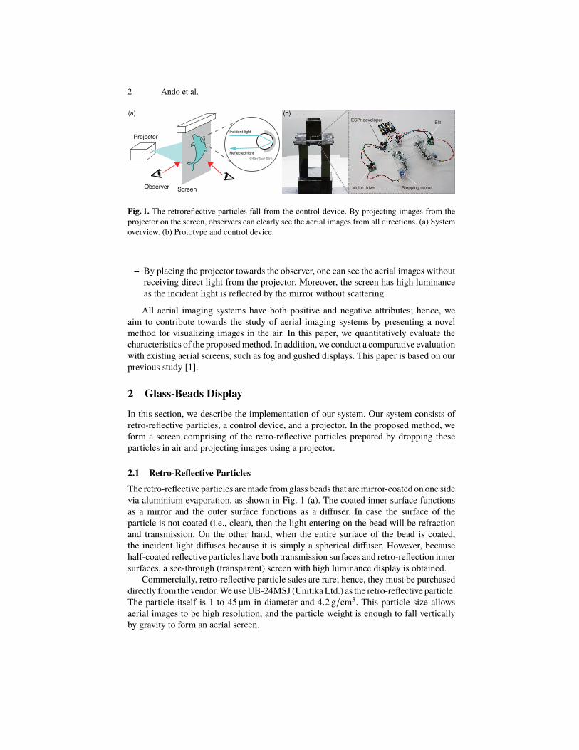
Fig. 1. The retroreflective particles fall from the control device. By projecting images from theprojector on the screen, observers can clearly see the aerial images from all directions. (a) Systemoverview. (b) Prototype and control device.
– By placing the projector towards the observer, one can see the aerial images withoutreceiving direct light from the projector. Moreover, the screen has high luminanceas the incident light is reflected by the mirror without scattering.
All aerial imaging systems have both positive and negative attributes; hence, weaim to contribute towards the study of aerial imaging systems by presenting a novelmethod for visualizing images in the air. In this paper, we quantitatively evaluate thecharacteristics of the proposed method. In addition, we conduct a comparative evaluationwith existing aerial screens, such as fog and gushed displays. This paper is based on ourprevious study [1].
2 Glass-Beads Display
In this section, we describe the implementation of our system. Our system consists ofretro-reflective particles, a control device, and a projector. In the proposed method, weform a screen comprising of the retro-reflective particles prepared by dropping theseparticles in air and projecting images using a projector.
2.1 Retro-Reflective ParticlesThe retro-reflective particles are made from glass beads that are mirror-coated on one sidevia aluminium evaporation, as shown in Fig. 1 (a). The coated inner surface functionsas a mirror and the outer surface functions as a diffuser. In case the surface of theparticle is not coated (i.e., clear), then the light entering on the bead will be refractionand transmission. On the other hand, when the entire surface of the bead is coated,the incident light diffuses because it is simply a spherical diffuser. However, becausehalf-coated reflective particles have both transmission surfaces and retro-reflection innersurfaces, a see-through (transparent) screen with high luminance display is obtained.
Commercially, retro-reflective particle sales are rare; hence, they must be purchaseddirectly from the vendor. We use UB-24MSJ (Unitika Ltd.) as the retro-reflective particle.The particle itself is 1 to 45 µm in diameter and 4.2 g/cm3. This particle size allowsaerial images to be high resolution, and the particle weight is enough to fall verticallyby gravity to form an aerial screen.
Glass-beads Display 3
Projector (for Glass-beads)
Observer
Aerial Screen (Glass-beads, Fog, Gas)
Projector (for Fog, Gas)
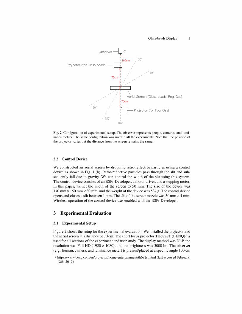
Fig. 2. Configuration of experimental setup. The observer represents people, cameras, and lumi-nance meters. The same configuration was used in all the experiments. Note that the position ofthe projector varies but the distance from the screen remains the same.
2.2 Control Device
We constructed an aerial screen by dropping retro-reflective particles using a controldevice as shown in Fig. 1 (b). Retro-reflective particles pass through the slit and sub-sequently fall due to gravity. We can control the width of the slit using this system.The control device consists of an ESPr-Developer, a motor driver, and a stepping motor.In this paper, we set the width of the screen to 50 mm. The size of the device was170 mm×150 mm×80 mm, and the weight of the device was 537 g. The control deviceopens and closes a slit between 1 mm. The slit of the screen nozzle was 50 mm × 1 mm.Wireless operation of the control device was enabled with the ESPr-Developer.
3 Experimental Evaluation
3.1 Experimental Setup
Figure 2 shows the setup for the experimental evaluation. We installed the projector andthe aerial screen at a distance of 70 cm. The short focus projector TH682ST (BENQ)3 isused for all sections of the experiment and user study. The display method was DLP, theresolution was Full HD (1920 × 1080), and the brightness was 3000 lm. The observer(e.g., human, camera, and luminance meter) is present/placed at a specific angle 100 cm
3 https://www.benq.com/en/projector/home-entertainment/th682st.html (last accessed February,12th, 2019)

4 Ando et al.
away from the screen. We used three types of display for the aerial screen: glass-bead,fog, and gushed. Note that the position of the observer, the position of the projector,and the respective properties all remain the same. However, for the glass-bead display,a projector is placed between the observer and the screen. For the fog and gas displays,a screen is installed between the observer and the projector.
Fog Display A fog display was constructed to conduct comparative experiments. Thehardware consists of an ultrasonic transducer, blower fan, blower PVC pipe, and 3Dprinted nozzle. The atomization capacity of the ultrasonic oscillator was 500 ml / h andthe slit of the nozzle was 50 mm × 8 mm.
Gushed Display We also prepared a gushed display for comparative experiments. Tobuild the gushed display, we referred to the study by Suzuki et al. [6]. A cooling sprayemployed for cooling the human body in sports was adopted as a gas.
3.2 Display Result
We captured photographs from each aerial screen (fog, gas, and glass-bead) at anglesfrom 0 to 50 degrees, as shown in Fig. 3. All ISO were 6400, the F value was 8, andthe shutter speed was 1 / 60. For all aerial screens, clear images were obtained from thefront. However, as the angle increased the Mie scattering caused blurring on both thefog and gas screens.
Then, we captured the glass-bead screen from angles of 0 to 180 degrees, as shownin Fig. 4. The proposed method obtained clear results irrespective of the viewing angle.
3.3 Luminance and Viewing Angle
We measured the luminance with respect to the viewing angle for each display. Theprocedure for measuring the luminance is as follows.
1. Construct an aerial screen of fog, gas, or glass beads.2. Place the luminance meter at a distance of 70 cm at an angle of N degrees.3. Project a white image from the projector.4. Considering the turbulence of the screen, five measurement values are recorded and
averaged.5. Change the angle N with increments of 10° in a range from 0° to 80°.
We employed LS-160 (KONICA MINOLTA, INC.)4 as a luminance meter. Allexperiments were conducted in a dark room.
4 https://sensing.konicaminolta.us/products/ls-160-luminance-meter/ (last accessed February,12th, 2019)

Glass-beads Display 5
Fog
Gas
Ours
Fog
Gas
Ours
0° 10° 20° 30° 40° 50°
Fig. 3. Comparison of images obtained from different angles on fog, gas, and glass bead screens.
Result The luminance values in the case of center (i.e., 0°) was 89.93 cd/m2 for fog,506.82 cd/m2 for gas, and 119.86 cd/m2 for ours. From the results, the gas screenpossesses the highest brightness value. Glass beads possessed higher brightness valuescompared to the fog screens.
Figure 5 shows the decrease in luminance versus angle. The horizontal axis representsthe angle and the vertical axis represents the normalized luminance. The luminance infog and gas screens sharply decrease at 20 degrees. The luminance becomes 10% orless when the fog is 20 degrees and the gas is 40 degrees. In addition, it was difficult tomeasure the luminance over 80 degrees. Contrarily, though the luminance of the glassbead screen decreased by 50% at 10 degrees, a detectable luminance value was obtainedeven at 80 degrees.
4 User Feedback
We conducted a user study with 15 participants (13 males and 2 females, with a meanage of 21 and a standard deviation (SD) of 3.43) for evaluating the performance of eachaerial screen.
4.1 Procedure
Three screens of fog, gas, and glass beads were arranged side by side, each with theconfigurations as follows Sec. 3. To prevent the participants from identifying the material

6 Ando et al.
input image 0° 30° 60° 120° 150° 180°
HELLO
Color Checker Pattern
Text
Fig. 4. Photograph of the projected image of colored checker pattern and text at each angle. Inputimage is shown in the leftmost column.
0 10 20 30 40 50 60 70 80 90 100 110 120 130 140 150 160 170 180angle
0.0
0.1
0.2
0.3
0.4
0.5
0.6
0.7
0.8
0.9
1.0
lum
inan
ce
foggasours
Fig. 5. Decrease of the luminance value with respect to the angle. The maximum value is 1 andthe ratio is as shown. Glass beads possess a wide viewing angle, whereas fog and gas possess alarge brightness value (depending on the viewing angle).
of the screen, each screen was called display 1 (fog), display 2 (gas), and display 3 (glassbeads) during the experiment. We projected three images of earth, text, and a coloredchecker pattern on each screen. Participants observed the images from the front of eachdisplay. Each image (earth, text, and checker pattern) was displayed for approximately 5seconds. Subsequently, the participants were asked to rate each screen on a scale of 1 to5, where 1 = poor, 2 = unsure, 3 = fair, 4 = good, and 5 = excellent. The screen featuresbeing rated were as follows:
– Luminance: bright or dark.– Contrast: high or low.– Sharpness: sharp or blurred.– Visibility: easy to see or hard.– Prefer: like or hate.
After observing displays 1 to 3, the participants could re-observe another displayand were able to update their ratings. After observing from the front, the experiment

Glass-beads Display 7
M SD
Fog 3.87 0.41
Gas 7% 3.87 0.27
Ours 7% 3.87 0.27
Fog 7% 3.60 0.40
Gas 3.73 0.21
Ours 7% 7% 3.80 0.31
Fog 7% 2.53 0.41
Gas 7% 3.67 0.38
Ours 4.00 0.00
Fog 7% 2.47 0.70
Gas 7% 3.53 0.41
Ours 3.87 0.12
Fog 3.00 0.86
Gas 3.73 0.21
Ours 4.00 0.00
27% 70%
100%
20%73%
33% 60%
100%
20%40% 40%
86%
53% 40%
20% 73%
100%
93%
27% 66%
13%
27% 73%
poor unsure fair good excellent
Luminance
Contrast
Sharpness
Visibility
Prefer
100%0%
27% 60%
93%
M SD
Fog 7% 3.20 1.17
Gas 7% 3.47 0.70
Ours 4.00 0.00
Fog 2.40 1.28
Gas 2.80 1.03
Ours 7% 3.87 0.27
Fog 7% 7% 7% 1.40 0.83
Gas 7% 1.33 0.38
Ours 4.00 0.00
Fog 7% 7% 1.20 0.31
Gas 7% 1.27 0.35
Ours 4.00 0.00
Fog 7% 1.93 1.07
Gas 1.93 0.78
Ours 4.00 0.00
13%
86%
80%
100%
47% 20% 27%
good excellent
13% 20% 60%
60%33%
100%
93%
13%
27% 27% 27% 20%
20% 40%
Visibility
Prefer
poor unsure fair
100%
27%33% 40%
100%0%
Luminance
Contrast
Sharpness
27%
20%63%
80%
100%
(a) (b)
Fig. 6. Results from user feedbacks. (a) Observed from the center. (b) Observed from an angle of30 degrees.
was conducted for observations from an oblique angle of 30 degrees using the sameprocedure.
4.2 Results
The results of the questionnaire are shown in Fig. 6. Our method recorded a higheraverage value than fog and gas screens despite the viewing angle (front or obliquely) forall the rated features.
When observed from the front, it was equivalent in luminance/contrast, but itssharpness/visibility was higher than both fog and gas. When observed from an angle,the contrast/sharpness/visibility of glass-beads screen was higher than both fog and gas.Moreover, its luminance did not change substantially, as compared to the other screens.Participants preferred our method in both the cases. Further, unlike fog and gas, ourapproach is robust against viewing angle.
5 Discussion and Future Work
5.1 Risk
We emphasize that the particles itself does not pollute the atmosphere and are safe totouch. However, because the size of the particles is exceedingly small, a risk similar tothat associated with volcanic ash exists. Accordingly, it is necessary to prevent themfrom entering the body and inhalation through the mouth and nose must be avoided.Wearing a dust prevention mask could be a solution, but wearing such masks createsnegative user experiences for the observers.
8 Ando et al.
5.2 Sustainability
It is impossible to reuse the retro-reflective particles in event of the inability to collectthem back. The projectable time of the aerial image depends on the number of beads.For instance, we dropped 1 kg of beads from the 50 mm × 1 mm slit and were able toproject the image on the aerial screen for 60 seconds. Because the projection time perparticle number is not very long, it is necessary to be able to reuse the glass beads forlonger projection times. Retro-reflective particles in itself can be reused multiple timesas they do not wear. For reusing these particles, methods such as sucking up the particleswith the help of a vacuum cleaner or lifting them (such as on a belt conveyor) can beused.
6 Conclusion
In this study, we presented a novel method to visualize aerial images using retro-reflectiveparticles and evaluated its display quality, luminance, and viewing angle. The resultsfrom the quantitative evaluation and the user feedback indicated that our proposedscreen has a wider viewing angle, better sharpness, and higher contrast compared to theconventional screens such as fog and gas. Our system enables the exploration of newapplication areas for the aerial imaging system and the expression of AR.
References
1. Ando, S., Otao, K., Takazawa, K., Tanemura, Y., Ochiai, Y.: Aerial imageon retroreflective particles. In: SIGGRAPH Asia 2017 Posters. pp. 7:1–7:2. SA’17, ACM, New York, NY, USA (2017). https://doi.org/10.1145/3145690.3145730,http://doi.acm.org/10.1145/3145690.3145730
2. Bingham, W.K.: Retroreflective sheet with enhanced brightness (Aug 16 1988), uS Patent4,763,985
3. Bischoff, A., Bullock, D.: Sign retroreflectivity study. Joint Transportation Research Programp. 190 (2002)
4. Lee, C., DiVerdi, S., Hollerer, T.: Depth-fused 3d imagery on an immaterial display. IEEEtransactions on visualization and computer graphics 15(1), 20–33 (2009)
5. Rakkolainen, I., DiVerdi, S., Olwal, A., Candussi, N., Hüllerer, T., Laitinen, M.,Piirto, M., Palovuori, K.: The interactive fogscreen. In: ACM SIGGRAPH 2005Emerging Technologies. SIGGRAPH ’05, ACM, New York, NY, USA (2005).https://doi.org/10.1145/1187297.1187306, http://doi.acm.org/10.1145/1187297.1187306
6. Suzuki, I., Yoshimitsu, S., Kawahara, K., Ito, N., Shinoda, A., Ishii, A., Yoshida, T.,Ochiai, Y.: Design method for gushed light field: Aerosol-based aerial and instant dis-play. In: Proceedings of the 8th Augmented Human International Conference. pp. 1:1–1:10. AH ’17, ACM, New York, NY, USA (2017). https://doi.org/10.1145/3041164.3041170,http://doi.acm.org/10.1145/3041164.3041170
7. Tokuda, Y., Norasikin, M.A., Subramanian, S., Martinez Plasencia, D.: Mistform: Adaptiveshape changing fog screens. In: Proceedings of the 2017 CHI Conference on Human Fac-tors in Computing Systems. pp. 4383–4395. CHI ’17, ACM, New York, NY, USA (2017).https://doi.org/10.1145/3025453.3025608, http://doi.acm.org/10.1145/3025453.3025608
8. Yukawa, S., Iwamoto, Y.: Retroreflective sheet (Mar 15 2011), uS Patent 7,906,193