GL840-M and GL840-WV Data Loggers · 2015-12-28 · GL840 Description 330-668-14442 Model GL840...
19
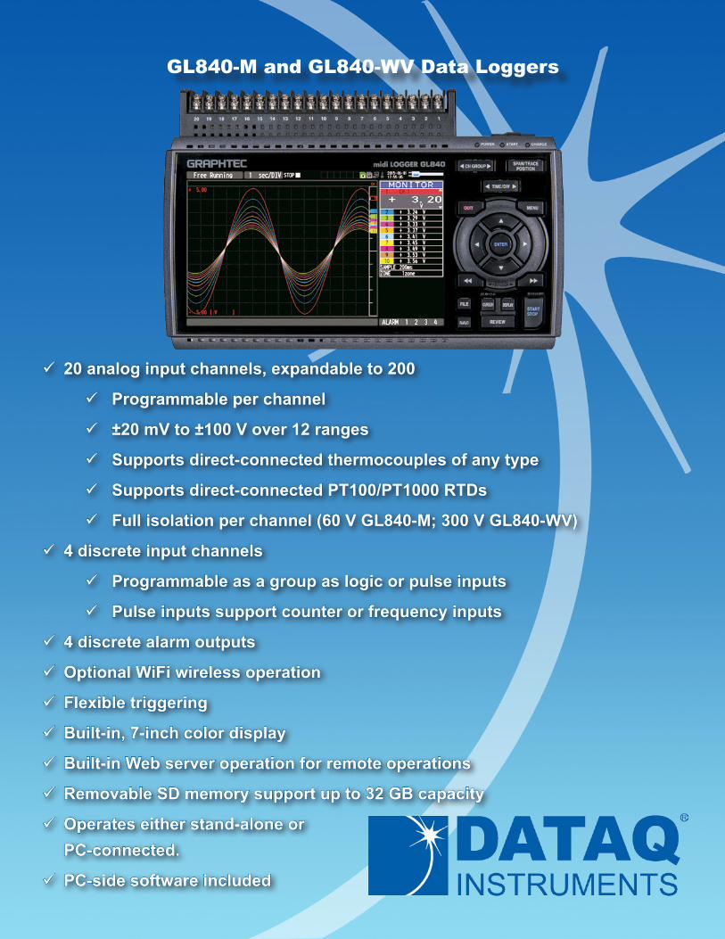
9 20 analog input channels, expandable to 200 9 Programmable per channel 9 ±20 mV to ±100 V over 12 ranges 9 Supports direct-connected thermocouples of any type 9 Supports direct-connected PT100/PT1000 RTDs 9 Full isolation per channel (60 V GL840-M; 300 V GL840-WV) 9 4 discrete input channels 9 Programmable as a group as logic or pulse inputs 9 Pulse inputs support counter or frequency inputs 9 4 discrete alarm outputs 9 Optional WiFi wireless operation 9 Flexible triggering 9 Built-in, 7-inch color display 9 Built-in Web server operation for remote operations 9 Removable SD memory support up to 32 GB capacity 9 Operates e ither stand-alone or PC-connect ed. 9 PC-side software included GL840-M and GL840-WV Data Loggers
Transcript of GL840-M and GL840-WV Data Loggers · 2015-12-28 · GL840 Description 330-668-14442 Model GL840...
9 20 analog input channels, expandable to 200
9 Programmable per channel
9 ±20 mV to ±100 V over 12 ranges
9 Supports direct-connected thermocouples of any type
9 Supports direct-connected PT100/PT1000 RTDs
9 Full isolation per channel (60 V GL840-M; 300 V GL840-WV)
9 4 discrete input channels
9 Programmable as a group as logic or pulse inputs
9 Pulse inputs support counter or frequency inputs
9 4 discrete alarm outputs
9 Optional WiFi wireless operation
9 Flexible triggering
9 Built-in, 7-inch color display
9 Built-in Web server operation for remote operations
9 Removable SD memory support up to 32 GB capacity
9 Operates either stand-alone orPC-connected.
9 PC-side software included
GL840-M and GL840-WV Data Loggers

GL840 Description
330-668-1444 2 www.dataq.com
Model GL840 Series is a third-generation data logger product with exceptional price/performance. It’s a 20 analog chan-nel device expandable to 200 channels, augmented by four discrete inputs and outputs. Its discrete inputs can be con-figured as a group to be either logic inputs or pulse inputs. When configured for pulse, each of the four channels can be configured to measure frequency or to count. The four discrete outputs are alarms that can be triggered by a variety of eas-ily-defined analog and pulse/discrete input channel conditions. The 20 GL840 analog input channels may each be config-ured to measure a direct connected voltage in the range of 20 mV to 100 V full scale across 12 ranges, a direct-connected thermocouple of any type, or a 3-wire PT100 or PT1000 RTD. Each of the GL840’s analog input channels is electrically isolated from other channels and from power ground allowing off-ground measurements using shunts, as well as powered or grounded thermocouples. Further, two GL840 versions are available to tolerate up to a 60 or 300 Vp-p common mode voltage. Model GL840-M supports up to 60 Vp-p common mode. Model GL840-WV supports up to 300 Vp-p common mode to address more aggressive applications, like stacked battery cell measurements for both temperature and voltage.The most powerful GL840 feature is its triggering flexibility. Data recording can be independently started or stopped as a function of analog and pulse/discrete signal level (single or windowed), alarm, date and time, and day-of-the-week. Trig-gers can also be configured to operate only once, or to automatically repeat. The ability of the GL840 to adapt to virtually any desired trigger condition allows the instrument to operate unattended for long periods of time with complete autono-my.The GL840 operates either connected to a PC or entirely stand-alone. Connection to a PC may be over a standard Ether-net, USB, or optional wireless connection. Each connection approach may take advantage of supplied PC-side software to configure, acquire, display, and record digitized information for storage directly to the PC’s HDD. Acquired data may be retrieved for review and analysis after recording, including the ability to export to Microsoft Excel. Using the GL840’s built-in Ethernet port or wireless option enables the instrument’s networking features, allowing it to be remotely config-ured and managed using the standard Web browser of any computer or smart phone. Automatic backup of data acquired to a user-accessible SD memory card is also supported via its FTP facility. Finally, the measurement reach of the GL840 is further extended by use of GS Sensor accessories that can be either con-nected directly to the GL840 or wirelessly accessed with the B-568 wireless option using the GL100-WL. Extended mea-surements of temperature/humidity, acceleration, CO2, illuminance, ac current, and more are available using GS Sensors.
GL840 Close Up
www.dataq.com 3 330-668-1444
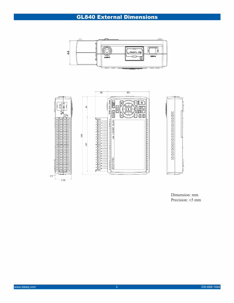
GL840 External Dimensions
Dimension: mmPrecision: ±5 mm
330-668-1444 4 www.dataq.com
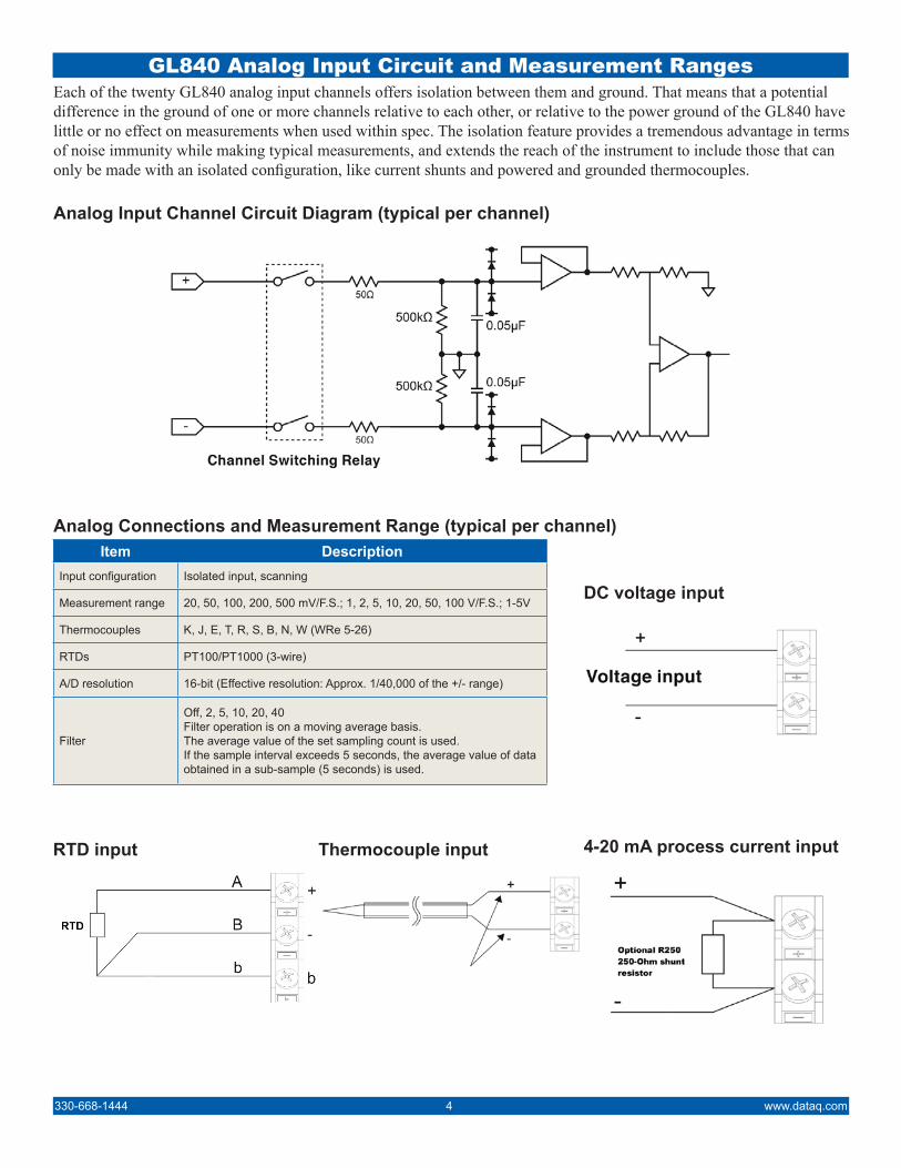
GL840 Analog Input Circuit and Measurement RangesEach of the twenty GL840 analog input channels offers isolation between them and ground. That means that a potential difference in the ground of one or more channels relative to each other, or relative to the power ground of the GL840 have little or no effect on measurements when used within spec. The isolation feature provides a tremendous advantage in terms of noise immunity while making typical measurements, and extends the reach of the instrument to include those that can only be made with an isolated configuration, like current shunts and powered and grounded thermocouples.
Analog Input Channel Circuit Diagram (typical per channel)
Item DescriptionInput configuration Isolated input, scanning
Measurement range 20, 50, 100, 200, 500 mV/F.S.; 1, 2, 5, 10, 20, 50, 100 V/F.S.; 1-5V
Thermocouples K, J, E, T, R, S, B, N, W (WRe 5-26)
RTDs PT100/PT1000 (3-wire)
A/D resolution 16-bit (Effective resolution: Approx. 1/40,000 of the +/- range)
Filter
Off, 2, 5, 10, 20, 40 Filter operation is on a moving average basis. The average value of the set sampling count is used. If the sample interval exceeds 5 seconds, the average value of data obtained in a sub-sample (5 seconds) is used.
DC voltage input
Thermocouple input 4-20 mA process current input
Analog Connections and Measurement Range (typical per channel)
RTD input
www.dataq.com 5 330-668-1444
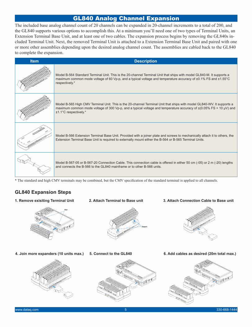
GL840 Analog Channel ExpansionThe included base analog channel count of 20 channels can be expanded in 20-channel increments to a total of 200, and the GL840 supports various options to accomplish this. At a minimum you’ll need one of two types of Terminal Units, an Extension Terminal Base Unit, and at least one of two cables. The expansion process begins by removing the GL840s in-cluded Terminal Unit. Next, the removed Terminal Unit is attached to a Extension Terminal Base Unit and paired with one or more other assemblies depending upon the desired analog channel count. The assemblies are cabled back to the GL840 to complete the expansion.
Item Description
Model B-564 Standard Terminal Unit. This is the 20-channel Terminal Unit that ships with model GL840-M. It supports a maximum common mode voltage of 60 Vp-p, and a typical voltage and temperature accuracy of ±0.1% FS and ±1.55°C respectively.*
Model B-565 High CMV Terminal Unit. This is the 20-channel Terminal Unit that ships with model GL840-WV. It supports a maximum common mode voltage of 300 Vp-p, and a typical voltage and temperature accuracy of ±(0.05% FS + 10 µV) and ±1.1°C respectively.*
Model B-566 Extension Terminal Base Unit. Provided with a joiner plate and screws to mechanically attach it to others, the Extension Terminal Base Unit is required to externally mount either the B-564 or B-565 Terminal Units.
Model B-567-05 or B-567-20 Connection Cable. This connection cable is offered in either 50 cm (-05) or 2 m (-20) lengths and connects the B-566 to the GL840 mainframe or to other B-566 units.
* The standard and high CMV terminals may be combined, but the CMV specification of the standard terminal is applied to all channels.
GL840 Expansion Steps1. Remove exisiting Terminal Unit 2. Attach Terminal to Base unit 3. Attach Connection Cable to Base unit
4. Join more expanders (10 units max.) 5. Connect to the GL840 6. Add cables as desired (20m total max.)

330-668-1444 6 www.dataq.com
GL840 Discrete I/O and Pulse InputsDepending upon the application, discrete I/O and pulse inputs can play a crucial data logging role. The GL840 supports four discrete alarm outputs that can signal alarm or event states that are a function of virtually any combinations of analog and pulse or discrete input values. These alarm outputs may be used to handshake with a PLC or other devices to start or stop processes or simply signal the beginning or end of events. The GL840 also offers four discrete input ports, which may be configured as simple binary true/false input flags, or for pulse and counter inputs. Pulse inputs can be used to acquire frequency data such as rpm or flow, or reconfigured to acquire count data to derive volume from flow or simply count the number of iterations from a process. Pulse data is neatly folded into acquired analog data so that all measured parameters can be evaluated in the same timeframe during analysis to easily identify cause and effect. A final discrete input is re-served for externally triggering the GL840’s A-D conversion to allow the instrument to synchronize to external processes. Access to all discrete I/O requires the B-513 cable option.
Item DescriptionNumber of input channels 4 (switch between logic and pulse)
Input voltage range 0 to +24V max. (single-ended ground input)
Threshold level Approx. +2.5V
Hysteresis Approx. 0.5 V (+2.5 to +3 V)
Logic/Pulse Input Specifications
Item DescriptionNumber of input channels 1
Input voltage range 0 to +24V max. (single-ended ground input)
Threshold level Approx. +2.5V
Hysteresis Approx. 0.5 V (+2.5 to +3 V)
Trigger Input/External Sampling Input Specifications
Item DescriptionNumber of output channels 4
Output format Open collector output +5 V, 10 KΩ pull-up resistance
Alarm Output Specifications
Discrete I/O Instrument-side Equivalent Circuits
www.dataq.com 7 330-668-1444
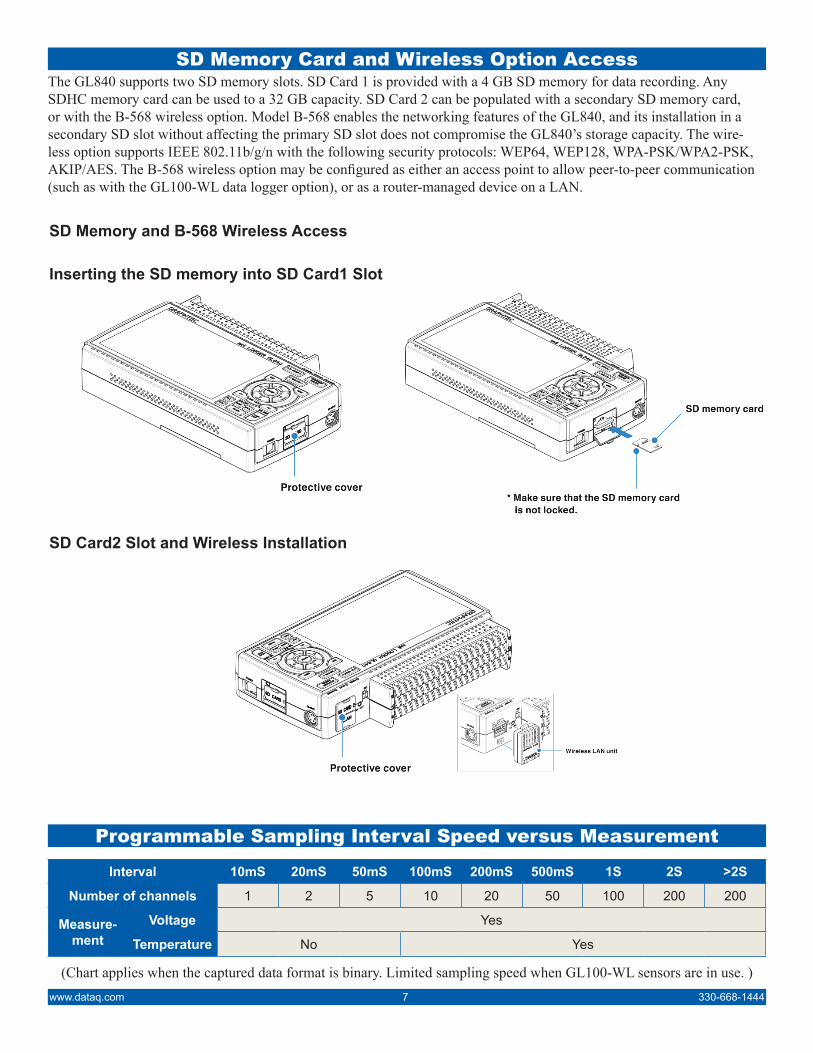
SD Memory Card and Wireless Option Access
Programmable Sampling Interval Speed versus Measurement
The GL840 supports two SD memory slots. SD Card 1 is provided with a 4 GB SD memory for data recording. Any SDHC memory card can be used to a 32 GB capacity. SD Card 2 can be populated with a secondary SD memory card, or with the B-568 wireless option. Model B-568 enables the networking features of the GL840, and its installation in a secondary SD slot without affecting the primary SD slot does not compromise the GL840’s storage capacity. The wire-less option supports IEEE 802.11b/g/n with the following security protocols: WEP64, WEP128, WPA-PSK/WPA2-PSK, AKIP/AES. The B-568 wireless option may be configured as either an access point to allow peer-to-peer communication (such as with the GL100-WL data logger option), or as a router-managed device on a LAN.
SD Memory and B-568 Wireless Access
Inserting the SD memory into SD Card1 Slot
SD Card2 Slot and Wireless Installation
Interval 10mS 20mS 50mS 100mS 200mS 500mS 1S 2S >2S
Number of channels 1 2 5 10 20 50 100 200 200
Measure-ment
Voltage Yes
Temperature No Yes
(Chart applies when the captured data format is binary. Limited sampling speed when GL100-WL sensors are in use. )

330-668-1444 8 www.dataq.com
B-568 Wireless Option Networking ModesUse the B-568’s access point mode to network the GL840 with the optional GL100-WL (up to 5 units) to expand measure-ment flexibility, or to provide direct peer-to-peer access to a PC and even a smart phone. Alternatively, the B-568’s router mode neatly folds the GL840 into an existing LAN. The B-568 wireless option or hard-wired Ethernet enables an entire upper level of GL840 performance in terms of FTP backup, Web server operation, and email notification. Web server mode supports all popular Web browsers and allows remote operation of the GL840 and real time screen monitoring.
As a Wireless Access Point
As a Router-managed Device
E-mail ConfigurationsSelection item Description
E-mail address
TO: Set the e-mail address of the e-mail destination. (Up to 63 characters)
CC1: to CC3: Up to three e-mail addresses can be set as CC (carbon copy). (Up to 63 characters)
Subject: The e-mail subject. (Up to 63 characters)
Notification
Alarm When it is set to On, the occurrence of alarm is notified.
Low battery When it is set to On, the low battery information is notified.
Low communication strength When it is set to On, the low communication strength information is notified.
SD memory card free space When it is set to On, the SD memory card free space information is notified.
Periodic notification Set the time to send the notification setting information with the e-mail to any address.

www.dataq.com 9 330-668-1444
Connecting the GL840 Directly To A PCDon’t need a wireless or hard-wired LAN? No problem. The GL840’s integral USB port allows it to connect directly to a PC on to which is typically installed the included Graphtec APS software for real time data acquisition.
Internal Battery Pack Option B-569The GL840 supports one or two battery packs, option (B-569), that allows operation independent of ac power. A fully charged battery allows an operating time of 5 hours (one battery pack) to 10 hours (two battery packs) depending upon data logging configuration. The battery can also operate as a UPS (uninterruptable power supply.) In the event that ac power is lost, the GL840 will seamlessly continue operation on battery power without data logging disruption.
Use a crossover cable when connecting the GL840 directly to a PC. Otherwise, a standard Ethernet cable can be used. Ethernet Connection
330-668-1444 10 www.dataq.com
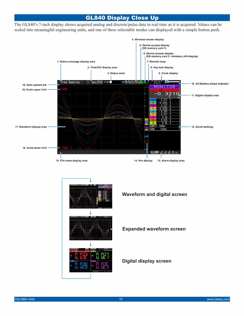
GL840 Display Close UpThe GL840’s 7-inch display shows acquired analog and discrete/pulse data in real time as it is acquired. Values can be scaled into meaningful engineering units, and one of three selectable modes can displayed with a simple button push.
Waveform and digital screen
Expanded waveform screen
Digital display screen

GL840 Analog Measurement Modes
Function Channels Measurements Comments
Analog 20 (expandable to 200)
Voltage ±20 mV to ±100 V
Thermocouple Types K, J, E, T, R, S, B, N, W (WRe 5-26)
4-20 mA Requires R250, 250-Ohm current shunt
Humidity Requires B-530 humidity sensor option
RTD 3-wire PT100, PT1000
Discrete 4Logic True/false
Pulse Count, instantaneous count, revolution
www.dataq.com 11 330-668-1444
The GL840 in tandem with the optional GL100-WL wireless add-on or its GS Sensor accessories is capable of a remark-able range of measurements. Measurements that the GL840 can make on its own are voltage, 4-20 mA process current (with optional R250 shunt resistor), thermocouple, RTD, and humidity (with optional B-530 sensor.) When a GL100-WL is added to the mix (requires the optional B-568 wireless interface), the GL840 has wireless access to an additional range of measurements. Without the wireless option or the GL100-WL, the GL840 directly accepts GS Series add-on modules. Direct GL840 Measurements
Model Channels Measurements Alarms CommentsGL100-WL - - 1* Provides wireless access to the GL240
GS-TH 4 Ambient temperature and RH -
GS-3AT 4 Temp + 3-axis acceleration -
GS-4VT 4 Thermocouple/voltage - Programmable per channel. Supports K and J TCs
GS-4TSR 4 Thermistor -
GS-LXUV 4 Illuminance / Ultraviolet -
GS-CO2 1 CO2 -
GS-DPA-AC 4 AC current sensor (1 or 3 phase) -
GS-DPA
- Dual branch adator -
Used to combine (pair) the indicated modules8 GS-TH + GS-LXUV -
5 GS-TH + GS-CO2 -
5 GS-CO2 + GS-LXUV -
GL100-WL Add-on Modules (refer to the GL100 Accessories datasheet for details)
* GS modules support a level alarm function that is detected by the GL100-WL and communicated to a wireless-equipped GL840.
Use GS Series Add-ons Wirelessly with a GL100-WL, or Directly Connected

330-668-1444 12 www.dataq.com
GL840 Global Device Measurement SettingsThe GL840 allows an array of settings that define how all of its channel information is acquired. The following table pro-vides a overview of the major setting categories and selections within them:
Measurements CommentsSampling 10, 20, 50, 100, 125, 200, 250, 500ms, 1, 2, 5, 10, 20, 30s, 1, 2, 5, 10, 20, 30min, 1h; External
Capture destination SD CARD 1, SD CARD 2
File Name Name of the recorded data file
Ring/Relay capture Off, Ring, Relay
Ring capture Number of recording points
AC Line Filter Off, On
Backup
Backup Interval Off, 1, 2, 6, 12, 24 hours
Backup Destination SD CARD 1 (SD1), SD CARD 2 (SD2), FTP
Save Folder Folder name
Calc. Settings 1 Off, Average, Max, Min, Peak, RMS
Calc. Settings 2 Off, Average, Max, Min, Peak, RMS
“Ring Capture” and “Relay Capture” ExplainedIn addition to continuous data logging, the GL840 supports two special-purpose recording modes: Ring and Relay Cap-ture.The Ring Capture feature allows the GL840 to acquire a definable number of data values to consecutive data files while automatically deleting the oldest file. For example, if 1,000 data points are specified, data is acquired to File 1 until 1,000 data values have been recorded. Recording then seamlessly continues to File 2 for another 1,000 values. Before data recording continues to File 3 for another 1,000 data values, File 1 is deleted. When File 3 is full, File 2 is deleted and re-cording continues to File 4. This process continues until recording stops. In this manner Ring Capture allows data logging to continue indefinitely without concern for filling the target memory. Further, since the number of data values recorded to each file and sampling interval are definable and constant, the timeframe before data is erased is precisely known in advance. Thus, all critical data leading up to, during, and after an event can be captured for analysis. Maximum file size is 2 GB, but SD memory sizes as large as 32 GB are supported. The Relay Capture feature of the GL840 is almost identical to Ring Capture, except that data files are never deleted. The feature essentially exchanges unlimited record time for an entire history of recorded data. Like Ring Capture, maximum file size is 2 GB, but SD memory sizes as large as 32 GB are supported.
“External Sampling” ExplainedSometimes asynchronous sampling rates just won’t do. If you need to acquire data at a precise moment that’s coincident with an event, and you can generate a trigger signal for that occurrence, External sampling can be used. The following dia-gram describes the timing relationship between the various components that define an externally triggered application.

Start or Stop Recording on Any Trigger ConditionThe GL840’s range of stop and start trigger conditions is massive and unrivaled. Select from single or windowed levels to the day and time of the week with everything in between per pulse or analog channel. Want to start or stop acquiring data when the signal level on channel 1 is above 200 psi, but only on Saturday at 12 noon? No problem. Finally, select Boolean AND/OR operators to tie any variety of trigger conditions together. Finally, trigger conditions can be independently set for the GL840’s alarm output ports as a function of virtually any com-bination of analog or pulse input values. The following table describes the array of GL840 trigger conditions to stop, start, or alarm the instrument:
Setting Selections availableStart Side Source Setting Off, Level, Alarm, External Input, Date, Weekly, Time
[Level]
ModeAnalog: Off, H, L, Window In, Window Out Logic: Off, H, L Pulse: Off, H, L, Window In, Window Out
Combination Level OR, Level AND, Edge OR, Edge AND
Level Set numeric value
[Alarm] Alarm port number 1, 2, 3, 4, WL1
[Date]Date From 2005.1.1 to 2035.12.31
Time From 0:0:0 to 23:59:59
[Weekly]Day of week Off or On setting for each of Sunday through Saturday
Time From 0:0:0 to 23:59:59
[Time] From 0:0:1 to 9999:59:59
Stop Side Source Setting Off, Level, Alarm, External Input, Date, Weekly, Time
[Level]
ModeAnalog: Off, H, L, Window In, Window Out Logic: Off, H, L Pulse: Off, H, L, Window In, Window Out
Combination Level OR, Level AND, Edge OR, Edge AND
Level Set numeric value
[Alarm] Alarm port number 1, 2, 3, 4, WL1
[Date]Date From 2005.1.1 to 2035.12.31
Time From 0:0:0 to 23:59:59
[Weekly]Day of week Off or On setting for each of Sunday through Saturday
Time From 0:0:0 to 23:59:59
[Time] From 0:0:1 to 9999:59:59
Repeated Capturing Off, On
Alarm Level Settings
ModeAnalog: Off, H, L, Window In, Window Out Logic: Off, H, L Pulse: Off, H, L, Window In, Window Out
Level Set numeric value
Output 1, 2, 3, 4, WL1
Detection Method Level, Edge
Alarm Hold Held or Not held
Send Burnout Alarm Sent or not sent
www.dataq.com 13 330-668-1444

330-668-1444 14 www.dataq.com
Trigger Operations Close UpTrigger and Alarm Operations
Rising Falling
Window-in Window-out
General Record TimeThe following record time table assumes analog channels only with Logic/Pulse inputs disabled. Figures are approximate. File size of captured data is 2GB in GBD or CSV file format. Sampling interval is limited by the number of channels in use.
Sampling Interval (10 acquired channels)
Storage Format 10mS 50mS 100mS 200mS 500mS 1S 10S
Binary 31 days 77 days 95 days 108 days 270 days >365 days >365 days
CSV 3 days 11 days 16 days 21 days 54 days 109 days >365 days
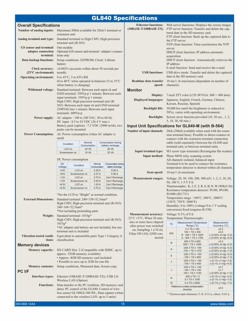
Ethernet functions:(10BASE-T/100BASE-TX)
Web server functions: Displays the screen imagesFTP server function: Transfer and delete the cap-tured data in the SD memory card.FTP client function: Back up the captured data to the FTP server.NTP client function: Time-synchronize the NTP server.DHCP client function: IP address automatic acquisitionDHCP client function : Automatically retrieves the IP addressE-mail function: Send and receive the e-mail
USB functions: USB drive mode: Transfer and delete the captured data in the SD memory card.
Realtime data transfer speed:
10 ms/1 ch maximum (dependant on number of channels).
MonitorDisplay: 7-inch TFT color LCD (WVGA: 800 × 480 dots)
Displayed languages: Japanese, English, French, German, Chinese, Korean, Russian, Spanish
Backlight life: 50,000 hrs (until the brightness is reduced to 50%), varies with operating environment.
Backlight: Screen saver function provided (10, 30 sec., 1, 2, 5, 10, 30, 60 min.)
Input Unit Specifications for GL840-M (with B-564)Number of input channels: 20ch (200ch available when used with the exten-
sion terminal base). Possible to direct-connect or connect with the extension terminal connection cable (sold separately) between the GL840 and terminal unit, or between terminal units.
Input terminal type: M3 screw type terminals (Rectangular flat washer)Input method: Photo MOS relay scanning system
All channels isolated, balanced inputTerminal b to be used to connect the resistance temperature detector is shorted within all channels.
Scan speed: 10 ms/1 ch maximum
Measurement ranges: Voltage: 20, 50, 100, 200, 500 mV; 1, 2, 5, 10, 20, 50, 100 V; 1-5 V F.S.Thermocouples : K, J, E, T, R, S, B, N, W (WRe5-26)Resistance temperature detector: Pt100, JPt100, Pt1000 (IEC751)Temperature range : 100°C, 500°C, 2000°C (150°F, 750°F, 3000°F)Humidity: 0 to 100% (voltage 0 to 1 V scaling conversion) fixed (requires B-530)
Measurement accuracy:23°C ±5°C; When 30 min-utes or more have elapsed after power was switched
on; Sampling 1 s/10 ch; Filter ON (10); GND con-
nected
Voltage: 0.1% of F.S.Temperature Thermocouple:
TC Measurement Temperature Range (°C)
MeasurementAccuracy (°C)
R/S
0 ≤ TS ≤ 100100 < TS ≤ 300
R : 300 < TS ≤ 1600S : 300 < TS ≤ 1760
±5.2±3.0
± (0.05% of rdg +2.0)± (0.05% of rdg +2.0)
B 400 ≤ TS ≤ 600600 < TS ≤ 1820
±3.5± (0.05% of rdg +2.0)
K -200 ≤ TS ≤ -100-100 < TS ≤ 1370
± (0.05% of rdg +2.0)± (0.05% of rdg +1.0)
E -200 ≤ TS ≤ -100-100 < TS ≤ 800
± (0.05% of rdg +2.0)± (0.05% of rdg +1.0)
T -200 ≤ TS ≤ -100-100 < TS ≤ 400
± (0.1% o f rdg +1.5)± (0.1% o f rdg +0.5)
J-200 ≤ TS ≤ -100-100 < TS ≤ 100100 < TS ≤ 1100
±2.7±1.7
± (0.05% of rdg +1.0)
N -200 ≤ TS < 00 ≤ TS ≤ 1300
± (0.1% o f rdg +2.0)± (0.1% o f rdg +1.0)
W 0 ≤ TS ≤ 2000 ± (0.1% o f rdg +1.5)Reference contact compensation
accuracy ±0.5
* Thermocouple diameters T, K: 0.32 φ, others: 0.65 φ
Overall SpecificationsNumber of analog inputs: Maximum 200ch available for 20ch/1 terminal or
extension unitAnalog terminal unit type: Standard terminal or High CMV, High-precision
terminal unit (B-565)GS sensor and terminal/
adapter connection terminal:
One moduleOptional (GS sensor and terminal / adapter ) connec-tions only
Data backup functions: Setup conditions: EEPROM; Clock: Lithium battery
Clock accuracy:(23°C environment)
±0.002% (accurate within about 50 seconds per month)
Operating environment: 0 to 45°C, 5 to 85% RH(0 to 40°C when operated in batteries/15 to 35°C when battery is charging)
Withstand voltage: Standard terminal: Between each input ch and GND terminal: 350Vp-p 1 minute; Between each input terminals: 350Vp-p 1 minuteHigh CMV, High-precision terminal unit (B-565): Between each input ch and GND terminal: 2300VACrms 1 minute; Between each input terminals: 600Vp-p
Power supply: AC adapter : 100 to 240 VAC, 50 to 60 HzDC input : 8.5 to 24 VDC (26.4 V max.)Battery pack (option) : 7.2 VDC (2900 mAh), two packs can be mounted
Power Consumption: AC Power consumption (when AC adapter is used)
Condition NormalConsumption
Consumption during battery recharge
LCD on 24 VA 38 VAScreensaver on 19 VA 33 VA
DC Power consumptionDC
Voltage Condition NormalConsumption
Consumption duringbattery recharge
+24V LCD on 0.36 A 0.65 A+24V Screensaver on 0.27 A 0.56 A+12V LCD on 0.70 A Can’t Recharge+12V Screensaver on 0.50 A Can’t Recharge+8.5V LCD on 1.00 A Can’t Recharge+8.5V Screensaver on 0.70 A Can’t Recharge
*Set the LCD to “Bright” as normal condition.External Dimensions: Standard terminal: 240×158×52.5mm*
High CMV, High-precision terminal unit (B-565): 240×166×52.5mm**Not including protruding parts
Weight: Standard terminal: 1010g*High CMV, High-precision terminal unit (B-565): 1035g**AC adapter and battery are not included, but one terminal unit is included
Vibration-tested condi-tions:
Equivalent to automobile parts Type 1 Category A classification
Memory devicesMemory capacity: SD CARD Slot: 2 (Compatible with SDHC, up to
approx. 32GB memory available)• Approx. 4GB SD memory card included• Possible to save up to 2GB for one file
Memory contents: Setup conditions, Measured data, Screen copy
PC I/FInterface types: Ethernet (10BASE-T/100BASE-TX); USB 2.0;
Wireless LAN (Option)Functions: Data transfer to the PC (realtime, SD memory card
data); PC control of the GL840; Control of wire-less sensor GL100GL100-WL, Data capture (when connected to the wireless LAN: up to 5 units)
GL840 Specifications
330-668-1444 15 www.dataq.com

Measurement Accuracy (cont.):
Resistance temperature detector:
Type Measurement Tempera-ture Range (°C)
AppliedCurrent
MeasurementAccuracy (°C)
Pt100 -200 to 850 (FS=1050) 1mA ±1.0JPt100 -200 to 500 (FS=700) 1mA ±0.8Pt1000 -200 to 500 (FS=700) 0.3mA ±0.8
*3-wire systemTemperature Range:
Type Temperature Range (°C F.S.) Resolution Measurement
Range (°C)
R/S
100 0.01 0 to 100500 0.05 0 to 500
2000 0.1 R: 0 to 1600S: 0 to 1760
B500 0.05 400 to 500
2000 0.1 500 to 1820
K/E/T/J/N
100 0.01 -100 to 100
500 0.05 K/E/J/N: -200 to 500T : -200 to 400
2000 0.1
K : -200 to 1370E : -200 to 800T : -200 to 400J : -200 to 1100N : -200 to 2000
W100 0.01 0 to 100500 0.05 0 to 500
2000 0.1 0 to 2000
Pt
100 0.01 -100 to 100500 0.05 -200 to 500
2000 0.1Pt100: -200 to 850
JPt100/Pt1000: -200 to 500
*Measurement accuracy does not change due to the temperature range
Reference contact com-pensation accuracy:
Internal/External switching
A/D converter: Method:ΔΣ method; Resolution:16-bit (Effective resolution: About 1/40,000 of the +/- range)
Temperature coefficient: Gain : 0.01% of F.S./°C; Zero : 0.02% of F.S./°C(Occurs when sampling speed is 10, 20, or 50 ms.)
Input resistance: 1 MΩ ±5%Allowable signal source
resistance:Within 300Ω
Maximum permissible input voltage:
Between +/– input terminals :20mV to 2V range (60Vp-p); 5V to 100V range (110Vp-p)Between input terminal/input terminal :60 Vp-pBetween input terminal/GND :60 Vp-p
Withstand voltage: Between input terminal/input terminal : 350 Vp-p 1 minuteBetween input terminal/GND : 350 Vp-p 1 minute
Insulation resistance: Between input terminal/GND : 50MΩ or more (at 500 VDC)
Common mode rejection ratio:
90 dB or more (50/60 Hz; signal source 300Ω or less)
Noise: 48 dB or more (with +/– terminals shorted)Filter: Off, 2, 5, 10, 20, 40
Filter operation is on a moving average basis.The average value of the number of set samples is used. If the sample interval exceeds 30 seconds, the average value of data obtained in a sub-sample (30 seconds) is used.
Input Unit Specifications for GL840-WV (with B-565)Number of input channels: 20ch (200ch available when used with the exten-
sion terminal base). Possible to direct-connect or connect with the extension terminal connection cable (sold separately) between the GL840 and terminal unit, or between terminal units.
Input terminal type: M3 screw type terminals (Rectangular flat washer)Input method: Photo MOS relay scanning system
All channels isolated, balanced inputTerminal b to be used to connect the resistance temperature detector is shorted within all channels.
Scan speed: 10 ms/1 ch maximumMeasurement ranges: Voltage: 20, 50, 100, 200, 500 mV; 1, 2, 5, 10, 20,
50, 100 V; 1-5 V F.S.Thermocouples : K, J, E, T, R, S, B, N, W (WRe5-26)Resistance temperature detector: Pt100, JPt100, Pt1000 (IEC751)Temperature range : 100°C, 500°C, 2000°C (150°F, 750°F, 3000°F)Humidity: 0 to 100% (voltage 0 to 1 V scaling conversion) fixed (requires B-530)
Measurement accuracy:23°C ±5°C; When 30 min-utes or more have elapsed after power was switched
on; Sampling 1 s/10 ch; Filter ON (10); GND con-
nected
Voltage: ± (0.05% of F.S. + 10μV)Temperature Thermocouple:
TC Measurement Temperature Range (°C)
MeasurementAccuracy (°C)
R/S
0 ≤ TS ≤ 100100 < TS ≤ 300
R : 300 < TS ≤ 1600S : 300 < TS ≤ 1760
±4.5±3.0±2.2±2.2
B 400 ≤ TS ≤ 600600 < TS ≤ 1820
±3.5±2.5
K -200 ≤ TS ≤ -100-100 < TS ≤ 1370
±1.5±0.8
E -200 ≤ TS ≤ -100-100 < TS ≤ 800
±1.0±0.8
T -200 ≤ TS ≤ -100-100 < TS ≤ 400
±1.5±0.6
J-200 ≤ TS ≤ -100-100 < TS ≤ 100100 < TS ≤ 1100
±1.0±0.8±0.6
N -200 ≤ TS < 00 ≤ TS ≤ 1300
±2.2±1.0
W 0 ≤ TS ≤ 2000 ±1.8Reference contact compensation
accuracy ±0.3
* Thermocouple diameters T, K: 0.32 φ, others: 0.65 φ
Resistance temperature detector:
Type Measurement Tempera-ture Range (°C)
AppliedCurrent
MeasurementAccuracy (°C)
Pt100-200 ≤ TS ≤ 100100 < TS ≤ 500500 < TS ≤ 850
1mA±0.6±0.8±1.0
JPt100 -200 ≤ TS ≤ 100100 < TS ≤ 500 1mA ±0.6
±0.8
Pt1000 -200 ≤ TS ≤ 100100 < TS ≤ 500 0.3mA ±0.6
±0.8
*3-wire system
Temperature Range:
Type Temperature Range (°C F.S.) Resolution Measurement
Range (°C)
R/S
100 0.01 0 to 100500 0.05 0 to 500
2000 0.1 R: 0 to 1600S: 0 to 1760
B500 0.05 400 to 500
2000 0.1 500 to 1820
K/E/T/J/N
100 0.01 -100 to 100
500 0.05K/E/J/N: -200
to 500T : -200 to 400
2000 0.1
K : -200 to 1370E : -200 to 800T : -200 to 400J : -200 to 1100N : -200 to 2000
W100 0.01 0 to 100500 0.05 0 to 500
2000 0.1 0 to 2000
Pt
100 0.01 -100 to 100500 0.05 -200 to 500
2000 0.1
Pt100: -200 to 850
JPt100/Pt1000: -200 to 500
*Measurement accuracy does not change due to the temperature range
Reference contact com-pensation accuracy:
Internal/External switching
GL840 Specifications (cont.)
330-668-1444 16 www.dataq.com

A/D converter: Method:ΔΣ method; Resolution:16-bit (Effective resolution: About 1/40,000 of the +/- range)
Temperature coefficient: Gain : 0.01% of F.S./°C; Zero : 0.02% of F.S./°C(Occurs when sampling speed is 10, 20, or 50 ms.)
Input resistance: 1 MΩ ±5%Allowable signal source
resistance:Within 100Ω
Maximum permissible input voltage:
Between +/– input terminals :20mV to 2V range (60Vp-p); 5V to 100V range (110Vp-p)Between input terminal/input terminal :600 Vp-pBetween input terminal/GND :300 Vp-p
Withstand voltage: Between input terminal/input terminal : 600 Vp-p 1 minute; Between input terminal/GND : 2300 VACrms 1 minute
Insulation resistance: Between input terminal/GND : 50MΩ or more (at 500 VDC)
Common mode rejection ratio:
90 dB or more (50/60 Hz; signal source 300Ω or less)
Noise: 48 dB or more (with +/– terminals shorted)Filter: Off, 2, 5, 10, 20, 40
Filter operation is on a moving average basis.The average value of the number of set samples is used. If the sample interval exceeds 30 seconds, the average value of data obtained in a sub-sample (30 seconds) is used.
Function SpecificationsDisplay screen: Waveform + Digital screen, All Waveform screen,
Digital + Calculation Displayscreen, Expanded digital screen* Can be switched using the dedicated key (toggle operation)* For the Expanded Digital screen, the number of channels and the display channelmust be specified* The waveform is not rewritten due to the change of the TIME / DIV.
Sampling interval: 10 ms/1 ch maximum (GBD/CSV-formatted)10, 20, 50, 100, 125, 200, 250, 500 ms; 1, 2, 5, 10, 20, 30 sec.; 1, 2, 5, 10, 20, 30 min.; 1 hour; External* The settings of 125 ms or below can be used depending on the input settings and the measuring channel.
EU (scaling function): 4 points can be set for each channelThe temperature range scaling function is avail-able.
Functions during cap-ture:
Confirmation of the captured data; Saving of data be-tween cursors; Replacement of the SD memory card* When the wireless sensor (GL100-WL) is connected, the sample interval among 10, 20, and 50ms cannot be replaced during recording.
Data save function: Capture destination: SD memory card (Available both slot 1 and 2)Captured data: Settings, Screen data, Measurement data
Capture function: Function: OFF, Ring recording, Relay recordingRing recording: Number of recording points: 1000 to 2000000
When ring capture is ON, the memory space that can be used for capture is one-third of the free space.
Relay recording: The data is continuously recorded in 2GB-separated files without missing data.
Replaying data: GBD/CSV-formatted data file (only data captured in this GL840)
Calculation between channels:
Calculation type: Four arithmetic operations (+, -, ×, ÷)Target input: Analog CH1 to CH200GS sensor and terminal/adapter: CH1 to CH8Wireless sensor: CH1-1 to CH5-8
Statistical calculation: Statistical calculation type: Average value, peak value, maximum value, minimum value, root mean square value; Number of calculations: Two arithmetic opera-tions can be set to each channel; Calculation method: Real-time calculation and specified between cursors (during replay)* Real-time calculation results are displayed on the Digital screen + Calculation Display screen.
Search functions: Function : Search the captured data for the required number of pointsSearch type : Channel Pulse, Logic, Level, Alarm search
Annotation inputfunction:
Function : A comment can be entered for each channelInput table characters : AlphanumericsNumber of characters : 31(The number of characters can be displayed on the screen is up to eight characters.)
Navigation function: Easy capture measurement, easy trigger setting, wireless LAN setting functions
Trigger/Alarm FunctionsRepeat Trigger: Off, On
Trigger types: Start: Data capture starts when a trigger is gener-ated; Stop: Data capture stops when a trigger is generated
Trigger conditions: Start: Off, Level, Alarm, External, TimeStop: Off, Level, Alarm, External, Time
Trigger judgment modes: Combination: Level OR, Level AND, Edge OR, Edge AND; Analog channel judgment mode: H (↑), L (↓), Window In, Window Out; Logic channel judgment mode: H (↑), L (↓); Pulse channel judg-ment mode: H (↑), L (↓), Window In, Window Out
Alarm judgment modes: Combination: Analog, Logic or “AND” / “OR” of pulse; Analog judgment: H (↑), L (↓), Window In, Window Out; Logic judgment: Pattern; Pulse judgment: H (↑), L (↓), Window In, Window Out
External Input/Output FunctionsInput/output types: Trigger input (1 ch) or External sampling input
(1 ch)Logic input (4 ch) or Pulse input (4 ch)Alarm output (4 ch)* Switch between Logic and Pulse* Switch between Trigger and External sampling.* The Input/output cable for GL B-513 (option) is required to use the external output function.
Input specifications: Input voltage range : 0 to +24 V (single-ended ground input); Input signal : No-voltage contact (a-contact, b-contact, NO, NC), Open collector, Voltage input; Input threshold voltage : Approx. +2.5 V; Hysteresis : Approx. 0.5 V (+2.5 to + 3 V)
Alarm output specifica-tions:
Output format: Open collector output (5 V, pull-up resistance 10KΩ))<Maximum ratings of output transistor>• Collector-GND voltage : 30 V• Collector current : 0.5 A• Collector dissipation : 0.2 WOutput conditions: Level judgment, window judg-ment, logic pattern judgment, pulse judgment
Pulse input: Revolutions mode (engines, etc.): Counts the num-ber of pulses per sampling interval, and converts them to RPM. Set the number of pulses per revolu-tion during revolution. Spans : 50, 500, 5000, 50 k, 500 k, 5 M, 50 M, 500 M PRM/F.S.Counts mode (electric meters, etc.): Counts the number of pulses for each sampling interval from the start of measurement. Spans : 50, 500, 5000, 50 k, 500 k, 5 M, 50 M, 500 M C/F.S.
330-668-1444 17 www.dataq.com
GL840 Specifications (cont.)
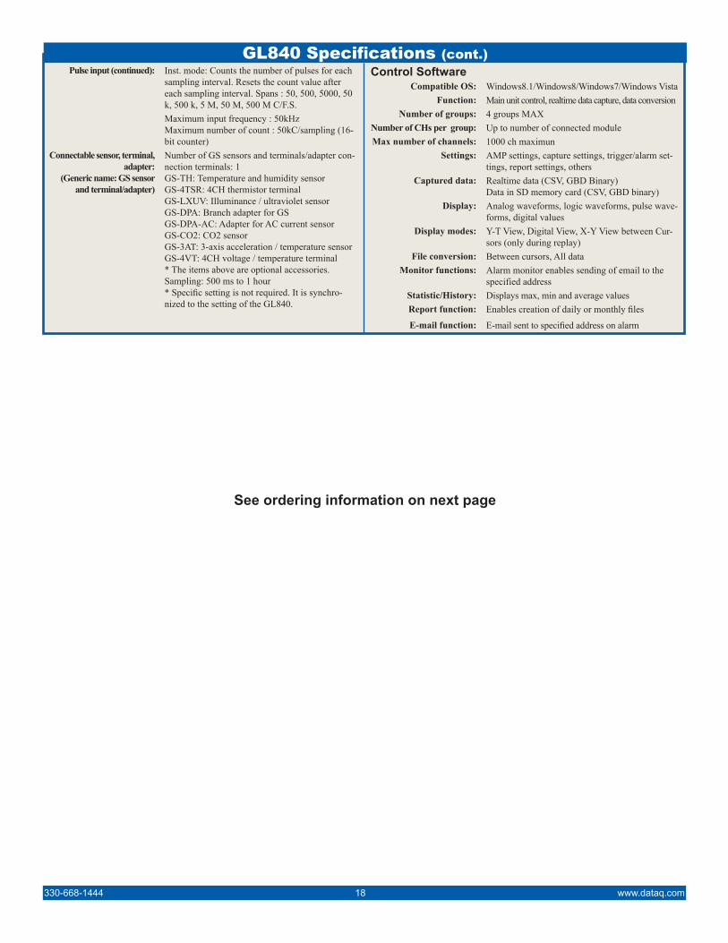
GL840 Specifications (cont.)Pulse input (continued): Inst. mode: Counts the number of pulses for each
sampling interval. Resets the count value after each sampling interval. Spans : 50, 500, 5000, 50 k, 500 k, 5 M, 50 M, 500 M C/F.S.Maximum input frequency : 50kHzMaximum number of count : 50kC/sampling (16-bit counter)
Connectable sensor, terminal, adapter:
(Generic name: GS sensor and terminal/adapter)
Number of GS sensors and terminals/adapter con-nection terminals: 1GS-TH: Temperature and humidity sensorGS-4TSR: 4CH thermistor terminalGS-LXUV: Illuminance / ultraviolet sensorGS-DPA: Branch adapter for GSGS-DPA-AC: Adapter for AC current sensorGS-CO2: CO2 sensorGS-3AT: 3-axis acceleration / temperature sensorGS-4VT: 4CH voltage / temperature terminal* The items above are optional accessories.Sampling: 500 ms to 1 hour* Specific setting is not required. It is synchro-nized to the setting of the GL840.
Control SoftwareCompatible OS: Windows8.1/Windows8/Windows7/Windows Vista
Function: Main unit control, realtime data capture, data conversionNumber of groups: 4 groups MAX
Number of CHs per group: Up to number of connected moduleMax number of channels: 1000 ch maximun
Settings: AMP settings, capture settings, trigger/alarm set-tings, report settings, others
Captured data: Realtime data (CSV, GBD Binary)Data in SD memory card (CSV, GBD binary)
Display: Analog waveforms, logic waveforms, pulse wave-forms, digital values
Display modes: Y-T View, Digital View, X-Y View between Cur-sors (only during replay)
File conversion: Between cursors, All dataMonitor functions: Alarm monitor enables sending of email to the
specified addressStatistic/History: Displays max, min and average valuesReport function: Enables creation of daily or monthly files
E-mail function: E-mail sent to specified address on alarm
330-668-1444 18 www.dataq.com
See ordering information on next page
DATAQ, the DATAQ logo and WinDaq are registered trademarks of DATAQ Instruments, Inc. All rights reserved. Copyright © DATAQ Instruments, Inc.The information on this data sheet is subject to change without notice.
DATAQ Instruments, Inc.241 Springside DriveAkron, Ohio 44333
Phone: 330-668-1444Fax: 330-666-5434
Data Acquisition Product Links(click on text to jump to page)
Data Acquisition | Data Logger
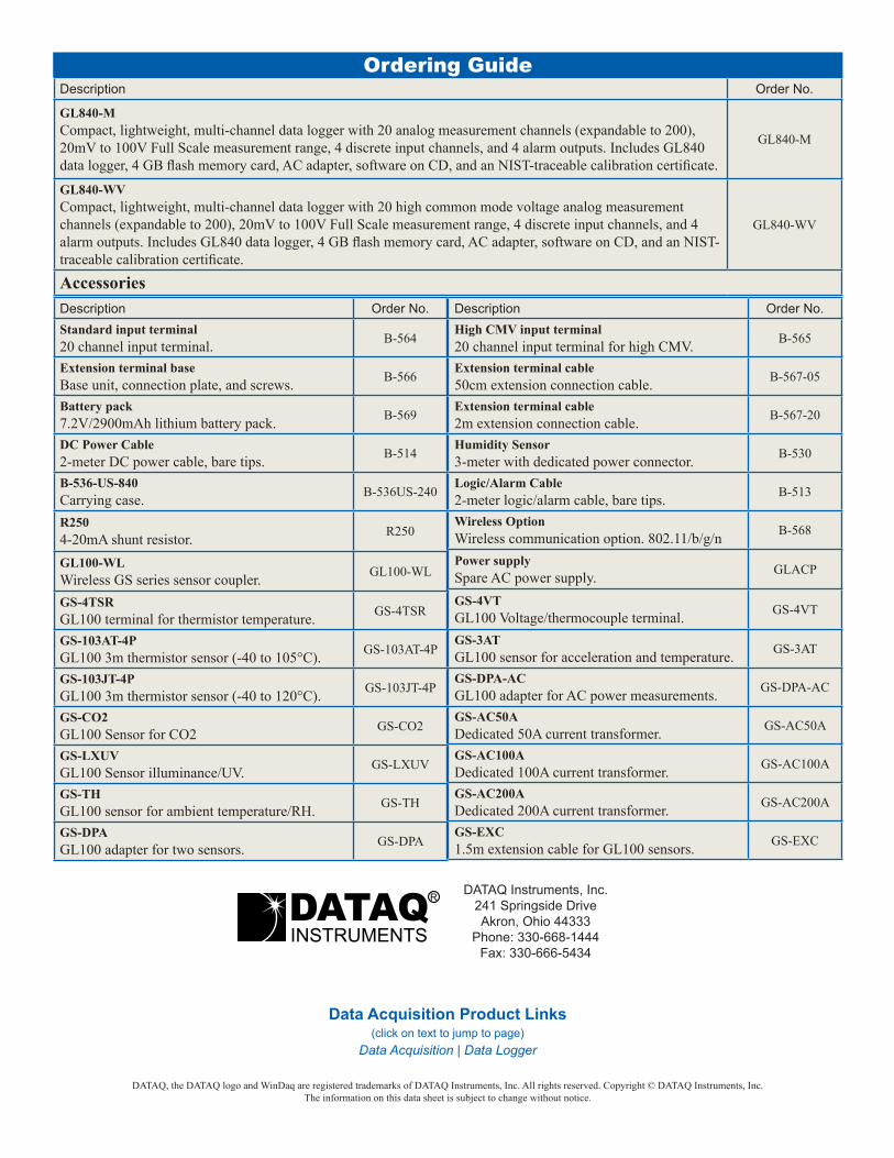
Description Order No.High CMV input terminal20 channel input terminal for high CMV. B-565
Extension terminal cable50cm extension connection cable. B-567-05
Extension terminal cable2m extension connection cable. B-567-20
Humidity Sensor3-meter with dedicated power connector. B-530
Logic/Alarm Cable2-meter logic/alarm cable, bare tips. B-513
Wireless OptionWireless communication option. 802.11/b/g/n B-568
Power supplySpare AC power supply. GLACP
GS-4VTGL100 Voltage/thermocouple terminal. GS-4VT
GS-3ATGL100 sensor for acceleration and temperature. GS-3AT
GS-DPA-ACGL100 adapter for AC power measurements. GS-DPA-AC
GS-AC50ADedicated 50A current transformer. GS-AC50A
GS-AC100ADedicated 100A current transformer. GS-AC100A
GS-AC200ADedicated 200A current transformer. GS-AC200A
GS-EXC1.5m extension cable for GL100 sensors. GS-EXC
Description Order No.Standard input terminal20 channel input terminal. B-564
Extension terminal baseBase unit, connection plate, and screws. B-566
Battery pack7.2V/2900mAh lithium battery pack. B-569
DC Power Cable2-meter DC power cable, bare tips. B-514
B-536-US-840Carrying case. B-536US-240
R2504-20mA shunt resistor. R250
GL100-WLWireless GS series sensor coupler. GL100-WL
GS-4TSRGL100 terminal for thermistor temperature. GS-4TSR
GS-103AT-4PGL100 3m thermistor sensor (-40 to 105°C). GS-103AT-4P
GS-103JT-4PGL100 3m thermistor sensor (-40 to 120°C). GS-103JT-4P
GS-CO2GL100 Sensor for CO2 GS-CO2
GS-LXUVGL100 Sensor illuminance/UV. GS-LXUV
GS-THGL100 sensor for ambient temperature/RH. GS-TH
GS-DPAGL100 adapter for two sensors. GS-DPA
Description Order No.
GL840-MCompact, lightweight, multi-channel data logger with 20 analog measurement channels (expandable to 200), 20mV to 100V Full Scale measurement range, 4 discrete input channels, and 4 alarm outputs. Includes GL840 data logger, 4 GB flash memory card, AC adapter, software on CD, and an NIST-traceable calibration certificate.
GL840-M
GL840-WVCompact, lightweight, multi-channel data logger with 20 high common mode voltage analog measurement channels (expandable to 200), 20mV to 100V Full Scale measurement range, 4 discrete input channels, and 4 alarm outputs. Includes GL840 data logger, 4 GB flash memory card, AC adapter, software on CD, and an NIST-traceable calibration certificate.
GL840-WV
Accessories
Ordering Guide