GL 2.5 - GL 4 - GL 6+ - Xplorer Motor · PDF fileMerloni TermoSanitari SpA Viale Aristide...
13
Electric Mini Tank Water heaters GL 2.5 - GL 4 - GL 6+
Transcript of GL 2.5 - GL 4 - GL 6+ - Xplorer Motor · PDF fileMerloni TermoSanitari SpA Viale Aristide...
MTS MAKES USE OFRECYCLED PAPER
029.
1.60
.542
.1.0
5 12
03 L
itogr
af s
.r.l.
Jesi
Controlled Energy Corp.340 Mad River ParkWaitsfield, VT 05673866-330-2729
www.controlledenergy.com/tech
COMMON SENSE HEAT & HOT WATER TECHNOLOGY
Merloni TermoSanitari SpAViale Aristide Merloni, 4560044 Fabriano (AN)Tel. 0732.6011Telefax. 0732.602331http://www.mtsgroup.comE-mail: [email protected]
Electric Mini TankWater heaters
GL 2.5 - GL 4 - GL 6+
The installer should review the contents of this manual with the owner uponcompletion of installation, and the manual should be left with the owner and placed ina location close to the installation.
IMPORTANT SAFETY INSTRUCTIONSWhen using electrical appliances, safety precautions to reduce the risk of fire, electricshock or injury to persons should be followed, including:
1. READ ALL INSTRUCTIONS BEFORE USING THIS WATER HEATER.2. This water heater must be grounded. Connect only to properly grounded outlet.
See “GROUNDING INSTRUCTIONS” found on “INSTALLATION INSTRUCTIONS”.3. Install or locate this water heater only in accordance with the provided installation
instructions.4. Use this water heater only for its intended use as described in this manual.5. Do not use an extension cord set with this water heater. If no outlet is available
adjacent to the water heater, contact a qualified electrician to have one properlyinstalled.
6. As with any appliance, close supervision is necessary when used by children.7. Do not operate this water heater if it is not working properly or if it has been
damaged or dropped.8. This water heater should be serviced only by qualified service personnel. Contact
a service person for examination, repair or adjustment.9. Any water heater should be installed in such a manner that if it should leak, the
resulting flow of water will not cause damage to the area in which it is installed.National Plumbing codes require a drain pan for any water heater installation.Failure to install one is the sole responsibility of owner and/or installer. ReferenceUPC 2000 (Uniform Plumbing Code) Section 510 - Protection from Damage orIPC 200 (International Plumbing Code) Section 504- Safety Devices.
KEEP THESE INSTRUCTIONS AT HANDSAVE THESE INSTRUCTIONS
WARNING
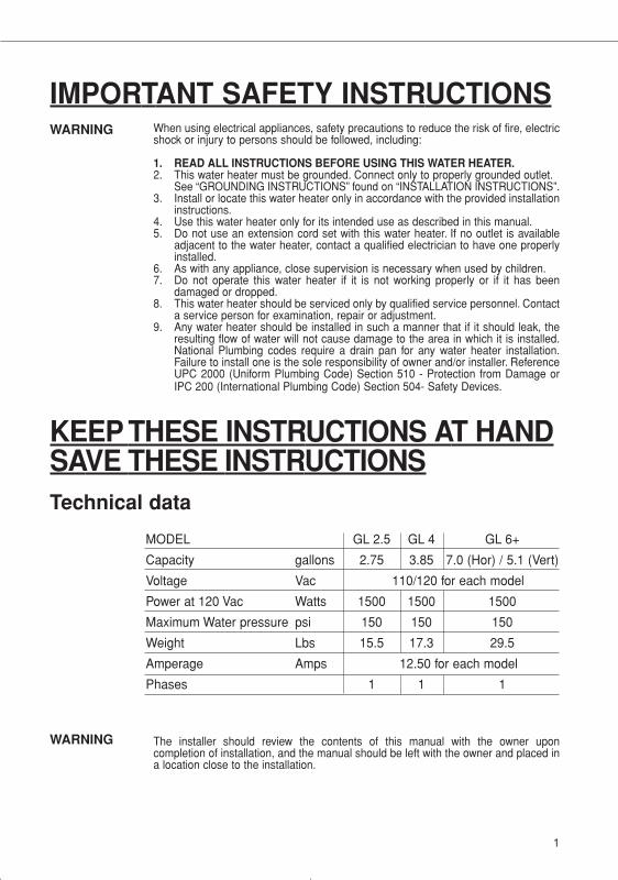
MODEL GL 2.5 GL 4 GL 6+
Capacity gallons 2.75 3.85 7.0 (Hor) / 5.1 (Vert)
Voltage Vac 110/120 for each model
Power at 120 Vac Watts 1500 1500 1500
Maximum Water pressure psi 150 150 150
Weight Lbs 15.5 17.3 29.5
Amperage Amps 12.50 for each model
Phases 1 1 1
Technical data
WARNING
1
29.1.60.542.1.04 libretto 19-01-2004 9:35 Pagina 1
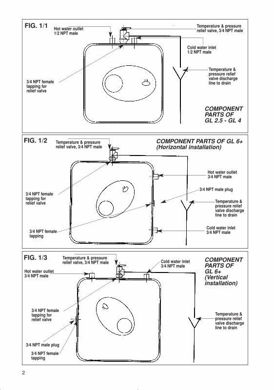
Temperature & pressurerelief valve, 3/4 NPT male
Temperature & pressurerelief valve, 3/4 NPT male
3/4 NPT femaletapping forrelief valve
3/4 NPT femaletapping
3/4 NPT femaletapping
3/4 NPT femaletapping forrelief valve
Hot water outlet1/2 NPT male
3/4 NPT femaletapping forrelief valve
FIG. 1/1 Temperature & pressurerelief valve, 3/4 NPT male
Cold water inlet1/2 NPT male
Temperature &pressure reliefvalve dischargeline to drain
COMPONENTPARTS OFGL 2.5 - GL 4
COMPONENTPARTS OFGL 6+(Verticalinstallation)
COMPONENT PARTS OF GL 6+(Horizontal installation)
FIG. 1/2
FIG. 1/3
Temperature &pressure reliefvalve dischargeline to drain
Hot water outlet3/4 NPT male
Hot water outlet3/4 NPT male
3/4 NPT male plug
3/4 NPT male plug
Temperature &pressure reliefvalve dischargeline to drain
Cold water inlet3/4 NPT male
Cold water inlet3/4 NPT male
2
29.1.60.542.1.04 libretto 19-01-2004 9:35 Pagina 2
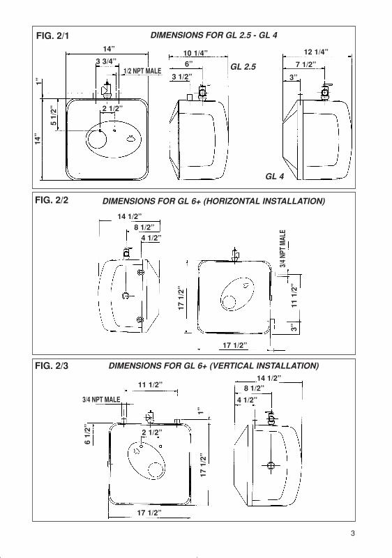
FIG. 2/1 DIMENSIONS FOR GL 2.5 - GL 4
DIMENSIONS FOR GL 6+ (HORIZONTAL INSTALLATION)
DIMENSIONS FOR GL 6+ (VERTICAL INSTALLATION)
FIG. 2/2
FIG. 2/3
3
GL 2.5
GL 4
14” 10 1/4” 12 1/4”
7 1/2”
3”
6”
3 1/2”
1”14
”
51/
2”3 3/4”
2 1/2”
14 1/2”8 1/2”
4 1/2”
17 1/2”
14 1/2”8 1/2”
4 1/2”
11 1/2”
17 1/2”
17 1
/2”
17 1
/2”
11 1
/2”
3/4
NPT
MAL
E
3”
1”
1/2 NPT MALE
3/4 NPT MALE
2 1/2”
6 1/
2”
29.1.60.542.1.04 libretto 19-01-2004 9:35 Pagina 3
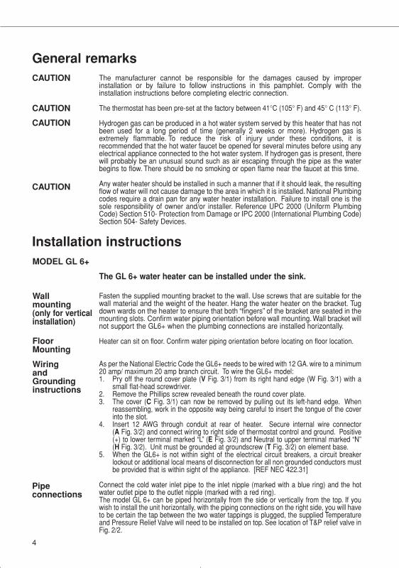
General remarksThe manufacturer cannot be responsible for the damages caused by improperinstallation or by failure to follow instructions in this pamphlet. Comply with theinstallation instructions before completing electric connection.
The thermostat has been pre-set at the factory between 41°C (105° F) and 45° C (113° F).
Hydrogen gas can be produced in a hot water system served by this heater that has notbeen used for a long period of time (generally 2 weeks or more). Hydrogen gas isextremely flammable. To reduce the risk of injury under these conditions, it isrecommended that the hot water faucet be opened for several minutes before using anyelectrical appliance connected to the hot water system. If hydrogen gas is present, therewill probably be an unusual sound such as air escaping through the pipe as the waterbegins to flow. There should be no smoking or open flame near the faucet at this time.
Any water heater should be installed in such a manner that if it should leak, the resultingflow of water will not cause damage to the area in which it is installed. National Plumbingcodes require a drain pan for any water heater installation. Failure to install one is thesole responsibility of owner and/or installer. Reference UPC 2000 (Uniform PlumbingCode) Section 510- Protection from Damage or IPC 2000 (International Plumbing Code)Section 504- Safety Devices.
CAUTION
CAUTION
CAUTION
CAUTION
Installation instructions
Fasten the supplied mounting bracket to the wall. Use screws that are suitable for thewall material and the weight of the heater. Hang the water heater on the bracket. Tugdown wards on the heater to ensure that both “fingers” of the bracket are seated in themounting slots. Confirm water piping orientation before wall mounting. Wall bracket willnot support the GL6+ when the plumbing connections are installed horizontally.
Heater can sit on floor. Confirm water piping orientation before locating on floor location.
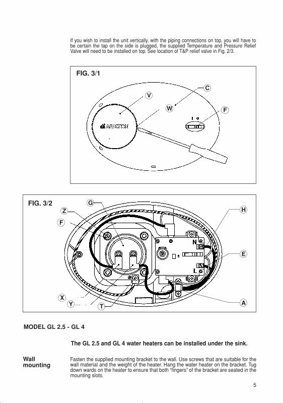
As per the National Electric Code the GL6+ needs to be wired with 12 GA. wire to a minimum20 amp/ maximum 20 amp branch circuit. To wire the GL6+ model:1. Pry off the round cover plate (V Fig. 3/1) from its right hand edge (W Fig. 3/1) with a
small flat-head screwdriver.2. Remove the Phillips screw revealed beneath the round cover plate.3. The cover (C Fig. 3/1) can now be removed by pulling out its left-hand edge. When
reassembling, work in the opposite way being careful to insert the tongue of the coverinto the slot.
4. Insert 12 AWG through conduit at rear of heater. Secure internal wire connector(A Fig. 3/2) and connect wiring to right side of thermostat control and ground. Positive(+) to lower terminal marked “L” (E Fig. 3/2) and Neutral to upper terminal marked “N”(H Fig. 3/2). Unit must be grounded at groundscrew (T Fig. 3/2) on element base.
5. When the GL6+ is not within sight of the electrical circuit breakers, a circuit breakerlockout or additional local means of disconnection for all non grounded conductors mustbe provided that is within sight of the appliance. [REF NEC 422.31]
Connect the cold water inlet pipe to the inlet nipple (marked with a blue ring) and the hotwater outlet pipe to the outlet nipple (marked with a red ring).The model GL 6+ can be piped horizontally from the side or vertically from the top. If youwish to install the unit horizontally, with the piping connections on the right side, you will haveto be certain the tap between the two water tappings is plugged, the supplied Temperatureand Pressure Relief Valve will need to be installed on top. See location of T&P relief valve inFig. 2/2.
Wallmounting(only for verticalinstallation)
MODEL GL 6+
WiringandGroundinginstructions
Pipeconnections
FloorMounting
The GL 6+ water heater can be installed under the sink.
4
29.1.60.542.1.04 libretto 19-01-2004 9:35 Pagina 4
MODEL GL 2.5 - GL 4
The GL 2.5 and GL 4 water heaters can be installed under the sink.
Fasten the supplied mounting bracket to the wall. Use screws that are suitable for thewall material and the weight of the heater. Hang the water heater on the bracket. Tugdown wards on the heater to ensure that both “fingers” of the bracket are seated in themounting slots.
Wallmounting
FIG. 3/2 GH
E
A
Z
F
XY T
FIG. 3/1
VC
FW
If you wish to install the unit vertically, with the piping connections on top, you will have tobe certain the tap on the side is plugged, the supplied Temperature and Pressure ReliefValve will need to be installed on top. See location of T&P relief valve in Fig. 2/3.
5
29.1.60.542.1.04 libretto 19-01-2004 9:35 Pagina 5
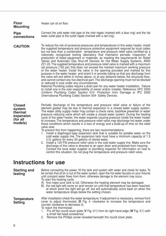
Heater can sit on floor.
Connect the cold water inlet pipe to the inlet nipple (marked with a blue ring) and the hotwater outlet pipe to the outlet nipple (marked with a red ring).
To reduce the risk of excessive pressures and temperatures in this water heater, installthe supplied temperature and pressure protective equipment required by local codesbut not less than a combination temperature and pressure relief valve certified by anationally recognized testing laboratory that maintains periodic inspection ofproduction of listed equipment or materials, as meeting the requirements for ReliefValves and Automatic Gas Shut-off Devices for Hot Water Supply Systems, ANSIZ21.22.The supplied temperature and pressure relief valve is marked with a maximumset pressure (150 psi) that does not exceed the marked maximum working pressureof the water heater. Install the valve in the opening provided and marked for thispurpose in the water heater, and orient it or provide tubing so that any discharge fromthe valve will exit within 6 inches above, or at any distance below, the structural floor,and cannot contact any live electrical part. The discharge opening must not be blockedor reduced in size under any circumstances.National Plumbing codes require a drain pan for any water heater installation. Failureto install one is the sole responsibility of owner and/or installer. Reference UPC 2000(Uniform Plumbing Code) Section 510- Protection from Damage or IPC 2000(International Plumbing Code) Section 504- Safety Devices.
Periodic discharge of the temperature and pressure relief valve or failure of theelement gasket may be due to thermal expansion in a closed water supply system.The water utility supply meter may contain a check valve, backflow preventer or waterpressure reducing valve which will create a closed water system. During the heatingcycle of the water heater, the water expands causing pressure inside the water heaterto increase. The temperature and pressure relief valve may discharge hot water underthese conditions which results in a loss of energy and a build-up of lime on the reliefvalve seat.To prevent this from happening, there are two recommendations:1. Install a diaphragm-type expansion tank that is suitable for potable water on the
cold water supply line. The expansion tank must have a minimum capacity of 1.5U.S. gallons for every 50 gallons of stored water.
2. Install a 125 PSI pressure relief valve in the cold water supply line. Make sure thedischarge of this valve is directed to an open drain and protected from freezing.Contact the local water supplier or plumbing inspector for information on how tocontrol this situation. Do not plug the temperature and pressure relief valve.
Instructions for useBefore connecting the power, fill the tank and system with water and check for leaks. Tobe certain that all air is out of the water system, open the hot water faucets on your fixturesuntil constant water flows from them, otherwise damage to the element may occur.To start the heating cycle:A) first make sure tank is full. Otherwise the heating element may be damaged.B) the red light will come on and remain on until that temperature has been reached,
at which point the light will go off, but will automatically come back on when thewater temperature drops below the setting chosen.
After installation check the water temperature. If adjustment is necessary, remove frontcover to adjust thermostat (D Fig. 4 -clockwise to increase the temperature andcounter clockwise to decrease it).To reach the thermostat:1. Pry off the round cover plate (V Fig. 3/1) from its right hand edge (W Fig. 3/1) with
a small flat-head screwdriver.2. Remove the Phillips screw revealed beneath the round cover plate.
CAUTION
Closedsystemthermalexpansion(for allmodels)
Starting and testing
TemperatureSetting
6
Pipeconnections
FloorMounting
29.1.60.542.1.04 libretto 19-01-2004 9:35 Pagina 6
Maintenance instructionsNote: Do not attempt to repair this water heater yourself. Call a service person
for assistance. Always turn off the power supply to the heater prior toservicing or draining the heater.
Periodic maintenanceNote: For most of these operations, the water will have to be drained from the heater.
For all of these operations the power supply needs to be shut off and the frontcover removed.
1. Pry off the round cover plate (V Fig. 3/1) from its right hand edge (WFig. 3/1) with a small flat-head screwdriver.
2. Remove the Phillips screw revealed beneath the round cover plate.
3. The cover (C Fig. 3/1) can now be removed by pulling out its left-handedge. When reassembling, work in the opposite way being careful toinsert the tongue of the cover into the slot.
1) If the heater has been installed with flexible hoses, shut off the power supply andturn the heater upside down over a sink to drain the water out of it, OR
2) If the heater has been installed with rigid piping, siphon the water out through any(lower) service valve on the (inlet side). Keep a hot water faucet open whilesiphoning the water out, OR
3) If the heater has been installed with flexible hoses, it can also be emptied bysiphoning through the inlet side hose. Keep a hot water faucet open whilesiphoning.
7
Drainingthe Heater
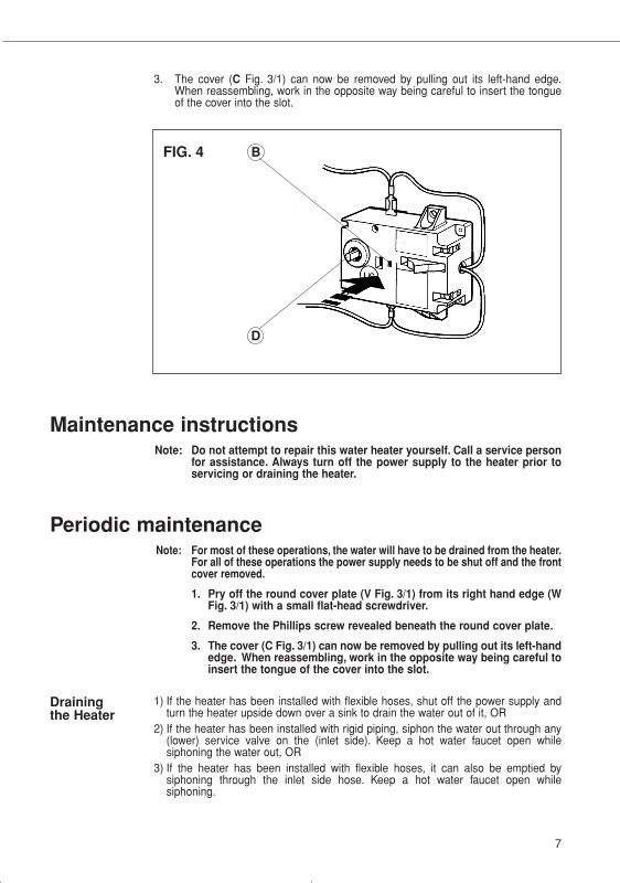
FIG. 4
D
B
3. The cover (C Fig. 3/1) can now be removed by pulling out its left-hand edge.When reassembling, work in the opposite way being careful to insert the tongueof the cover into the slot.
29.1.60.542.1.04 libretto 19-01-2004 9:35 Pagina 7
Changingthe anoderod
REPLACEMENT OF PARTS
B) Once the element has dried up, use a soft brush (non metallic to prevent damagingthe stainless steel sheath) on element. Brush the dried mineral off. Reinstall theelement with gasket and make the wire connections.
C) Replace anode rod (N Fig. 5/2) if it is noticeably deteriorated or considerablyshorter then seen in figure 5/2.
WARNING: make sure the tank has been refilled with water before restoring power.
The anode rod (N fig. 5/2) helps protect the tank against corrosion. Depending on thewater condition, the magnesium anode rod may need to be changed every year or so.Galvanic and electrolytic corrosion can destroy a tank if the anode rod is “spent”.Rusty water is usually an indication of a “spent” anode rod. If rusty water is present,examine anode rod immediately. Rapid degradation of the anode rod (less than 1year) may indicate the presence of galvanic corrosion due to “stray” direct current. Inthis case, it may be necessary to add a “grounding strap” from the Ariston tank to thecopper plumbing.
1. Turn off the power supply and drain the heater (see Draining the Heater).2. Remove heating element (see previous section).3. Remove and replace the anode rod N Fig. 5/2.4. Refill tank with water before restoring power.
Removingthe heatingelement
Descalingthe heatingelement
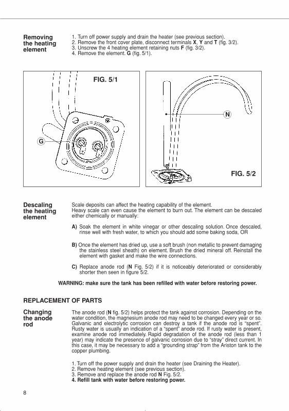
1. Turn off power supply and drain the heater (see previous section).2. Remove the front cover plate, disconnect terminals X, Y and T (fig. 3/2).3. Unscrew the 4 heating element retaining nuts F (fig. 3/2).4. Remove the element. G (fig. 5/1).
Scale deposits can affect the heating capability of the element.Heavy scale can even cause the element to burn out. The element can be descaledeither chemically or manually:
A) Soak the element in white vinegar or other descaling solution. Once descaled,rinse well with fresh water, to which you should add some baking soda, OR
G
FIG. 5/1
N
FIG. 5/2
8
29.1.60.542.1.04 libretto 19-01-2004 9:35 Pagina 8
9
Water doesnot get hot
Light not on
Brown water
Odor in water
Water is toohot
Water nothot enough
Leaking
Troubleshooting1. Make sure the power supply is on and working.2. If light does not come on, check that the reset button is pushed in; follow steps from
previous section.3. If the indicator light works properly but temperature does not get hot a tap, test for
a plumbing crossover; shut off cold supply to heater and open hot water tap. Thereshould be no water flowing. Any continued flow indicates a crossover which willeffect the temperature and will need to be corrected.
4. Replace heating element (see previous section on changing the heating element).
1. If the light does not come on, but water gets hot, check for faulty bulb.2. Check reset button; follow steps from previous section.
1. Brown or rusty water indicates a “spent” anode rod. Replace anode rod.
1. Smelly water could be due to an unusual reaction between local water and theheater’s anode rod. Check anode rod (see section on changing the anode rod).
1. Remove cover plate and turn the temperature selector dial (D Fig. 4) counterclockwise to lower temperature. If temperature never lowers then replacethermostat. (see section on changing the thermostat).
1. Under Instructions for Use see Temperature Setting instruction.
1. Check water fittings and T & P fitting on top of tank.2. Remove front cover and inspect heating element gasket.
Occasionally, the high temperature limit shut off device may trigger and shut thesystem down. This occurs when water temperature exceeds 190° F and shuts offpower to the heating element. The shut off device may also trigger from a poweroutage or electrical storm.
To reach the thermostat:1. Pry off the round cover plate (V Fig. 3/1) from its right hand edge (W Fig. 3/1) with
a small flat-head screwdriver.2. Remove the Phillips screw revealed beneath the round cover plate.3. The cover (C Fig. 3/1) can now be removed by pulling out its left-hand edge. When
reassembling, work in the opposite way being careful to insert the tongue of thecover into the slot.
4. Firmly press reset button (B Fig. 4). Reconnect power.5. IMPORTANT: Check the operation of the thermostat, turn temperature dial from
high to low, if the red light does not go off on low setting, turn off power supply andcall a service person to replace the thermostat.
6. If the system works, place dial setting to desired setting. Note: a lower setting ismore economical and reduces the risk of scalding. Replace cover plate.
CAUTION: Call a technician if the high limit needs to be reset frequently.
ResettingHigh LimitSwitch
1. Turn off power supply and drain the heater (see Draining the Heater).2. Remove the heating element (see section on Removing the Heating Element).3. Install new element with gasket, making sure the gasket and element are positioned
correctly. Tighten the retaining nuts and make the wire connections.4. Refill tank with water before restoring power.
1. Turn off power supply.2. Disconnect the 2 push/pull type wires on thermostat.3. Loosen the two brass screws at right side of thermostat and pull wires out.4. Unscrew and remove the two phillips screws holding the thermostat down.5. Install new thermostat and re-attach wiring and screws.
Changingthe heatingelement
Changingthethermostat
29.1.60.542.1.04 libretto 19-01-2004 9:35 Pagina 9
10
29.1.60.542.1.04 libretto 19-01-2004 9:35 Pagina 10
ARISTON • LIMITED 6 YEARS WARRANTYCOVERAGEARISTON, THROUGH ITS U.S. DISTRIBUTORCONTROLLED ENERGY CORP., (hereinafterCEC) guarantees this water heater to theOwner (hereinafter “Owner”) of the water heaterat the original installation location againstdefects in material and workmanship for theperiods specified below.
WARRANTY PERIOD1. The inner Tank - If the inner tank leaks withinsix (6) years from the date of original installationof the water heater, because of a defect inmaterial or workmanship, CEC will furnish tosuch Owner a new heater of the then prevailingcomparable model.
2. Any Component Part Other than TheOriginal Inner Tank - If any component part(other than the inner tank) proven to bedefective in material or workmanship within one(1) year from the date of original installation ofthe water heater, CEC will furnish the Ownerwith a replacement of the defective part(s).
3. Verification of Date of Original Installation- When Owner cannot verify or document theoriginal date of installation, the warranty periodbegins on the date of manufacture marked onthe tag affixed to the water heater.
EXCLUSIONS1. THIS LIMITED WARRANTY SHALL BE THEEXCLUSIVE WARRANTY MADE BY THEMANUFACTURER AND IS MADE IN LIEU OFALL OTHER WARRANTIES, EXPRESSED ORIMPLIED (WHETHER WRITTEN OR ORAL),INCLUDING, BUT NOT LIMITED TO,WARRANTIES OF MERCHANTABILITY ANDFITNESS FOR A PARTICULAR PURPOSE.
2. The Manufacturer shall not be liable for anyincidental, consequential, special or contingentdamages or expenses arising, directly orindirectly, from any defect in the water heater orthe use of the water heater.
3. The Manufacturer shall not be liable for anywater damage arising, directly or indirectly, fromany defect in the water heater componentpart(s) or from its use.
4. Manufacturer shall not be liable under thiswarranty if:
a) The water heater or any of its componentparts has been subject to misuse, alteration,neglect or accident, orb) The water heater has not been installed inaccordance with the applicable localplumbing and/or building code(s) and/orregulation(s), orc) The water heater has not been installed inaccordance with the printed manufacturer’sinstructions, ord) The water heater is not continuously
supplied with potable water.
5. The OWNER and not the Manufacturer or hisrepresentative shall be liable for and shall payfor all field charges for labor or other expensesincurred in the removal and/or repair of theproduct or any expense incurred by the ownerin order to repair the product.SOME STATES DO NOT ALLOW THEEXCLUSION OR LIMITATION OF INCIDENTALOR CONSEQUENTIAL DAMAGES, SO THEABOVE LIMITATION OR EXCLUSION MAYNOT APPLY TO YOU. THIS WARRANTYGIVES YOU SPECIFIC LEGAL RIGHTS ANDYOU MAY ALSO HAVE OTHER RIGHTSWHICH MAY VARY FROM STATE TO STATE.
IMPORTANT: OWNER SHALL KEEP THISMAKE A CLAIM
NOTE: A water heater should be installed insuch a manner that if it should leak, the
resulting flow of water will not cause damageto the area in which it is installed.
HOW THE OWNER CAN SECURE SERVICEOR MAKE A CLAIM
1. Owner should contact the dealer who soldthe water heater covered by this warranty or2. Owner should submit the warranty claimdirectly to CEC at the address listed below, andthey will arrange for the handling of the claim3. Whenever any inquiry or service request ismade, be sure to include the water heatermodel number the date of manufacture , date ofinstallation, Dealer’s name and the watts andvoltage.4. When returning the water heater orcomponent part(s), they must be individuallytagged and identified with the Returned GoodsAuthorization # issued by CEC and shippedprepaid to CEC at the address below.
Controlled Energy Corp.340 Mad River ParkWaitsfield, VT 05673866-330-2729
COMMON SENSE HEAT & HOT WATER TECHNOLOGY
www.controlledenergy.com/tech
29.1.60.542.1.04 libretto 19-01-2004 9:35 Pagina 11

MTS MAKES USE OFRECYCLED PAPER
029.
1.60
.542
.1.0
5 12
03 L
itogr
af s
.r.l.
Jesi
Controlled Energy Corp.340 Mad River ParkWaitsfield, VT 05673866-330-2729
www.controlledenergy.com/tech
COMMON SENSE HEAT & HOT WATER TECHNOLOGY
Merloni TermoSanitari SpAViale Aristide Merloni, 4560044 Fabriano (AN)Tel. 0732.6011Telefax. 0732.602331http://www.mtsgroup.comE-mail: [email protected]
Electric Mini TankWater heaters
GL 2.5 - GL 4 - GL 6+