
HDR 650 Installation and Operations Manual HDR 650 Installation ...
Upload
phungnguyetCategory
view
216download
0
International Journal of Computer Graphics & Animation (IJCGA) Vol.4, No.4, October 2014
DOI : 10.5121/ijcga.2014.4401 1
GHOST AND NOISE REMOVAL IN EXPOSURE FUSION
FOR HIGH DYNAMIC RANGE IMAGING
Dong-Kyu Lee
1, Rae-Hong Park
1 and Soonkeun Chang
2
1Department of Electronic Engineering, School of Engineering, Sogang University,
35 Baekbeom-ro (Sinsu-dong), Mapo-gu, Seoul 121-742, Korea 2Samsung Electronics Co., Ltd., Suwon, Gyeonggi-do 443-742, Korea
ABSTRACT
For producing a single high dynamic range image (HDRI), multiple low dynamic range images (LDRIs)
are captured with different exposures and combined. In high dynamic range (HDR) imaging, local motion
of objects and noise in a set of LDRIs can influence a final HDRI: local motion of objects causes the ghost
artifact and LDRIs, especially captured with under-exposure, make the final HDRI noisy. In this paper, we
propose a ghost and noise removal method for HDRI using exposure fusion with subband architecture, in
which Haar wavelet filter is used. The proposed method blends weight map of exposure fusion in the
subband pyramid, where the weight map is produced for ghost artifact removal as well as exposure fusion.
Then, the noise is removed using multi-resolution bilateral filtering. After removing the ghost artifact and
noise in subband images, details of the images are enhanced using a gain control map. Experimental
results with various sets of LDRIs show that the proposed method effectively removes the ghost artifact and
noise, enhancing the contrast in a final HDRI.
KEYWORDS
High Dynamic Range Imaging, Exposure Fusion, Ghost Removal, Noise Removal
1. INTRODUCTION
Digital sensors and display devices such as digital camera, television, etc., have a limited
dynamic range. They cannot capture and display the full dynamic range with which people can
perceive a real world scene. For example, when a scene in which bright and dark regions coexist
is captured, these regions tend to be under- or over-saturated because of the limited dynamic
range. The dynamic range is one of the important criteria for evaluating image quality, especially
in devices supporting high resolution images. Images and display devices supporting high
dynamic range (HDR) are attractive to producers and customers of today.
In order to acquire a HDR image (HDRI), HDR imaging techniques were proposed [1–5].
Multiple low dynamic range images (LDRIs) are captured with multiple exposures using auto
exposure bracketing of a camera. Then, captured LDRIs are combined into a single HDRI by
HDR imaging. However, when LDRIs are combined, several problems can occur due to global
and local motions [6–9] of a camera or an object, and noise [10–12] in LDRIs. The ghost artifact
and noise are major problems in HDR imaging. Since HDRI is generated from multiple images,
moving camera or object causes the ghost artifact. HDR imaging is generally used for high-
quality image even in the low-light or back-light condition in which captured images tend to have
much noise due to camera setting with short-exposure time or high sensitivity. Therefore, the
noise is also one of the critical issues in HDR imaging.
International Journal of Computer Graphics & Animation (IJCGA) Vol.4, No.4, October 2014
2
HDR imaging can be generally classified into two approaches. In the first approach, HDR
imaging [1–3] consists of radiance map generation and tone-mapping. First, a HDR radiance map,
which covers the entire dynamic range of LDRIs, is generated [1]. Generally, in this radiance map
generation process, the ghost artifact due to local motion and noise are removed [2, 3, 11]. Then,
the radiance-map is tone-mapped back to a LDR representation to fit the range of display or
printing devices [13]. The second approach is image fusion, where LDRIs are blended directly
into a single HDRI using weight map [4, 5, 14–17]. To remove the ghost artifact due to local
motion and noise, the weight map is computed using image quality measures such as ghost and
noise as well as contrast, well-exposedness, and saturation.
In this paper, we propose a ghost and noise removal method using exposure fusion for HDR
imaging. In the proposed method, exposure fusion is used in the subband architecture, where
exposure fusion blends directly LDRIs using the weight map guided by quality measures for
HDR effect. To generate motion maps for removing ghost artifact, the proposed histogram based
motion maps [18] are used, where the motion maps are combined with the weight maps of
exposure fusion. Fused subband images are denoised by multi-resolution bilateral filtering [19],
which is very effective in removing noise. After denoising, details of the subband images are
enhanced through the gain control [20]. Next, detail-preserved subband images are reconstructed
to a single final fused image.
The rest of the paper is organized as follows. In Section 2, image fusion for HDR imaging, ghost
removal methods, and noise reduction methods in HDR imaging are reviewed. Section 3 proposes
an exposure fusion method using subband architecture. In this section, the proposed histogram
based ghost removal method, noise reduction method, and gain control method in subband
architecture are described. Experimental results of the proposed and existing ghost and noise
removal methods for HDR imaging are compared and discussed in Section 4. Finally, Section 5
concludes the paper.
2. PREVIOUS WORK
To get a single HDRI, LDRIs are captured by exposure bracketing in a camera and combined in
HDR imaging [1–5]. However, image quality is rather degraded in HDR imaging unless some
artifacts such as ghost artifact and noise are reduced. In this section, we review previous work on
HDR imaging, ghost removal, and noise reduction.
2.1. Image Fusion for HDR Imaging
Image fusion for HDR imaging skips the process of generating an HDR radiance map, and
directly fuses a set of multi-exposed images to a single HDRI [4]. It measures the quality of each
pixel in LDRIs and computes weighted average guided by quality measures for high-quality
image. It has several advantages that it is implemented in a simple acquisition pipeline and does
not require to know exposure times of every LDRI and to calculate the camera response curve
with the exposure times. Compared with the case in which a single image is used for HDR
imaging [21], image fusion enhances better contrast and dynamic range because more
information such as contrast, detail, and structure in the images can be used.
Goshtasby [4] proposed a block-based fusion method for HDR imaging. This method selects
blocks that contain the most information within that block and then the selected blocks are
blended together using blending function that is defined by rational Gaussian. Raman and
International Journal of Computer Graphics & Animation (IJCGA) Vol.4, No.4, October 2014
Chaudhuri [15] proposed a bilateral filter based composition method. They computed the
difference between LDRIs and the bilateral filtered image, and designed weight function using
the difference, where weak edges and textures are given high weight values to preserve detail.
et al. [22] proposed a layered-based fusion algorithm. They used a global
robustness and color consistency
Bertalmio and Levine [23] introduce
measured the difference in edge information in the short
difference in the long-exposure image
In exposure fusion [5], quality measures for contrast, saturation, and well
compute the weight maps for each LDRI. Then, the weight map and LDRIs are fused using
Gaussian and Laplacian pyramid decomposition, respectively. Shen
preserving exposure fusion. They applied the exposure fusion [5] to subband architecture using
quadrature mirror filter (QMF), in which the gain control strategy
details in HDRI.
2.2. Ghost Artifact Removal
Ghost artifact is due to global motion of a camera and local motion of objects in a scene. Even
though image registration [6, 25
ghost artifact still remains due to local motion of objects, because LDRIs are not
simultaneously and moving objects can be located at different positions during taking LDRIs.
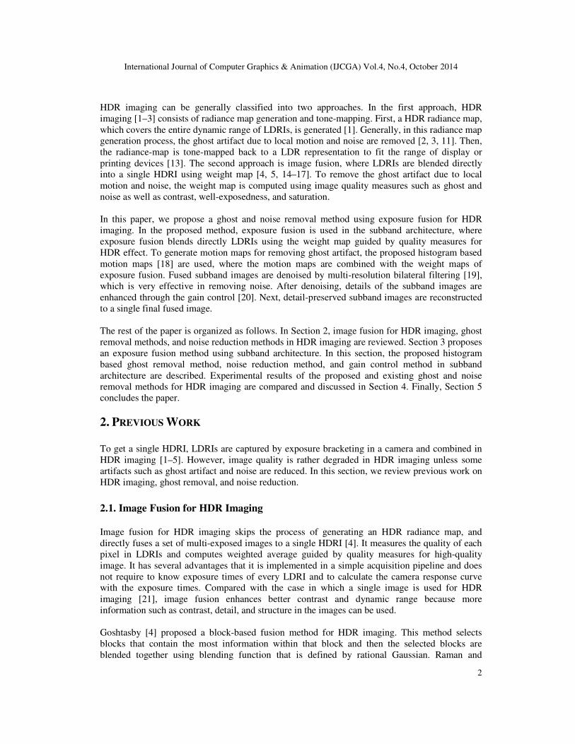
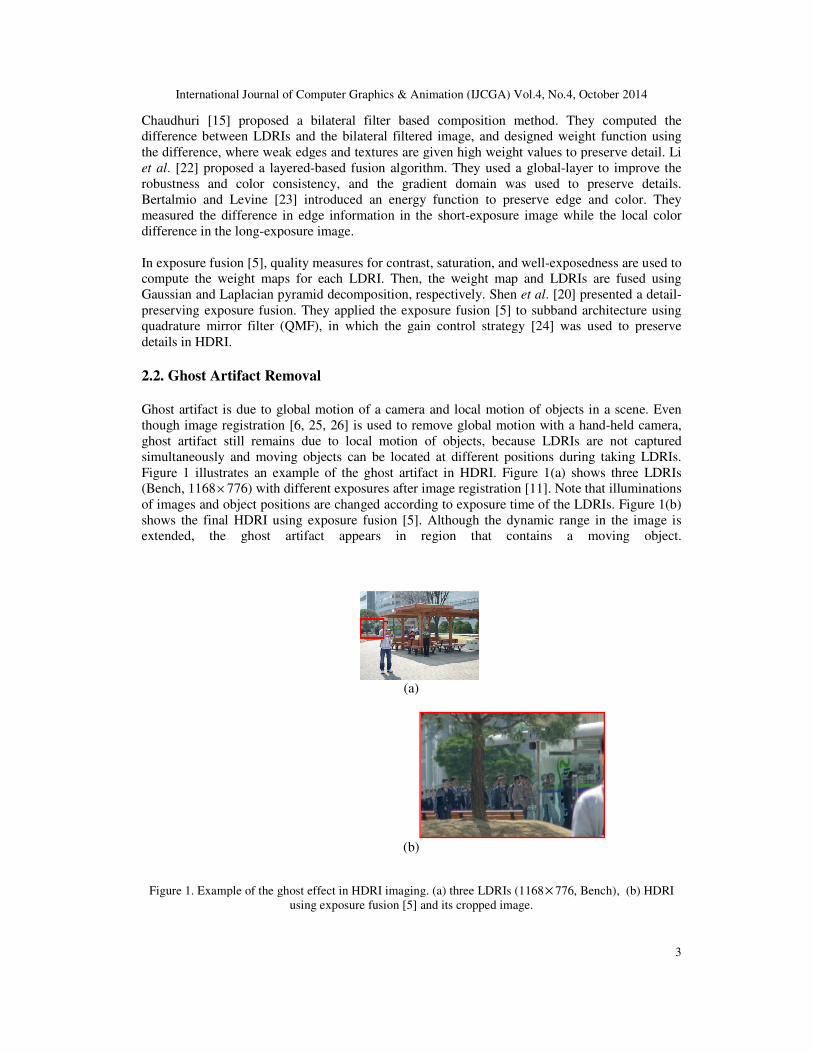
Figure 1 illustrates an example of the ghost artifact in HDRI. Fig
(Bench, 1168× 776) with different exposu
of images and object positions are changed according to exposure time of the LDRIs. Fig
shows the final HDRI using exposure fusion [5]. Although the dynamic range in the image is
extended, the ghost artifact appears in region that contains a moving object.
Figure 1. Example of the ghost effect in HDRI imaging. (a) three LDRIs (1168
using exposure fusion [
International Journal of Computer Graphics & Animation (IJCGA) Vol.4, No.4, October 2014
] proposed a bilateral filter based composition method. They computed the
difference between LDRIs and the bilateral filtered image, and designed weight function using
where weak edges and textures are given high weight values to preserve detail.
based fusion algorithm. They used a global-layer to improve the
consistency, and the gradient domain was used to preserve
introduced an energy function to preserve edge and
measured the difference in edge information in the short-exposure image while the local color
exposure image.
, quality measures for contrast, saturation, and well-exposedness are used to
compute the weight maps for each LDRI. Then, the weight map and LDRIs are fused using
Gaussian and Laplacian pyramid decomposition, respectively. Shen et al. [20] presented a det
preserving exposure fusion. They applied the exposure fusion [5] to subband architecture using
quadrature mirror filter (QMF), in which the gain control strategy [24] was used to preserve
Ghost Artifact Removal
due to global motion of a camera and local motion of objects in a scene. Even
5, 26] is used to remove global motion with a hand-
artifact still remains due to local motion of objects, because LDRIs are not
simultaneously and moving objects can be located at different positions during taking LDRIs.
1 illustrates an example of the ghost artifact in HDRI. Figure 1(a) shows three LDRIs
different exposures after image registration [11]. Note that illuminations
of images and object positions are changed according to exposure time of the LDRIs. Fig
shows the final HDRI using exposure fusion [5]. Although the dynamic range in the image is
the ghost artifact appears in region that contains a moving object.
(a)
(b)
. Example of the ghost effect in HDRI imaging. (a) three LDRIs (1168× 776, Bench
using exposure fusion [5] and its cropped image.
International Journal of Computer Graphics & Animation (IJCGA) Vol.4, No.4, October 2014
3
] proposed a bilateral filter based composition method. They computed the
difference between LDRIs and the bilateral filtered image, and designed weight function using
where weak edges and textures are given high weight values to preserve detail. Li
layer to improve the
, and the gradient domain was used to preserve details.
an energy function to preserve edge and color. They
exposure image while the local color
exposedness are used to
compute the weight maps for each LDRI. Then, the weight map and LDRIs are fused using
] presented a detail-
preserving exposure fusion. They applied the exposure fusion [5] to subband architecture using
was used to preserve
due to global motion of a camera and local motion of objects in a scene. Even
-held camera,
artifact still remains due to local motion of objects, because LDRIs are not captured
simultaneously and moving objects can be located at different positions during taking LDRIs.
1(a) shows three LDRIs
. Note that illuminations
of images and object positions are changed according to exposure time of the LDRIs. Figure 1(b)
shows the final HDRI using exposure fusion [5]. Although the dynamic range in the image is
the ghost artifact appears in region that contains a moving object.
, Bench), (b) HDRI
International Journal of Computer Graphics & Animation (IJCGA) Vol.4, No.4, October 2014
4
To generate the motion map, region with large intensity change can be simply considered as
region of object motion. However, LDRIs are captured with different exposure times, thus this
method is not directly applicable to HDR imaging and the illumination change between LDRIs
should be considered. Therefore, the removal method of the ghost artifact caused by local motion
uses the property, which is not sensitive to exposure time, such as variance, entropy, and
histogram between LDRIs.
To detect object motion, a variance based method [2] uses the weighted variance of pixel values
between multiple-exposure LDRIs and divides images by thresholding into two regions: motion
region and background. On the other hand, Jacobs et al. [3] used the difference of local entropy
between multiple-exposure LDRIs to detect motion region. The measure using the difference of
local entropy is effective for detecting the features such as intensity edges and corners regardless
of exposures. However, it is sensitive to parameter values used to define motion and to the
window size for the local entropy. Khan et al. [27] proposed the ghost artifact removal method
based on the kernel density estimator. They computed the probability that the pixel is contained in
the background and used the probability as a weighting factor for constructing the radiance map.
Jia and Tang [28] used a voting method for color/intensity correction of input images. In this
method, global and local replacement functions are iteratively estimated using intensity values in
voting space and the replacement functions are employed to detect occlusion which causes ghost
artifact. While this method gives a high contrast image from defective input images with global
and local alignment, the computational load is high because of optimization process for
computing the replacement function.
Histogram based methods [7, 11] classify the intensity values into multi-levels. They regard the
region with large difference between the level indices as motion region. The computational load
of the methods is relatively low, however they excessively detect wrong region by dividing the
intensity range into a number of levels.
2.3. Noise Removal
Tico et al. [14] proposed a noise and blur reduction method in HDR imaging. They used the
property of LDRIs that LDRIs captured with under-exposure are noisy, whereas those with over-
exposure are blurred. They first photometrically calibrated LDRIs using brightness transfer
function between the longest exposure image and the remaining shorter exposure images, and
fused calibrated LDRIs with noise estimation in the wavelet domain. In the fusion step, the
weighted average is used, where the larger noise variance of the pixel neighborhood is, the
smaller the computed weight of the pixel is.
Akyuz and Reinhard [10] reduced noise in radiance map generation of HDR imaging, in which
input LDRIs captured at high sensitivity setting were used. They first generated the radiance map
of each LDRI using an inverse camera response curve, and computed the pixel-wise weighted
average of subsequent exposure images to reduce the noise. The weighting function depends on
exposure time and pixel values. They gave more weight to pixels of LDRIs captured with longer
exposure, but excluded over-saturated pixels from the averaging.
Min et al.’s method [11] selectively applies different types of denoising filters to motion regions
and static regions in radiance map generation that is based on Debevec and Malik’s method [1].
In motion regions, a structure-adaptive spatio-temporal smoothing filter is used, whereas in static
regions, a structure-adaptive spatial smoothing filter is used for each LDRI and then the weighted
averaging for filtered LDRIs is performed. This filter is effective for low-light noise removal with
edge preservation and comparably low computational load
International Journal of Computer Graphics & Animation (IJCGA) Vol.4, No.4, October 2014
5
3. HDRI GENERATION
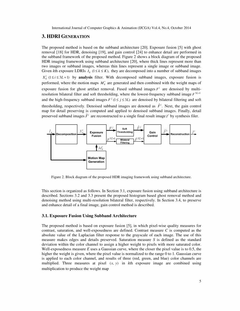
The proposed method is based on the subband architecture [20]. Exposure fusion [5] with ghost
removal [18] for HDR, denoising [19], and gain control [24] to enhance detail are performed in
the subband framework of the proposed method. Figure 2 shows a block diagram of the proposed
HDR imaging framework using subband architecture [20], where thick lines represent more than
two images or subband images, whereas thin lines represent a single image or subband image.
Given kth exposure LDRIs ),1( KkIk ≤≤ they are decomposed into a number of subband images
)131( +≤≤ LiX ik by analysis filter. With decomposed subband images, exposure fusion is
performed, where the motion maps kM ′ are generated and then combined with the weight maps of
exposure fusion for ghost artifact removal. Fused subband images iF are denoised by multi-
resolution bilateral filter and soft thresholding, where the lowest-frequency subband image 13 +LF
and the high-frequency subband images )31( LjF j ≤≤ are denoised by bilateral filtering and soft
thresholding, respectively. Denoised subband images are denoted as .ˆ iF Next, the gain control
map for detail preserving is computed and applied to denoised subband images. Finally, detail
preserved subband images iF~
are reconstructed to a single final result image I ′ by synthesis filer.
Figure 2. Block diagram of the proposed HDR imaging framework using subband architecture.
This section is organized as follows. In Section 3.1, exposure fusion using subband architecture is
described. Sections 3.2 and 3.3 present the proposed histogram based ghost removal method and
denoising method using multi-resolution bilateral filter, respectively. In Section 3.4, to preserve
and enhance detail of a final image, gain control method is described.
3.1. Exposure Fusion Using Subband Architecture
The proposed method is based on exposure fusion [5], in which pixel-wise quality measures for
contrast, saturation, and well-exposedness are defined. Contrast measure C is computed as the
absolute value of the Laplacian filter response to the grayscale of each image. The use of this
measure makes edges and details preserved. Saturation measure S is defined as the standard
deviation within the color channel to assign a higher weight to pixels with more saturated color.
Well-exposedness measure E uses a Gaussian curve, where the closer the pixel value is to 0.5, the
higher the weight is given, where the pixel value is normalized to the range 0 to 1. Gaussian curve
is applied to each color channel, and results of three (red, green, and blue) color channels are
multiplied. Three measures at pixel ),( yx in kth exposure image are combined using
multiplication to produce the weight map
International Journal of Computer Graphics & Animation (IJCGA) Vol.4, No.4, October 2014
6
( ) ( ) ( ) ESC w
k
w
k
w
kk yxEyxSyxCyxW ),(),(),(),( ××= (1)
where the subscript k represents kth exposure image and the influence of three measures of
contrast, structure, and well-exposedness are controlled by power terms wC, wS, and wE,
respectively. For consistent result, the weight map is normalized as
∑ =
=K
kk
kk
yxW
yxWyxW
1),(
),(),(ˆ (2)
where K is the total number of LDRIs used to fuse for generating a single HDRI.
In exposure fusion [5], LDRIs and the weight maps are separately fused using a multi-resolution
technique [29]. Let }{L I denote a Laplacian pyramid of an input LDRI I. Similarly, }ˆ{G W denotes
a Gaussian pyramid of the normalized weight map .W The Laplacian pyramid of the final fused
HDRI is generated as
∑ ==′
K
k
lk
lk
l IWI1
}{L}ˆ{G}{L (3)
where the superscript l ( Ll ≤≤1 ) represents the layer index in a pyramid. A final HDRI I ′ is
obtained by reconstructing .}{L lI ′ Shen et al. [20] applied exposure fusion [5] to subband
architecture using QMF. They built the subband pyramid through an L-level QMF for
decomposing LDRIs and blended the subband images with the weighted maps of exposure fusion
[5]. The blended subband images are modified according to gain control maps [24] to preserve
details of the subband signals. A fused HDRI is reconstructed using detail-preserved subband
images.
The proposed method constructs the subband architecture with Haar wavelet filter and blends
weight maps of exposure fusion in the subband pyramid. Next, the proposed method computes
the gain control map to control the strength of the subband signals and modifies all the subbands
using the gain control map. The modified subband images are reconstructed using the subband
pyramid to a final result image.
For L-level subband pyramid, subband images ),( yxX ik of kth exposure LDRI Ik are generated.
To obtain a fused subband image ,iF the proposed method computes a weighted average of i
kX
at each pixel of subband image as
),(),(~
),(1
yxXyxWyxFik
K
kk
i ∑ == (4)
where kW~
is a Gaussian filtered version of the normalized weight map kW , which prevents
undesirable halo around edge. This weighted averaging function makes a fused image have good
image quality defined by the quality measures. Each subband image contains image features
through image filtering. Thus, the weighted averaging blends image features instead of intensity
using the subband architecture, which is effective for avoiding seams.
International Journal of Computer Graphics & Animation (IJCGA) Vol.4, No.4, October 2014
7
3.2. Histogram Based Ghost Removal
In the proposed method for motion map generation [18], the histogram based multi-level
threshold map [7] is extended to remove the ghost artifact caused by local motion. When contrast
between moving objects and background is small, or the textureless objects move, these motions
give relatively large intensity change than that of variance and local entropy [7]. Thus, the
intensity histogram provides useful methods for local motion detection. The multi-level threshold
map was extended from a median threshold bitmap (MTB), which is a binary bitmap constructed
by partitioning an image using median pixel value of the image as a threshold [6]. The median
threshold is robust to illumination change and thus useful for comparing LDRIs. With this
robustness, the multi-level threshold map [7] was proposed to detect local motion more accurately
than MTB. This method classifies the intensity values into multi-levels and then finds motion
region using the difference between the level indices of intensity values, whereas MTB classifies
pixels into two levels according to intensity value.
The multi-level threshold method [7] detects better local motion than MTB, however, this method
may excessively detect wrong region by dividing the intensity range into more than two levels.
Since its excessive detection finds not only motion region but also region without motion as
motion region, the effect on HDR imaging can be reduced. To avoid this drawback, the method
that adaptively detects motion was introduced [11]. The method separates the LDRI into three
regions: no difference region, small difference region, and large difference region. In the small
difference region, pixels that are connected to the large difference region are selected as motion
region of the large difference. However, the adaptive motion selection has a problem of how to
divide the LDRI into the three regions, because it is difficult to decide which pixels in small
difference region are selected as motion region.
To detect local motion, the proposed motion map [18] is generated based on rank according to the
intensity. It is assumed that the ranks of intensity within an LDRI are similar to those of the other
LDRIs except for the local motion region. Let ),( yxrk )1( kk Rr ≤≤ be rank at pixel (x, y) of kth
exposure image. It can be expressed using a cumulative distribution function of intensity value at
pixel ).,( yx The rank ),( yxrk is normalized to N bit as
kkN
k
kk Rr
R
yxryxr ≤≤
×= 1,2
),(floor),(ˆ (5)
where Rk is the last rank in kth exposure image and )(floor x represents the floor function that
maps a real number to the largest integer smaller than or equal to x. N is selected considering
hardware costs, where larger N gives better performance in a final HDRI, but requires higher
computational cost. It is assumed that the difference of normalized ranks between intensity values
at pixel (x, y) in the reference LDRI and kth exposure image is due to local motion. A reference
image serves as reference for detection of non-static regions. The reference image can be selected
as an image in which area of non-saturated region is the largest among LDRIs, or be produced
using pre-processing such as photometric calibration. However, we assume that in general the
middle-exposure LDRI is well-exposed and saturated region of the image is the least, thus we
select the middle-exposure LDRI as the reference image.
Then, the absolute difference of normalized ranks is computed as
),(ˆ),(ˆ),( yxryxryxd krefk −= (6)
International Journal of Computer Graphics & Animation (IJCGA) Vol.4, No.4, October 2014
8
where the subscript ref represents the middle-exposure. Using dk, the motion maps Mk are defined
as
≠≥
= otherwise ,1
,),(for ,0),(
refkTyxdyxM
rankk
k (7)
where rankT is the threshold value selected to reduce error caused by normalized rank change
between LDRIs due to different exposures or non-ideal intensity change. In the motion maps, the
pixel with zero (0) value represents the pixel with motion.
The motion maps are clustered by applying the morphological operations [30] which are needed
to avoid partial detection of a moving object. First, isolated pixels are removed, and then
disconnected pixels are linked. Finally, the holes that are surrounded by 1-value pixels are filled.
After these morphological operations, the final motion maps are denoted as ).,( yxM k′ The final
rank based motion maps ),( yxM k′ are combined into the weight map in exposure fusion using
multiplication as
( ) ( ) ( ) ).,(),(),(),(),( yxMyxEyxSyxCyxW kw
kw
kw
kkESC ′×××=′ (8)
This weight map ),( yxWk′ is normalized and filtered to produce ),(~
yxWk in (4). Using the
weighted average of ikX by ,
~kW the proposed method generates ghost removed subband images
).,( yxF i
3.3. Noise Removal Using Multi-Resolution Bilateral Filtering
The proposed method removes noise in subband architecture. The subband images decomposed
by the wavelet filter are effectively used for noise removal. In wavelet domain, whereas Tico et
al. [14] only estimated noise variance at every pixel in all LDRIs using the robust median
estimator [31] and then computed weights of each pixel according to the noise variance, the
proposed method estimates and removes the noise in the subband images of a single fused
subband image lF using Zhang and Gunturk’s method [19].
Zhang and Gunturk’s method [19] combines multi-resolution bilateral filtering with wavelet
thresholding for image denoising. This method decomposes an image into low- and high-
frequency subbands as the proposed method. The bilateral filter [32] is an edge-preserving
denoising filter, where the intensity value at each pixel is replaced by Gaussian weighted average
of intensity values of nearby pixels. This filter is applied to the lowest-frequency subband image.
Wavelet thresholding [33] can remove noise components with hard or soft thresholding
operations. Soft thresholding is applied to the high-frequency subband image. Bilateral filter and
wavelet thresholding are also used to provide an effective noise reduction method with visible-
band and wide-band image pair in Yoo et al.’s method [34].
The proposed method applies the bilateral filter to the lowest-frequency subband image 13 +LF
and then obtains bilateral filtered image .ˆ 13 +LF On the other hand, the high-frequency subband
images )31( LjF j ≤≤ are filtered by soft thresholding
International Journal of Computer Graphics & Animation (IJCGA) Vol.4, No.4, October 2014
9
( )( )
−
<=
otherwise,),(),(sgn
),(if,0),(ˆ
softjj
softj
j
TyxFyxF
TyxFyxF (9)
where Tsoft is a threshold in soft thresholding. Soft thresholding suppresses the noise by applying
nonlinear transform to the wavelet coefficients.
3.4. Gain Control Map
After obtaining the fused subband images, the proposed method uses an approach similar to Li et
al.’s method [24] and Shen et al.’s method [20] to compute the gain control map. Generally, a
defect of a denoised image is that detail and texture parts in image are degraded during denoising.
Thus, strong parameter is not used in many denoising algorithms, in which strong denoising filter
is designed though. Therefore, detail enhancement is essential for restoring the artifacts by
denoising. The proposed method preserves the detail and texture parts in subband architecture
without converting other architectures. All processing, i.e., exposure fusion, ghost removal, noise
reduction and detail preservation are performed in a single architecture, where they are closely
related to each other.
When the photoreceptors adapt to the new light level, this process can be modeled as the
logarithm of the input intensity. Thus, the proposed method controls subband signals using the
logarithm of the input intensity, where the high contrast in areas with abruptly changing
illumination is reduced and the details in texture regions are preserved.
To compute the gain control map, an activity map iA )131( +≤≤ Li [24] of ith subband image
from absolute values of local filter response is constructed as
),(ˆ),,(),( yxFyxgyxA ii ∗= σ (10)
where Gaussian filter ),,( σyxg with subband dependent scale parameter σ is used. A gain
control map G is defined using a gamma-like function from the activity map as
)1(
),(),(
−
+=
γ
δ
εi
ii yxA
yxG (11)
where γ is a weighting factor between 0 and 1, and ε prevents singularity in the gain map. This
mapping is a monotonically decreasing function, where if the activity is high, gain is decreased,
otherwise, increased. δ is used as a gain control stability [24].
The gain control maps are aggregated to a single gain control map [24], because each activity in
the subband is correlated with those in adjacent subbands. Thus, an activity map ),( yxAag
aggregated over scales and orientations is computed as
∑+
==
13
1),(),(
L
i
iagyxAyxA (13)
and from which, a single gain control map is derived as
International Journal of Computer Graphics & Animation (IJCGA) Vol.4, No.4, October 2014
10
,),(
),(
)1( −
+=
γ
δ
εyxAyxG
agag (13)
HeightWidth
yxAyx
ag
×=∑ ),(
),(αδ (14)
where Width and Height are width and height of ,F respectively. The single gain control map
),( yxAag is applied to fused subband images ),(ˆ yxF l to get ),(~
yxF i
),(ˆ),(),(~
yxFyxGmyxF iagii ×= (15)
where mi controls the modification extent of different frequency according to scale of the subband
[24]. Finally, the gain controlled subband images iF~
are reconstructed to a single final result
image I ′ by a wavelet synthesis filer.
4. EXPERIMENTAL RESULTS AND DISCUSSIONS
We have tested the proposed method using various sets of real LDRIs with different exposures.
Before simulating the proposed method and other ghost and noise removal methods for HDR,
input images are aligned by a registration method used in [11] to reduce the distortion caused by
global motion.
We compare the performance of the proposed and existing ghost and noise removal methods in
views of subjective quality for HDR imaging, ghost artifact removal, noise removal, and
computation time.
4.1. HDR Imaging
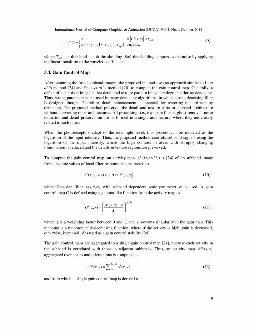
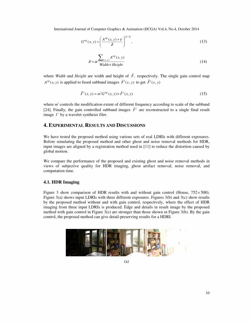
Figure 3 show comparison of HDR results with and without gain control (House, 752× 500).
Figure 3(a) shows input LDRIs with three different exposures. Figures 3(b) and 3(c) show results
by the proposed method without and with gain control, respectively, where the effect of HDR
imaging from three input LDRIs is produced. Edge and details in result image by the proposed
method with gain control in Figure 3(c) are stronger than those shown in Figure 3(b). By the gain
control, the proposed method can give detail-preserving results for a HDRI.
(a)
International Journal of Computer Graphics & Animation (IJCGA) Vol.4, No.4, October 2014
11
(b)
(c)
Figure 3. Comparison of HDR results with and without gain control (752 × 500, House). (a) input LDRIs,
(b) result by the proposed method without gain control, (c) result by the proposed method with gain control.
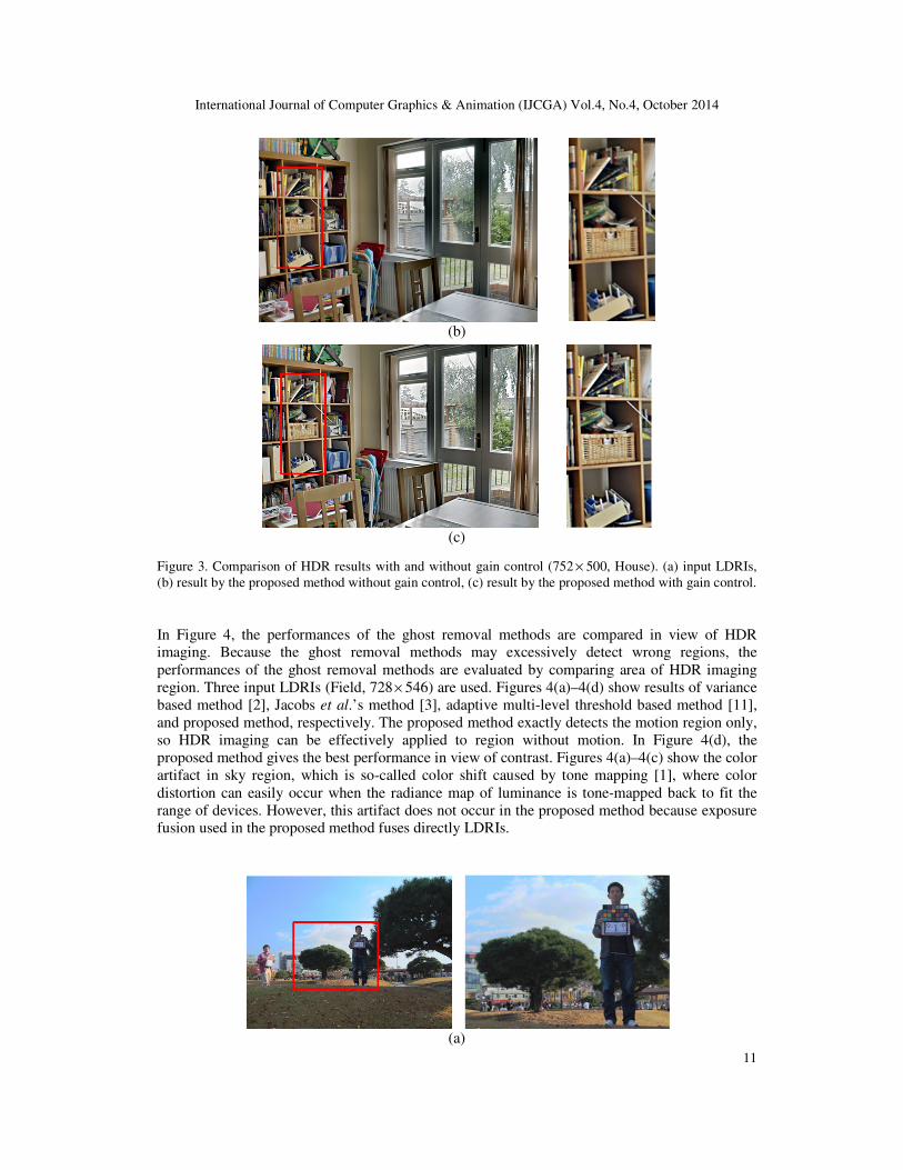
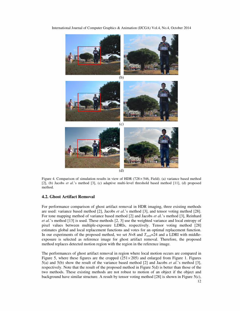
In Figure 4, the performances of the ghost removal methods are compared in view of HDR
imaging. Because the ghost removal methods may excessively detect wrong regions, the
performances of the ghost removal methods are evaluated by comparing area of HDR imaging
region. Three input LDRIs (Field, 728× 546) are used. Figures 4(a)–4(d) show results of variance
based method [2], Jacobs et al.’s method [3], adaptive multi-level threshold based method [11],
and proposed method, respectively. The proposed method exactly detects the motion region only,
so HDR imaging can be effectively applied to region without motion. In Figure 4(d), the
proposed method gives the best performance in view of contrast. Figures 4(a)–4(c) show the color
artifact in sky region, which is so-called color shift caused by tone mapping [1], where color
distortion can easily occur when the radiance map of luminance is tone-mapped back to fit the
range of devices. However, this artifact does not occur in the proposed method because exposure
fusion used in the proposed method fuses directly LDRIs.
(a)
International Journal of Computer Graphics & Animation (IJCGA) Vol.4, No.4, October 2014
12
(b)
(c)
(d)
Figure 4. Comparison of simulation results in view of HDR (728 × 546, Field). (a) variance based method
[2], (b) Jacobs et al.’s method [3], (c) adaptive multi-level threshold based method [11], (d) proposed
method.
4.2. Ghost Artifact Removal
For performance comparison of ghost artifact removal in HDR imaging, three existing methods
are used: variance based method [2], Jacobs et al.’s method [3], and tensor voting method [28].
For tone mapping method of variance based method [2] and Jacobs et al.’s method [3], Reinhard
et al.’s method [13] is used. These methods [2, 3] use the weighted variance and local entropy of
pixel values between multiple-exposure LDRIs, respectively. Tensor voting method [28]
estimates global and local replacement functions and votes for an optimal replacement function.
In our experiments of the proposed method, we set N=8 and Trank=24 and a LDRI with middle-
exposure is selected as reference image for ghost artifact removal. Therefore, the proposed
method replaces detected motion region with the region in the reference image.
The performances of ghost artifact removal in region where local motion occurs are compared in
Figure 5, where these figures are the cropped (251× 205) and enlarged from Figure 1. Figures
5(a) and 5(b) show the result of the variance based method [2] and Jacobs et al.’s method [3],
respectively. Note that the result of the proposed method in Figure 5(d) is better than those of the
two methods. These existing methods are not robust to motion of an object if the object and
background have similar structure. A result by tensor voting method [28] is shown in Figure 5(c),
International Journal of Computer Graphics & Animation (IJCGA) Vol.4, No.4, October 2014
13
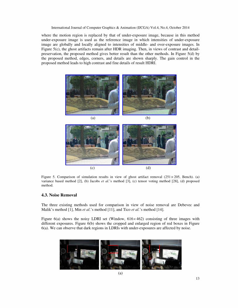
where the motion region is replaced by that of under-exposure image, because in this method
under-exposure image is used as the reference image in which intensities of under-exposure
image are globally and locally aligned to intensities of middle- and over-exposure images. In
Figure 5(c), the ghost artifacts remain after HDR imaging. Then, in views of contrast and detail-
preservation, the proposed method gives better result than the other methods. In Figure 5(d) by
the proposed method, edges, corners, and details are shown sharply. The gain control in the
proposed method leads to high contrast and fine details of result HDRI.
(a) (b)
(c) (d)
Figure 5. Comparison of simulation results in view of ghost artifact removal (251 × 205, Bench). (a)
variance based method [2], (b) Jacobs et al.’s method [3], (c) tensor voting method [28], (d) proposed
method.
4.3. Noise Removal
The three existing methods used for comparison in view of noise removal are Debevec and
Malik’s method [1], Min et al.’s method [11], and Tico et al.’s method [14].
Figure 6(a) shows the noisy LDRI set (Window, 616× 462) consisting of three images with
different exposures. Figure 6(b) shows the cropped and enlarged region of red boxes in Figure
6(a). We can observe that dark regions in LDRIs with under-exposures are affected by noise.
(a)
International Journal of Computer Graphics & Animation (IJCGA) Vol.4, No.4, October 2014
14
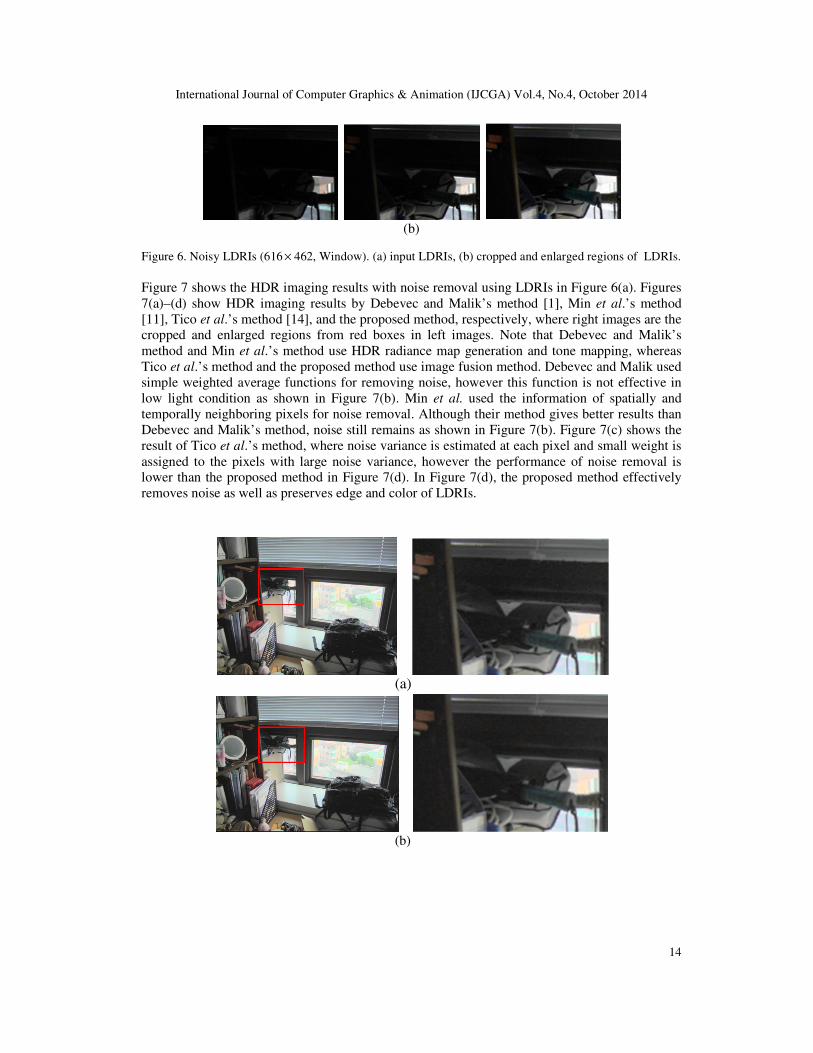
(b)
Figure 6. Noisy LDRIs (616 × 462, Window). (a) input LDRIs, (b) cropped and enlarged regions of LDRIs.
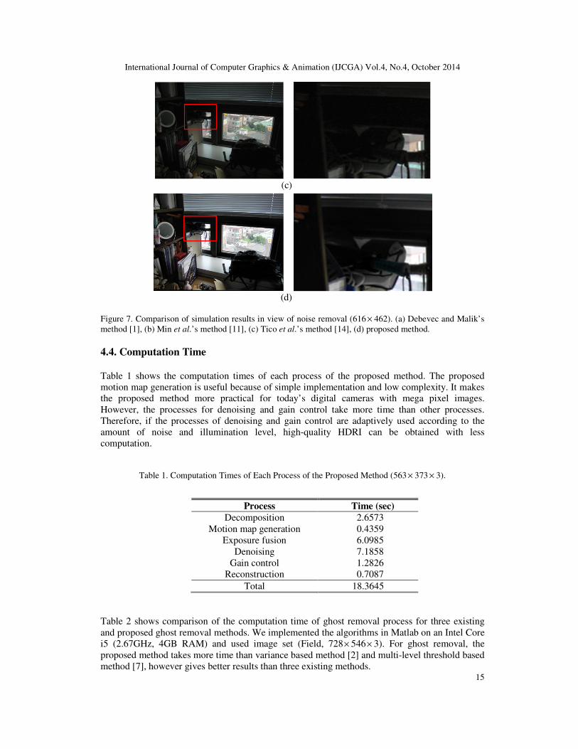
Figure 7 shows the HDR imaging results with noise removal using LDRIs in Figure 6(a). Figures
7(a)–(d) show HDR imaging results by Debevec and Malik’s method [1], Min et al.’s method
[11], Tico et al.’s method [14], and the proposed method, respectively, where right images are the
cropped and enlarged regions from red boxes in left images. Note that Debevec and Malik’s
method and Min et al.’s method use HDR radiance map generation and tone mapping, whereas
Tico et al.’s method and the proposed method use image fusion method. Debevec and Malik used
simple weighted average functions for removing noise, however this function is not effective in
low light condition as shown in Figure 7(b). Min et al. used the information of spatially and
temporally neighboring pixels for noise removal. Although their method gives better results than
Debevec and Malik’s method, noise still remains as shown in Figure 7(b). Figure 7(c) shows the
result of Tico et al.’s method, where noise variance is estimated at each pixel and small weight is
assigned to the pixels with large noise variance, however the performance of noise removal is
lower than the proposed method in Figure 7(d). In Figure 7(d), the proposed method effectively
removes noise as well as preserves edge and color of LDRIs.
(a)
(b)
International Journal of Computer Graphics & Animation (IJCGA) Vol.4, No.4, October 2014
15
(c)
(d)
Figure 7. Comparison of simulation results in view of noise removal (616 × 462). (a) Debevec and Malik’s
method [1], (b) Min et al.’s method [11], (c) Tico et al.’s method [14], (d) proposed method.
4.4. Computation Time
Table 1 shows the computation times of each process of the proposed method. The proposed
motion map generation is useful because of simple implementation and low complexity. It makes
the proposed method more practical for today’s digital cameras with mega pixel images.
However, the processes for denoising and gain control take more time than other processes.
Therefore, if the processes of denoising and gain control are adaptively used according to the
amount of noise and illumination level, high-quality HDRI can be obtained with less
computation.
Table 1. Computation Times of Each Process of the Proposed Method (563 × 373 × 3).
Table 2 shows comparison of the computation time of ghost removal process for three existing
and proposed ghost removal methods. We implemented the algorithms in Matlab on an Intel Core
i5 (2.67GHz, 4GB RAM) and used image set (Field, 728× 546× 3). For ghost removal, the
proposed method takes more time than variance based method [2] and multi-level threshold based
method [7], however gives better results than three existing methods.
Process Time (sec)
Decomposition 2.6573 Motion map generation 0.4359
Exposure fusion 6.0985 Denoising 7.1858
Gain control 1.2826 Reconstruction 0.7087
Total 18.3645
International Journal of Computer Graphics & Animation (IJCGA) Vol.4, No.4, October 2014
16
Table 2. Comparison of the Computation Time of Ghost Removal Process (728 × 546 × 3, Field).
5. CONCLUSIONS
We propose a ghost and noise removal method in exposure fusion using subband architecture.
Exposure fusion is constructed in the subband architecture and the proposed histogram based
motion maps are used for ghost artifact removal caused by local motion, where the motion maps
are combined with the weight maps of exposure fusion. Fused subband images are denoised by
multi-resolution bilateral filtering and soft threshlolding, and then details of the subband images
are enhanced through the gain control. Finally, detail-preserved subband images are reconstructed
to a single HDRI. Experimental results show that the proposed method is effective to detect only
motion region and to remove noise, while giving good results for HDR imaging. Future research
will focus on more practical implementation of the proposed method. In real captured LDRI sets,
over-exposure LDRI is affected by blur. Thus, future research will focus on reducing the effect of
blur image degradation in generating a single high-quality HDRI.
ACKNOWLEDGEMENTS
This work was supported in part by Digital Imaging Business, Samsung Electronics, Co. Ltd.
REFERENCES
[1] P. Debevec and J. Malik, “Recovering high dynamic range radiance maps from photographs”, Proc.
SIGGRAPH, Los Angeles, CA, Aug. 1997, pp. 369–378.
[2] E. Reinhard, G. Ward, P. Debevec, and S. Pattanaik, High Dynamic Range Imaging: Acquisition,
Display, and Image Based Lighting, Morgan Kaufmann, San Francisco, CA, 2006.
[3] K. Jacobs, C. Loscos, and G. Ward, “Automatic high dynamic range image generation for dynamic
scenes”, IEEE Computer Graphics and Applications, Vol. 28, No. 2, Mar. 2008, pp. 84–93.
[4] A. A. Goshtasby, “Fusion of multi-exposure images”, Image and Vision Computing, Vol. 23, No. 6,
June 2005, pp. 611−618.
[5] T. Martens, J. Kautz, and F. V. Reeth, “Exposure fusion: A simple and practical alternative to high
dynamic range photography”, Computer Graphics Forum, Vol. 28, No. 1, Mar. 2009, pp. 161–171.
[6] G. Ward, “Fast, robust image registration for compositing high dynamic range photographs for
handheld exposures”, Journal of Graphics Tools, Vol. 8, No. 2, Jan. 2003, pp. 17–30.
[7] T.-H. Min, R.-H. Park, and S. Chang, “Histogram based ghost removal in high dynamic range images”,
Proc. IEEE Int. Conf. Multimedia and Expo, New York, June/July 2009, pp. 530−533.
[8] W. Zhang and W.-K. Cham, “Gradient-directed composition of multi-exposure images,” Proc. IEEE
Conf. Computer Vision and Pattern Recognition, San Francisco, CA, June 2010, pp. 530−536.
[9] S. B. Kang, M. Uyttendaele, S. Winder, and R. Szeliski, “High dynamic range video”, ACM Trans.
Graphics, Vol. 22, No. 3, July 2003, pp. 319–325.
[10] A. O. Akyuz and E. Reinhard, “Noise reduction in high dynamic range imaging”, Journal of Visual
Communication and Image Representation, Vol. 18, No. 5, Oct. 2007, pp. 366–376.
Method Time (sec)
Variance based method [2] 0.7594 Jacobs et al.’s method [3] 3.2651
Multi-level threshold based method [7] 0.8257 Proposed method 1.5170
International Journal of Computer Graphics & Animation (IJCGA) Vol.4, No.4, October 2014
17
[11] T.-H. Min, R.-H. Park, and S. Chang, “Noise reduction in high dynamic range images”, Signal, Image,
and Video Processing, Vol. 5, No. 3, Sept. 2011, pp. 315–328.
[12] A. A. Bell, C. Seiler, J. N. Kaftan, and T. Aach, “Noise in high dynamic range imaging”, Proc. Int.
Conf. Image Processing, San Diego, CA, Oct. 2008, pp. 561–564.
[13] E. Reinhard, M. Stark, P. Shirley, and J. Ferwerda, “Photographic tone reproduction for digital
images”, ACM Trans. Graphics, Vol. 21, No. 3, July 2002, pp. 267–273.
[14] M. Tico, N. Gelfand, and K. Pulli, “Motion-blur-free exposure fusion”, in Proc. Int. Conf. Image
Processing, Hong Kong, China, Sept. 2010, pp. 3321–3324.
[15] S. Raman and S. Chaudhuri, “Bilateral filter based compositing for variable exposure photography”,
Proc. Eurographics Conf., Munich, Germany, Mar. 2009, pp. 1–4.
[16] B.-D. Choi, S.-W. Jung, and S.-J. Ko, “Motion-blur-free camera system splitting exposure time”,
IEEE Trans. Consumer Electronics, Vol. 54, No. 3, Aug. 2008, pp. 981−986.
[17] J. Jia, J. Sun, C.-K. Tang, and H.-Y. Shum, “Bayesian correction of image intensity with spatial
consideration”, Proc. 8th European Conf. Computer Vision, Lecture Notes in Computer Science, Vol.
3023, Prague, Czech Republic, May 2004, pp. 342−354.
[18] D.-K. Lee, R.-H. Park, and S. Chang, “Improved histogram based ghost removal in exposure fusion
for dynamic range images”, Proc. 15th IEEE Int. Symp. Consumer Electronics, Singapore, June 2011,
pp. 586–591.
[19] M. Zhang and B. Gunturk, “Multiresolution bilateral filtering for image denoising”, IEEE Trans.
Image Processing, Vol. 17, No. 12, Dec. 2008, pp. 2324–2333.
[20] J. Shen, Y. Zhao, and Y. He, “Detail-preserving exposure fusion using subband architecture”, The
Visual Computer, Vol. 28, No. 5, May 2012, pp. 463–473.
[21] S. Lee, “Compressed image reproduction based on block decomposition”, IET Image Processing, Vol.
3, No. 4, Aug. 2009, pp. 188–199.
[22] X. Li, F. Li, L. Zhuo, and D. D. Feng, “Layers-based exposure fusion algorithm”, IET Image
Processing, Vol. 7, No. 7, Oct. 2013, pp. 701–711.
[23] M. Bertalmio and S. Levine, “Variational Approach for the Fusion of Exposure Bracketed Pairs”,
IEEE Trans. Image Processing, Vol. 22, No. 2, Feb. 2013, pp. 712–723.
[24] Y. Li, L. Sharan, and E. H. Adelson, “Compressing and companding high dynamic range images with
subband architectures”, ACM Trans. Graphics, Vol. 24, No. 3, July 2005, pp. 836–844.
[25] S. Baker and I. Matthews, “Lucas-Kanade 20 years on: A unifying framework”, Int. Journal of
Computer Vision, Vol. 56, No. 3, Feb. 2004, pp. 221–255.
[26] Y. Keller and A. Averbuch, “Fast gradient methods based on global motion estimation for video
compression”, IEEE Trans. Circuits Syst. Video Technol., Vol. 13, No. 4, Apr. 2003, pp. 300−309.
[27] E. A. Khan, A. O. Akyuz, and E. Reinhard, “Robust generation of high dynamic range images”, Proc.
Int. Conf. Image Processing, Atlanta, GA, Oct. 2006, pp. 2005–2008.
[28] J. Jia and C. K. Tang, “Tensor voting for image correction by global and local intensity alignment”,
IEEE Trans. Pattern Analysis and Machine Intelligence, Vol. 27, No. 1, Jan. 2005, pp. 36–50.
[29] P. J. Burt and E. H. Adelson, “The Laplacian pyramid as a compact image code”, IEEE Trans.
Communications, Vol. 31, No. 4, Apr. 1983, pp. 532–540.
[30] R. C. Gonzalez and R. E. Woods, Digital Image Processing. 3rd ed., Upper Saddle River, NJ: Pearson
Education Inc., 2010.
[31] D. Donoho and I. Johnstone, “Ideal spatial adaptation by wavelet shrinkage”, Biometrika, Vol. 81, No.
3, Aug. 1994, pp. 425–455.
[32] C. Tomasi and R. Manduchi, “Bilateral filtering for gray and color images”, Proc. Int. Conf. Computer
Vision, Bombay, India, Jan. 1998, pp. 839–846.
[33] S. G. Chang, B. Yu, and M. Vetterli, “Adaptive wavelet thresholding for image denoising and
compression”, IEEE Trans. Image Processing, Vol. 9, No. 9, Sept. 2000, pp. 1532–1546.
[34] Y. Yoo, W. Choe, J. Kwon, S. Park, S. Lee, and C.-Y. Kim, “Low-light imaging method with visible-
band and wide band image pair”, Proc. Int. Conf. Image Processing, Cairo, Egypt, Nov. 2009, pp.
2273–2276.
International Journal of Computer Graphics & Animation (IJCGA) Vol.4, No.4, October 2014
18
Authors
Dong-Kyu Lee received the B.S. and M.S. degrees in electronic engineering from Sogang University in
2010 and 2012, respectively. His current research interests are image processing and image enhancement.
Rae-Hong Park received the B.S. and M.S. degrees in electronics engineering from Seoul National
University, Seoul, Korea, in 1976 and 1979, respectively, and the M.S. and Ph.D. degrees in electrical
engineering from Stanford University, Stanford, CA, in 1981 and 1984, respectively. In 1984, he joined the
faculty of the Department of Electronic Engineering, School of Engineering, Sogang University, Seoul,
Korea, where he is currently a Professor. In 1990, he spent his sabbatical year as a Visiting Associate
Professor with the Computer Vision Laboratory, Center for Automation Research, University of Maryland
at College Park. In 2001 and 2004, he spent sabbatical semesters at Digital Media Research and
Development Center (DTV image/video enhancement), Samsung Electronics Co., Ltd., Suwon, Korea. In
2012, he spent a sabbatical year in Digital Imaging Business (R&D Team) and Visual Display Business
(R&D Office), Samsung Electronics Co., Ltd., Suwon, Korea. His current research interests are video
communication, computer vision, and pattern recognition. He served as Editor for the Korea Institute of
Telematics and Electronics (KITE) Journal of Electronics Engineering from 1995 to 1996. Dr. Park was
the recipient of a 1990 Post-Doctoral Fellowship presented by the Korea Science and Engineering
Foundation (KOSEF), the 1987 Academic Award presented by the KITE, the 2000 Haedong Paper Award
presented by the Institute of Electronics Engineers of Korea (IEEK), the 1997 First Sogang Academic
Award, and the 1999 Professor Achievement Excellence Award presented by Sogang University. He is a
co-recipient of the Best Student Paper Award of the IEEE Int. Symp. Multimedia (ISM 2006) and IEEE Int.
Symp. Consumer Electronics (ISCE 2011).
SoonKeun Chang received his B.S. degree in astronomy and space science from KyungHee University,
Korea, in 2000 and M.S. degree in control engineering from Kanazawa University in 2003. He received a
Ph.D. degree in control engineering from Tokyo Institute of Technology (TITech) in 2007. Now he works
at Samsung Electronics Co., Ltd., Korea. His main research interests include computer vision and image
processing.