
GFW adv - gefkor.com
53
1 80962_MHW_GFW_12-2011_ENG INDEX Indicates contents of sections, general instructions, notes, and other points to which the reader’s attention needs to be called. Indicates a particularly delicate situation that could affect the safety or correct operation of the controller, or an instruction that MUST be followed to prevent hazards. Indicates a risk to the user’s safety due to high voltage at the points indicated. Indicates a suggestion based on the experience of GEFRAN’s Technical Personnel that could be especially useful under certain circumstances. Indicates a reference to Detailed Technical Documents available on the GEFRAN website www.gefran.com. GRAPHIC SYMBOLS To differentiate the type and importance of the information in this User Manual, graphic reference symbols are used to make such information easier to interpret. 1 Preliminary instructions 2 1.1 Profile 1.2 General description 1.3 Preliminary instructions 2 Installation and Connection 4 2.1 Electrical power supply 2.2 Notes on electrical safety and electromagnetic compatibility 2.3 Recommendations for correct installation for purposes of EMC 2.4 Dimensions 2.5 Template dimensions 2.6 Installation 2.7 General description GFW 2.8 Cleaning/checking or replacing the fan 2.9 Replacing internal fuse (Optional) 2.10 Card insertion for fieldbus interface 2.11 Connection of expansion modules 3 Electrical connections 12 3.1 Power connections 3.2 Functions of LED indicators 3.3 Description Input/Output 3.4 Connector J1 outputs 5...10 3.5 Connector J2 power supply 3.6 Connector J2 digital input 3.7 Connector J3 auxiliary inputs 2...5 3.8 Connector J4 inputs 1...4 3.9 Connector J6: inputs PID 3.10 Description of dip-switches 3.11 Serial communication ports 3.12 Connection example: Power section 4 Installation of serial network 40 4.1 “AUTOBAUD SERIAL 1” sequence 4.2 “AUTONODE PORT 1” sequence 5 Technical Characteristics 42 5.1 Derating Curves Gfw (scr) 5.2 Derating Curves Gfw with electronic fuse (IGBT) 6 Technical-Commercial information 47 6.1 Order code 6.2 Accessories 6.3 Fuses / Fuseholders GFW adv ADVANCED MODULAR POWER CONTROLLER INSTALLATION AND OPERATION MANUAL Versione software: 1.0x code 80962 - 12/2011 - ENG
Transcript of GFW adv - gefkor.com

180962_MHW_GFW_12-2011_ENG
INDEX
Indicates contents of sections, general instructions, notes, and other points to which the reader’s attention needs to be called.
Indicates a particularly delicate situation that could affect the safety or correct operation of the controller, or an instruction that MUST be followed to prevent hazards.
Indicates a risk to the user’s safety due to high voltage at the points indicated.
Indicates a suggestion based on the experience of GEFRAN’s Technical Personnel that could be especially useful under certain circumstances.
Indicates a reference to Detailed Technical Documents available on the GEFRAN website www.gefran.com.
GRAPHIC SYMBOLSTo differentiate the type and importance of the information in this User Manual, graphic reference symbols are used to make such information easier to interpret.
1 Preliminary instructions 2 1.1 Profile 1.2 General description 1.3 Preliminary instructions
2 Installation and Connection 4 2.1 Electrical power supply 2.2 Notes on electrical safety and electromagnetic compatibility 2.3 Recommendations for correct installation for purposes of EMC 2.4 Dimensions 2.5 Template dimensions 2.6 Installation 2.7 General description GFw 2.8 Cleaning/checking or replacing the fan 2.9 Replacing internal fuse (Optional) 2.10 Card insertion for fieldbus interface 2.11 Connection of expansion modules
3 Electrical connections 12 3.1 Power connections 3.2 Functions of LED indicators 3.3 Description Input/Output
3.4 Connector J1 outputs 5...10 3.5 Connector J2 power supply 3.6 Connector J2 digital input 3.7 Connector J3 auxiliary inputs 2...5 3.8 Connector J4 inputs 1...4 3.9 Connector J6: inputs PID 3.10 Description of dip-switches 3.11 Serial communication ports 3.12 Connection example: Power section
4 Installation of serial network 40 4.1 “AUTOBAUD SERIAL 1” sequence 4.2 “AUTONODE PORT 1” sequence
5 Technical Characteristics 42 5.1 Derating Curves Gfw (scr) 5.2 Derating Curves Gfw with electronic fuse (IGBT)
6 Technical-Commercial information 47 6.1 Order code 6.2 Accessories 6.3 Fuses / Fuseholders
GFW advADVANCED MODULAR POWER CONTROLLER
INSTALLATION ANDOPERATION MANUAL
Versione software: 1.0x
code 80962 - 12/2011 - ENG

2 80962_MHW_GFW_12-2011_ENG
1 • PRELIMINARY INSTRUCTIONS
1.1 Profile
The “ GFw adv” series of microprocessor advanced solid state power units controls high electric powers with different types of heating elements, single-phase, biphase or triphase.Current levels range from 40A to 250A, nominal voltage from 480 VAC to 600VAC.The command input is configurable and accepts 0-10V, 0/4-20mA signals, potentiometer, logic signals, including with PwM modes for cost effective solutions.The device can also be operated via Modbus RTU serial communication, with IN/OUT chain connections facilitated by plug-in RJ10 (telephone) connectors.The several trigger modes are software configurable and provide:- ZC: Zero Crossing constant cycle time (settable in range 1-200sec), for conventional loads- BF: Burst-Firing, Zero crossing with optimized minimum cycle time, for systems with low thermal inertia, medium-wave IR lamps- HSC: Half Single Cycle Zero Crossing corresponds to Burst Firing that manages single semi-cycles of conduction or stop cycles, useful for short-wave IR lamps, reduces flickering and limits generation of EMC noise on the power line (applied only to single-phase load or open delta).- PA: Phase angle control, useful for short-wave IR lamps, transformer primaries. Completely eliminates flickering of load filaments, but generates EMC noise on power line (harmonics).Soft Start ramp functions can be assigned to these controls, with options such as “current limit” that keeps current peaks at power-on and RMS current level at full power under control.Thanks to sophisticated Hardware and Software solutions, you can precisely control different types of loads.Phase angle control (the only control method that completely eliminates IR lamp flickering), matched with current, voltage, or load power feedback functions, let you confidently use “critical” applications such as (for example), special resistors such as special Super Khantal™ heating elements, Silicon Carbide resistors, or transformer primaries either single-phase or triphase.GFw runs complete diagnostics of current, voltage, power, and temperature levels:
Current Diagnostics:- Total and partial load interrupt alarm- Self-learn function of alarm limit for interrupted load- Alarm for SCR in short circuit- Alarm for load in short circuit or overcurrent - Alarm for interrupted internal fuse
Voltage Diagnostics:- Alarm for absence of phase - Signal for incorrect rotation of 3 phases (for triphase applications)- Alarm for triphase line unbalance
Temperature Diagnostics:- Measurement of power module temperature- Alarm for over temperature of power module- Measurement of power terminals temperature- Alarm for over temperature of power terminals- Alarm for absence of 24V supply to cooling fan
Power control with Soft start ramp limits load, optimizes the consumptions and increases the load operating duration.The internal resettable “electronic fuse” is an exclusive option: it lets you avoid extra-rapid fuses and greatly reduces machine downtimes and cost caused by looking for and replacing such fuses.Parameters can be configured from an optional keypad with LCD screen that attaches magnetically to the front panel and from PC with the GF_eXpress configuration kit, which lets you save all parameters in a configuration file that is easy to manage and to copy to other devices..GFw always provides an RS485 serial connection (PORT1) with Modbus RTU protocol to control currents, voltages, powers, load status, and device status from the supervisor terminal (HMI) or PLC.A second (optional) communication port is offered that lets you choose from among the following Fieldbuses: Modbus RTU, Profibus DP, CanOpen, Devicenet, Modbus-TCP, Ethernet IP, EtherCAT .
The section contains general information and warnings to be read before installing, configuring and using the controller.
1.2 General DescriPtion
GFw is single-zone advanced solid state power unit, extremely compact, equipped with different optional functions; it offers an exclusive combination of performance, reliability, and flexibility. In particular, this new line of Gefran solid state relays is the ideal solution for sectors demanding high performance and continuity of service, such as: •Thermoforming•Blowing•Hotrunnersforinjectionpresses•Texturizingoffibers•Heattreatmentfurnaces•Woodworkingmachines•Glasstemperingfurnaces
The modules Series GFw are based on an extremely versatile hardware and software platform, with options to select the best I/O configuration for your system.
GFw is used for the power control of single-phase, Dual-Phase and 3-phase loads, including resistive loads with high and low temperature coefficient, short wave IR lamps, or transformer primaries.
Attention: the description of programming andconfiguration parameters are contained in the “Programming and configuration” manual,downloadable from the website www.gefran.com

380962_MHW_GFW_12-2011_ENG
1.2 Preliminary instruction
Read the following preliminary instructions beforeinstalling and using the GFX4-IR modular powercontroller. Thiswillmakestart-upfasterandavoidsomeproblemsthatcouldbemistakenlyinterpretedas malfunctions or limitations of the controller.
Immediately after unpacking the unit, check the order code and the other data on the label attached to the outside of the container. write them on the following table. This data must always be available and given to Gefran Customer Care representatives if technical service is needed.
Check that the controller is in perfect condition, was not damaged during shipment, and that the package also contains the CD that contains other useful information such as the “Configuration and Programming” manual, memory map etc...
Immediately report any errors, shortages, or signs of damage to your Gefran dealer. Check that the order code matches the configuration requested for the intended application by consulting the section: “Technical-Commercial Information.”
Example: GFw 150 - 480 - 0 - 1 - R - ... Model Nominal current Nominal voltage PID inputs absent Contol option: Current limit Output sAux. 4 Relay... ecc. ...
See paragraph ... “ Dimensions and mounting” before installing the GFw on the machine/host system control panel.
To configure the PC use the Sw Gefran GF-Express kit and the relative connection cable.For the order code, see Section “Technical-Commercial Information”.
Users and/or system integrators who want detailed information on serial communication between Gefran standard and/or industrial PCs and Gefran Programmable Instruments can access Technical Reference Documents on serial communication and MODBus protocol, etc., in Adobe Acrobat format on the Gefran website www.gefran.com:•SerialCommunication•MODBusProtocol•FIELDBUSprotocols(Various)
Before calling Gefran Customer Care in case of assumed malfunctions, please see the Troubleshooting Guide in the “Maintenance” section and, if necessary, the F.A.Q. (Frequently Asked Questions) section on the Gefran websitewww.gefran.com
SN ............................... (Serial Number)CODE ......................... (Product code)TYPE........................... (Order code)SUPPLY...................... (Type of electrical power supply)VERS. ......................... (Firmware Version)

4 80962_MHW_GFW_12-2011_ENG
This section contains the instructions needed for correct installation of GFW modular power controller on the machine/host system control panel and for correct connection of the power supply, inputs, outputs and interfaces.
CAREFULLY READ THE FOLLOWING WARNINGS BEFORE INSTALLING THE INSTRUMENT!Disregard of such warnings could create electrical safety and electromagnetic compatibility problems, as well as void the warranty.
2.1 Electrical Power suPPly
• thecontrollerDOESNOThaveanOn/Offswitch:theuser must install switch/isolator conforming to safety requisites (CE mark) to cut off the power supply up-line of the controller. The switch must be installed in the immediate vicinity of the controller in easy reach of the operator. A single switch can be used for multiple devices.
* the earth connection must be made with a specific lead
• if the product is used in applications with risk of harm to persons or damage to machines or materials, it MUST be equipped with auxiliary alarm devices. It is advisable to provide the ability to check for tripped alarms during regular operation. DO NOT install the product in rooms with hazardous (inflammable or explosive) atmosphere; it may be connected to elements that operated in such atmosphere only by means of appropriate interfaces that conform to current safety standards.
2.2 Notes on electrical safety anD electromagnetic comPatibility:
2.2.1 MARCATURA CE: EMC (electromagnetic compatibility) conformity in compliance with Directive 89/336/CEE and following modifications. Series GFw are mainly intended for industrial use, installed on panels or control panels of production process machines or systems. For purposes of electromagnetic compatibility, the most restrictive generic standards have been adopted, as shown on the table.
2.2.2 LV (low voltage) conformity in compliance with Directive 2006/95/CE.
EMC conformity has been verified with the connections indicated on table 1.
2.3 RecommenDations for correct installation for PurPoses of EMC2.3.1 Instrument power supply• Thepowersupplyfortheelectronicinstrumentationonthe panels must always come directly from a cut-off device with fuse for the instrument part. • Electronicinstrumentationandelectromechanicalpower devices such as relays, contactors, solenoids, etc., MUST ALwAYS be powered by separate lines.• Whenthepowersupplylineofelectronicinstrumentsis heavily disturbed by switching of thyristor power groups or by motors, you should use an isolation transformer only for the controllers, grounding its sheathing. • Itisimportantforthesystemtobewell-grounded: - voltage between neutral and ground must not be > 1V -Ohmicresistancemustbe<6Ω;• Ifthegridvoltageishighlyunstable,useavoltagestabilizer.• Inproximityofhigh-frequencygeneratorsorarcwelders, use adequate grid filters.• Thepowersupplylinesmustbeseparatefrominstrument input and output lines.• SupplyfromClassIIorfromlimitedenergysource
2.3.2 Input and output connections Before connecting or disconnecting any connection, always check that the power and control cables are isolated from voltage Appropriate devices must be provided: fuses or
automatic switches to protect power lines. The fuses present in the module function solely as a protection for the GFw semiconductors.• Connectedoutsidecircuitsmustbedoublyisolated.• Toconnectanaloginputs,straingauges,linears,(TC,RTD), you have to: - physically separate the input cables from those of the power supply, outputs, and power connections. - use braided and shielded cables, with sheathing grounded at a single point.
2.3.3 Installation notesUse the extra-rapid fuse indicated in the catalogue according to the connection example equipped. - Moreover, the applications with solid-state units require a safety automatic switch to section the load power line.To ensure the high reliability of the device, it is necessary to install it properly inside the panel so to obtain an adequate thermal exchange. Fit the device vertically (maximum angle 10° to the vertical axis) see figure 3•Verticaldistancebetweenadeviceandthepanelwall>100mm•Horizontaldistancebetweenadeviceandthepanelwallatlast 10mm•Verticaldistancebetweenadeviceandthenextoneatlast300mm.•Horizontaldistancebetweenadeviceandthenextoneatlast10mm.Check that the cable holder runners do not reduce these distances, in this case fit the cantilever units opposite the panel so that the air can flow vertically without any obstacles. •dissipationofdevicethermalpowerwitheffectsoninstallationroom temperature.
2 • INSTALLATION AND CONNECTION

580962_MHW_GFW_12-2011_ENG
•thermalpowerdissipationwithlimitsoninstallationroomtemperature.•requiresexchangewithexternalairoranairconditionertotransfer dissipated power outside the panel.•maximumlimitsofvoltageandderivedpoweroftransientsonthe line, for which the solid state power unit contains protective devices (based on the model).•presenceofdispersioncurrentinGFWinnon-conductingstate (current of a few mA due to RC Snubber circuit to protect the thyristor).
GEFRAN S.p.A. assumes no liability for any damage to persons or property deriving from tampering, from incorrect or improper use, or from any use not conforming to the characteristics of the controller and to the instructions in this User Manual.
AC semiconductor motor controllers and conductors for non-motor loadsEmission enclosurecompliant in firing mode single cycle and phase angle if external filter fitted
EN 60947-4-3
EN 60947-4-3CISPR-11EN 55011
Class A Group 2
Table 1 EMC Emission
Table 2 EMC Immunity
Table 3 LVD safetySafety requirements for electrical equipment for measurement, control and laboratory use
EN 61010-1
ATTENTIONThis product has been designed for class A equipment. Use of the product in domestic environments may cause radio interference, in which case the user may be required to employ additional mitigation methods.
Generic standards, immunity standard for industrial environmentsESD immunity
RF interference immunity
Conducted disturbance immunity
Burst immunity
Surge immunity
Magnetic fields immunity
Voltage dips, short interruptions and voltage immunity tests
EN 60947-4-3
EN 61000-4-2
EN 61000-4-3 /A1
EN 61000-4-6
EN 61000-4-4
EN 61000-4-4/5
Test are not required. Immunity is demonstrated by the successful completion of the operating capability testEN 61000-4-11
4 kV contact discharge8 kV air discharge
10 V/m amplitude modulated 80 MHz-1 GHz10 V/m amplitude modulated 1.4 GHz-2 GHz10 V/m amplitude modulated 0.15 MHz-80 MHz2 kV power line2 kV I/O signal linePower line-line 1 kV Power line-earth 2 kVSignal line-earth 2 kVSignal line-line 1 kV
100%U, 70%U, 40%U,
EMC filters are required in PA mode (Phase Angle, i.e., SCR trigger with phase angle modulation). The filter model and current level depend on the configuration and load used. The power filter MUST by connected as close as possible to the GFw. You can use a filter connected between the power line and GFw or an LC group connected between the GFw output and the load

6 80962_MHW_GFW_12-2011_ENG
INSULATION DIAGRAM
POW
ER S
UPP
LY
18...
32Vd
c
LED
s
OU
TPU
TSC
PUIN
PUTS
POW
ER C
ON
TRO
L
Mai
n Pr
oces
sor
EEpr
om
RAM
OU
T1,2
,3LO
GIC
OU
T5,6
,7,8
CO
NTI
NU
OU
SLO
GIC
OU
T5,6
,7,8
TRIA
C, R
ELAY
Con
nect
ed to
±5V
CPU
Con
nect
ed to
18...
32Vd
c
Con
nect
ed to
5V (P
OR
T 1)
Con
nect
ed to
90...
600V
Lege
nd
1KV
1KV
2KV
1KV
DC
/ D
C±5
V
1KV
DC
/ D
C5V
OU
T1,2
,3LO
GIC
4KV
max
600
Vac
SSR
SSR
1, S
SR2,
SSR
3
max
230
Vac
POR
T 2
POR
T 1
MO
DBu
s R
S485 50
0V1K
V
Fiel
dBus
Ethe
rnet
Mod
bus
TCP
Ethe
rCAT
C
anO
pen
Dev
iceN
etPr
ofib
us D
P
MO
DBu
s R
S485
ANAL
OG
CO
MM
AND
INPU
T
PID
INPU
T (I
N1)
AUXI
LIAR
Y IN
PUT
IN2,
IN3,
IN4,
IN5
TA IN
PUT
(I_lo
ad)
TA1,
TA2
, TA3
TA IN
PUT
(I_lin
e)TV
1, T
V2, T
V3
DIG
ITAL
INPU
TD
I1, D
I2, D
I31K
V

780962_MHW_GFW_12-2011_ENG
2.4 Dimensions
GFW MASTER
Figure 1
Lateral view with keypad
Lateral view without keypad
GFW DUAL-PHASE(Master + 1 Expansion)
GFW THREE-PHASE(Master + 2 Expansions)

8 80962_MHW_GFW_12-2011_ENG
2.6 installation
2.5 temPlate Dimensions
Fastening may be done with (5MA). All dimensions are expressed in mm.
Attention: respect the minimum distances shown in figure 3 to provide adequate air circulation.
GFw MASTER GFw DUAL-PHASE GFw THREE-PHASE
PANEL MOUNTINGAND CUT-OUT DIMENSIONS
Figure 2
Figure 3
980962_MHW_GFW_12-2011_ENG
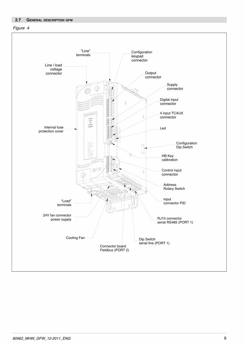
2.7 general DescriPtion gfw
“Line”terminals
Configurationkeypad connector
Line / load voltage
connector Outputconnector
Supplyconnector
Digital inputconnector
4 input TCAUX connector
Led
ConfigurationDip Switch
HB Keycalibration
Control input connector
input connector PID
RJ10 connectorserial RS485 (PORT 1)
Dip Switchserial line (PORT 1)
Connector boardFieldbus (PORT 2)
24V fan connector power supply
“Load”terminals
Cooling Fan
AddressRotary Switch
Internal fuse protection cover
Figure 4

10 80962_MHW_GFW_12-2011_ENG
Figure 5
2.8 cleaning/checking or rePlacing the fan
PERIODIC CLEANINGEvery 6-12 months (depending on the dust level of the installation) blow a compressed air jet downward through the upper rectangular cooling grilles (on the side opposite the fan).This will clean the internal heat dissipater and the cooling fan.
IN CASE OF OVERHEAT ALARM If periodic cleaning does not eliminate the problem, do as follows:a Remove the fan support grille by detaching the two support tabsb Disconnect the fan connector from the boardc Check the condition of the fan d Clean or replace the fan Attention: check that the arrow (on the fan) indicating the direction of air flow is pointing to the heat sink e Insert the connector into the board f Insert the fan support grille until it attachesg Power up the device and check fan rotation when at least one load is on
1. Fan2. Lower grille (ventilation intake) 3. Detail of insertion of fan connector in PCB
1180962_MHW_GFW_12-2011_ENG
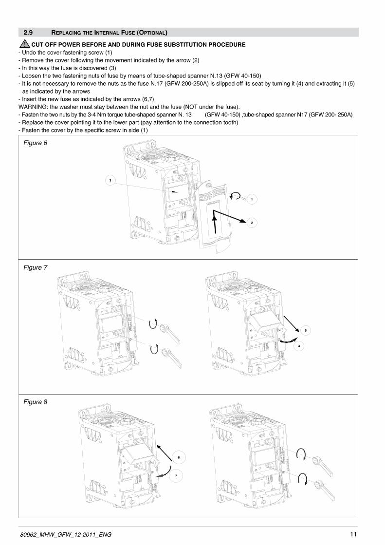
CUT OFF POWER BEFORE AND DURING FUSE SUBSTITUTION PROCEDURE- Undo the cover fastening screw (1) - Remove the cover following the movement indicated by the arrow (2)- In this way the fuse is discovered (3)- Loosen the two fastening nuts of fuse by means of tube-shaped spanner N.13 (GFw 40-150)- It is not necessary to remove the nuts as the fuse N.17 (GFw 200-250A) is slipped off its seat by turning it (4) and extracting it (5)
as indicated by the arrows- Insert the new fuse as indicated by the arrows (6,7)wARNING: the washer must stay between the nut and the fuse (NOT under the fuse).- Fasten the two nuts by the 3-4 Nm torque tube-shaped spanner N. 13 (GFw 40-150) ,tube-shaped spanner N17 (GFw 200- 250A)- Replace the cover pointing it to the lower part (pay attention to the connection tooth)- Fasten the cover by the specific screw in side (1)
2.9 rePlacing the internal fuse (oPtional)
6
7
4
5
1
2
3
Figure 6
Figure 7
Figure 8
12 80962_MHW_GFW_12-2011_ENG
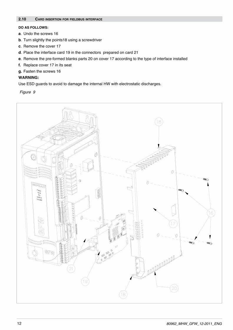
DO AS FOLLOWS:
a. Undo the screws 16b. Turn slightly the points18 using a screwdriverc. Remove the cover 17d. Place the interface card 19 in the connectors prepared on card 21e. Remove the pre-formed blanks parts 20 on cover 17 according to the type of interface installedf. Replace cover 17 in its seatg. Fasten the screws 16WARNING:Use ESD guards to avoid to damage the internal Hw with electrostatic discharges.
Figure 9
2.10 carD insertion for fielDbus interface

1380962_MHW_GFW_12-2011_ENG
CARRY OUT THE FOLLOWING STEPS:a. Remove the master module side cover by undoing the fastening screwsb Connect the flat cables supplied with the expansions to CPU card by inserting them into the appropriate connectors.c. Fix the side cover of the master with the specific screws d. Remove the front cover of the expansion modules undoing the fastening screw of the cover and correctly install the master module and the expansion module to the panel as described at paragraph 2.4.e. Fasten the screw to secure the product in position.f. Connect the two flat cables from the CPU card by inserting them into the correct connector of expansion.g. Ensure the flat ribbon cables remain parallel - do not twist.h. Do not pull the flat cable to avoid to damage it.i. Place the flat cable into the product and close the front cover of expansions.j. Check the front covers are properly closed with the screws.
Figure 10
2.11 connection of exPansion moDules (for biPhase or triPhase configuration)
14 80962_MHW_GFW_12-2011_ENG
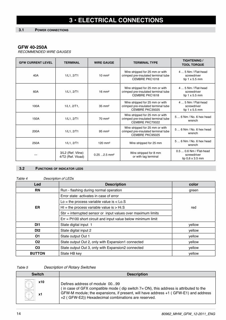
Table 5 Description of Rotary Switches
3 • ELECTRICAL CONNECTIONS3.1 Power connections
Table 4 Description of LEDs
GFW 40-250ARECOMMENDED WIRE GAUGES
Led Description colorRN Run - flashing during normal operation green
ER
Error state: activates in case of error
redLo = the process variable value is < Lo.SHI = the process variable value is > Hi.SSbr = interrupted sensor or input values over maximum limits Err = Pt100 short circuit and input value below minimum limit
DI1 State digital input 1 yellowDI2 State digital input 2 yellowO1 State output Out 1 yellowO2 State output Out 2, only with Expansion1 connected yellowO3 State output Out 3, only with Expansion2 connected yellow
BUTTON State HB key yellow
Switch Description
Defines address of module 00...99( in case of GFX compatible mode ( dip switch 7= ON), this address is attributed to the GFw-M module; the expansions, if present, will have address +1 ( GFw-E1) and address +2 ( GFw-E2)) Hexadecimal combinations are reserved.
x10
x1
3.2 functions of inDicator leDs
GFW CURRENT LEVEL TERMINAL WIRE GAUGE TERMINAL TYPE TIGHTENING / TOOL TORQUE
40A 1/L1, 2/T1 10 mm²wire stripped for 25 mm or with
crimped pre-insulated terminal tube CEMBRE PKC1018
4 ... 5 Nm / Flat-head screwdriver
tip 1 x 5.5 mm
60A 1/L1, 2/T1 16 mm²wire stripped for 25 mm or with
crimped pre-insulated terminal tube CEMBRE PKC1618
4 ... 5 Nm / Flat-head screwdriver
tip 1 x 5.5 mm
100A 1/L1, 2/T1, 35 mm²wire stripped for 25 mm or with
crimped pre-insulated terminal tube CEMBRE PKC35025
4 ... 5 Nm / Flat-head screwdriver
tip 1 x 5.5 mm
150A 1/L1, 2/T1 70 mm²wire stripped for 25 mm or with
crimped pre-insulated terminal tube CEMBRE PKC70022
5 ... 6 Nm / No. 6 hex head wrench
200A 1/L1, 2/T1 95 mm²wire stripped for 25 mm or with
crimped pre-insulated terminal tube CEMBRE PKC95025
5 ... 6 Nm / No. 6 hex head wrench
250A 1/L1, 2/T1 120 mm² wire stripped for 25 mm 5 ... 6 Nm / No. 6 hex head wrench
--- 3/L2 (Ref. Vline)4/T2 (Ref. Vload) 0.25 ...2.5 mm² wire stripped for 8 mm
or with tag terminal
0.5 ... 0.6 Nm / Flat-head screwdriver
tip 0,6 x 3.5 mm

1580962_MHW_GFW_12-2011_ENG
3.2 InPut/outPut connections3.3 DescriPtion InPut/outPut
mV / TC input(optional)
Top View
(Ref. V_load) 4 / T2
J 10
3 / L2 (Ref. V_line)
KB-ADLkeypad connector
Address x 10Address x 1
Line / load voltage connector
Protection fan
1 / L1“Line” Connection
1 / L1“Line” Connection
Screw front cover(allows access to fuse)
Magnetic areakeypadfixingKB-ADL(only GFw-M model)
IN2
IN3
IN4
IN5
J4
2 / T1“Load” Connection
2 / T1“Load”
Connection
2 / T1“Load”
Connection
IN1- Analog input connector PID (optional)
INA- Control analog input connector
Address Rotary Switch
Key HB
Digital input
Status Led
Supply
Outputs
Optional outputs
COM (OUT 5 - 8)OUT 5OUT 6OUT 7OUT 8OUT 9 (Relay N.O.)
OUT 10 (Relay N.O.)
+24 vdcGND-SUPPLYEARTH
EARTHI1 -I1 +IN1 (RTD)
+INDIG 1+INDIG 2+INDIG 3 (PwM input)GND - INDIG
RUN............ (green)ERROR.......(red) DI1.............. (yellow) DI2.............. (yellow)01................(yellow)02................(yellow)03................(yellow)BUTTON..... (yellow)
J1
J2
J3
J5
J6
OUT +5 V (Potentiometer)+ IN SHUNT - mAGND - INPUT
Low view Without option
Fieldbus
Low view With option
Fieldbus
Protection fan
GND SUPPLY 24 vdc GND
SUPPLY24 vdc
J7fan power supply
J7fan power supply
Connector boardFieldbus PORT 2 (optional)
J8, J9Connector RJ10serial RS485Modbus (PORT 1)
J8, J9Connector RJ10serial RS485Modbus (PORT 1)
Dip Switchserial line
Dip Switchserial line
Figure 11

16 80962_MHW_GFW_12-2011_ENG
LOAD
LOAD
LOAD
LOAD
1
5
4
3
2 O5
O6
O7
O8
Com 5√8
V
I
+ + + +
Outputs 5...8 logic/continuous typeLogic outputs 18...36Vdc, max 20mAContinuous outputs: voltage (default) 0/2...10V, max 25mA current0/4...20mA,max500Ω
0,2 - 2,5mm2 24-14AWG
0,25 - 2,5mm2 23-14AWG
Figure 12 Connector J1
Table 6
Figure 13 Connection scheme for logic/continuous outputs
Table 7
3.4 connector J1 outPuts 5...10
1
2
3
4
5
6
7
8
9
If auxiliary outputs (O5...O8), are present, connector J1a becomes J1.
PIN
12345
Name
Com 5-8O5O6O7O8
Continuous (-)(+)(+)(+)(+)
Logic Outputs common
Output 5Output 6Output 7Output 8
Decription
J1a
J1

1780962_MHW_GFW_12-2011_ENG
when using the continuous “C” output option, voltage or current is set using jumper links on the board (Figure 14 refers).
Figure 14 Connection for logic/continuous utputs

18 80962_MHW_GFW_12-2011_ENG
Outputs 5...8 relay typeOutputs Out 5...8 relay Ir = 3A max, NOV = 250V/30Vdc cos = 1; I = 12A max
Outputs 9, 10 relay typeOutputs Out 9, 10 relay 5A max, V = 250V/30Vdc cosj = 1; I = 5A max
LOAD
O8
Com 5√8Ir
I
O7O6O52
1
345
V
LOAD
LOAD
LOAD
Figure 16 Connection scheme for relay outputs
Figure 17 Connection scheme for relay outputs
Table 9
Table 10
Outputs 5...8 triac typeTriac outputs Vac = 24...230Vac, max 1A
LOAD
O8
Com 5√8
N
L
O7O6O5
LOAD
LOAD
LOAD
21
345
Vac
Figure 15 Connection scheme for triac outputs
Table 8
O9
6
V
V
LOAD
LOAD
7
8
9O10
Com O9
Com O10
I
I
PIN
12345
Name
Com 5-8O5O6O7O8
Decription
Outputs commonOutput 5Output 6Output 7Output 8
PIN
12345
Name
Com 5-8O5O6O7O8
Description
Outputs commonOutput 5Output 6Output 7Output 8
PIN
1234
Name
Com O9O9
Com O10O10
Description
Output common O9Output O9
Output common O10Output O10

1980962_MHW_GFW_12-2011_ENG
3.5 Connector J2 Power suPPly
Table 14
PIN
1234
Name
+INDIG1+INDIG2+INDIG3
GND
Description
Digital Input 1 (5...32Vdc)Digital Input 2 (5...32Vdc)Digital Input 3 (5...32Vdc)
GND common
Figure 20
3.6 Connector J2 Digital inPut
Table 13
0,14 - 0,5mm2 28-20AWG
0,25 - 0,5mm2 23-20AWG
Figure 21 Connection scheme for digital inputs
Figure 18
Table 11
0,2 - 2,5mm2 24-14AWG
0,25 - 2,5mm2 23-14AWG
Figure 19
Table 12
PIN
123
Name
+24 VdcGND
EARTH
Decription
24V Supply
Ground EMC

20 80962_MHW_GFW_12-2011_ENG
Figure 22
Table 15
0,14 - 0,5mm2 28-20AWG
0,25 - 0,5mm2 23-20AWG
3.7 Connector J3 auxiliary inPuts 5...8
Table 16
PIN
12345678
Name
I2-I2+I3-I3+I4-I4+I5-I5+
Description
Auxiliary input 2
Auxiliary input 3
Auxiliary input 4
Auxiliary input 5
Figure23 AuxiliaryinputsI5-I8(60mV/TC)
12
12
13
13
14
14
15
15
+
-
+
-
+
-
+
-

2180962_MHW_GFW_12-2011_ENG
3.8 Connector J5 analog inPut control
Table 18
PIN
1
234
Name
+5V_Out
+INSHUNT
GND
Description
Supply output 5V potentiometerControl voltage Input Shunt for input mAGND control signal
Figure 25 Connection scheme
Figure 24
Table 17
0,2 - 2,5mm2 24-14AWG
0,25 - 2,5mm2 23-14AWG

22 80962_MHW_GFW_12-2011_ENG
3.9 Connctor J6: PiD Input
Table 21
PIN
1234
Linear input60mV/Tc
(wire Shield)I1-I1+
Not connected
Linear input1V/20mA
(wire Shield)I1-
Not connectedIN1 (+)
InputPt100
(wire Shield)I1+I1+IN1
Figura 26
Table 19
0,2 - 2,5mm2 24-14AWG
0,25 - 2,5mm2 23-14AWG
Table 20PIN
1234
Name
EARTHl1-l1+lN1
Description
EMC earth (for shielded cable)Negative Input Positive Input TC and RTD3rd wire RTD, Positive IN mA,
Figure 27 Connection scheme for 60mV TC/linear input
Figure 28 Connection scheme for Pt100 input
Figure 29 Connection scheme for 1V/20mA linear input

2380962_MHW_GFW_12-2011_ENG
Figure 30
3.10 Description of dip-switches
12
34
56
7
ON
dip-switches
12345
67
Description
Connection type: (see table 23) Connection type: (see table 23) Connection type: (see table 23) Connection type: (see table 23) OFF = resistive load ON = inductive load (transformer primary control) ON = reset factory configuration ON = Geflex simulation function
Table 22
IMPORTANT!
AFTER SETTING THE REQUIRED DIP-SwITCH CONFIGURATION, RUN THE FOLLOwING PARAMETER
INITIALIZATION PROCEDURE ONCE:
- CHECK THE CORRECT SETTING OF DIPS 1-2-3-4-5
- SET DIP 6 TO “ON” (FACTORY CONFIGURATION)
- POwER THE DEVICE wITH 24 VDC
- wAIT FOR CORRECT AND REGULAR FLASHING OF THE GREEN RUN LED
- SET DIP 6 TO “OFF”
- THE DEVICE IS CORRECTLY CONFIGURED
Table 23
OFF
: res
istive
load
O
N :i
nduc
tive
load
(tr
ansf
orm
er p
rimar
y co
ntro
l)
Request modules
GFw
mas
ter
GFw
Exp
ansi
on 1
GFw
Exp
ansi
on 2
Dip 1 Dip 2 Dip 3 Dip 4 Dip 5 Connection typeOFF OFF OFF OFF OFF/ON Three Single-phase load x (*) (*)OFF ON OFF OFF OFF/ON Three Independent single-phase load in open delta x x xON ON OFF OFF OFF/ON 3-phase load open delta/star load with neutral x x xON ON ON OFF OFF/ON 3-phase load closed delta x x xON OFF OFF ON OFF/ON 3-phase star load without neutral x x x
ON OFF OFF OFF OFF 3-phase load with 2-phase command x x
(*) Each expansion lets you add a single-phase load (up to a maximum of 3 total loads).

24 80962_MHW_GFW_12-2011_ENG
3.11 Serial communication Ports
Port1 (local bus): Modbus serial interface – connectors S1, S2.
Figure 31
Table 24
4
32 1
Cable type: flat telephone cable for pin 4-4 conductor 28AwG
Connector S1/S2RJ10 4-4 pin Nr. Pin Name
1
2
3
4
GND1 (**)
Tx/Rx+
Tx/Rx-
+V (reserved)
Description
-
Data reception/transmission (A+)
Data reception/transmission (B-)
-
Note
(*) Insert the RS485 line termination in the last device on the Modbus line, see dip-switches.
(**) Connect the GND signal between Modbus devices with a line distance > 100 m.
S1
S2
Port 2(Fieldbusoptiobalboard)
Port 1(Fieldbusoptiobalboard)

2580962_MHW_GFW_12-2011_ENG
Port2 (fieldbus): connectors S4, S5 MODBUS RTU/MODBUS RTU
Figure 32 Port2: Fieldbus Modbus RTU/Modbus RTU interface
Table 25
4
32 1
Cable type: flat telephone cable for pin 4-4 conductor 28AwG
Connector S4/S5RJ10 4-4 pin Nr. Pin Name
1
2
3
4
GND1 (**)
Tx/Rx+
Tx/Rx-
+V (reserved)
Description
-
Data reception/transmission (A+)
Data reception/transmission (B-)
-
Note
(*) Insert the line termination in the last device on the Modbus line.
(**) Connect the GND signal between Modbus devices with a line distance > 100 m.
Connector S4
Connector S5
Line termination (*)

26 80962_MHW_GFW_12-2011_ENG
Port2 (fieldbus): connectors S4, S5 MODBUS RTU/Profibus DP
Figure 33 Port2: Fieldbus Modbus RTU/Profibus DP interface
Table 26
Table 27
4
32 1
Cable type: flat telephone cable for fin 4-4 conductor 28AwG
Connector S4RJ10 4-4 pin Nr. Pin Name
1
2
3
4
GND1 (**)
Rx/Tx+
Rx/Tx-
+V (reserved)
Cable type: Shielded 1 pair 22AwG conforming to PROFIBUS.
Connector S5D-SUB 9 pins male
Nr. Pin Name
123456789
SHIELDM24V
RxD/TxD-Pn.c.
DGNDVP
P24VRxD/TxD-N
n.c.
Description
-
Data reception/transmission (A+)
Data reception/transmission (B-)
-
Description
EMC protectionOutput voltage - 24V
Data reception/transmissionn.c.
Data GroundPositive power supply +5V
Output voltage +24VData reception/transmission
n.c.1 2 3 4 5
6 7 8 9
390 �
Data line
Data line
390 �
220 �
RxD/TxD-P (3)
RxD/TxD-N (8)
VP (6)
DGND (5)
Connect the terminal resistances as shown in the figure.
Note
Note
(**) Connect the GND signal between Modbus devices with a line distance > 100 m.
S4 female connector
S5 female connector
Yellow LedRed LedGreen Led

2780962_MHW_GFW_12-2011_ENG
Port2 (fieldbus): connectors S4, S5 MODBUS RTU/CANopen or EUROMAP 66
Figure 34 Port2: Fieldbus Modbus RTU/CANOpen interface or EUROMAP 66
Table 28
Table 29
4
32 1
Cable type: flat telephone cable for fin 4-4 conductor 28AwG
Connector S4RJ10 4-4 pin Nr. Pin Name
1
2
3
4
GND1 (**)
Rx/Tx+
Rx/Tx-
+V (reserved)
Cable type: Shielded 2 pairs 22/24AwG conforming to CANopen.
Connector S5D-SUB 9 pins female
Nr. Pin Name
123456789
-CAN_L
CAN_GND-
(CAN_SHLD)(GND)CAN_H
-(CAN_V+)
Description
-
Data reception/transmission (A+)
Data reception/transmission (B-)
-
Description
ReservedCAN_L bus line (domination low)
CAN GroundReserved
Optional CAN ShieldOptional Ground
CAN_H bus line (domination high)Reserved
Optional CAN external positive supply (dedicated for supply of transceiver
and optocouplers, if galvanic isolation of the bus node applies)
5 4 3 2 1
9 8 7 6
. . . . . . . .node 1 node n
CAN_L
CAN_H
CAN Bus Line
120
�
120
�
Connect the terminal resistances as shown in the figure.
Note
Note
(**) Connect the GND signal between Modbus devices with a line distance > 100 m.
S4 female connector
S5 male connector
Red LedGreen Led

28 80962_MHW_GFW_12-2011_ENG
Port2 (fieldbus): connectors S4, S5 MODBUS RTU/DeviceNet
Figure35 Port2:FieldbusModbusRTU/DeviceNetinterface
Table 30
Table 31
4
32 1
Cable type: flat telephone cable for fin 4-4 conductor 28AwG
Connector S4RJ10 4-4 pin Nr. Pin Name
1
2
3
4
GND1 (**)
Rx/Tx+
Rx/Tx-
+V (reserved)
Cable type: Shielded 2 pairs 22/24AwG conforming to DeviceNet.
Connector S5MC-1,5/5 - ST1-5,08
5 pole female
Nr. Pin Name
12345
V-CAN_LSHIELDCAN_H
V+
Description
-
Data reception/transmission (A+)
Data reception/transmission (B-)
-
Description
Negative power supplyLow signal
Shieldhigh signal
Positive power supply
Connecta120Ω/1/4Wresistancebetween the “CAN_L” and “CAN_H” signals at each end of the DeviceNet network.
Note
Note
(**) Connect the GND signal between Modbus devices with a line distance > 100 m.
S4 female connector
S5 male connector
Red Led
Green Led
V-
CAN_L
SHIELD
CAN_H
V+
1 2 3 4 5

2980962_MHW_GFW_12-2011_ENG
Table 33
Port2 (fieldbus): connectors S4, S5 Modbus RTU / Ethernet Modbus TCP
Figure 36 Port2: Modbus RTU / Ethernet Modbus TCP interface
Table 32
4
32 1
Cable type: flat telephone cable for pin 4-4 conductor 28AwG
Connector S4RJ10 4-4 pin Nr. Pin Name
1
2
3
4
GND1 (**)
Rx/Tx+
Rx/Tx-
+V (reserved)
Cable type: Use standard category 6 cable according to TIA/EIA-568A
Connector S5RJ45
Nr. Pin Name
12345678
TX+TX-RX+n.c.n.c.RX-n.c.n.c.
Description
-
Data reception/transmission (A+)
Data reception/transmission (B-)
-
Description
Data + transmissionData - transmission
Data + reception
Data - reception
Note
Note
(**) Connect the GND signal between Modbus devices with a line distance > 100 m.
S4 female connector
S5 female connector
Yellow LedGreen Led
8
1

30 80962_MHW_GFW_12-2011_ENG
Table 35
Port2 (fieldbus): connectors S4, S5 Modbus RTU / Ethernet IP
Figure 37 Port2: Modbus RTU / Ethernet IP interface
Table 34
Cable type: Use standard category 6 cable according to TIA/EIA-568A
Connector S5RJ45
Nr. Pin Name
12345678
TX+TX-RX+n.c.n.c.RX-n.c.n.c.
Description
Data + transmissionData - transmission
Data + reception
Data - reception
Note
8
1
4
32 1
Cable type: flat telephone cable for pin 4-4 conductor 28AwG
Connector S4RJ10 4-4 pin Nr. Pin Name
1
2
3
4
GND1 (**)
Rx/Tx+
Rx/Tx-
+V (reserved)
Description
-
Data reception/transmission (A+)
Data reception/transmission (B-)
-
Note
(**) Connect the GND signal between Modbus devices with a line distance > 100 m.
S4 female connectorS5 female connector
Green led Packet activity Yellow led Link integrity
3180962_MHW_GFW_12-2011_ENG
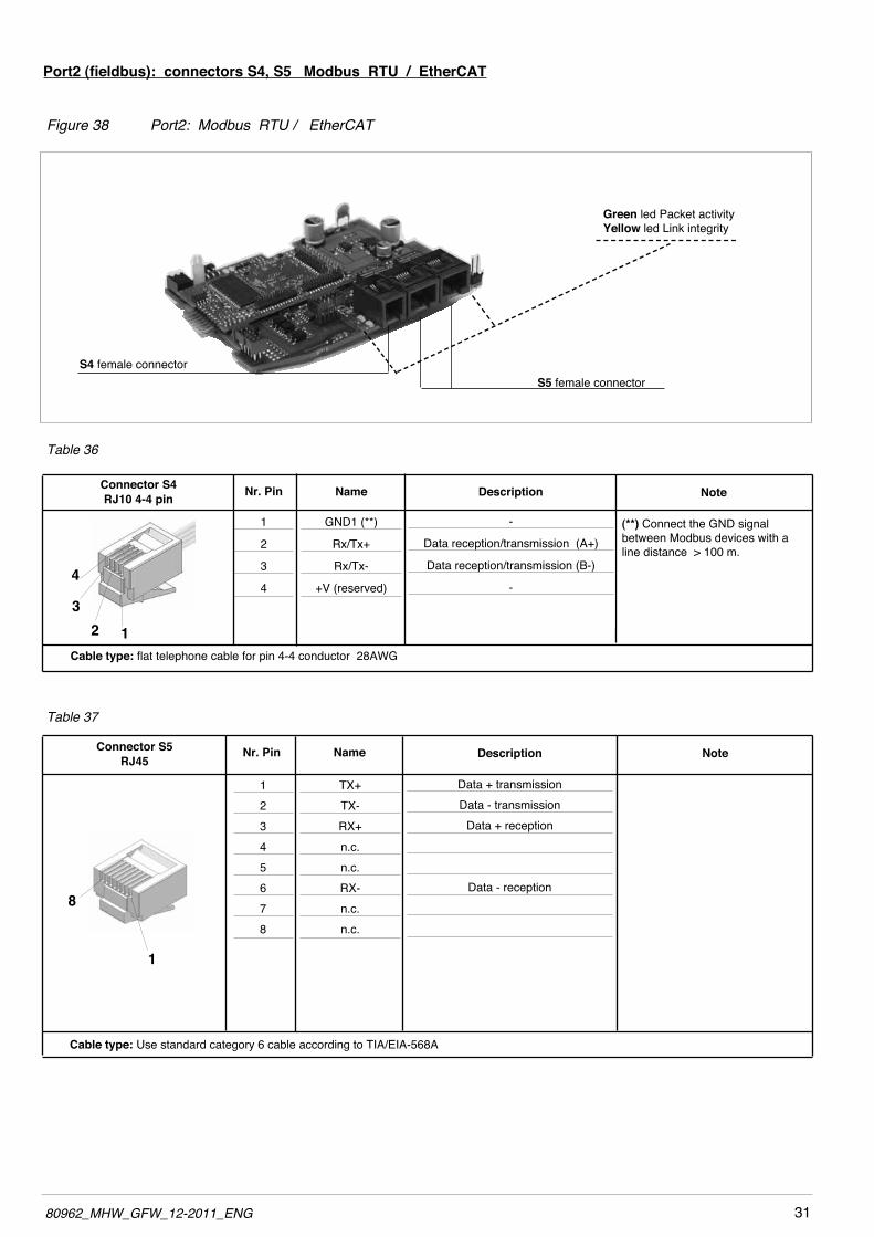
Table 37
Port2 (fieldbus): connectors S4, S5 Modbus RTU / EtherCAT
Figure 38 Port2: Modbus RTU / EtherCAT
Table 36
Cable type: Use standard category 6 cable according to TIA/EIA-568A
Connector S5RJ45
Nr. Pin Name
12345678
TX+TX-RX+n.c.n.c.RX-n.c.n.c.
Description
Data + transmissionData - transmission
Data + reception
Data - reception
Note
8
1
4
32 1
Cable type: flat telephone cable for pin 4-4 conductor 28AwG
Connector S4RJ10 4-4 pin Nr. Pin Name
1
2
3
4
GND1 (**)
Rx/Tx+
Rx/Tx-
+V (reserved)
Description
-
Data reception/transmission (A+)
Data reception/transmission (B-)
-
Note
(**) Connect the GND signal between Modbus devices with a line distance > 100 m.
S4 female connectorS5 female connector
Green led Packet activity Yellow led Link integrity
32 80962_MHW_GFW_12-2011_ENG
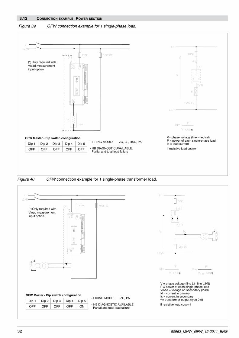
3.12 connection examPle: Power section
Figura39 GFWconnectionexamplefor1single-phaseload.
Figura 40 GFW connection example for 1 single-phase transformer load,
(*) Only required with Vload measurement input option.
V= phase voltage (line - neutral)P = power of each single-phase loadId = load currentif resistive load cosj=1
V = phase voltage (line L1- line L2/N)P = power of each single-phase loadVload = voltage on secondary (load)Id = current in primaryIs = current in secondaryη= transformer output (type 0,9)if resistive load cosj=1
(*) Only required with Vload measurement input option.
j
- FIRING MODE: ZC, BF, HSC, PA
- HB DIAGNOSTIC AVAILABLE: Partial and total load failure
GFW Master - Dip switch configuration
Dip 1 Dip 2 Dip 3 Dip 4 Dip 5OFF OFF OFF OFF OFF
- FIRING MODE: ZC, PA
- HB DIAGNOSTIC AVAILABLE: Partial and total load failure
GFW Master - Dip switch configuration
Dip 1 Dip 2 Dip 3 Dip 4 Dip 5OFF OFF OFF OFF ON
j j
3380962_MHW_GFW_12-2011_ENG
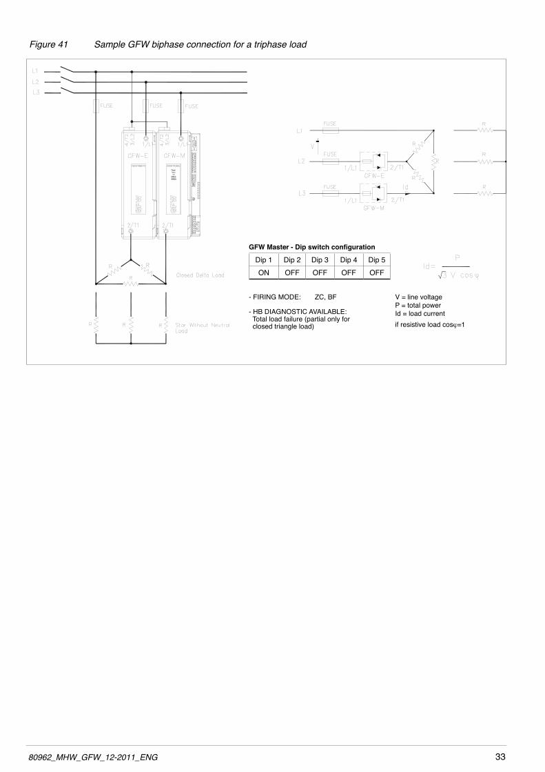
Figure 41 Sample GFW biphase connection for a triphase load
V = line voltageP = total powerId = load currentif resistive load cosj=1
- FIRING MODE: ZC, BF
- HB DIAGNOSTIC AVAILABLE: Total load failure (partial only for closed triangle load)
GFW Master - Dip switch configuration
Dip 1 Dip 2 Dip 3 Dip 4 Dip 5ON OFF OFF OFF OFF

34 80962_MHW_GFW_12-2011_ENG
Figura42 GFWconnectionexamplefor13-phasecloseddeltaload
Figura43 GFWconnectionexamplefor13-phasecloseddeltaloadwithtransformer
(*) Only required with Vload measurement input option.
V= line voltageP = total powerId = load currentif resistive load cosj=1
V = phase voltage (line L1- line L2/N)P = power of each single-phase loadVload = voltage on secondary (load)Id = current in primaryIs = current in secondaryη= transformer output (type 0,9)if resistive load cosj=1
- FIRING MODE: ZC, BF, PA
- HB DIAGNOSTIC AVAILABLE: Partial and total load failure
GFW Master - Dip switch configuration
Dip 1 Dip 2 Dip 3 Dip 4 Dip 5ON ON ON OFF OFF
- FIRING MODE: ZC, PA
- HB DIAGNOSTIC AVAILABLE: Partial and total load failure
GFW Master - Dip switch configuration
Dip 1 Dip 2 Dip 3 Dip 4 Dip 5ON ON ON OFF ON
j
jj

3580962_MHW_GFW_12-2011_ENG
Figura44 GFWconnectionexamplefor13-phasestarloadwithoutneutral
Figura45 GFWconnectionexamplefor13-phasestarloadwithoutneutralwithtransformer
V = phase voltage (line L1- line L2/N)P = power of each single-phase loadVload = voltage on secondary (load)Id = current in primaryIs = current in secondaryη= transformer output (type 0,9)if resistive load cosj=1
(*) Only required with Vload measurement input option.
V= line voltageVd= load voltageP = total powerId = load currentif resistive load cosj=1
- FIRING MODE: ZC, BF, PA
- HB DIAGNOSTIC AVAILABLE: Partial and total load failure
GFW Master - Dip switch configuration
Dip 1 Dip 2 Dip 3 Dip 4 Dip 5ON OFF OFF ON OFF
- FIRING MODE: ZC, PA
- HB DIAGNOSTIC AVAILABLE: Partial and total load failure
GFW Master - Dip switch configuration
Dip 1 Dip 2 Dip 3 Dip 4 Dip 5ON OFF OFF ON ON
j j
j

36 80962_MHW_GFW_12-2011_ENG
Figue46GFWconnectionexamplefor13-phasestarloadwithneutral
Figure47 GFWconnectionexamplefor13-phaseloadopendelta
(*) Only required with Vload measurement input option.
(*) Only required with Vload measurement input option.
V= line voltageVd= load voltageP = total powerId = current in 3-phase loadif resistive load cosj=1
V= line voltageP = power of each single-phase loadId = load currentif resistive load cosj=1
- FIRING MODE: ZC, BF, HSC, PA
- HB DIAGNOSTIC AVAILABLE: Partial and total load failure
GFW Master - Dip switch configuration
Dip 1 Dip 2 Dip 3 Dip 4 Dip 5ON ON OFF OFF OFF
- FIRING MODE: ZC, BF, HSC, PA
- HB DIAGNOSTIC AVAILABLE: Partial and total load failure
GFW Master - Dip switch configuration
Dip 1 Dip 2 Dip 3 Dip 4 Dip 5ON ON OFF OFF OFF
j
j

3780962_MHW_GFW_12-2011_ENG
Figure48 GFWconnectionexamplefor3independentloadsinopendelta,3-phaselinewithoutneutral
Figure49 ExampleofGFW3-PHwiringfor3indipendentsingle-phaseloads
It is possible to connect three single-phase loads also to three different line voltages, between line to line or line to neutral. It is possible to manage by Fieldbus different power values for each one of the three loads.
V= line voltageP = power of each single-phase loadId = load currentif resistive load cosj=1
(*) Only required with Vload measurement input option.
V= line voltageP = power of each single-phase loadId = load currentif resistive load cosj=1
- FIRING MODE: ZC, BF, HSC, PA
- HB DIAGNOSTIC AVAILABLE: Partial and total load failure
GFW Master - Dip switch configuration
Dip 1 Dip 2 Dip 3 Dip 4 Dip 5OFF ON OFF OFF OFF
- FIRING MODE: ZC, BF, HSC, PA
- HB DIAGNOSTIC AVAILABLE: Partial and total load failure
GFW Master - Dip switch configuration
Dip 1 Dip 2 Dip 3 Dip 4 Dip 5OFF OFF OFF OFF OFF
j
j

38 80962_MHW_GFW_12-2011_ENG
Figure50 ExampleofGFW-2PHfor2indipendentsinglephaseloads
It is possible to connect two single-phase loads also to different line voltages, between line to line or line to neutral It is possible to manage different power values for each one of the two loads.
V= line voltageP = power of each single-phase loadId = load currentif resistive load cosj=1
- FIRING MODE: ZC, BF, HSC, PA
- HB DIAGNOSTIC AVAILABLE: Partial and total load failure
GFW Master - Dip switch configuration
Dip 1 Dip 2 Dip 3 Dip 4 Dip 5OFF OFF OFF OFF OFF
j

3980962_MHW_GFW_12-2011_ENG
Trigger modesThe GFw has the following power control modes:- modulation via variation of number of conduction cycles with zero crossing trigger.- modulation via variation of phase angle.
Zero Crossing modeThis function eliminates EMC noise. This mode controls power on the load via a series of conduction ON and non conduction OFF cycles.ZC- constantcycletime(Tc≥1sec,settablefrom1to200sec) Cycle time is divided into a series of conduction and non conduction cycles in proportion to the power value to be transferred to the load.
Figure 51
For example, if Tc = 10sec, if the power value is 20% there is conduction for 2 sec (100 conduction cycles @ 50Hz) and non conduction for 8 sec (400 non conduction cycles @ 50Hz).
BF - variable cycle time (GTT) This mode controls power on the load via a series of conduction ON and non conduction OFF cycles. The ratio of the number of ON cycles to OFF cycles is proportional to the power value to be supplied to the load. The CT repeat period is kept to a minimum for each power value (whereas in ZC mode the period is always fixed and not optimized).
NOTES: USE WITH INDUCTIVE LOADS AND TRANSFORMERS
a) when the GFw is working it is not allowed to open neither the connection between GFw and the transformer nor the connection between the transformer and the loadb) The maximum current controllable by the device is less than the product’s rated value (see technical data).c) In ZC and BF trigger mode, use the Delay-triggering function to limit peak magnetization current.d) In PA trigger mode, use the Softstart function.e) DO NOT use HSC trigger mode.f) DO NOT connect RC snubbers in parallel to the transformer primary.g) Always set Dip-Switch 5 to ON (and run the initial configuration procedure described in paragraph 3.7)

40 80962_MHW_GFW_12-2011_ENG
HSC - Half single cycle This mode corresponds to Burst Firing that includes ON and OFF half-cycles.
NB: This mode is NOT allowed with inductive loads (transformers).
Figure 52
parameter defines the minimum number of conduction cycles settable from 1 to 10.In the following example, the parameter = 2.
Phase angle (PA)This mode controls power on the load via modulation of trigger angle qif power to be transferred to the load is 100%, q = 180°if power to be transferred to the load is 50%, q = 90°
Figure 54
Figure 53
Example of operation in HSC mode with power at 33 and 66%.
Resistive load Inductive load
4180962_MHW_GFW_12-2011_ENG
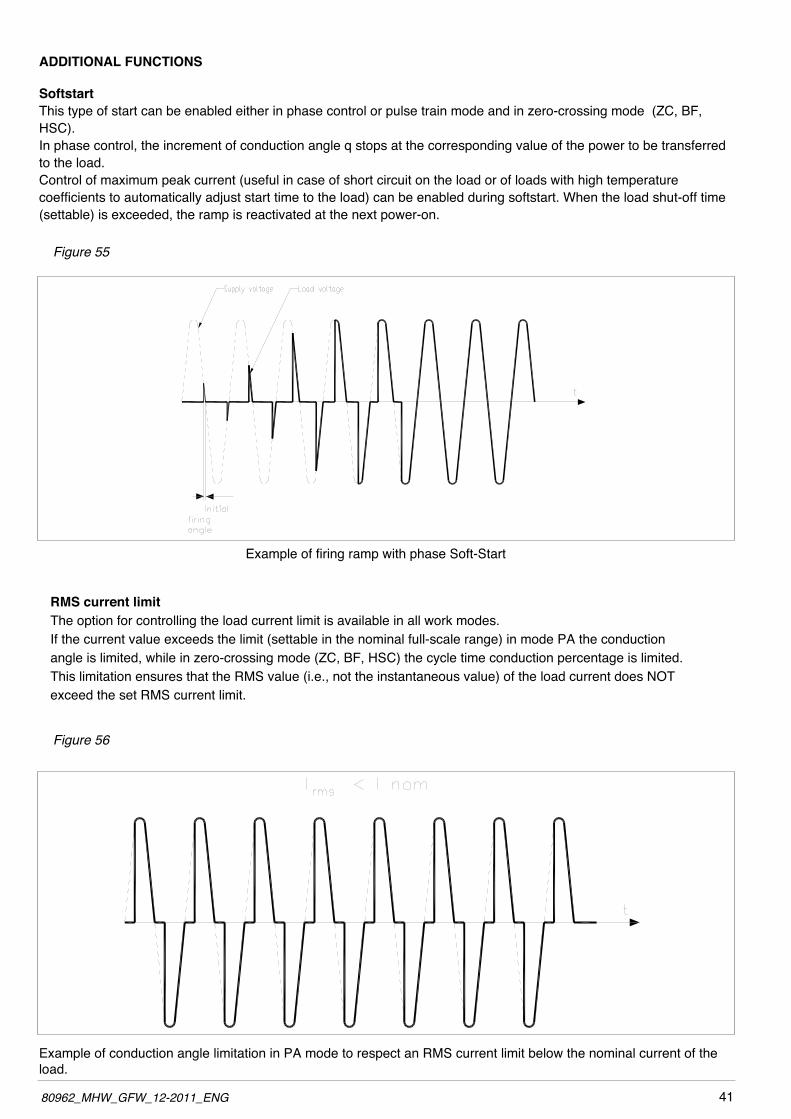
ADDITIONAL FUNCTIONS
SoftstartThis type of start can be enabled either in phase control or pulse train mode and in zero-crossing mode (ZC, BF, HSC).In phase control, the increment of conduction angle q stops at the corresponding value of the power to be transferred to the load.Control of maximum peak current (useful in case of short circuit on the load or of loads with high temperature coefficients to automatically adjust start time to the load) can be enabled during softstart. when the load shut-off time (settable) is exceeded, the ramp is reactivated at the next power-on.
Figure 55
Example of firing ramp with phase Soft-Start
RMS current limitThe option for controlling the load current limit is available in all work modes. If the current value exceeds the limit (settable in the nominal full-scale range) in mode PA the conduction angle is limited, while in zero-crossing mode (ZC, BF, HSC) the cycle time conduction percentage is limited.This limitation ensures that the RMS value (i.e., not the instantaneous value) of the load current does NOT exceed the set RMS current limit.
Figure 56
Example of conduction angle limitation in PA mode to respect an RMS current limit below the nominal current of the load.

42 80962_MHW_GFW_12-2011_ENG
DT - “Delay triggering” (for ZC, BF control modes only) Settable from 0° to 90°. Useful for inductive loads (transformer primaries) to prevent current peak that in certain cases could trip the high-speed fuses that protect the SCRs.
Figure 57
Figure 58
Transient withOver-Current
Transient withoutOver-Current
Comparison of method to fire a transformer: Soft-Start Ramp (for PA mode) / Delay triggering (for ZC and BF mode)
Example of phase ramp to fire a transformer in PA mode
Example of firing with Delay-Triggering of a transformer in ZC mode
To conduct inductive loads controlled in PA mode, do not use delay triggering; instead, use the phase Soft-Start ramp.
Example of firing of inductive load with/without delay-triggering.

4380962_MHW_GFW_12-2011_ENG
4 • INSTALLATION OF “MODBUS” SERIAL NETWORKA network typically has a Master that “manages” communication by means of “commands,” and Slaves that carry out these commands.GFw modules is considered Slaves to the network master, which is usually a supervision terminal or a PLC.It is positively identified by means of a node address (ID) set on rotary switches (tens + units).A maximum of 99 GFw, modules can be installed in a serial network, with node address selectable from “01” to “99”ì.
GFw modules has a ModBus serial (Serial 1) and, optionally (see order code) a Fieldbus serial (Serial 2) with one of the following protocols: Modbus RTU, Profibus DP, CANopen, DeviceNet e Ethernet Modbus TCP.
The MODBUS RTU port 1 has the following factory settings (default):
Parameter Default RangeID 1 1...99BaudRate 19,2Kbit/s 1200...115kbit/sParity None parity/odd parity/noneStopBits 1 -DataBits 8 -
The following procedures are indispensable for the Modbus protocol.For the other protocols, see the specific Geflex manuals.The use of rotary switches (A...F) letters is for particular procedures described in the following paragraphs.Here are the tables showing them:
Procedure Positions of Description rotary switches Tens UnitsAutoBaud 0 0 It enables to set the correct BaudRate value automatically detecting the master transmission frequency

44 80962_MHW_GFW_12-2011_ENG
4.1 “AUTOBAUD SERIAL 1” sequence
FunctionAdapt the serial communication speed and parity of the GFw modules to the connected supervision terminal or PLC.
Green LED L1 “STATUS” mentioned in the procedurecanvaryitsbehaviorbasedonparameterLd.1,whichissettoadefaultvalueof16.
Procedure
1) Connect the serial cables for all modules on the network to serial 1 and to the supervision terminal.
2) Set the rotary switch on the GFw modules to be installed, or on all modules present in case of first installation, to position “0+0”.
3) Check that the green “STATUS” LEDs flash at high frequency (10Hz).
4) The supervision terminal must transmit a series of generic “MODBUS” read messages to the network.
5) The procedure is over when all of the green L1 “STATUS” LEDs on the GFw modules flash at a normal frequency (2Hz) (if parameter 197 Ld.1 = 16 as default).
The new speed parameter is saved permanently in each GFw; therefore, the “AUTOBAUD SERIAL 1” sequence does not have to be run at subsequent power-ups.
when the rotary switch is turned, the green “STATUS” LED stays on steadily for about 6 seconds, after which it resumes normal operation and saves the address.
INSTALLATION OF SERIAL NETWORK 1
ModBus
SETTING THE NODE ADDRESS
OPERATIVE FUNCTION
NO
The serial network communication speed is the same as for GFw.
?YES
“AUTOBAUD” SERIAL 1
SEQUENCE
Green “STATUS” LED flashes at 10 Hz

4580962_MHW_GFW_12-2011_ENG
INPUTSINA Analogic control inputsFunction Acquisition of % value for power control
Voltage Linear: 0,…,5Vdc, Ri>100KohmLinear: 0,…,10Vdc, Ri>100Kohm
Current Linear: 0/4…20mA, Ri =125ohmPotentiometric 1, ..., 10Kohm, max 10mA from 5Vdc power GFwIN1 Analog process inputs (option)Function Acquisition of process variableMax. error 0,2% f.s. ± 1 scale point at @ 25°CThermal drift < 100 ppm/°C of f.s. Sampling time 120 ms
Thermocouple Tc (ITS90) J,K,R,S,T (IEC 584-1,CEI EN 60584-1, 60584-2)Error cold junction comp. 0,1°/°C
Resistance thermometer RTD (ITS90) Pt100 (DIN 43760) Max line resistance 20ohm
VoltageLinear: 0,…,60mV, Ri>1Mohm 0,…,1V, Ri>1Mohma 32-segment custom linearization can be inserted
Current Linear: 0/4…20mA, Ri =50ohm a 32-segment custom linearization can be inserted
IN2,…,IN5 auxiliary analog inputs (option)Function Acquisition of variables (mV or Thermocouple)Accuracy 1% f.s. ± 1 scale point @ 25°C Sampling time 480 ms
Thermocouple Tc (ITS90) J,K,R,S,T (IEC 584-1,CEI EN 60584-1, 60584-2)Error cold junction comp 0,1°/°C
Voltage Linear: 0,…,60mV, Ri>1MohmLine Voltage measurement, Current /Voltage (optional) on load
RMS line voltage measurement functionLine voltage read 50-60Hz; voltage in range :90...530Vac for model with work voltage range 480Vac90...660Vac for model with work voltage range 600Vac
Accuracy RMS line voltage measurement 1% f.s. with neutral connected, 3% f.s. without neutralRMS current measurement function Load current read
Accuracy RMS current measurement 2% f.s. @25°C in start mode ZC e BF; in mode PA 3% f.s. withconduction angle >90°, 10% f.s. with conduction angle <90°
Function voltage measurement RMS on load Load voltage read
Accuracy RMS voltage measurement on load1% f.s. with VLOAD option measurement(Otherwise, the value is calculated from the values of line voltage and power delivered; accuracy 3% F.S.)
Current and Voltage sampling time 0,25 ms INDIG1,…,INDIG3 Digital inputs
Function
Configurable (default: disabled)only for INDIG3: PwM input (max 100Hz) to check the % value of power which depends on the cycle; this function lets you to set a power set point by means of a digital signal (ex. from PLC or controller with PwM output).
Type 5-30Vdc, 7mA isolation 1500VOUTPUTS
OUT1, …, OUT3 heat control connected directly to solid-state units
FunctionConfigurable (default: heat control)State of control is displayed by LED (O1, ,O3)OUT1 is connected to Master unit, OUT2 and OUT3 are connected to Expansion units
OUT5,...,OUT8 cooling control outputs (option)Function Configurable (default: cooling control)Relay Contact NO 3A, 250V/30Vdc cosφ =1
5 • TECHNICAL CHARACTERISTICS

46 80962_MHW_GFW_12-2011_ENG
Continuous0/2…10V (default), max 25mA short circuit protection 0/4…20mA, max. load 500ohm isolation 500V
Logic 24Vdc, > 18V a 20mA Triac 230V/ max 4A AC51 (1A for each channel)OUT9, OUT10 alarmFunction Function Configurable (default alarms)Relay Contact NO 5A, 250V/30Vdc cosφ =1
COMMUNICATIONS PORTSPORT KB-ADL
Function Serial comunication for KB-ADL terminal to display parameter programming
PORT1 (always present)Function Function Local serial communicationProtocol ModBus RTU Baudrate Settable 1200,…,115200, (default 19,2Kbit/s) Node address Node address Settable with rotary-switches
Type RS485 - isolation 1500V, double connector RJ10 telephone type 4-4
PORT2 (Fieldbus option) Function Fieldbus serial communication
Protocol
ModBus RTU, type RS485, baudrate 1200...115000Kbit/sCANOpen 10K…1Mbit/sDeviceNet 125K…0,5Mbit/sProfibus DP 9,6K...12 Mbit/sEthernet Modbus TCP 10/100Mbit/sEthernet IP 10/100Mbit/sEtherCAT 100Mbps
POWER (Solid-state relay)
CATEGORY OF USE(Tab. 2 EN60947-4-3)
AC 51 resistive or low inductance loadsAC 55b short wave infrared lamps (SwIR)AC 56a transformers, resistive loads with high temperature coefficient
Trigger mode
PA - load control via adjustment of firing phase angleZC - Zero Crossing with constant cycle time(settable in range 1-200sec)BF - Burst Firing with variable cycle time (GTT) optimized minimum.HSC - Half Single Cycle corresponds to Burst Firing that includes ON and OFF half-cycles.Useful for reducing flicker with short-wave IR loads (applied only to calibrate each time you change feedback mode.
Feedback mode
V Voltage feedback: proportional to RMS voltage value on load to compensate possible variations in line voltage.I Current feedback: proportional to RMS current value on load to compensate variations in line voltage and/or variations in load impedance.W Power feedback: proportional to real power value on load to compensate variations in line voltage and/or variations in load impedance. You have to calibrate each time you change feedback mode.
Max rated voltage 480Vac to 600Vac
work voltage range 90…530Vac (models 480V)90…660Vac (models 600V)
Non-repetitive voltage 1200Vp (models480V)1600Vp (models 600V)
Rated frequency 50/60Hz auto-determinationCritical Dv/dt with output deactivated 1000V/µsecHeld nominal voltage of on the impulse 4KVNominal current for short circuit condition 5KAProtection RC, extrarapid fuses for SCR
4780962_MHW_GFW_12-2011_ENG
Rated current AC51 non-inductive or slightly inductive loads, resistance furnaces
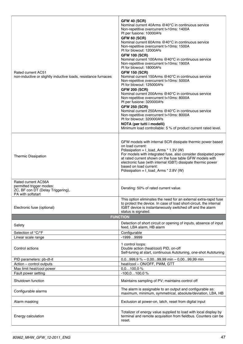
GFW 40 (SCR)Nominal current 40Arms @40°C in continuous serviceNon-repetitive overcurrent t=10ms: 1400AI²t per fusione: 10000A²sGFW 60 (SCR)Nominal current 60Arms @40°C in continuous serviceNon-repetitive overcurrent t=10ms: 1500AI²t for blowout: 12000A²sGFW 100 (SCR)Nominal current 100Arms @40°C in continuous serviceNon-repetitive overcurrent t=10ms: 1900AI²t for blowout: 18000A²sGFW 150 (SCR)Nominal current 150Arms @40°C in continuous serviceNon-repetitive overcurrent t=10ms: 5000AI²t for blowout: 125000A²sGFW 200 (SCR)Nominal current 200Arms @40°C in continuous serviceNon-repetitive overcurrent t=10ms: 8000AI²t per fusione: 320000A²sGFW 250 (SCR)Nominal current 250Arms @40°C in continuous serviceNon-repetitive overcurrent t=10ms: 8000AI²t for blowout: 320000A²sNOTA (per tutti i modelli)Minimum load controllable: 5 % of product current rated level.
Thermic Dissipation
GFw models with internal SCR dissipate thermic power based on load current: Pdissipation = I_load_Arms * 1.3V (w) For models with integrated fuse, also consider dissipated power at rated current shown on the fuse table GFw models with electronic fuse (with internal IGBT) dissipate thermic power based on load current: Pdissipation = I_load_Arms * 2.8V (w)
Rated current AC56Apermitted trigger modes:ZC, BF con DT (Delay Triggering),PA with softstart
Derating: 50% of rated current value.
Electronic fuse (optional)
This option eliminates the need for an external extra-rapid fuse to protect the device. In case of load short-circuit, the internal IGBT device is instantaneously switched off and the alarm status is signaled.
FUNCTION
Safety Detection of short circuit or opening of inputs, absence of input feed, LBA alarm, HB alarm
Selection of °C/°F ConfigurableLinear scale range -1999…9999
Control actions1 control loops: Double action (heat/cool) PID, on-offSelf-tuning at start, continuous Autotuning, one-shot Autotuning
PID parameters: pb-dt-it 0,0...999,9 % – 0,00...99,99 min – 0,00...99,99 min Action – control outputs heat/cool – ON/OFF, PwM, GTTMax limit heat/cool power 0,0…100,0 %Fault power setting -100,0…100,0 %
Shutdown function Maintains sampling of PV; maintains control off
Configurable alarms The alarm is assignable to an output and configurable as: maximum, minimum, symmetrical, absolute/deviation, LBA, HB
Alarm masking Exclusion at power-on, latch, reset from digital input
Energy calculationTotalizer of energy value supplied to load with local display by terminal and remote acquisition from fieldbus. Counters can be reset.

48 80962_MHW_GFW_12-2011_ENG
OPTIONS
Options
- Timed Soft-Start firing ramp, with or without peak current control- Soft-Start firing ramp, specific for infrared lamps- Timed shut-off ramp- Limitation of RMS current in load- 0-90° Delay-Triggering for firing inductive loads in ZC and BF mode
Diagnostics
- SCR in short circuit (presence of current with OFF control)- No linear voltage- Fan supply power missing- No current due to open SCR/interrupted load•Overheatalarm(ofpowermodules,ofclampsforpowercables, of fuse)Current reading•AllarmeHBcaricointerrottooparzialmenteinterrotto•CalibrationprocedureusingautomaticthresholdHB alarm from the value of the load current•AlarmloadshortcircuitoroverloadVoltage reading•Inputphaseunbalanced•Wrongphaserotationinthree-phaseloadconfiguration
Type of connection and load Selection via dip-switches
- with one Master unit:1 single-phase load- with one Master units and one Expansion:in ZC and BF trigger mode only2 single-phase loads1 phase load closed delta controlled on two phases1 phase load star without neutral controlled on two phases- with one Maste units and two Expansions:3 single-phase loads3 independent single-phase loads open delta1 phase load open delta1 phase load closed delta1 phase load star with neutral1 phase load star without neutral
GENERAL DATA
Power supply24Vdc ±10%, Clas II, max 8VA Max 10VA with KB-ADL terminalisolation 1000V
Fan power supply 24Vdc ±10%, 500mA @ 25Vdc
Signals
Eight led: RN (Green) run state of CPUER (Red) error signalDI1, DI2, (Yellow) state of digital inputs INDIG1, INDIG2O1,O2,O3 (Yellow) state of power controlBT (Yellow) state key HB
Protection IP20work/storage temperature 0 50°C (refer to dissipation curves) / -20 85°CRelative humidity 20…85% RH non-condensing Ambient conditions for use indoor use, altitude up to 2000m Installation panel with screws
Installation requirements Installation category II, pollution level 2, double isolationMax. temperature of air surrounding device 40°C for temperature >40°C refer at derating curvesDevice type: “UL Open Type”
weight
Model with internal fuse Master Master +1
ExpansionMaster +1
Expansions40A 2,2 kg 4,2 kg 6,2 kg60A 2,2 kg 4,2 kg 6,2 kg
100A 2,2 kg 4,2 kg 6,2 kg150A 2,3 kg 4,4 kg 6,5 kg200A 2,6 kg 5,0 kg 7,4 kg250A 2,6 kg 5,0 kg 7,4 kg

4980962_MHW_GFW_12-2011_ENG
5.1 Derating curves gfw (scr)
5.2 Derating curves gfw with electronic fuse (IGBT)
GFw 40 / 60 / 100 GFw 150 / 200 / 250
GFw with electronic fuse
Figure 59
Figure 60

50 80962_MHW_GFW_12-2011_ENG
6.1 orDer coDe
6 • Commercial Information
Nominal Voltage
480Vac 480
600Vac 600
Nominal Current 40Ampere 40
60Ampere 60
100Ampere 100
150Ampere 150
200Ampere 200
250Ampere 250
Fuses
0 Absent
1 Self-contained
2 El. Fuse (only for 480V model, <=150A curren) (*)
Diagnostic / Alarm option
0 Absent
1 Partial or total load failure alarm. (HB)
Control options
Absent 0
Current limit 1
Current limit and feedback V,I,P 2
Current limit and feedback V,I,P + Vload input 3
Model
Master with CPU M
PID Opt. Temperature
Absent 0
TC/RTD/Linear input + PID 1
Auxiliaries Inputs
Absent 0
4 TC/linear input (60mV) 1
FIELDBUS Port 2 opz.
0 Absent
M Modbus RTU
P ProfibusDP
C CANopen
C1 Euromap 66
D DeviceNet
E Ethernet Modbus TCP
E1 Ethernet IP
E2 EtherCAT
Auxiliary Output opz.
0 Absent
R 4 Relays
D 4 Digital outputs
C 4 Direct analogue outputs
T 4 Triac outputs
GFW -Mono-phase
(*) option “Electronic Fuse” available from 1° trimester 2012
GFW -Mono-phase
E
Model
Expansion module for Dual-Phase and Three-Phase
E
Nominal Voltage
480Vac 480
600Vac 600
Nominal Current 40Ampere 40
60Ampere 60
100Ampere 100
150Ampere 150
200Ampere 200
250Ampere 250
Fuses
0 Absent
1 Self-contained
2 El. Fuse (only for 480V model, <=150A curren) (*)
Diagnostic / Alarm option
0 Absent
1 Partial or total load failure alarm. (HB)
0 0 0 0 0

5180962_MHW_GFW_12-2011_ENG
6.1 orDer coDe
6 • Commercial Information
Nominal Voltage
480Vac 480
600Vac 600
Nominal Current 40Ampere 40
60Ampere 60
100Ampere 100
150Ampere 150
200Ampere 200
250Ampere 250
Fuses
0 Absent
1 Self-contained
2 El. Fuse (only for 480V model, <=150A curren) (*)
Diagnostic / Alarm option
0 Absent
1 Partial or total load failure alarm. (HB)
Control options
Absent 0
Current limit 1
Current limit and feedback V,I,P 2
Current limit and feedback V,I,P + Vload input 3
Model1 module master (CPU) + 1 expansion module 2PH
PID Opt. Temperature
Absent 0
TC/RTD/Linear input + PID 1
Auxiliaries Inputs
Absent 0
4 TC/linear input (60mV) 1
FIELDBUS Port 2 opz.
0 Absent
M Modbus RTU
P ProfibusDP
C CANopen
C1 Euromap 66
D DeviceNet
E Ethernet Modbus TCP
E1 Ethernet IP
E2 EtherCAT
Auxiliary Output opz.
0 Absent
R 4 Relays
D 4 Digital outputs
C 4 Direct analogue outputs
T 4 Triac outputs
GFW -Dual-Phase
(*) option “Electronic Fuse” available from 1° trimester 2012
2PH

52 80962_MHW_GFW_12-2011_ENG
6.1 orDer coDe
6 • Commercial Information
Nominal Voltage
480Vac 480
600Vac 600
Nominal Current 40Ampere 40
60Ampere 60
100Ampere 100
150Ampere 150
200Ampere 200
250Ampere 250
Fuses
0 Absent
1 Self-contained
2 El. Fuse (only for 480V model, <=150A curren) (*)
Diagnostic / Alarm option
0 Absent
1 Partial or total load failure alarm. (HB)
Control options
Absent 0
Current limit 1
Current limit and feedback V,I,P 2
Current limit and feedback V,I,P + Vload input 3
Model1 module master (CPU) + 2 expansion modules 3PH
PID Opt. Temperature
Absent 0
TC/RTD/Linear input + PID 1
Auxiliaries Inputs
Absent 0
4 TC/linear input (60mV) 1
FIELDBUS Port 2 opz.
0 Absent
M Modbus RTU
P ProfibusDP
C CANopen
C1 Euromap 66
D DeviceNet
E Ethernet Modbus TCP
E1 Ethernet IP
E2 EtherCAT
Auxiliary Output opz.
0 Absent
R 4 Relays
D 4 Digital outputs
C 4 Direct analogue outputs
T 4 Triac outputs
GFW -Three-phase
(*) option “Electronic Fuse” available from 1° trimester 2012
3PH

5380962_MHW_GFW_12-2011_ENG
6.2 accessories
CONFIGURATION KIT
KIT PC RS232 / RS 485Configuration/supervisionkitforGFWbymeansofPCwithRS232serialline(Windowsenvi-ronment).Lets you read or write all of the parameters of a single GFw A single software for all models•Easyandrapidconfiguration•Savingandmanagementofparameterrecipes•On-linetrendandsavingofhistoricaldataComponent Kit:- Connection cable PC RS232 <----> GFW RS485 port-Seriallineconverter-CDSWGFExpressinstallation
ORDERING CODEGF_eXK-1-1-0....................................Cod. F043957
KITPCUSB/RS485oTTLConfiguration/supervisionkitforGFWbymeansofPCwithUSB(Windowsenvironment).Lets you read or write all of the parameters of a single GFw A single software for all models•Easyandrapidconfiguration•Savingandmanagementofparameterrecipes•On-linetrendandsavingofhistoricaldataComponent Kit:-ConnectioncablePCUSB<---->GFWRS485port-Seriallineconverter-CDSWGFExpressinstallation
ORDERING CODE GF_eXK-2-0-0....................................Cod. F049095
ModelEXTRARAPID FUSES
Size I2 t
Model Code
GFw 40 80A2500A2 s
DN000UB69V80338933
GFw 60 125A8900A2 s
DN000UB69V125338934
GFw 100 160A16000A2 s
DN000UB69V160338935
GFw 150 200A31500A2 s
DN000UB69V200338930
GFw 200 315A82000A2 s
DN000UB69V315338931
GFw 250 450A196000A2 s
DN00UB60V450L338932
6.2 fuses / fuseholDers
The human/machine interface (HMI) is simple, intuitive, and very practical thanks to the optio-nal GFw – OP programming keyboard.
Lets you read or write all of the parameters of a single GFw-M module. Connected with 9-pin D-SUB connector and housed in the front panel of the GFw-M by me-ans of a magnetic plate. •Alphamericdisplay:5linesx21characters. •Keystodisplayvariableandsetparameters. •Magnetichousing
ORDERING CODE GFw - OP....................................Cod. F051664