GF 1900 SULFURYL FLUORIDE ANALYZER - Vikane Monitor
23
SULFURYL FLUORIDE MANUAL REV B PAGE 1 OF 23 11/18/07 GF 1900 SULFURYL FLUORIDE ANALYZER
Transcript of GF 1900 SULFURYL FLUORIDE ANALYZER - Vikane Monitor

SULFURYL FLUORIDE MANUAL REV B PAGE 1 OF 23 11/18/07
GF 1900
SULFURYL FLUORIDE ANALYZER

SULFURYL FLUORIDE MANUAL REV B PAGE 2 OF 23 11/18/07

SULFURYL FLUORIDE MANUAL REV B PAGE 3 OF 23 11/18/07
REVISIONS
REVISION NUMBER
REVISION DATE
BRIEF DESCRIPTION
A 08/04/06 Manual format written for new standard. Included modified warnings and warranty.
A-1 08/17/06 Modification of intro.page -RJS
B 11/19/07 Removal of reference to Dow Agro or Vikane

SULFURYL FLUORIDE MANUAL REV B PAGE 4 OF 23 11/18/07
TABLE OF CONTENTS INTRODUCTION…………………………………………………….5 CAUTIONS……………………………………………………………8 OPERATION………………………………………………………….9 CALIBRATION………………………………………………………10 MAINTENANCE…………………………………………………….11 TROUBLE SHOOTING……………………………………………..12 ACCESSORIES………………………………………………………14 WARRANTY…………………………………………………………16 DIAGRAMS, SCHEMATICS, AND PARTS............................................17 MAIN CIRCUIT BOARD……………………………………18 WIRING DIAGRAM………………………………………....19 PARTS LIST………………………………………………….20 BATTERY PACK WIRING………………………………….22 RETURN AUTHORIZATION………………………………………23

SULFURYL FLUORIDE MANUAL REV B PAGE 5 OF 23 11/18/07
INTRODUCTION The Interscan GF1900 Sulfuryl Fluoride gas fumigant analyzer is expressly designed for use as a clearance monitoring device to determine safe re-occupation of a structure after aeration only. Use of this device for any purposes other than use as a clearance device will invalidate the warranty. The furnace is a key and essential component of the GF1900. Due to extreme heat (900 degrees C) the furnace has a limited life. Mean Time Before Failure (MTBF) is one thousand (1000) hours. This is the average lifetime of accumulated runtime hours before the furnace will fail due to the extreme operating heat. Note: The furnace life is further dependent on the exposure duration and level of the the Sulfuryl Fluoride (SO2F2) gas.
Exposure to levels in excess of 50 ppm of Sulfuryl Fluoride (SO2F2) gas can lead to greatly reduced life or instantaneous failure of the furnace. The Sulfuryl Fluoride (SO2F2) gas is passed to the Interscan Sulfur Dioxide sensor for conversion to an electrical current in direct proportion to the gas level. This signal is then processed by the circuitry for display on the meter in engineering units of parts per million (ppm).

SULFURYL FLUORIDE MANUAL REV B PAGE 6 OF 23 11/18/07
1] Ready L.E.D. - illuminates when furnace reaches proper preset operating temperature.
NOTE: The “Ready” L.E.D. is not an indicator of Sensor stabilization.
2] LO BAT. – illuminates when battery pack or AC power supply is at or below 19.0 V DC.
3] Meter – Analog display of engineering units, parts per million (ppm).
4] Zero – sets the zero on the meter at beginning of analysis to compensate for sensor background current.
5] CAL. - Sets meter to read correct engineering units when exposed to calibration gas of certified value.
6] ON L.E.D. – illuminates when power is turned on by function switch.
7] FUNCTION SWITCH – selects operation and meter display:
ON – analyzer is powered and meter displays engineering units,
BAT TEST - analyzer is powered and meter displays battery pack level.
Note: Meter level must be at or above LO BAT mark for proper fuction.
8] POWER CONNECTOR – input connector for Battery Pack or AC power supply.

SULFURYL FLUORIDE MANUAL REV B PAGE 7 OF 23 11/18/07
Gas sample inlet PORT. Tubing is pushed into port until seated and then gently pulling back. The pulling back action is performed to properly seal the connection. Teflon tubing ¼ O.D. x 1/8 I.D. is recommended for use. Length should not exceed twelve (12) inches when used with factory calibration. Lengths of twelve (12) to forty eight (48) inches can be used only if calibrated with chosen length attached during process.
NOTE: Longer lengths than twelve (12) inches can increase response time.

SULFURYL FLUORIDE MANUAL REV B PAGE 8 OF 23 11/18/07
CAUTIONS
1] Items inside yellow boundary can cause injury. Do not attempt to service until instrument has cooled for one (1) hour.
2] DO NOT attempt to use in areas where gasoline, sulfur compounds, or highly flammable vapors are present. The presence of any of these could produce an EXPLOSION.
3] Areas which operate mobile phones, CB's, etc., may cause electronic interference. This is evidenced by random or erratic meter deflection.

SULFURYL FLUORIDE MANUAL REV B PAGE 9 OF 23 11/18/07
OPERATION 1) Turn the FUNCTION SWITCH knob to the OFF position and connect an AC power supply or battery pack. Tighten the connector completely.
NOTE: Turn only the knurled ring to tighten. Tightening the connection by turning any other portion of cable can result in a short, fire, or explosion. 2) Turn the FUNCTION SWITCH to ON or BAT TEST and wait for the READY indicator to light.
3) After the READY light is ON, set the meter to ZERO with the ZERO knob.
NOTE: New or replacement sensors may require approximately 24 hours to stabilize prior to zeroing. For best results (to prevent zero drift) the first time the monitor is used during the day, set the meter to 20 after the READY light is ON. If the meter is moving up or down, wait until it stops. Then adjust the meter to ZERO. An alternative is to turn the unit ON in the shop, first thing in the morning for 20 or 30 minutes. In this case, no meter adjustment is necessary.
4) The unit is now ready to use.
5) When using the battery pack, the LO BAT indicator will light when there is approximately 10 minutes operating time left. After the light is ON, turn the control knob to BAT TEST to see if the meter is ON, or to the left of the BAT line. If the meter is to the right of the line, turn back to ON for continued gas readings. Check the battery condition every few minutes. When the meter shows LO BAT, turn the control knob to OFF.
6) Recharge batteries overnight. Approximately eight (8) to ten (10) hours. 7) Approximately 70 minutes operating time is available with a fully-charged battery pack.
NOTE: Disregard a LO BAT indication when using an AC power source.

SULFURYL FLUORIDE MANUAL REV B PAGE 10 OF 23 11/18/07
CALIBRATION Note: Should be done every 3 months or more frequent. Some companies require monthly calibration.
The instrument is calibrated by introducing, a known concentration of Sulfuryl Fluoride gas, and adjusting the SPAN control to correspond to the known analysis of the gas. NOTE: New or replacement sensors may require approximately 24 hours to stabilize prior to zeroing. With the unit turned on and sufficiently warmed up with the READY light illuminated, zero the analyzer with the ZERO control. Fill a sample bag with Sulfuryl Fluoride standard, and connect it to the inlet, allowing the gas to flow for at least 3 minutes. DO NOT ATTEMPT TO INTRODUCE THE VIKANE STANDARD DIRECTLY FROM A PRESSURIZED SOURCE. A SAMPLE BAG MUST BE USED. Do not introduce concentrations higher than 50 ppm.
Using the CAL control, set the meter to a value corresponding to the span gas concentration. Disconnect the sample bag. Allow to stabilize for 3 minutes. Repeat procedure two additional times. The readings should be within ± 2 divisions of the average of your three readings.

SULFURYL FLUORIDE MANUAL REV B PAGE 11 OF 23 11/18/07
MAINTENANCE Furnace Replacement .
Make sure power is disconnected and the analyzer is allowed to cool.
Do not attempt to service until cooled for one (1) hour. Remove the thermocouple leads at terminals 3 and 6 of the terminal block. For easy access, loosen the sensor clamp screw and lift the sensor out, placing it on the fan. It should not be necessary to remove any tubing.
Minimize twisting by griping supports before loosening the coupling nuts. Before installing the replacement furnace, loosen the screws on the slotted support bracket. Drill and tap, (6-32), two new holes ¼ inch from old toward door if not present. This allows for newer furnaces which may be longer or shorter than original equipment. First test fit new furnace. Move slotted mounting bracket screws to a position that does not distort the furnace fittings. Failure to check this may damage furnace. Do not twist furnace fittings as they are a press fit and can be damaged.
Position the furnace and hand-tighten the coupling nuts. Secure the bracket and snugly tighten (DO NOT USE EXCESSIVE TORQUE) the coupling nuts, using the wrench support as before. Connect thermocouple wires and replace the sensor. Close the top to position the insulator so it does not lay against the furnace.

SULFURYL FLUORIDE MANUAL REV B PAGE 12 OF 23 11/18/07
TROUBLE SHOOTING READY light does not illuminate.
Check that the POWER L.E.D. is illuminated. If it is not: 1) Check the main fuse.
2) Check that the rear connector is tight. 3) Check the power source for a nominal 24V. 4) Check that the circuit board connector is tight.
If POWER L.E.D. is illuminated:
1) Carefully check if the furnace is cold. 2) If furnace is cold, check for an open 4A fuse. 3) If fuse is good, disconnect the power source
and connect an ohmmeter across the furnace support brackets. The reading should be less than 5 ohms. If the furnace is good, re-connect the power source and turn the analyzer on.
With a DVM, check the voltage at the Q4 regulator output. It should read between 15.3 and 16.5V. If regulator output is normal, check for the same voltage at Q5 base and for 24V at the collector. Normal readings here indicate a failed Q5, or discontinuity between the furnace and emitter, or furnace and ground.
To check Q4:
1) If Q4 output is close to zero and feels hot, C7 may be shorted. 2) If Q4 is cool, check for 24V at the input. 3) Check the voltage at the "R" terminal. If it is 1V or less and the output is around 2V, Q1 has failed or is being activated. Furnace is hot, READY light is not on.

SULFURYL FLUORIDE MANUAL REV B PAGE 13 OF 23 11/18/07
Thermocouple may be defective. Check across leads for mV reading. The reading should be greater than 20 mV after 5 minutes. Reverse thermocouple leads if the reading is negative.
If thermocouple is okay, R27 may be set incorrectly. With the thermocouple
reading approximately 30 mV, adjust R27 to get a READY indication.
No response to Vikane. Furnace hot.
Make sure that the hole in the Sensor inlet fitting is not blocked. Check that banana plug is connected to the sensor and the clamp is tight. Check for approximately 600 mV on sensor clamp or blue wore to the sensor. Check that the meter responds to ZERO control.
Connect rotameter to the inlet and open the valve completely. Check for approximately 50-100 cc/min flow.
Meter off scale. No response to ZERO control.
Disconnect sensor banana plug and check for ZERO control. If control is restored, check for approximately 600 mV at the sensor clamp. Check output of Q2 for 5V. Check output of U3 for -5V (pin 5). Sensor clamp or voltage at blue wire to sensor not at 550 mV (± 15 mV). Check reference voltage at CR1. This should read between 1.21 and 1.23 V.

SULFURYL FLUORIDE MANUAL REV B PAGE 14 OF 23 11/18/07
ACCESSORIES
Figure 1: GFPS1297 AC POWER SUPPLY
Figure 2: VKBP 24 VDC BATTERY PACK

SULFURYL FLUORIDE MANUAL REV B PAGE 15 OF 23 11/18/07
Figure 3: BC1-24V PATTERY PACK CHARGER

SULFURYL FLUORIDE MANUAL REV B PAGE 16 OF 23 11/18/07
WARRANTY INTERSCAN CORPORATION warrants the GF1900 gas fumigant analyzer of its manufacture (furnaces, sensors, batteries, fuses lamps, tubing, fittings, filters and scrubbers EXCEPTED) to be free from defects in material and workmanship for a period of one year from date of shipment. INTERSCAN CORPORATION warrants furnaces for six (6) months from date
of shipment to be free from defects in material and workmanship. No warranty is expressed or implied as to the functional life of the furnace.
INTERSCAN CORPORATION warrants sensors of its manufacture to be free
from defects in material and workmanship for a period of six (6) months from date of shipment.
INTERSCAN CORPORATION's sole obligation under this warranty is limited to repairing or replacing, at its option, any item covered under this warranty, when such item is returned intact, prepaid to the factory (or designated service center). This warranty does not apply to any of our products which have been repaired or altered by unauthorized persons, or which have been subject to misuse, negligence, or accident, incorrect wiring by others, installation or use not in accordance with instructions furnished by the manufacturer, or which have had the serial numbers altered, effaced, or removed. The sensors are factory sealed and must not be opened or modified in the field for the warranty to remain in effect. This warranty is in lieu of all other warranties, whether expressed or implied. Additionally, in a custom system, warranty on any component shall not exceed the manufacturer's warranty given to INTERSCAN CORPORATION.

SULFURYL FLUORIDE MANUAL REV B PAGE 17 OF 23 11/18/07
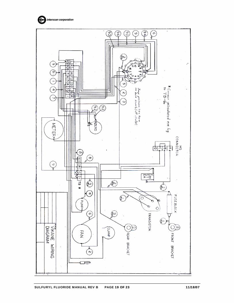
DIAGRAMS, SCHEMATICS & PARTS
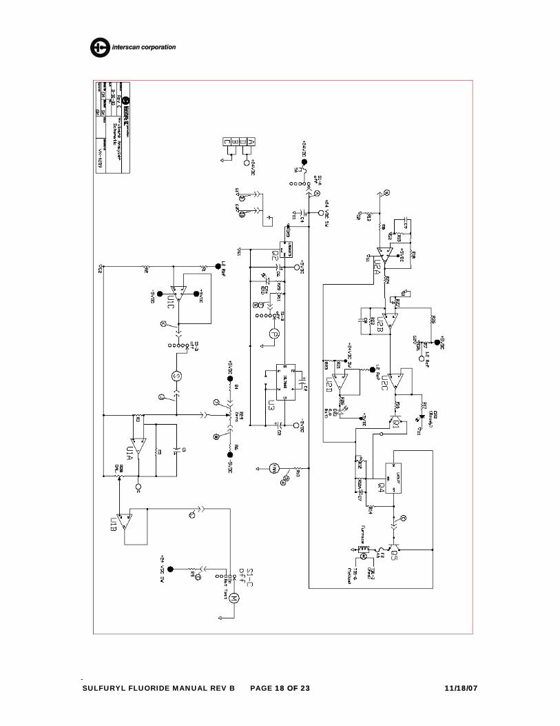
SULFURYL FLUORIDE MANUAL REV B PAGE 18 OF 23 11/18/07
SULFURYL FLUORIDE MANUAL REV B PAGE 19 OF 23 11/18/07

SULFURYL FLUORIDE MANUAL REV B PAGE 20 OF 23 11/18/07
Parts List…Interscan Model GF1900 RESISTORS R1 6192F R14 2430F R2 4992F R15 1001F R3 49R9F R16 20KΩ R4 2492F R17 51Ω R5 4992F R18 1003F R6 2492F R19 5.1KΩ R7 27KΩ R20 1.2KΩ R8 1001F R21 1273F R9 2552F R22 10MΩ R10 47Ω, 1W R23 7501F
R11 56Ω R24 100Ω R12 4021F R25 1.2KΩ R13 100KΩ R26 4991F RESISTORS, VARIABLE R12 50kΩ, 3262X-1-503/BOURNS R27 20KΩ, 3262X-1-203/BOURNS R28 10KΩ, 3250w-1-103/BOURNS R29 ` 50KΩ, 3590S-2-503/BOURNS
CAPACITORS C1 47μF, TANTALUM, 6VDC C2, C3, C6 10μF, TANTALUM, 25VDC C4 6.8μF, TANATALUM C8 _________________________ C5 1000μF, ELECTROLYTIC
SULFURYL FLUORIDE MANUAL REV B PAGE 21 OF 23 11/18/07
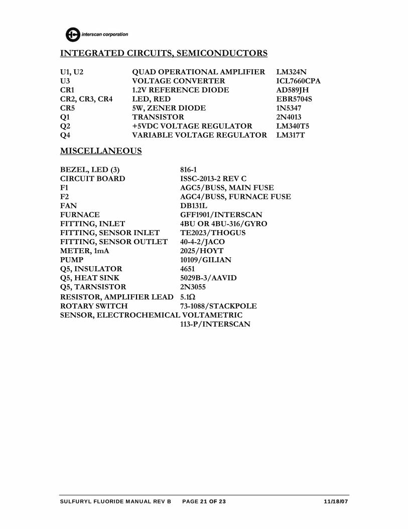
INTEGRATED CIRCUITS, SEMICONDUCTORS U1, U2 QUAD OPERATIONAL AMPLIFIER LM324N U3 VOLTAGE CONVERTER ICL7660CPA CR1 1.2V REFERENCE DIODE AD589JH CR2, CR3, CR4 LED, RED EBR5704S CR5 5W, ZENER DIODE 1N5347 Q1 TRANSISTOR 2N4013 Q2 +5VDC VOLTAGE REGULATOR LM340T5 Q4 VARIABLE VOLTAGE REGULATOR LM317T
MISCELLANEOUS BEZEL, LED (3) 816-1 CIRCUIT BOARD ISSC-2013-2 REV C F1 AGC5/BUSS, MAIN FUSE F2 AGC4/BUSS, FURNACE FUSE FAN DB131L FURNACE GFF1901/INTERSCAN FITTING, INLET 4BU OR 4BU-316/GYRO FITTING, SENSOR INLET TE2023/THOGUS FITTING, SENSOR OUTLET 40-4-2/JACO METER, 1mA 2025/HOYT PUMP 10109/GILIAN Q5, INSULATOR 4651 Q5, HEAT SINK 5029B-3/AAVID Q5, TARNSISTOR 2N3055 RESISTOR, AMPLIFIER LEAD 5.1Ω ROTARY SWITCH 73-1088/STACKPOLE SENSOR, ELECTROCHEMICAL VOLTAMETRIC 113-P/INTERSCAN
SULFURYL FLUORIDE MANUAL REV B PAGE 22 OF 23 11/18/07
SULFURYL FLUORIDE MANUAL REV B PAGE 23 OF 23 11/18/07
RETURN AUTHORIZATION All returns for repair require a RETURN AUTHORIZATION
NUMBER issued by the INTERSCAN Service Department upon request. This is done primarily to cause the user to contact the factory directly, as a high percentage of service problems can be resolved over the telephone, avoiding the need for returning the instrument or part. In other cases, the Service Department may ask for return of the circuit board only. The user is advised to consult the "TROUBLESHOOTING" section of the manual prior to contacting the factory. Instructions are simple, and no electronic repair background is necessary. This will avoid erroneous conclusions by the user as to the problem before contacting the factory. Should return of the instrument or part be advised by the Service Department, the "RETURN AUTHORIZATION NUMBER" will expedite prompt return of the repaired unit. For service information please contact: INTERSCAN CORPORATION Service Department (818) 882-2331 (800) 458-6153 (USA & CANADA) FAX: (818) 341-0642