GEZE APOLL - GERBANG CEMERLANG :: HOME capacity (kg) GEZE Apoll Rollers Permissible door weight...
38
GEZE APOLL
Transcript of GEZE APOLL - GERBANG CEMERLANG :: HOME capacity (kg) GEZE Apoll Rollers Permissible door weight...

GEZE APOLL

Subject to change without notice Contents 12.94
Contents
Page
Sliding Door Gear Product information 155
APOLL/Sliding doors 1-55APOLL/Components 6-17APOLL/End-folding doors 18-25APOLL/Centre-folding doors 26-31APOLL/Accessories for end-folding and centre-folding doors 32-35
Roller-GuidedSliding Door Gear

1Subject to change without notice Product information 12.94
Product information for Sliding Door Gear
In accordance with the definition ofthe liability of manufacturers for theirproducts set out in paragraph 4 of the „Produkthaftungsgesetz“(German manufacturer´s liability law),the following information on slidingdoor gear should be observed.Failure to do so absolves themanufacturer from liability.
Product information and use inaccordance with intended purposeSliding door gear, according to thisdefinition, are fittings for doors andother pushable elements, henceforthcalled objects, which are not normallymoved faster than walking pace.Sliding door gear is used in verticallyfitted doors made of wood, plastic,glass, aluminium or steel andappropriate combinations of thesematerials. A floor guide is provided at the lower horizontal edge of the door. Special versions of products must be specified for damp rooms,direct exposure to the elements,exposure to cross winds, for installation near the sea and in highly corrosive conditions.Correct installation by qualifiedpersonnel is a particularly importantaspect of use for intended purpose. The fitting must be firmly attached tothe object at the points provided for the purpose. The object must besufficiently rigid at all of these points.The function of the gear must not behindered or altered by installation. Abuffer must be used in order to limit the displacement path.
MisuseMisuse - in other words use in a manner not in accordance with theintended purpose - can be said to occur in the following cases inparticular: – if the gear is used with a higher
max. load than specified in thecatalogue and in the other product documents,
– if incorrectly installed or attached,– if ambient temperatures are too
high or too low,– if particularly aggressive media
can affect the gear,– if subjected to inordinately great
pushing or pulling loads,
– if the position of the track deviates too greatly from the horizontal,
– if foreign bodies get into the track,– if the rollers are operated too fast,– if alterations are carried out
without the manufacturer´sauthorization,
– if obstacles are placed in the opening or between the door or the object thereby preventing intended use,
– if additional loads act upon the door or object,
– if someone is trapped between the door and the door frame while the door is being pushed or closed, or if a person or part of the body is in this area.
Product performanceIn cases where the performance of theproduct is not specifically described inthe catalogues, brochures, instructionsetc., special requirements must bediscussed with and agreed by themanufacturer. Our regulations, whichaffect the composition of the sliding door gear, are binding.
Product maintenanceComponents of sliding door gear which are relevant to safety must beregularly inspected for proper fixing and signs of wear. Fixing screws are to be retightened and faulty compo-nents must be replaced. In addition, the following maintenance work must be carried out at least once a year:– All moving parts are to be tested
for free movement.– In the case of running carriages
with metal rollers, the moving partsmust be greased (type of grease to be used on request). Plastic rollersmust not be greased.
– Only use cleaning agents which do not impair the anti-corrosionprotection of the gear.
– Faulty sliding door gears must bereplaced.
– Adjustment work on the gears and the replacement of the same must be carried out by qualifiedpersonnel.
Duty of information and instructionThe following sources of information are available to planners, specialistdealers, administrative personnel,building contractors and users by way of fulfillment of the duty of informationand instruction: – catalogues, brochures– descriptions of tender,
descriptions of offer– mounting drawings, installation
drawings (standard drawings)– maintenance and operating
instructions.In order to ensure correct use, proper functioning and maintenance and care of sliding door gear, – architects and planners must
request and apply the necessaryproduct information,
– specialist dealers must take accountof the product information and notesin the price list, and in particular mustrequest all necessary instructions and pass these on to the installationpersonnel,
– installation personnel must takeaccount of all product information,and in particular must requestoperating and maintenanceinstructions and pass these on to the ordering party and the user.
Application for similar fittingsSliding gear with horizontally installedobjects, e.g., drawer guides or gear with vertical runner tracks must behandled according to their respectivecharacteristics with the respect toproduct information, use for intendedpurpose, misuse, product performance,product maintenance and servicing, and duty of information and instruction.

Load-bearing capacity (kg)GEZE Apoll Rollers Permissible door weight Roller load
Number Material sliding doors conveyors*
1Subject to change without notice GEZE APOLL 12.94
GEZE APOLL for Sliding DoorsSizes 0,1,2
Fig. 1 (Size shown 0)
Product features� Enclosed tubular track� Prismatic troughs� Tempered rollers with ball bearings� Movable hangers� 3 sizes
Range of applications� For all sliding doors� For all door materials� For side and soffit-fixing� For conveying and shifting systems� As mounting aids for trade and
industrial applications� For heavy loads, see table
Load-bearing capacity of track with 700 mm bracket spacing:Size 0 150 kg/mSize 1 350 kg/mSize 2 600 kg/m
Standard version/DeliveryGalvanized steel track, othercomponents galvanized
Fig. 2
steel 75 50single plastic 50 25Size 0
steel 150 100double plastic 100 50
steel 175 100single plastic 100 50Size 1
steel 350 200double plastic 200 100
steel 300 200single – – –Size 2
steel 600 300double – – –
*) Central suspended load
Size 0 Size 1 Size 2

2GEZE APOLL 12.94 Subject to change without notice
GEZE APOLL for Sliding DoorsApplication methods
When installing a sliding door, it is essential that stability and static and dynamic equilibrium are assured. The height-to-width ratio, and the resultingdifferent hanging points and fittings, such as door plates or edge-fixing hangers, is therefore decisive.
At a width-to-height ratio greater than 1,it is recommended to move the hangingpoint 0.2 x W towards the middle of thedoor (fig. 1).
At a width-to-height ratio less than 1, it is best to select edge-fixing hangers, -41, especially for very narrow doors (fig. 2).
With 2-leaf or multi-leaf door units,edge-fixing hangers, -42, which preventthe rollers from colliding, should be used(fig. 3).
The door stop -3 (fig. 5) is not intendedfor door stopping, but only as amounting aid and safety device wheninstalling the sliding door. When the door is in service a wall-fixed door stop,-66, must be positioned at the centre of gravity of the door to stop it. Twowall-fixed stops, -66, are also possible(fig. 4).
Door stops centered or at 2 points.
The flat-plate guide roller, -50, can beused for all door guides, irrespective ofwhich overhead hanger is selected.However, an edge-fixing guide roller, -51, -52, will be stronger (fig. 6).
With straight-in opening sliding doorsthe position of the floor guides isindependent of the fixing point of theoverhead hangers.
Fig. 3
Centre of gravity
Approx. every 70 cm
fig. 1 fig. 4
fig. 3 fig. 6
fig. 2
fig. 5

3Subject to change without notice GEZE APOLL 12.94
GEZE APOLL for Sliding DoorsInstallation optionsUnless otherwise indicated, the dimensions given in all the following tables on pages 3-35 are in millimetres.
Fig. 5
Side and soffit-fixing with bracket,door with door plate, see fig. 4
Size 0 Size 1 Size 2a4 41 52,5 70a5 20,5 26,5 35b1 100 135 170b2 70 91 114d 9 13 15d1 6,4 9 11e 32 42 56g1 89-112 116-139 149-177h2 41,5 53 71h3 side-fixing 15 18 24,5h3 soffit-fixing 29 38 48,5h4 43 55,5 72,5k Ø 22 Ø 24 Ø 30l 45 65 85l1 45 65 95m 80 114 140m1 M 10 M 12 M16p 22 30 40t 5 6 8u 110 180 220v 20 20 30w 35 45 53
Side and soffit-fixing with console,door with edge-fixing, see fig. 5
Size 0 Size 1 Size 2a1 side-fixing 45 64 90a1 soffit-fixing 45 49 80a2 20,5 26,5 35a3 50 65 85a6 15 24 40b 22-37 30-46 44-60 50-75c1 max. 14 max. 20 max. 30d2 11 13 17e 32 42 56f1 22,5 25 40g side-fixing 152-190 190-227 255-306g soffit-fixing 152-190 205-242 265-316h1 side-fixing 62-78 69-97 105-135h1 soffit-fixing 62-78 84-112 115-145k1 Ø 22 Ø 30 Ø 35l3 60 80 100m1 M 10 M 12 M 16u1 80 128 160
115u2 80 73 80
60w1 35 35 48
Fig. 4
0-101-102-10
0-311-312-31
0-401-402-40
0-11-12-1
0-111-112-11
0-11-12-1
0-501-502-50
1-542-54
1-542-54
0-201-202-20
0-301-302-30
0-141-142-14
0-31-32-3
1-662-66
0-431-432-43
0-201-202-20
0-141-142-14
0-31-32-3

4GEZE APOLL 12.94 Subject to change without notice
GEZE APOLL for Sliding DoorsInstallation options
Fig. 7
Fig. 7a
Side and soffit-fixing for doubleconsole, see fig. 6
Size 0 Size 1 Size 2
a2 20,5 26,5 35c max.69 max.85 max.130f 22,5 32 45g2 92-115 120-143,5 155-183g3 side-fixing 55 67,5 94,5g3 soffit-fixing 54,5 74,5 99,5h2 41,5 53 71h5 22,5 24 40
Joint bracketsee fig. 7
Size 0 Size 1 Size 2
l2 90 130 180
Welding bracketsee fig. 7a
Size 0 Size 1 Size 2
l 45 65 85
Fig. 6
0-221-222-22
0-141-142-14
0-221-222-22
0-141-142-14
0-121-122-12
0-131-132-13
On soft mounting surfaces bolt in steel plate

5Subject to change without notice GEZE APOLL 12.94
GEZE APOLL for Sliding DoorsInstallation options
Side and soffit-fixing with bracket,door with edge-fixing hanger, see fig. 8
Size 0 Size 1 Size 2a4 41 52,5 70a5 20,5 26,5 35b1 100 135 170b2 70 91 114d 9 13 15d1 6,4 9 11e 32 42 56g1 89-112 116-139 149-177h2 41,5 53 71h3 side-fixing 15 18 24,5h3 soffit-fixing 29 38 48,5h4 43 55,5 72,5k Ø 22 Ø 24 Ø 30l 45 65 85l1 45 65 95m 80 114 140m1 M 10 M 12 M16n 60 90 –p 22 30 –t 5 6 –u 110 180 –v 20 20 30w 35 45 –
Side and soffit-fixing with console,door with edge-fixing hanger, see fig. 9
Size 0 Size 1 Size 2a1 side-fixing 45 64 90a1 soffit-fixing 45 49 80a2 20,5 26,5 35a3 50 65 85a6 15 24 40c 14 20 30c1 14 20 30d2 11 13 17e 32 42 56f1 22,5 25 40g side-fixing 146-186 180-231 248-306g soffit-fixing 146-186 195-246 258-316h1 side-fixing 62-78 69-97 105-135h1 soffit-fixing 62-78 84-112 115-145k1 Ø 22 Ø 24 Ø 30l 45 65 85m1 M 10 M 12 M 16n1 18 20 30p 22 30 40t 5 6 8u 110 180 220w 35 45 53
Fig. 8
Fig. 9
0-311-312-31
0-521-522-52
1-542-54
0-421-422-42
0-101-102-10
0-11-12-1
0-111-112-11
0-11-12-1
0-201-202-20
0-141-142-140-30
1-302-30
0-201-202-20
0-141-142-14
0-411-412-41
0-511-512-51

6GEZE APOLL 12.94 Subject to change without notice
GEZE APOLL for Sliding DoorsTracks
Fig. 2
Track, see fig. 2
Size 0 Size 1 Size 2
Id. No. (6 m) 025769 018015 018014
Des. 0-1 1-1 2-1b 33 43 57h 39 51 67s 2 2,5 3,5Wxcm3 2,30 4,63 10,62e cm 2,16 2,85 3,73kg/m 1,9 2,02 5,72Load capacity per mwith 700 mm bracketspacing 150 kg 350 kg 600 kg
Fig. 3
Track curve, see fig. 3
Size 0 Size 1 Size 2
Id. No. 054769 054771 054773
Des. 0-2 1-2 2-2a 200 200 300r 700 800 1000s 2 2,5 3,5kg (weight) 2,85 4,53 12,4Straight length 1500 1660 2170

Size 0 Size 1 Size 2
7Subject to change without notice GEZE APOLL 12.94
GEZE APOLL for Sliding DoorsBrackets
Fig. 4
Fig. 5
Fig. 6
Side-fixing bracket, see fig. 4
Size 0 Size 1 Size 2
Id. No. 020701 012686 011554
Des. 0-10 1-10 2-10b 41 52,5 70h 80 100,5 135l 45 65 95s 2 2,5 3,5n 15 18 24,5m 20 23 29,5o 10 13 19,5k 25 40 60d 9 13 15e 6,4 9 11kg (weight) 0,3 0,6 1,4
Soffit-fixing bracket, see fig. 5
Id. No. 023286 012691 012119
Des. 0-11 1-11 2-11b 100 135 170h 50,5 66 86,5l 45 65 85o 45 60 90s 3,5 4 6n 70 91 114m – 10 10k 25 40 60d Ø 9 13 15e 6,4 9 11kg (weight) 0,3 0,6 1,4
Joint bracket, see fig. 6
Size 0 Size 1 Size 2
Id. No. 024004 012694 012306
Des. 0-12 1-12 2-12b 41 53,5 70h 47 60,5 80,5l 90 130 180s 3,5 4 6kg (weight) 0,4 0,9 2,1
Des. 0-13 1-13 2-13b 41 52,5 70h 47 60,5 80,5l 45 65 85s 3,5 4 6kg (weight) 0,2 0,5 1
8GEZE APOLL 12.94 Subject to change without notice
GEZE APOLL for Sliding DoorsBrackets
Fig. 7
Welding bracket, see fig. 7
Size 0 Size 1 Size 2
Id. No. 024093 012697 06965
Fig. 8
Bracket for vertical/lateral adjustment,see fig. 8
Size 0 Size 1 Size 2
Id. No. 024126 013097 007197
Des. 0-13 1-13 2-13b 41 52,5 70h 50,5 64,5 86l 45 65 85s 3,5 4 6d M 10 M 12 M 16kg (weight) 0,2 0,5 1

Subject to change without notice GEZE APOLL 12.94
Fig. 10
Side-fixing Soffit-fixing
Adjustment range Adjustment range
h2h1
h1 h2
9
GEZE APOLL for Sliding DoorsConsoles for vertical and lateral adjustmentwith bracket for vertical and lateral adjustment: 0–14
1–142-14
Single console for lateral and verticaladjustment, see fig. 9
Size 0 Size 1 Size 2
Id. No. 024325 013772 007205
Des. 0-20 1-20 2-20h1 62-78 69-97 105-135h2 62-78 84-112 115-145h3 48,5 54,5h4 48,5 68,5a 45 50 80b 55 70 100l 45 64 90n 15 24 40d 11 13 17e 11 9 11g 50 70 80m M 10 M 12 M 16f 20,5 26,5 35Adjustmentrange c 14 20 30
kg (weight) 0,3 0,5 1,3
Size 0 Size 1 Size 2
Id. No. 024402 013997 007261
Des. 0-21 1-21 2-21h1 62-78 69-97 105-135h2 62-78 84-112 115-145a 45 50 80b 110 138 90l 45 64 200n 15 24 40d 11 13 17e 11 9 11g 50 70 80m M 10 M 12 M 16f 20,5 26,5 130Adjustmentrange c 28 31,5 60
kg (weight) 0,4 0,8 2,5
Double console for lateral and verticaladjustment, see fig. 10
Fig. 9
Side-fixing Soffit-fixing

10GEZE APOLL 12.94 Subject to change without notice
GEZE APOLL for Sliding DoorsConsoles for vertical and lateral adjustmentwith bracket for vertical and lateral adjustment: 0–14
1–142-14
Single console for lateral adjustment,see fig. 11
Size 0 Size 1 Size 2
Id. No. 051857 051858 051859
Des. 0-23 1-23 2-23a 45 50 80l 45 64 90b 55 70 100n 15 24 40d 11 13 17e 11 9 11f 20,5 26,5 35m M 10 M 12 M 16Adjustmentrange 14 20 30
kg (weight) 0,3 0,5 1,3
Double console for lateral adjustment,see fig. 12
Size 0 Size 1 Size 2
Id. No. 024582 014048 007264
Des. 0-22 1-22 2-22a 45 50 80l 45 64 80b 110 138 200n 15 24 40d 11 13 17e 11 9 11f 20,5 26,5 35c 69 85 130m M 10 M 12 M 16Adjustmentrange 28 31,5 60
kg (weight) 0,4 0,8 2,5
Fig. 12
Side-fixing Soffit-fixing
Adjustment range Adjustment range
Fig. 11
Side-fixing Soffit-fixing
Adjustment rangeAdjustment range

11Subject to change without notice GEZE APOLL 12.94
GEZE APOLL for Sliding DoorsRollers
Single roller, steel or plastic*,see fig. 13
Size 0 Size 1 Size 2
Id. No. 016264 012468 008426Id. No.* 054045 054050 –
Id. No. 017274 012651 009484Id. No.* 054046 054051 –
Des. 0-30 1-30 2-30Des.* 0-36* 1-36* –a 50 65 85b 35 48 68h 58 80 104n 13 21 25e 32 42 56d M 10 M 12 M 16h1 60-83 78-101 101-129kg (weight) 0,2 0,6 1,4Max. load 50 kg 100 kg 200 kgMax. load.* 25 kg 50 kg –
Double roller, steel or plastic*see fig. 14
Size 0 Size 1 Size 2Des. 0-31 1-31 2-3Des.* 0-37* 1-37* –a 50 65 85b 35 48 68l 100 150 190m 80 114 140h 32 42 56c 26 37 48e 32 42 56d M 10 M 12 M 16n 13 20 25h1 60-83 78-101 101-129kg (weight) 0,5 1,2 2,7Max. load. 100 kg 200 kg 300 kgMax. load.* 50 kg 100 kg –
Fig. 13
Fig. 14

Single roller with pivot bearing, see fig. 15
12GEZE APOLL 12.94 Subject to change without notice
GEZE APOLL for Sliding DoorsRollers with pivot bearing
Size 0 Size 1 Size 2
Id. No. 050996 051021 049961
Des. 0-32 1-32 2-32a 50 65 85b 35 48 68h 58 80 104n 13 21 25e 32 42 56d M 10 M 12 M 16h1 66-83 83-101 106-129kg (weight) 0,27 0,68 1,5Max. load 50 kg 100 kg 200 kg
Double roller with pivot bearing, see fig. 16
Size 0 Size 1 Size 2
Id. No. 050997 049950 049962
Des. 0-33 1-33 2-33a 50 65 85b 35 48 68l 100 150 190m 80 114 140h 32 42 56c 26 37 48e 32 42 56d M 10 M 12 M 16n 13 20 25h1 66-83 83-101 106-129kg (weight) 0,57 1,28 2,8Max. load 100 kg 200 kg 300 kg
Fig. 15
Fig. 16

Size 0 St. 1 St. 2
13Subject to change without notice GEZE APOLL 12.94
GEZE APOLL for Sliding DoorsDoor plates and edge-fixing hangers
Door plate, see fig. 17
Id. No. 018431 012658 010890
Des. 0-40 1-40 2-40l 110 180 220a 22 30 40s 5 6 8d M 10 M 12 M 16e 6,4 8,4 8,4No. of fixing holes 4 4 6kg (weight) 0,1 0,2 0,5
Double-sided hanger, see fig. 18
Size 0 Size 1 Size 2
Id. No. 019138012947012946051318
Des. 0-43 1-43/1 1-43/2 2-43a 60 80 80 100b 22-37 30-46 44-60 50-75l 80 128 115 160c 80 73 60 80d M 10 M 12 M 12 M 16e 6,5 8,5 8,5 8,5kg (weight) 0,2 0,6 0,6 1,13
Edge-fixing hangerPivot point 18, 20, 30 mm, see fig. 19
Size 0 Size 1 Size 2
Id. No. 018801 012661 011094
Des. 0-41 1-41 2-41l 110 180 220a 22 30 40s 5 6 8n 18 20 30d M 10 M 12 M 16e 6,4 8,4 8,4No. of fixing holes 4 6 8kg (weight) 0,2 0,5 1
Edge-fixing hangerPivot point 60, 90, 100 mm, see fig. 20
Size 0 Size 1 Size 2
Id. No. 019019 012663 011133
Des. 0-42 1-42 2-42l 110 180 220a 22 30 40s 5 6 8n 18 20 100d M 10 M 12 M 16e 6,4 8,4 8,4No. of fixing holes 4 6 8kg (weight) 0,2 0,5 1
Fig. 17
Fig. 18
Fig. 19 Fig. 20

Id. No. 020404 012670 011354
14GEZE APOLL 12.94 Subject to change without notice
GEZE APOLL for Sliding DoorsFloor guide rollers and floor channel
Flat-plate guide roller,see fig. 21
Size 0 Size 1 Size 2
Id. No. 019884 012665 011139
Des. 0-50 1-50 2-50l 110 180 220a 22 30 40s 5 6 8d Ø 15,5 Ø 15,5 Ø 22e 6,4 8,4 8,4No. of fixing holes 4 4 6kg (weight) 0,11 0,3 0,5
Floor guide rollerPivot point 18, 20, 30 mm, see fig. 23
Size 0 Size 1 Size 2
Des. 0-51 1-51 2-51l 110 180 220a 22 30 40s 5 6 8n 18 20 30d Ø 15,5 Ø 15,5 Ø 22e 6,4 8,4 8,4No. of fixing holes 4 6 8kg (weight) 0,2 0,5 1
Floor guide rollerPivot point 16, 90, 100 mm, see fig. 24
Size 0 Size 1 Size 2
Id. No. 020522 012672 011514
Des. 0-52 1-52 2-52l 110 180 220a 22 30 40s 5 6 8n 60 90 100d Ø 15,5 Ø 15,5 Ø 22e 6,4 8,4 8,4No. of fixing holes 4 6 8kg (weight) 0,2 0,5 1
Size 1 Size 2
Id. No. (6 m) 051649 051654
Des. 1-54 2-54b 20 30h 20 30s 1,5 2,5kg/m 0,5 1,95
Floor channel, see fig. 22 Fig. 21 Fig. 22
Fig. 23
Fig. 24
15Subject to change without notice GEZE APOLL 12.94
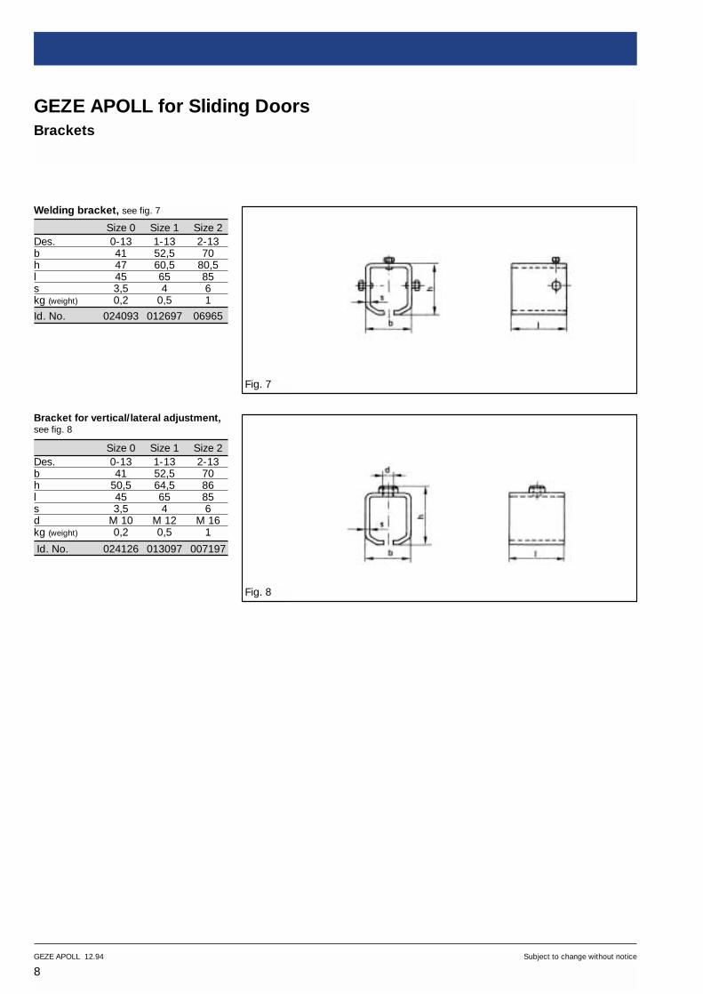
GEZE APOLL for Sliding DoorsCurved floor channel and accessories
Curved floor channel, see fig. 25
Size 0 Size 1 Size 2
Id. No. 054770 054772 054774
Des. 0-55 1-55 2-55a 200 200 300r 700 800 1000kg (weight) 0,90 1660 2170Straight length 1500 1660 2170
Door stop, see fig. 26
Size 0 Size 1 Size 2
Id. No. 024689 014440 007371
Des. 0-3 1-3 2-3b 30 35 50l 46 61 88h 28,5 39 51s 5 6 8n 6 9,5 12d Ø 14 Ø 18 Ø 30kg (weight) 0,1 0,3 0,8
Wall-fixed door stop, see fig. 27
Size 1 Size 2
Id. No. 000339 000342
Des. 1-66 2-66l 58 87b 26 36h 47 62d Ø 24 Ø 30n 10,5 12e 5 6kg (weight) 0,15 0,36
Fig. 25
Fig. 26
Fig. 27

Track, galvanized steel –1Bearing length 6 m 025769 018015 018014Cut to size 051506 051473 051472Track curve, galvanized steel
Radius 700 mm 0–2 054769 – –Curve 90° Radius 800 mm 1–2 – 054771 –
Radius 1000 mm 2–2 – – 054773Door stopBrackets and consoles
–3 024689 014440 007371
Side-fixing bracket –10 020701 012686 011554Soffit-fixing bracket –11 023286 012691 012119Joint bracket –12 024004 012694 012306Welding bracket –13 024093 012697 –Bracket for vertical and lateral adjustment
–14 024126 013097 007197
Single console for vertical and lateraladjustment
–20 024325 013772 –
Double console for vertical and lateraladjustment
–21 024402 013997 –
Single console for lateral adjustment –23 051857 051858 –Double console for lateral adjustment –22 024582 014048 –RollersSingle roller, steel –30 016268 012468 008426Single roller, plastic –36 054045 054050 –Double roller, steel –31 017274 012651 009484Double roller, plastic –37 054046 054051 –Single roller with pivot bearing *) –32 050996 051021 049961Double roller with pivot bearing *) –33 050997 049950 049962Pivot bearing –34 050998 049951 049963Door plates and edge-fixing hangersDoor plate –40 018431 012658 010890Edge-fixing Pivot point 18 mm 0–41 018801 – –hanger Pivot point 60 mm 0–42 019019 – –
Pivot point 20 mm 1–41 – 012661 –Pivot point 90 mm 1–42 – 012663 –
Double- for door thickness 22–37 mm 0–43 019138 – –sided for door thickness 30–46 mm 1–43/1 – 012947 –hanger for door thickness 44–60 mm 1–43/2 – 012946 –
for door thickness 50–75 mm 2–43 – – 051318
*) For sliding doors with curved track the rollers with pivot bearings should be used.0
Designation Fitting Id. No. no. Size 0 Size 1 Size 2
16GEZE APOLL 12.94 Subject to change without notice
GEZE APOLL for Sliding Doors
Specification text Text for placing orders
Tubular sliding door gearGEZE APOLL, size 0 (1, 2)Door weight ..... kg,No. of leaves .....,Leaf size .....,Track length .....,For side-fixing (or soffit-fixing)Double roller (or single roller)Door plate (edge-fixing hanger),floor guide, door stop and wall-fixeddoor stop
Note:The fittings are identified by numbers.The numbering is based on the following system:The number before the dash indicatesthe fitting size, the number after thedash the part number.That is to say, the number after the dash is the specific part identifier.The number before the dash changesaccording to the fitting size.
Examples:1–10 = GEZE APOLL size 1 –
Side-fixing bracket (no. 10)2–10 = GEZE APOLL size 2 –
Soffit-fixing bracket (no. 10)

17Subject to change without notice GEZE APOLL 12.94
GEZE APOLL for Sliding Doors
Designation Fitting Id. No. no. Size 0 Size 1 Size 2
Text for placing orders
Floor guideFlat-plate guide roller –50 019884 012665 011139Edge- Pivot point 18 mm 0–51 020404 – –fixing Pivot point 60 mm 0-52 020522 – –guide Pivot point 20 mm 1–51 – 012670 –roller Pivot point 90 mm 1–52 – 012672 –
Pivot point 30 mm 2-51 – – 011354Pivot point 100 mm 2-54 – – 011514
Floor channel, galvanized –54Bearing length 6 m 051649 051649 051654Cut to size 051650 051650 051655Curved floor channel
Radius 700 mm, blank 0–55 – 054772 –Curve 90°, Radius 800 mm, blank 1–55 – 054772 –
Radius 1000 mm, 2–55 – – 054774AccessoryWall-fixed door stop –66 000339 000339 000342

18GEZE APOLL 12.94 Subject to change without notice
GEZE APOLL for End-Folding DoorsSizes 0, 1, 2
Fig. 1The Leaves fold out only in one direction.Because of the eccentric load when thedoor is folded, a bottom guide roller isessential.
There are three common fitting options:Butt surface-mountedButt flush-mountedRebate-mounted.
The roller forms the pivot point on thefront face of every second leaf.
A full-height swing leaf is only possiblewith an odd number of leaves.
The most usual form of track mounting is by side- or soffit-fixing brackets.
Flush bolts should be fitted to the fold-out side.
The floor guide rollers should be fittedplumb underneath the pivot point of the rollers.
The best leaf widths are between 600 mm and 900 mm.
Use 3 hinges per leaf; for high leaves (≥ 280 cm) 4. Hinges with ball bearingsare recommended.
Starting with the end leaf hinged to thejamb, every second leaf is fitted with a rollerwith pivot bearing and edge-fitting hanger.
When choosing the track size and the roller,it should be noted that each roller has totake approximately the weight of twoleaves.
The use of double rollers is recommended.
In the fold area the brackets for trackmounting should be spaced at 350 mm(increased load-bearing).
Fig. 2

19Subject to change without notice GEZE APOLL 12.94
GEZE APOLL for End-Folding DoorsInstallation options
Fig. 3
Size 0 Size 1 Size 2A4 41 52,5 70A5 20,5 26,5 35b1 100 135 170b2 70 91 114e 32 42 56f 25 32 39,5g1 98-111,5 122,5-141,5 157-180,5h2 41,5 53 71h3 29 38 48,5h4 43,5 55,5 72,5h5 15 18 24,5
Size 0 Size 1 Size 2k Ø 22 Ø 24 Ø 30l 45 65 85l1 45 65 95m 80 114 140m1 M 10 M 12 M 16n 60 90 100p 22 30 40t 5 6 8u 110 180 220v 20 20 30w 35 45 53
0-101-102-10
0-331-332-33
0-11-12-1
0-441-442-44
0-531-532-53
0-421-422-42
0-521-522-52
1-542-54
0-351-352-35
0-111-112-11
0-651-65
0-11-12-1
a = Leaf width, leaf hinged to jamba1 = Leaf width, 2nd leafb = Leaf thicknessc = 1/2 hinges Ø +1d = b/2n = 60 with size 0z = No. of leaves
B = Clearance widtha = a1-(c+d+n)a1 = a+(c+d+n)
a1 = B+(c+d+n) ------------
2B = a+a1
a = Leaf widthb = Leaf thicknessc = 1/2 hinges ø +1f = 25 with size 0z = No. of leaves
B = Clearance widthB = a • z
B-zB-a
a =
z =
bauseits
Execution 2Execution 1

20GEZE APOLL 12.94 Subject to change without notice
GEZE APOLL for End-Folding DoorsInstallation options
Fig. 4
Size 0 Size 1 Size 2A1 45 49 80A2 22,5 25 40A3 50 65 85e 32 42 56g 156–186,5 202–251 265-319,5h1 61,5–78,5 84-112 114-145
Size 0 Size 1 Size 2k Ø 22 Ø 24 Ø 30l 45 65 85lm1 M 10 M 12 M 16n1 18 20 30p 22 30 40t 5 6 8u 110 180 220w 35 45 53x 14 20 30y 20,5 26,5 35
The gaps between the individual leaveswhen closed up are not taken intoaccount in calculating the leaf width.The leaf width should be adjustedaccording to choice of gap width.
0-321-322-32
0-141-142-14 0-20
1-202-20
0-411-412-41
0-511-512-51
Lockingdevice bycustomers
Execution 3
a = Leaf width, leaf hinged to jamb
a1 = a2 = a3 ... an Leaf width of following leaves
b = Leaf thicknessc = 1/2 hinges Ø +1d = b/2n1 = 18 with size 0z = No. of full leaves
B = Clearance widthB-a----a1
a1 = a+(c+d+n1)
a1 = B+(c+d+n1) ------------
z+1a = a1-(c+d+n1)a = B–(a1 • z)B = a+a1+a2+a3 ... anB = a+(a1 • z)
z =
21Subject to change without notice GEZE APOLL 12.94
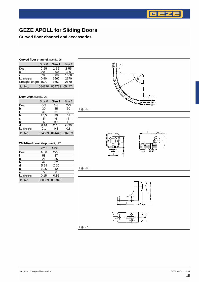
GEZE APOLL for End-Folding DoorsInstallation options
Fig. 5
Fig. 6
Installation options and examples forend-folding doorsFor end-folding doors there are threedifferent methods of fitting:
Butt surface-mountedButt surface-mounted, wall mountingwith side-fixing bracket, -10, track, -1,double roller with pivot bearing, -33,edge-fixing hanger for end-foldingdoors, -44, edge-fixing guide roller for end-folding doors, -53, and flushbolt, -65, floor channel, -54.
Fitting Size 0 Size 1 Size 2
Edge-fixing hangerfor end-foldingdoors 0–44 1–44 2-44Edge-fixing guide roller for end-folding doors 0–53 1–53 2-53Dimension f 25 32 39,5Dimension A5 20,5 26,5 35
Butt flush-mountedButt flush-mounted, soffit mounting withsoffit-fixing bracket, -11, track, -1,double roller with pivot bearing, -33,edge-fixing hanger, -41, floor guideroller, -51, and flush bolt, -65, floorchannel, -54.
Fitting Size 0 Size 1 Size 2
Edge-fixinghanger 0–41 1–41 2-41Floor guide 0–51 1–51 2-51Dimension n 18 20 30
a1=a2 = a3 = Leaf widthb = Leaf thicknessc = 1/2 hinge roller ø +1Only possible with odd number of leaves
Butt surface-mounted end-folding door
b/2 = Half door thicknessc = 1/2 hinge rollers ø +1a1+ a2 = Leaf widtha = Leaf width - (n+b/2+c)The leaf fitted at the blind frame is smaller than leaf a by the dimension (n+b/2+c)
Butt surface-mounted end-folding door
Removablecover

22GEZE APOLL 12.94 Subject to change without notice
GEZE APOLL for End-Folding DoorsInstallation options
Fig. 7
Rebate-mountedRebate-mounted, wall mounting withside-fixing bracket, -10, track, -1, double roller with pivot bearing, -33,edge-fixing hanger for end-foldingdoors, -44, edge-fixing guide roller for end-folding doors, -53, and flushbolt, -65, floor channel, -54.
Standard drawings for end-folding doorsSide- and soffit-fixingGEZE APOLL Size 0 No. 10620/0–10
Side-fixing with side-fixing bracketGEZE APOLL Size 1 No. 10621/0–10GEZE APOLL Size 2 No. 10622/0–10
Soffit-fixing with soffit-fixing bracketGEZE APOLL Size 1 No. 10621/0–11GEZE APOLL Size 2 No. 10622/0–11
Soffit-fixing with single console forvertical and lateral adjustmentGEZE APOLL Size 1 No. 10621/0–12GEZE APOLL Size 2 No. 10622/0–12
Fitting Size 0 Size 1 Size 2
Edge-fixing hangerfor end-foldingdoors 0–44 1–44 2-44Edge-fixing guideroller for end-folding doors 0–53 1–53 2-53Dimension f 25 32 39,5Dimension A5 20,5 26,5 35
a1 = a2 = a3 = Leaf widthb = Leaf thicknessc = 1/2 hinge roller ø +1Only possible with odd number of leaves
Rebate-mounted end-folding door

23Subject to change without notice GEZE APOLL 12.94
GEZE APOLL for End-Folding Doors
Designation Fitting Id. No.No. Size 0 Size 1 Size 2
Summary of fittings
1 track, length = twice leaf width+ 100 mm, cut to size, – 1 051506 051473 051472galvanized steel1 side-fixing bracketper 700 mm track length
–10 020701 012686 011554
1 double roller with pivot bearing –33 050997 049950 049962or 1 double roller with p. b., reduced version –35 054044 054052 054274or 1 single roller with pivot bearing –32 050996 051021 0499611 edge-fixing Pivot point 1 18 mm 0–41 018801 – –hanger Pivot point 160 mm 0–42 019019 – –
Pivot point 120 mm 1–41 – 012661 –Pivot point 190 mm 1–42 – 012663 –Pivot point 130 mm 2–41 – – 011094Pivot point 100 mm 2–42 – – 011133
or1 edge-fixing hanger for end-folding doors –44 050994 051012 0499521 edge-fixing Pivot point 118 mm 0–51 020404 – –guide roller Pivot point 160 mm 0–52 020522 – –
Pivot point 120 mm 1–51 – 012670 –Pivot point 190 mm 1–52 – 012672 –Pivot point 130 mm 2–51 – – 011354Pivot point 100 mm 2–52 – – 011514
or1 edge-fixing guide rollerfor end-folding doors
–53 050995 051015 049955
1 floor channelcut to size (length as track), –54 051650 051650 051655galvanized steel
82 x 35 mm 0–65 049974 – –1 flush bolt 120 x 45 mm 1–65 – 013474 0134743 to 4 hinges per leaf withball bearing rings supplied by customer
For soffit-fixing1 soffit-fixing bracketper 700 mm track length
–11 023286 012691 012119
or1 height-adjustable soffit-fixingper 700 mm track length, –20 024325 013772 007205consisting of single consoleand bracket -14 024126 013097 007197
Fittings as for 2-leaf unit,track and floor channelin length for 2-leaf widths,but hinges for 3 leaves
2-leaf end-folding door
3-leaf end-folding door

24GEZE APOLL 12.94 Subject to change without notice
GEZE APOLL for End-Folding Doors
Designation Fitting Id. No.No. Size 0 Size 1 Size 2
Summary of fittings
1 track, length = width of4 leaves + 100 mm, cut to size, – 1 051506 051473 051472galvanized steel1 side-fixing bracket per 700 mm track length –10 020701 012686 011554(in fold area per 350 mm)2 double rollers with pivot bearing –33 050997 049950 049962or2 double rollers with p. b., reduced version –35 054044 054052 054274or2 single rollers with pivot bearing –32 050996 051021 0499612 edge- Pivot point 118 mm 0–41 018801 – –fixing Pivot point 160 mm 0–42 019019 – –hangers Pivot point 20 mm 1–41 – 012661 –
Pivot point 190 mm 1–42 – 012663 –Pivot point 30 mm 2-41 – – 011094Pivot point 100 mm 2-42 – – 011133
or2 edge-fixing guide rollers for end-folding doors –44 050994 051012 0499522 edge- Pivot point 118 mm 0–51 020404 – –fixing Pivot point 160 mm 0–52 020522 – –guide Pivot point 120 mm 1–51 – 012665rollers Pivot point 190 mm 1–52 – 012670
Pivot point 30 mm 2-51 – – 011354Pivot point 100 mm 2-52 – – 011514
or2 edge-fixing guide rollersfor end-folding doors
–53 050995 051015 049955
1 floor channel,cut to size (length as track), –54 051650 051650 051655galvanized steel
82 x 35 mm 0–65 049974 – –2 flush bolts 120 x 45 mm 1–65 – 013474 0134743 to 4 hinges per leafwith ball bearing rings supplied by customer
For soffit-fixing1 soffit-fixing bracketper 700 mm track length
–11 023286 012691 012119
or1 height-adjustable soffit-fixing per 700 mm track length, –20 024325 013772 007205consisting of single consoleand bracket –14 024126 013097 007197
4-leaf end-folding door:All leaves fold to one side.

25Subject to change without notice GEZE APOLL 12.94
GEZE APOLL for End-Folding Doors
Designation Fitting Id. No.No. Size 0 Size 1 Size 2
Summary of fittings
As 2x2-leaf unit, but with2 edge-fixing Pivot point 160 mm 0–42 019019 – –hangers Pivot point 90 mm 1–42 – 012663 –2 edge-fixing Pivot point 60 mm 0–52 020522 – 011133guide rollers Pivot point 90 mm 1–52 – 012672 –
Pivot point 90 mm 1-52 – 012672 –Pivot point 100 mm 2-52 – – 011514
4-leaf end-folding door:2 leaves each folding to left andright respectively, track etc.
Text for placing orders
GEZE APOLL end-folding door gearSize ..., No. of leaves ...,Folding to right (left), side-fixing(or soffit-fixing) ..., block frame clearance height andwidth (H, W)

26GEZE APOLL 12.94 Subject to change without notice
GEZE APOLL for Centre-Folding DoorsSizes 0, 1, 2
Fig. 1Centre-folding, i. e. half inward and half outward.
Centre-folding doors start with a half leaf hinged to the jamb.
The rollers are fitted above the centre of the leaf.
The first roller is normally positioned at the first full leaf.
The track can be mounted with soffit- or side-fixing brackets.
On the underside of each leaf, on theside towards which the leaf folds, a flush bolt is fitted.
The floor guide should be arrangedplumb underneath the roller carriage.
The best leaf widths are between 600 mm and 900 mm.
Use 3 hinges per leaf; for high leaves (≥ 280 cm) 4. Hinges with ball bearingsare recommended.
The first full leaf is fitted with a roller;thereafter every second leaf.
When chossing the track size and theroller, it should be noted that each roller has to take approximately theweight of two leaves.
The use of double rollers isrecommended.
In the fold area the brackets for trackmounting should be spaced at 350 mm(increased load-bearing).
Fig. 2

27Subject to change without notice GEZE APOLL 12.94
GEZE APOLL for Centre-Folding DoorsInstallations options
Fig. 3
Size 0 Size 1 Size 2A4 41 52,5 70A5 20,5 26,5 35b1 100 135 170b2 70 91 114e 32 42 56g1 98–111,5 122,5–141,5 157–180,5h2 41,5 53 71h3 29 38 48,5h4 43,5 55,5 72,5h5 15 18 24,5
Size 0 Size 1 Size 2k Ø 22 Ø 24 Ø 30l 45 65 85l1 45 65 95m 80 114 140m1 M 10 M 12 M 16p 22 30 40t 5 6 8u 110 180 220v 20 20 30w 35 45 53
The gaps between the individual leaveswhen closed up are not taken intoaccount in calculating the leaf width.The leaf width should be adjustedaccording to choice of gap width.
0-331-332-33
0-401-402-40
0-101-102-10
0-11-12-1
0-501-502-50
0-651-65
1-542-54
0-351-352-35
0-401-402-40
0-111-112-11
0-501-502-50
a = First leaf
a1 = a2 = a3 ... an width
of following leaves
b = Leaf thicknessc = 1/2 hinges ø +1z = Number of full leaves
B = Clearance widtha = B - (z • a1)a = a1 : 2 - (c + (b:2)a1 = 2B + 2c + b : 1 + 2z
B = a+a1+a2+a3 ... an
B = a1 : 2 - (c + (b:2)) + a1 • zB = a + (z • a1)
by customers

28GEZE APOLL 12.94 Subject to change without notice
GEZE APOLL for Centre-Folding DoorsInstallation options
Standard drawings forcentre-folding doorsSide- and soffit-fixingGEZE APOLL Size 0 No. 10620/0–20
Side-fixingGEZE APOLL Size 1 No. 10621/0–20GEZE APOLL Size 2 No. 10622/0–20
Soffit-fixingGEZE APOLL Size 1 No. 10621/0–21GEZE APOLL Size 2 No. 10622/0–21Fig. 3
Size 0 Size 1 Size 2A1 45 50 80A2 22,5 25 40A3 50 65 85e 32 42 56g 156,5–186,5 219–242 277,5–345h1 61,5–78,5 84–112 115–145
Size 0 Size 1 Size 2k Ø 22 Ø 24 Ø 30l 45 65 85m1 M 10 M 12 M 16p 22 30 40t 5 6 8u 110 180 220w 35 45 53x 14 20 30y 20,5 26,5 35
0-321-322-32
0-141-142-14
0-201-202-20
0-401-402-40
0-501-502-50
Lockingdevice bycustomer

29Subject to change without notice GEZE APOLL 12.94
GEZE APOLL for Centre-Folding DoorsInstallation options
Fig. 5
Fig. 6
Fig. 7
Fitting Size 0 Size 1 Size 2
Door plate 0–40 1–40 2–40Floor guide roller 0–50 1–50 2–50
a1= a2 = a3···an width of followingleavesa = Width of first leaf hinged to blindframe
a= a1 - (c+b), c=1/2hinge rollers ø +12 2
Soffit-fixing, see fig. 6
With single console, -20, bracket forvertical and lateral adjustment, -14,track, -1, double roller with pivotbearing, -33, door plate, -40, flat-plateguide roller, -50, flush bolt, -65, floorchannel, -54.
With soffit-fixing bracket, -11, track, -1,double roller with pivot bearing, -33,door plate, -40, flat-plate guide roller,-50, flush bolt, -65, floor channel, -54.
Side-fixing, see fig. 7
With single console, -20, bracket forvertical and lateral adjustment, -14,track, -1, double roller with pivotbearing, -33, door plate, -40, flat-plateguide roller, -50, flush bolt, -65, floorchannel, - 54.
With side-fixing bracket, -10, track, -1,double roller with pivot bearing, -33,door plate, -40, flat-plate guide roller, -50, flush bolt, -65, floor channel, -54.

30GEZE APOLL 12.94 Subject to change without notice
GEZE APOLL for Centre-Folding Doors
Designation Fitting Id. No.No. Size 0 Size 1 Size 2
Summary of fittings
1 track,length = 1xleaf width + 100 mm, – 1 051506 051473 051472cut to size, galvanized steel1 soffit-fixing bracketper 700 mm track length
–11 023286 012691 012119
or1 single console for verticaland lateral adjustment
–20 024325 013772 007205
with 1 bracket for vertical and lateraladjustment per 700 mm track length
–14 024126 013097 007197
1 double roller with pivot bearing –33 050997 049950 049962or1 double roller with p. b., reduced version –35 054044 054052 –or1 single roller with pivot bearing –32 050996 051021 0499611 door plate –40 018431 012658 0108901 flat-plate guide roller –50 019884 012665 0111391 floor channel,galvanized steel, length as –54 051650 051650 051655track, cut to size2 flush bolts 82 x 35 mm 0–65 049974 – –
120 x 45 mm 1–65 – 013474 0134743 to 4 hinges per leafwith ball bearing rings supplied by customer
For side-fixing1 side-fixing bracketper 700 mm track length
–10 020701 012686 011554
1 tracklength = 3xleaf width + 100 mm – 1 051506 051473 051472cut to size, galvanized steel1 soffit-fixing bracket per700 mm track length –11 023286 012691 012119(in fold area per 350 mm)or1 single console for vertical and lateral adjustment
–20 024325 013772 –
with 1 bracket for vertical and lateral adjustment per 700 mm track length
–14 024126 013097 007197
2 double rollers with pivot bearing –33 050997 049950 049962or 2 double rollers with p.b., reduced version –35 054044 054052 –or 2 single rollers with pivot bearing –32 050996 051021 0499612 door plates –40 018431 012658 0108902 flat-plate guide rollers –50 019884 012665 0111391 floor channel,galvanized steel, length as track, –54 051650 051650 051655cut to size
21/2-leaf centre-folding door
31/2-leaf centre-folding door

31Subject to change without notice GEZE APOLL 12.94
GEZE APOLL for Centre-Folding Doors
Designation Fitting Id. No.No. Size 0 Size 1 Size 2
Summary of fittings
3 flush bolts 82 x 35 mm 0–65 049974 – –120 x 45 mm 1–65 – 013474 013474
3 to 4 hinges per leafwith ball bearing rings supplied by customer
For side-fixing1 side-fixing bracketper 700 mm track length –10 020701 012686 011554(in fold area per 350 mm)
41/2-leaf centre-folding door1 tracklength = 3xleaf width + 100 mm – 1 051506 051473 051472cut to size, galvanized steel1 soffit-fixing bracket per 700 mm track length –11 023286 012691 012119(in fold area per 350 mm)or1 single console for vertical and lateral adjustment
–20 024325 013772 –
with 1 bracket for vertical and lateraladjustment per 700 mm track lenght
–14 024126 013097 007197
2 double rollers with pivot bearing –33 050997 049950 049962or 2 double rollers with p.b., reduced version –35 054044 054052 –or 2 single rollers with pivot bearing –32 050996 051021 0499612 door plates –40 018431 012658 0108902 flat-plate guide rollers –50 019884 012665 0111391 floor channel,galvanized steel, length as track, –54 051650 051650 051655cut to size4 flush bolts 82 x 35 mm 0–65 049974 – –
120 x 45 mm 1–65 – 013474 0134743 to 4 hinges per leafwith ball bearing rings supplied by customer
For side-fixing1 side-fixing bracketper 700 mm track length –10 020701 012686 011554(in fold area per 350 mm)For 5-leaf and multi-leaf units,on request.
Text for placing orders
GEZE APOLL centre-folding door gearSize ..., No. of full leaves (+1/2 leaf perfolding side)Folding to right (left), block frame clearanceheight and width (H,W)Side-fixing (or soffit-fixing)

32GEZE APOLL 12.94 Subject to change without notice
GEZE APOLL for End-Folding and Centre-Folding DoorsAccessories
Single roller with pivot bearing, see fig. 1
Size 0 Size 1 Size 2
Id. No. 050996 051021 049961
Des. 0-32 1-32 2-32a 50 65 85b 35 48 68h 58 80 104n 13 21 25e 32 42 56d M 10 M 12 M 16h1 66-83 83-101 106-129kg (weight) 0,27 0,68 1,5Max. load 50 kg 100 kg 200 kg
Double roller with pivot bearing, see fig. 2
Size 0 Size 1 Size 2
Id. No. 050997 049950 049962
Des. 0-33 1-33 2-33a 50 65 85b 35 48 68l 100 150 190m 80 114 140h 32 42 56c 26 37 48e 32 42 56d M 10 M 12 M 16n 13 20 25h1 66-83 83-101 106-129kg (weight) 0,57 1,28 2,8Max. load 100 kg 200 kg 300 kg
Double roller with pivot bearing,reduced version, see fig. 4
Size 0 Size 1 Size 2
Id. No. 054044 054052 054274
Des. 0-35 1-35 2-35door thickness <40 <60 <80a 50 65 85b 35 48 68m 34 45 60h 58 80 104e 32 42 56d M 10 M 12 M 16n 13 20 25h1 66-83 78-101 101-129kg (weight) 0,35 0,9 2,1Max. load 100 kg 200 kg 300 kg
Pivot bearings, loose, see fig. 3
Size 0 Size 1 Size 2
Id. No. 050998 049951 049963
Des. 0-34 1-34 2-34a M 16x1,5 M 20x2 M 24x 2b 22 25 30h 66–83 83–101 106–129kg ( weight) 0,07 0,08 0,1
Fig. 1
Fig. 2
Fig. 3 Fig. 4

33Subject to change without notice GEZE APOLL 12.94
GEZE APOLL for End-Folding and Centre-Folding DoorsAccessories
Edge-fixing hangerPivot point 18, 20, 30 mm, see fig. 5
Size 0 Size 1 Size 2
Id. No. 018801 012661 011094
Des. 0–41 1–41 2-41l 110 180 220a 22 30 40s 5 6 8n 18 20 30d M 10 M 12 M 16e 6,4 8,4 8,4No. of fixing holes 4 6 8kg (weight) 0,2 0,5 1
Edge-fixing hangerPivot point 60, 90, 100 mm, see fig. 6
Size 0 Size 1 Size 2
Id. No. 019019 012663 011133
Des. 0–42 1–42 2-42l 110 180 220a 22 30 40s 5 6 8n 60 90 100d M 10 M 12 M 16e 6,4 8,4 8,4No. of fixing holes 4 6 8kg (weight) 0,2 0,5 1
Edge-fixing hanger for end-folding see fig. 7
Size 0 Size 1 Size 2
Id. No. 050994 051012 049952
Des. 0–44 1–44 2-44a 110 180 220b 147 225 280c 22 30 40s 5 6 8e Ø 6,4 Ø 8,4 Ø 8,4f 25 32 39,5l 110 180 220No. of fixing holes 4 6 8kg (weight) 0,25 0,6 1,3
Fig. 5
Fig. 6
Fig. 7

34GEZE APOLL 12.94 Subject to change without notice
GEZE APOLL for End-Folding and Centre-Folding DoorsAccessories
Door plate, see fig. 8
Size 0 Size 1 Size 2
Id. No. 018431 012658 010890
Des. 0–40 1–40 2–40l 110 180 220a 22 30 40s 5 6 8d M 10 M 12 M 16e 6,4 8,4 8,4No. of fixing holes 4 4 6kg (weight) 0,1 0,2 0,5
Fig. 8
Fig. 9
Fig. 10
Double-sided hanger,see fig. 9
Size 0 Size 1 Size 2
Id. No. 019138 012947 012946 051318
Des. 0-43 1-43/1 1-43/2 2-43a 60 80 80 100l 80 128 115 160c 80 73 60 80d M 10 M 12 M 12 M 16e 6,5 8,5 8,5 8,5b 22–37 30–46 44–60 50–75kg (weight) 0,2 0,6 0,6 1,13
Flat-plate guide roller,see fig. 10
Size 0 Size 1 Size 2
Id. No. 019884 012665 011139
Des. 0–50 1–50 2–50l 110 180 220a 22 30 40s 5 6 8d Ø 15,5 Ø 15,5 Ø 22e 6,4 8,4 8,4No. of fixing holes 4 4 6kg (weight) 0,11 0,3 0,5

35Subject to change without notice GEZE APOLL 12.94
GEZE APOLL for End-Folding and Centre-Folding DoorsAccessories
Fig. 11
Fig. 12 Fig. 13
Fig. 14
Edge-fixing guide roller for end-foldingdoors, see fig. 11
Size 0 Size 1 Size 2
Id. No. 050995 051015 049955
Des. 0–53 1–53 2-53a 110 180 220b 147 225 280c 22 30 40s 5 6 8e Ø 6,4 Ø 8,4 Ø 8,4f 25 32 39,5g Ø 15,5 Ø 15,5 Ø 22l 110 180 220kg (weight) 0,25 0,6 1,32
Floor guide rollerPivot point 18, 20, 30 mm, see fig. 12
Size 0 Size 1 Size 2
Id. No. 020404 012670 011354
Des. 0–51 1–51 2-51a 110 180 220c 22 30 40s 5 6 8n 18 20 30d Ø 15,5 Ø 15,5 Ø 22e 6,4 8,4 8,4No. of fixing holes 4 6 8kg (weight) 0,2 0,5 1
Floor guide rollerPivot point 60, 90, 100 mm, see fig. 13
Size 0 Size 1 Size 2
Id. No. 020522 012672 011514
Des. 0–52 1–52 2-52a 110 180 220c 22 30 40s 5 6 8n 60 90 100d Ø 15,5 Ø 15,5 Ø 22e 6,4 8,4 8,4No. of fixing holes 4 6 8kg (weight) 0,2 0,5 1
Flush bolt, see fig. 14
Size 0 Size 1
Id. No. 049974 013474
Des. 0–65 1–65a 82 120b 35 45c 13 36d 7 18kg (weight) 0,05 0,22