
Getting Started with OpenRoads Designer · 2019-09-10 · The theme of this workbook is modeled...
66
Practice Workbook NCDOT Quick Start for OpenRoads Designer CONNECT Edition NCDOT Roadway Design Unit About this Practice Workbook... ◼ This PDF file includes bookmarks providing an overview of the document. Click on the bookmark to quickly jump to any section in the file. You may have to turn on the bookmark function in your PDF viewer, such as Adobe Reader. ◼ The dataset used throughout this Quick Start guide uses English units. ◼ Each module in this Quick Start guide is self-contained. You can jump to any module and begin the exercises. ◼ This training uses the NCDOT_Roadway workspace and the Quick Start workset installed. It is very important that you select the Quick Start workset when working the exercises in this course. ◼ The theme of this workbook is modeled from the Bentley Institute and its Quick Start Guides. ◼ This workbook was written with the release of OpenRoads Designer 10.01.00.15 (Update 1). ◼ This workbook has been updated for OpenRoads Designer 10.07.00.56 (2019 Release 1 Update 7). Oak Thammavong | NCDOT Roadway Design Unit
Transcript of Getting Started with OpenRoads Designer · 2019-09-10 · The theme of this workbook is modeled...

Practice Workbook
NCDOT Quick Start for OpenRoads
Designer CONNECT Edition
NCDOT Roadway Design Unit
About this Practice Workbook...
◼ This PDF file includes bookmarks providing an overview of the document. Click on the bookmark to quickly jump to any section in the
file. You may have to turn on the bookmark function in your PDF viewer, such as Adobe Reader.
◼ The dataset used throughout this Quick Start guide uses English units.
◼ Each module in this Quick Start guide is self-contained. You can jump to any module and begin the exercises.
◼ This training uses the NCDOT_Roadway workspace and the Quick Start workset installed. It is very important that you select the Quick
Start workset when working the exercises in this course.
◼ The theme of this workbook is modeled from the Bentley Institute and its Quick Start Guides.
◼ This workbook was written with the release of OpenRoads Designer 10.01.00.15 (Update 1).
◼ This workbook has been updated for OpenRoads Designer 10.07.00.56 (2019 Release 1 Update 7).
Oak Thammavong | NCDOT Roadway Design Unit

Copyright © 2019 NCDOT Roadway Design DO NOT DISTRIBUTE - Printing for student use is permitted 2
Module 1: Overview and Terrain
Description
In this module you will review the OpenRoads Designer interface and import the existing ground terrain.
Objectives
◼ User Interface (Ribbon)
◼ Backstage Functionality
◼ Search Capability
◼ Bentley Connect Advisor
◼ Quick Access Toolbar
◼ Integration with GEOPAK

Copyright © 2019 NCDOT Roadway Design DO NOT DISTRIBUTE - Printing for student use is permitted 3
Start OpenRoads Designer and Select Workspace
1. Start the OpenRoads Designer software by double-clicking on the desktop icon.
2. Click the Start a Work Session arrow on the right side of the screen.
Copyright © 2019 NCDOT Roadway Design DO NOT DISTRIBUTE - Printing for student use is permitted 4
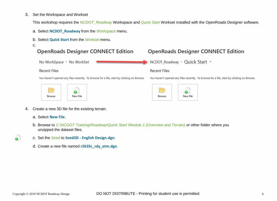
3. Set the Workspace and Workset
This workshop requires the NCDOT_Roadway Workspace and Quick Start Workset installed with the OpenRoads Designer software.
a. Select NCDOT_Roadway from the Workspace menu.
b. Select Quick Start from the Workset menu.
c.
4. Create a new 3D file for the existing terrain.
a. Select New File.
b. Browse to C:\NCDOT Training\Roadway\Quick Start \Module 1 (Overview and Terrain) or other folder where you
unzipped the dataset files.
c. Set the Seed to Seed3D ‐ English Design.dgn.
d. Create a new file named r2635c_rdy_etm.dgn.

Copyright © 2019 NCDOT Roadway DO NOT DISTRIBUTE - Printing for student use is permitted 5
Review the Interface
1. Select the OpenRoads Modeling workflow from the pick list in the upper left corner if it is not already active.
The ribbon menu changes to OpenRoads Modeling tools organized into similar categories called ribbon tabs.
◼ Home - Common tools such as attributes, Explorer, references, models, element selection, fences, and reports.
◼ Terrain - Element Selection and terrain modeling tools.
◼ Geometry - Element Selection, Civil AccuDraw, and geometry tools including Lines, Arcs, and Points.
◼ Site Layout – Import SITEOPS File, Parking, Pad, Pathway, Vertical Geometry, Grading Proposed
◼ Corridors - Element Selection, superelevation, and corridor modeling tools.
◼ Model Detailing - Element Selection, Civil Cells, and 3D (linear template, surface templates, etc.) tools.
◼ Drawing Production - Element Selection, notes, text, annotations, and plans production (cross section, plan, and
profile) tools.
◼ Drawing - Commonly used MicroStation drawing tools. To access the complete set of MicroStation tools change the active workflow
to Drawing, Modeling (3D only), or Visualization (3D only).
◼ View - Commonly used view control tools.
◼ NCDOT_Roadway- AutoTurn, Power Delete, Common Roadway Design Tools

Copyright © 2019 NCDOT Roadway Design DO NOT DISTRIBUTE - Printing for student use is permitted 6
2. Searching the ribbon.
When you are not sure where to find a tool on the ribbon interface, the Search Ribbon field in the upper right corner is your best friend.
a. Type Template in the search field.
The matches found in the ribbon menus appear. The search is across all ribbon
menus, not just the currently active ribbon.
b. Hover over Create Template.
The search results expand showing where this tool is located on the ribbon.
c. Select Create Template to start that tool.
Notice that the Create Template tool started but the ribbon menu did not change.
d. Close the Create Template dialog.
e. Type Template in the search field again.
f. Hover over Create Template to expand the search options.
g. Select OpenRoads Designer → Corridors → Create → Template.
The ribbon changes to the selected menu which contains the Create Template tool.
3. Auto hide ribbon.
a. Double click on any Ribbon Tab (such as Corridors) to set the ribbon menu in auto hide mode.
b. Double click a Ribbon Tab again disable auto hide mode.
4. Introduction to the Backstage.
a. Activate the Back Stage View by clicking File in the ribbon menu.
b. Select Settings.
c. Design File settings, preferences, customizations, etc. are found in the Backstage, keeping the ribbon menus
focused on the tools.
d. Click the Arrow in the upper left corner to return to the design canvas.
5. Use the Bentley CONNECT Advisor (upper right corner) to search for topics and Q&A’s in the Bentley Communities.
6. The Quick Access Toolbar (upper left corner) contains common tools found in most workflows and ribbon tabs.

Copyright © 2019 NCDOT Roadway DO NOT DISTRIBUTE - Printing for student use is permitted 7
Import Existing Ground Terrain from GEOPAK TIN
1. Select From File from the Terrain > Create tab on the OpenRoads Modeling workflow (ribbon).
2. Select r2635c_ph_tin_040927.tin from the Module 1 (Overview and Terrain) folder.
3. Set the Feature Definition to Terrain >
Existing > ET_Boundary-RDY.
This terrain could have originated in
ConceptStation, InRoads, GEOPAK, or
other applications.
4. Click Import.
5. Close the Import Terrain Model dialog.
6. Select Fit View to see the terrain model.
7. Select Save Settings.
HINT: The icon is found in the Quick
Access toolbar at the top of the screen.
8. Exit OpenRoads Designer.
The modules in this Quick Start guide are designed to be self contained. Please exit the software after each module and begin again with
the files included in the next module.

Copyright © 2019 NCDOT Roadway Design DO NOT DISTRIBUTE - Printing for student use is permitted 8
Module 2: Geometry
Description
In this module you will import and annotate geometry from GEOPAK (GPK) and inRoads (ALG).
Objectives
◼ Integration with GEOPAK and inRoads
◼ Attach Reference File
◼ Annotation Group
◼ Annotation Scale
◼ Civil Labels
◼ Feature Definitions

Copyright © 2019 NCDOT Roadway Design DO NOT DISTRIBUTE - Printing for student use is permitted 9
Attach Original Ground Terrain
1. Start the OpenRoads Designer software and ensure that the Workspace is set to NCDOT_Roadway and the Workset
is set to Quick Start.
2. Use the Browse button to open the file r2635c_rdy_alg.dgn from the Module 2 (Geometry and Annotation) folder.
3. Attach r2635c_rdy_etm.dgn as reference using a Coincident-World orientation.
HINT: Reference tools are on the Home ribbon tab.
4. Fit the view.
5. Set the original ground as the Active Terrain Model.
6. Select Save Settings.

Copyright © 2019 NCDOT Roadway Design DO NOT DISTRIBUTE - Printing for student use is permitted 10
Import Geometry
1. Import the geometry.
a. Select Import Geometry from the Geometry ribbon tab
b. Browse to and select the cmjobRDY.alg file.
c. Select the check box next to F_Prop CL to select all alignments, except for L.
d. Enable the Create Civil Rules option.
e. Click Import.
f. Repeat steps a thru e, with the exception of selecting the jobrdy.gpk and the alignments L/L(pro) only.
2. Assign Feature Definition to geometry.
a. Select All to add the geometry elements to a selection set.
b. From the Geometry > General Tools > Standards tab, select Set Feature
Definition.
c. Set the parameters and data point to update the feature definitions.
◼ Feature Type = Alignment
◼ Feature Definition = Alignment > ALG_Centerline-RDY.
d. Select None to clear the selection set.

Copyright © 2019 NCDOT Roadway Design DO NOT DISTRIBUTE - Printing for student use is permitted 11
Annotate Geometry
1. Zoom to where the first interchange is visible.
2. Annotate a single alignment.
a. Select Annotate Element from the Drawing Production ribbon tab Annotation tools group.
b. Select the L (mainline) centerline.
c. Reset to annotate the alignment.
3. Change the annotation scale.
a. Set the Annotation Scale on the Drawing ribbon tab to 1”=100’ to make the annotations larger.
4. Remove annotation from a single alignment.
a. Select Remove Element Annotations from the Drawing Production ribbon tab.
b. Select the L (mainline) centerline
c. Reset to clear the annotation.
5. Annotate multiple alignments.
a. Fit the view so all alignments are visible.
b. Select All to add the geometry elements to a selection set.
c. Select Annotate Element from the Drawing Production ribbon tab.
d. Data point to annotate the selected geometry.
6. Set the Annotation Scale on the Drawing ribbon tab to 1”=50’ to update all annotations to a 50 scale.

Copyright © 2019 NCDOT Roadway Design DO NOT DISTRIBUTE - Printing for student use is permitted 12
Civil Labels
1. Zoom to the beginning of Jenks Road (-Y11-). It is the first minor crossing
road after the first interchange.
2. Label begin construction limit.
a. Select Place Label from the Drawing Production ribbon tab Notes
tools group.
◼ Place a label with a leader
◼ Type = Cell
◼ Cell Name = _Lbl_Pln_Beg Const -Y- Line
◼ Dimension Style = _Lbl_Pln_Beg Const -Y- Line
Note: Dimension Style is automatically selected if the Cell Name is the same.
◼ Label Rotation = Horizontal
◼ Start At = Terminator
◼ Horizontal Attachment = Auto
◼ Enable Annotation Scale, Association, and Relative Association
b. Select the Y11 centerline.
c. Data point near the beginning of the alignment within the tangent section.
d. Place the label above the alignment.
3. Move and rotate (Drawing ribbon tab) the label and notice the stationing
dynamically updates.
Copyright © 2019 NCDOT Roadway Design DO NOT DISTRIBUTE - Printing for student use is permitted 13
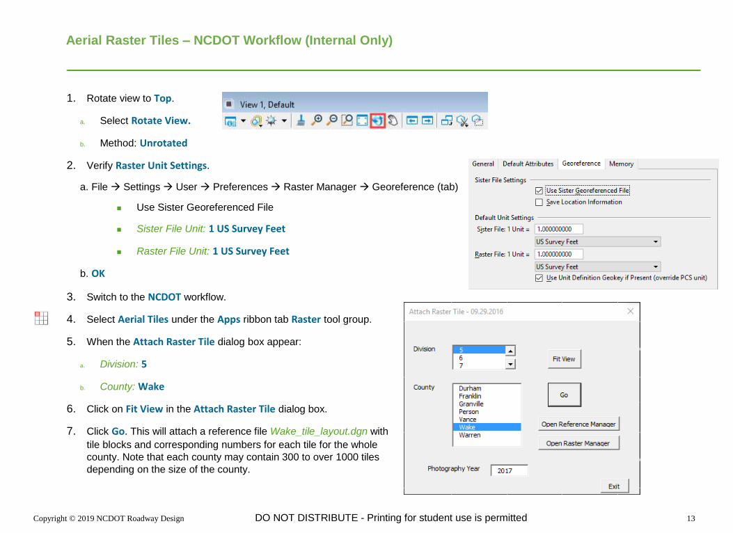
Aerial Raster Tiles – NCDOT Workflow (Internal Only)
1. Rotate view to Top.
a. Select Rotate View.
b. Method: Unrotated
2. Verify Raster Unit Settings.
a. File → Settings → User → Preferences → Raster Manager → Georeference (tab)
◼ Use Sister Georeferenced File
◼ Sister File Unit: 1 US Survey Feet
◼ Raster File Unit: 1 US Survey Feet
b. OK
3. Switch to the NCDOT workflow.
4. Select Aerial Tiles under the Apps ribbon tab Raster tool group.
5. When the Attach Raster Tile dialog box appear:
a. Division: 5
b. County: Wake
6. Click on Fit View in the Attach Raster Tile dialog box.
7. Click Go. This will attach a reference file Wake_tile_layout.dgn with
tile blocks and corresponding numbers for each tile for the whole
county. Note that each county may contain 300 to over 1000 tiles
depending on the size of the county.

Copyright © 2019 NCDOT Roadway Design DO NOT DISTRIBUTE - Printing for student use is permitted 14
8. Click on the number inside each block you wish to attach the raster tiles.
9. Once all desired raster tiles have been
attached, you can then detach the
Wake_tile_layout.dgn file through the Open
Reference Manager button in the Attach Raster
Tile dialog box.
10. Click on Open Raster Manager to verify each
raster tile (.sid file) has been attached properly.

Copyright © 2019 NCDOT Roadway Design DO NOT DISTRIBUTE - Printing for student use is permitted 15
11. As an option each tile or .sid file can be saved locally to the C:\ drive by right mouse click each .sid file in the Raster
Manager dialog box and then choose Save as.
a. Save as type: GEOTIFF (*.tif)
12. Exit OpenRoads Designer.
The modules in this Quick Start guide are designed to be self-contained. Please exit the software after each module and begin again
with the files included in the next module.

Copyright © 2019 NCDOT Roadway Design DO NOT DISTRIBUTE - Printing for student use is permitted 16
Module 3: Modeling
Description
In this module you will model a minor roadway and a temporary model of the bridge. You will also model a 7.25 mile long section of
roadway.
Objectives
◼ Drawing Scale across references
◼ General Modeling
◼ File Federation
◼ Integration with OpenBridge Modeler (OBM)
◼ Performance

Copyright © 2019 NCDOT Roadway Design DO NOT DISTRIBUTE - Printing for student use is permitted 17
Model Jenks Road (-Y11-)
1. Start the OpenRoads Designer software and ensure that the Workset is set to Quick Start.
2. Open the file r2635c_rdy_cmd_y11.dgn from the Module 3 (Corrido Modeling) folder.
3. Click in View 1 to make it the active view and model.
4. Use New Corridor from the Corridors ribbon tab to create a corridor along -Y11- from the beginning of alignment to
the bridge at approximately station 19+35 +/-.
◼ Feature Definition = Corridor > Design – A50 (set in the Tool Settings dialog)
◼ Profile = Active Profile
◼ Feature Name = Y11
◼ Template = Template > TMPLT-Shoulder Dual Lane Roadway (Alt + ↓ to open template library)
◼ Start Station = Beginning of Alignment (Alt to lock to beginning station)
◼ End Station = 19+35
◼ Drop Interval = 5
◼ Minimum Transition Before Drop = 0
◼ Minimum Transition After Drop = 0

Copyright © 2019 NCDOT Roadway Design DO NOT DISTRIBUTE - Printing for student use is permitted 18
5. Continue the corridor from the end of the bridge at approximately station 22+00 +/- to the end of the alignment.
◼ Template = Template > TMPLT-Shoulder Dual Lane Roadway
◼ Start Station = 22+00
◼ End Station = End of Alignment (Alt to lock to ending station)
◼ Drop Interval = 5
◼ Minimum Transition Before Drop = 0
◼ Minimum Transition After Drop = 0
6. Change corridor feature definition.
a. Select the corridor.
b. Open the corridor Properties.
c. Set the Feature Definition = Corridor > Final
Notice the cross section drop interval tightens.
d. Close the Properties Window.

Copyright © 2019 NCDOT Roadway Design DO NOT DISTRIBUTE - Printing for student use is permitted 19
Model the Preliminary Bridge along Jenks Road (-Y11-)
1. Open the file r2635c_rdy_cmd_bridge.dgn from the Module 3 (Corrido Modeling) folder.
2. Use New Corridor from the Corridors ribbon tab to create a corridor along Y11 for the bridge This preliminary bridge
will be replaced later by the actual bridge modeled using OpenBridge Modeler (OBM).
◼ Feature Definition = Corridor > Design – A50 (set in the Tool Settings dialog)
◼ Profile = Active Profile
◼ Feature Name = Y11-BRG
◼ Template = Template > TMPLT-Bridge Dual Lane (Alt + ↓ to open template library)
◼ Start Station = 19+35
◼ End Station = 22+00
◼ Drop Interval = 5
◼ Minimum Transition Before Drop = 0
◼ Minimum Transition After Drop = 0
3. Select Create Parametric Constraint and locate the Y11 corridor to change the bridge deck depth to approximate
the depth of the superstructure.
◼ Start Station = 19+35 (or Alt to lock to beginning station)
◼ Stop Station = 22+00 (or Alt to lock to ending station)
◼ Constraint Label = BR_Depth Deck
◼ Start Value = ‐5
◼ Stop Value = ‐5
4. Review the 3D Model. Notice the depth of the temporary bridge deck is to approximate
the depth of the superstructure.

Copyright © 2019 NCDOT Roadway Design DO NOT DISTRIBUTE - Printing for student use is permitted 20
Model the I-540 Western Wake Expressway (-L-)
1. In the file r2635c_rdy_cmd_l.dgn, create a corridor for I-540 (-L-) a 7.25-mile north-south alignment.
◼ Feature Definition = Corridor > Design – A50
◼ Profile = Active Profile
◼ Feature Name = L
◼ Template = Template > TMPLT-Shoulder
Divided Highway
◼ Start Station = Beginning of Alignment (Alt
to lock to beginning station)
◼ End Station = End of Alignment (Alt to lock
to ending station)
◼ Drop Interval = 5
◼ Minimum Transition Before Drop = 0
◼ Minimum Transition After Drop = 0
2. Review the 3D model.
3. Exit OpenRoads Designer.
The modules in this Quick Start guide are designed to be self-contained. Please exit the software after each module and begin again
with the files included in the next module.

Copyright © 2019 NCDOT Roadway Design DO NOT DISTRIBUTE - Printing for student use is permitted 21
Module 4: Superelevation
Description
In this module you will define and edit superelevation and assign the superelevation to a corridor with multiple templates.
Objective
◼ General Superelevation
◼ Create Superelevation Section
◼ Create Superelevation Lanes (alternative Create Superelevation Lanes by Road Template)
◼ Calculate Superelevation and Superelevation Rule Files
◼ Edit Superelevation and Superelevation Model
◼ Assign Superelevation to Corridor

Copyright © 2019 NCDOT Roadway Design DO NOT DISTRIBUTE - Printing for student use is permitted 22
Define Superelevation for Jenks Road (-Y11-)
1. Start the OpenRoads Designer software and ensure that the Workset is set to Quick Start.
2. Open the file r2635c_rdy_sup.dgn from the Module 4 (Superelevation) folder.
3. Create superelevation definitions for Y11.
a. Select Create Superelevation Sections from the Corridors > Superelevation ribbon tab.
◼ Name = Section_Y11
◼ Feature Definition = Superelevation > Superelevation
◼ Name (Feature) = SE_Y11
◼ Start Station = Beginning of Alignment (Alt to lock to beginning station)
◼ Stop Station = End of Alignment (Alt to lock to ending station)
◼ Minimum Tangent Length = 5000
b. The Create Superelevation Lane tool should start
automatically. If not, select the tool.
◼ Name = SE_Y11-LT
◼ Type = Primary
◼ Side of Centerline = Left
◼ Inside Edge Offset = 0
◼ Width = 12
◼ Normal Cross Slope = ‐2%

Copyright © 2019 NCDOT Roadway Design DO NOT DISTRIBUTE - Printing for student use is permitted 23
c. The Create Superelevation Lane tool should start automatically. If not, select the tool.
◼ Name = SE_Y11-RT
◼ Type = Primary
◼ Side of Centerline = Right
◼ Inside Edge Offset = 0
◼ Width = 12
◼ Normal Cross Slope = ‐2%
d. Reset to stop defining superelevation lanes.
Note that there is the option to Create Lanes by Road Template. Demo
how sometime this is easier and faster to use.
e. The Calculate Superelevation tool should start automatically. If not,
select the tool.
◼ Standards File Name = AASHTO_2018_English.xml
◼ e selection = 8%
◼ L Selection =Speed Table
◼ Design Speed = 50
◼ Pivot Method = Centerline
◼ Open Editor = No

Copyright © 2019 NCDOT Roadway Design DO NOT DISTRIBUTE - Printing for student use is permitted 24
Review and Edit the Superelevation for Jenks Road (-Y11-)
Superelevation can be edited with the Superelevation Editor (table) or through the Superelevation Model View (below).
1. Select the superelevation section.
2. Hover over the superelevation section until the context menu appears.
3. Select Open Superelevation Model from context menu.
4. Display the model in View 2.
5. Select the top superelevation line.
6. Change the 5.2% full superelevation rate to 5.0%.

Copyright © 2019 NCDOT Roadway Design DO NOT DISTRIBUTE - Printing for student use is permitted 25
Assign Superelevation to Y11 Corridor
1. Open the file r2635c_rdy_cmd_road.dgn.
2. Click in View 1 to set the 2D model active.
3. Attach the Default model from r2635c_rdy_sup.dgn as a reference to the 2D model.
4. Assign the superelevation to the Y11 corridor.
a. Select Assign to Corridor from the Corridors ribbon tab.
b. Select the Section_Y11-1 superelevation section.
c. Reset to stop selection of superelevation sections.
d. Select the Y11 corridor.
e. Confirm the Superelevation and Pivot points set automatically by the template.
f. Click OK to associate the superelevation with the corridor.
5. Assign the superelevation to the Y11-BRG corridor in the file r2635c_rdy_cmd_bridge.dgn.

Copyright © 2019 NCDOT Roadway Design DO NOT DISTRIBUTE - Printing for student use is permitted 26
Review Superelevation for Y11-BRG Corridor
1. While in the file r2635c_rdy_cmd_bridge.dgn, Place Dimension Line in the Dynamic Cross Section View from the
centerline to the right edge of travel point.
2. Review Dynamic Cross Sections for the Y11-BRG corridor.
3. Exit OpenRoads Designer.
The modules in this Quick Start guide are designed to be self-contained. Please exit the software after each module and begin again
with the files included in the next module.

Copyright © 2019 NCDOT Roadway Design DO NOT DISTRIBUTE - Printing for student use is permitted 27
Module 5: OpenBridge Modeler Integration
Description
In this module you will integrate a bridge model from OpenBridge Modeler (OBM) into the roadway model.
Objective
◼ Integration with OpenBridge Modeler (OBM)

Copyright © 2019 NCDOT Roadway Design DO NOT DISTRIBUTE - Printing for student use is permitted 28
Integrate Bridge Model from OpenBridge Modeler
1. Start the OpenRoads Designer software and ensure that the Workset is set to Quick Start.
2. Open the file r2635c_rdy_cmd_road.dgn from the Module 5 (Integration) folder.
3. Turn off display of temporary bridge modeled with OpenRoads Designer.
a. Select the References tool from the Home ribbon tab.
b. Click in the 3D view to ensure the references for that file are being manipulated. There should be 4 to 7 references.
c. Disable the Display parameter for both the Default and Default-3D models in the r2635c_rdy_cmd_bridge.dgn file.
4. Attach r2635c_rdy_obm.dgn to the 3D view as reference using a Coincident-World orientation.

Copyright © 2019 NCDOT Roadway Design DO NOT DISTRIBUTE - Printing for student use is permitted 29
5. Review the detailed bridge now included in the model.
Note the more detailed model of the bridge actually has a beginning station of 19+37 and ending station of 22+02. The approaches
have a skew angle. The end caps and end walls as well as the detailed mid pier with footings are also modeled.
6. Since the bridge model is not part of the Y11 corridor, use the Alignment option when Open Cross Section View (View 7).
a. Left Offset = -75
b. Right Offset = 75
c. Station = 19+00
d. Interval = 25

Copyright © 2019 NCDOT Roadway Design DO NOT DISTRIBUTE - Printing for student use is permitted 30
Predefine Sheet Index Settings
1. Select the Explorer icon from the Primary group of the Home tab.
2. Select Sheet Index.
3. Click on the Quick Start.
4. Click on the icon Open Sheet Index for Edit to enable the rest of the tools.
5. In the Home tab, Primary group, click on the Properties dialog box.
6. Set the following in the Sheet Numbering Control property.
◼ Automatic Naming of Sheet: On
◼ Increment: 1
◼ Inherit Naming Rule From Parent: Off
◼ Number of Digits: 3
◼ Sheet Number Prefix: (blank)
◼ Sheet Number Suffix: (blank)
◼ Show Leading Zero: On
◼ Start Number: 4
◼ Sheet Number Prefix: 1
7. Exit openRoads Designer.
The modules in this Quick Start guide are designed to be self-contained. Please exit the software after each module and begin again with
the files included in the next module.

Copyright © 2019 NCDOT Roadway Design DO NOT DISTRIBUTE - Printing for student use is permitted 31
Module 6: ORD Plans Production Plan Sheets
Description
In this module you will learn to create Plan sheets and make minor modifications to the sheet layouts. You will also use the sheet index to
navigate and batch print the sheets.
Objective
◼ Using Drawing Production to Create Plan Sheets
◼ Using Sheet Index

Copyright © 2019 NCDOT Roadway Design DO NOT DISTRIBUTE - Printing for student use is permitted 32
Create Plan Named Boundaries
2. Start the OpenRoads Designer software and ensure that the Workset is set to Quick Start.
3. Open the file r2635c_rdy_ppl.dgn (plan profile layout) from the Module 6 (Plan Sheets) folder.
4. Select Place Named Boundary tool from the Drawing Production ribbon tab.
5. Select the Civil Plan mode.
6. Disable the check boxes for the Start Location and Stop Location if they are enabled.
7. Graphically select the centerline geometry for mainline -L- (I-540 Western Wake Expressway).
8. Set the following options.
◼ Drawing Seed = Roadway Plan Only 50 Scale
The drawing seed sets default values for all values on the dialog except the start and stop locations. The drawing seed also defines
which seed files are used to create the drawing and sheet models.
◼ Top Name = Plan 4 (This is the root name of named boundaries. The number on the end will increment for each boundary.)
◼ Group = (New)
◼ Bottom Name = L (This is the name of the new group that the named boundaries will be organized into. Sometime
this is fixed to a Feature Name.)
◼ Start Location = Lock to the beginning station of 305+00.00 (Use icon at right to set begin station)
◼ Stop Location = Disable the check box
9. Enable the Create Drawing and Show Dialog options.
10. Data point in the view to define, or accept, the start location and initiate placement of named boundaries.
11. Move the cursor near the end of the alignment and observe the plan named boundaries that will be created.
12. Data point to define the stop location of the plan named boundaries.

Copyright © 2019 NCDOT Roadway Design DO NOT DISTRIBUTE - Printing for student use is permitted 33
13. Data point a third time to accept and create the named
boundaries.
14. In the Create Drawing dialog box under the Drawing Model
Annotation Group select Plan > Drawing > RD_Plan Annotation
NAD 83.
15. Enable the Add to Sheet Index option.

Copyright © 2019 NCDOT Roadway Design DO NOT DISTRIBUTE - Printing for student use is permitted 34
16. Click OK to create the Plan sheets.
A progress bar in the lower right corner is shown as the sheets are created.

Copyright © 2019 NCDOT Roadway Design DO NOT DISTRIBUTE - Printing for student use is permitted 35
17. Reference design file r2635c_rdy_row.dgn
◼ Select Multi-Model View from the View Group list in the lower left corner of the screen.
◼ Attach file r2635c_rdy_row.dgn. Use Interactive method and set Global Linestyle Scale to Reference.
18. Select Plan 4 [Sheet] from the View Group list in the lower left corner of the screen.

Copyright © 2019 NCDOT Roadway Design DO NOT DISTRIBUTE - Printing for student use is permitted 36
Modify Sheet Layout – Named Boundary
1. Select Multi-Model View from the View Group list in the lower left corner of the screen.
2. Select the first named boundary and modify one of the vertex points along the top.
3. Open Explorer from the Home ribbon tab.
4. Select the Sheet Index tab.
5. Expand the Quick Start folder.
6. Double click on 004 [1,1] Plan 4 [Sheet] to open Sheet 4.

Copyright © 2019 NCDOT Roadway Design DO NOT DISTRIBUTE - Printing for student use is permitted 37
Batch Print Plan Sheets
1. Batch Print sheets to PDF.
a. Select the Quick Start project folder in the Sheet Index tab of the Explorer.
b. Click the Open Print Organizer icon.
c. Select PDF and click OK.
The Print Organizer dialog appears. All of the sheets that will be printed are listed on the right side of the dialog.
d. Select the plan sheets.
e. Click the Print icon.
f. Click the Ellipsis icon next to the Destination field.
g. Browse to the output location and name of the PDF
that will be created and click Save.
h. Select Separate print jobs for multiple sheets.
i. Select Output File Names.

Copyright © 2019 NCDOT Roadway Design DO NOT DISTRIBUTE - Printing for student use is permitted 38
j. In the Custom field key-in "R2635C_RDY_PSH_" & PrintDefinition.SheetNumber
k. Disable Use source file for print destination.
l. Click OK to create the PDF.
m. Close Print Organizer.
2. Open the pdf files to review.
3. Exit OpenRoads Designer.
The modules in this Quick Start guide are designed to be self-contained. Please exit the software after each module and begin again
with the files included in the next module.

Copyright © 2019 NCDOT Roadway Design DO NOT DISTRIBUTE - Printing for student use is permitted 39
Module 7: ORD Plans Production Profile Sheets
Description
In this module you will learn to create Profile sheets.
Objective
◼ Using Drawing Production to Create Profile Sheets
◼ Profile Annotation and Sheet Grid
◼ Dual-Port Profile Sheets

Copyright © 2019 NCDOT Roadway Design DO NOT DISTRIBUTE - Printing for student use is permitted 40
Create Profile Boundaries
1. Start the OpenRoads Designer software and ensure that the Workset is set to Quick Start.
2. Open the file r2635c_rdy_ppl.dgn (plan profile layout) from the Module 7 (Profile Sheets) folder.
3. Select Place Named Boundary tool from the Drawing Production ribbon tab.
4. Select the Civil Profile mode.
5. Set the following options.
◼ Drawing Seed = Roadway Dual Profile 50 Scale
◼ Top Name = Profile 1 (This is the root name of named boundaries.
The number on the end will increment for each boundary.)
◼ Method = From Plan Group
◼ Plan Group = L
◼ Group = (New)
◼ Bottom Name = L (This is sometime fixed to a Feature Name.)
◼ Vertical Exaggeration = 5
◼ Available Profile Height = 95
◼ Disable Top Clearance
◼ Disable Bottom Clearance
◼ Elevation Datum Spacing = 5
◼ Station Datum Spacing = 1
◼ Profile Shift = Datum Stations

Copyright © 2019 NCDOT Roadway Design DO NOT DISTRIBUTE - Printing for student use is permitted 41
6. Enable the Use Terrain, Use Active Vertical, Create Drawing and Show Dialog options.
7. Data point in the profile view (View 4).
8. Data point again in the profile view to place the profile named
boundaries.
9. Data point the third time in the profile view to accept and create the
profile named boundaries.
10. When the Create Drawing dialog appears enable the Add to Sheet
Index option.
11. Click OK.

Copyright © 2019 NCDOT Roadway Design DO NOT DISTRIBUTE - Printing for student use is permitted 42
12. Review each sheet drawing and sheet models.
13 Exit OpenRoads Designer.
The modules in this Quick Start guide are designed to be self-contained. Please exit the software after each module and begin again
with the files included in the next module.

Copyright © 2019 NCDOT Roadway Design DO NOT DISTRIBUTE - Printing for student use is permitted 43
Module 8: ORD Plans Production Cross Section Sheets
Description
In this module you will create cross sections along the I-540 Western Wake Expressway. You will also see how cross sections are
dynamically updated when the model changes and learn to manually annotate a cross section.
Objective
◼ Create cross section sheets along an alignment
◼ Dynamic Updating of Cross Section Sheets
◼ Optional: Deleting Sheets and Named Boundaries

Copyright © 2019 NCDOT Roadway Design DO NOT DISTRIBUTE - Printing for student use is permitted 44
Creating Cross Section Sheets for I-540 Western Wake Expressway (-L-)
1. Start the OpenRoads Designer software and ensure that the Workset is set to Quick Start.
2. Open the file r2635c_rdy_xsc_l.dgn from the Module 8 (Cross Section Sheets) folder.
3. Select the OpenRoads Modeling workflow from the pick list in the upper left corner.
4. Create cross section named boundaries along the mainline -L- alignment
The named boundaries define the location cross sections are cut including their width and height.
IMPORTANT: The order of these steps is significant. It is recommended you set the options and parameters in the order shown below.
a. Click in View 1 (2D view) to set it as the active model.
b. Select Place Named Boundary from the Drawing Production ribbon tab.
c. Select Civil Cross Section mode.
d. Graphically select the centerline geometry for mainline L in the 2D view.
e. Set the following parameters in the dialog.
◼ Drawing Seed = XS 20 Scale New Roadway
◼ Group = (New)
◼ Name = L (Can be blank initially and then automatically changed to the
Feature Name when the horizontal alignment is selected).
◼ Start Station = 310+00
◼ Stop Station = 320+00
◼ Left Offset = -150
◼ Right Offset = 150
◼ Interval = 50

Copyright © 2019 NCDOT Roadway Design DO NOT DISTRIBUTE - Printing for student use is permitted 45
◼ Vertical Exaggeration = 1
◼ Enable Top Clearance = 20
◼ Enable Bottom Clearance = 10
◼ Elevation Datum Spacing = 1
This determine the cross section drawings begins at an even 1’ elevation on a grid line.
f. Disable the Include Control Points option.
When enabled, cross sections are added at horizontal control points such as PC and PT.
g. Enable the Create Drawing option.
When enabled, the process to create the cross section sheets is automatically started after
the named boundaries are created. When disabled, the named boundaries are created but
the sheets are not created.
h. Enable the Show Dialog option.
When enabled, a dialog with additional parameters set by
the Drawing Seed is shown.
i. Data point in the 2d view to accept the start point (station).
j. Data point in the 2d view to accept the end point (station).
NOTE: If the stop location is not entered on the dialog either
by locked to the start station or being keyed in this data
point will graphically specify the start and stop locations.
k. Data point in the 2d view to create the name boundaries.
Creating the named boundaries will take a short time. Once
complete the Create Drawing dialog appears and the
named boundaries are visible in the 3D view.

Copyright © 2019 NCDOT Roadway Design DO NOT DISTRIBUTE - Printing for student use is permitted 46
5. Create Cross Section sheets
a. Annotation Group = Cross Section > Drawing > RD_XS Grid with Annotation 20 Scale
b. Disable the Add to Sheet Index option.
c. Click OK on the Create Drawing dialog.
Each cross section is a live reference to a drawing model which in turn is a live reference to the 3D design model. The drawing model is
where annotations are added to the cross sections. All graphics that appear in the 3D model are automatically shown on the cross section.
In addition, since these are live references, any changes to the 3D model are automatically updated on the cross sections.

Copyright © 2019 NCDOT Roadway Design DO NOT DISTRIBUTE - Printing for student use is permitted 47
6. Review Cross Section sheets.
a. Select Models from the Home ribbon tab.
= Drawing Model
= Sheet Model
b. Double click on one of the sheet models.
7. Set the 313+50.00 [Sheet] view active and observe the cross section annotations.

Copyright © 2019 NCDOT Roadway Design DO NOT DISTRIBUTE - Printing for student use is permitted 48
8. Return to design model.
You can select the design model from the Models
dialog, however only to selected Default or
Default-3D model will be shown, not the multiple
model view of both the 2D and 3D models. There
is a better way by selecting a view group.
Select Multi‐Model Views from the View Group
list in the lower left corner of the screen.

Copyright © 2019 NCDOT Roadway Design DO NOT DISTRIBUTE - Printing for student use is permitted 49
Update Cross Section Annotation
1. Review cross section at station 313+50.
a. Open the Drawing Model for 313+50.
b. Fit the view if the cross section is not visible.
c. Observe currently the 2:1 cut slope.
2. Open the file r2635c_rdy_cmd_road.dgn from the Module 8 (Cross Section Sheets)
folder.
3. Change the corridor cut slope from 2:18 to 33.33% (3:1).
a. Edit the Corridor for L.
b. Edit the Parametric Constraint SS_Slope Cut to 33.33% (3:1).
The model will re-process automatically.
4. Open the file r2635c_rdy_xsc_l.dgn from the Module 8 (Cross Section Sheets) folder.
5. Review cross section drawing model at station 313+50 again.
a. Open the Drawing Model for 313+50.
b. Fit the view if the cross section is not visible.
c. Observe the cut slopes are now at 3:1 but the annotation still
labels the previous 2:1 slope.

Copyright © 2019 NCDOT Roadway Design DO NOT DISTRIBUTE - Printing for student use is permitted 50
6. Update cross section annotation.
a. Select Remove Model Annotations from the Drawing Production ribbon tab.
This includes only the annotations and grid. Remember, the cross section itself is a reference of the 3D Design model.
b. Set All Drawing Models to No.
c. Select Annotate Model from the Drawing Production ribbon tab.
d. Set All Drawing Models to No.
e. Set Annotation Group to RD XS Grid with Annotation 20 Scale.
The cross section is annotated.
NOTE: This re-annotation process will be automated for the future release.

Copyright © 2019 NCDOT Roadway Design DO NOT DISTRIBUTE - Printing for student use is permitted 51
Sheet Index Post Creation
In this section, we will create a drawing sheet index. A sheet index is a centralized and structured collection of sheets in your project. A sheet index can be useful in creating a construction document set (also called as sheet set or construction set) that contains all the sheets of your project. You may link any sheet model from any design file of your project into a sheet index. Sheet numbering rules enable you to define rules to generate sheet numbers for all sheets in the sheet index. Sheets can be organized hierarchically in folders, with the ability to override sheet numbering rules for sheets in each folder. Custom properties can be attached to sheets and placed as text fields in the sheet. Custom properties can also be attached to the folders and the sheet index. The sheet index is managed from the Explorer Dialog Sheet Index Tab. ◼ Utilizing Explorer, create an organized hierarchical of folders ◼ Link sheet models from design files of the project into their respective folders within the sheet index ◼ Manage properties (sheet numbering, sheet numbering prefix) of the sheet models within the sheet index

Copyright © 2019 NCDOT Roadway Design DO NOT DISTRIBUTE - Printing for student use is permitted 52
1. To begin, we will create a drawing sheet index of our project. Along the Ribbon, select the Explorer from the Primary group of the Home
tab.
The Explorer dialog builds upon the foundation of the Project Explorer found in earlier editions of MicroStation. In MicroStation CONNECT, you can manage the project data using Explorer dialog. It is a single interface that provides browsing function for files, links, items, resources, and sheet indexes.
2. On the Explorer dialog, click the Sheet Index tab. A sheet index is a centralized and structured collection of sheets in your project. Sheet index can be useful in creating a construction document set (also called as sheet set or construction set) that contains all the sheets of your project. You may link any sheet model from any design file of your project into a sheet index. Sheets may also be organized hierarchically in folders, with the ability to override sheet numbering rules for sheets in each folder. You can then manage the properties of all the sheet models within the sheet index collectively. Sheet indexes may also be added to print organizer print sets for printing.
3. By default, the sheet index is read only. In the icon bank of the Sheet Index tab, click Open Sheet Index for Edit. The sheet index can now be edited.

Copyright © 2019 NCDOT Roadway Design DO NOT DISTRIBUTE - Printing for student use is permitted 53
4. Click the Create Folder icon. From here, you can separate the sheets according to your needs within the sheet index. Let’s
rename the newly created folder, XSC-L.
Note: you may need to click the Refresh icon to see your changes from time to time.
5. Click Properties icon from the Home tab and key in the following.
6. With the XSC-L folder selected, click the Add Sheet icon from the icon bank of the Sheet Index tab.

Copyright © 2019 NCDOT Roadway Design DO NOT DISTRIBUTE - Printing for student use is permitted 54
7. From the Module 8 (Cross Section Sheets) folder, select the r2635c_rdy_xsc_l.dgn and then
click Open.
8. The Add Sheets dialog opens. From here, expand to view the available sheet models by clicking the arrow next to the file path/name.
Select the all sheet models in this file and then click OK.
9. After the sheets have been added, you can navigate to each cross section drawing or sheet
model simply by double-clicking on it.
Take note of the numbers within the sheet index. The number next to the project root folder indicates the total number of sheets for the
set. Beside each folder name, the number shown represents the total number of sheets within that respective folder. And within each
folder, there are two numbers in brackets next to each sheet. The first number represents the sheet sequence within that folder and the
second number indicates the overall sequence relative the sheet set.
Also note the sheet index is organized and stored in the project workset .dgnws file. If this file is deleted, then the sheet index is also
deleted.

Copyright © 2019 NCDOT Roadway Design DO NOT DISTRIBUTE - Printing for student use is permitted 55
10. Review the automatic generation of the sheet numbers and project TIP number extracted from the WorkSet and Sheet Index.

Copyright © 2019 NCDOT Roadway Design DO NOT DISTRIBUTE - Printing for student use is permitted 56
Optional - Deleting Sheets and Named Boundaries
The following process describes how to delete sheets and their boundaries.
1. Delete the Drawing and Sheet models.
a. Select Models from the Home ribbon tab.
b. Select all of the Drawing and Sheet models for the plan, profile, or cross section sheets.
c. Click Delete Model(s).
NOTE: The sheet models are also deleted from the sheet index.
2. Delete the Named Boundaries
a. Data Point in the view/model where the boundaries are stored to make it active.
Named Boundaries are stored in specific models and only appear in the Named Boundary Manager when the correct model is active.
◼ Cross Section Boundaries - 3D model
◼ Plan Boundaries - 2D Model
◼ Profile Boundaries - Profile Model
b. Select the Named Boundary Manager from the Drawing
Production ribbon tab.
c. Select the Named Boundary Group to be deleted.
d. Click Delete Selected Named Boundary or Group.
An Alert appears confirming the Named Boundaries and their associated Saved Views will be deleted.
e. Click Yes.
3. Repeat step 2 if necessary for additional named boundaries. For example, plan and profile sheets have boundaries
for both the plan and the profile portions of the sheet and both need to be deleted.

Copyright © 2019 NCDOT Roadway Design DO NOT DISTRIBUTE - Printing for student use is permitted 57
Module 9: Earthwork In this exercise, you are going to learn how to display and calculate 3D mesh elements that represent the cut and fill volumes between the existing terrain model and the bottom mesh of the corridor model. This is a more exact method then using the Component Quantities tool for volumes since it is calculating the volumes directly from the 3D data.
Skills Taught
◼ Creating a Bottom Mesh from a Corridor Feature Definition ◼ Create 3D Cut and Fill Volumes
◼ Create Named Boundaries
◼ Create Quantities Report by Named Boundary

Copyright © 2019 NCDOT Roadway Design DO NOT DISTRIBUTE - Printing for student use is permitted 58
Create/Display Bottom Mesh from Corridor Feature Definition In order to display and calculate the 3D volumes between the existing terrain model and bottom mesh of the corridor you need to change the corridor feature definition to display the bottom mesh. In this section, you will learn how select the corridor feature definition to display the bottom mesh of the corridor model.
1. Start the OpenRoads Designer software and ensure that the Workset is set to Quick Start.
2. Open the file r2635c_rdy_cmd_road.dgn from the Module 9 (Earthwork) folder.
3. Select the OpenRoads Modeling workflow from the pick list in the upper left corner.
4. Select the corridor and Hover your cursor over the corridor boundary until the context menu appears.
5. Select Properties and change the Feature Definition to Earthwork.
6. Again, select the corridor until the context menu appears and Select the Process Corridor tool.

Copyright © 2019 NCDOT Roadway Design DO NOT DISTRIBUTE - Printing for student use is permitted 59
The corridor will be re-processed, and the new feature definition will be applied. The surface of the bottom mesh will now be displayed in the
3D model and the cross sections. The bottom mesh is required in order to compute volumes between the existing terrain model and bottom
of the corridor model.

Copyright © 2019 NCDOT Roadway Design DO NOT DISTRIBUTE - Printing for student use is permitted 60
Create 3D Cut and Fill Volumes In this section, you are going to learn how to display the 3D mesh elements that represent the cut and fill volumes
between the existing terrain model and the bottom mesh of the corridor model. We will use the Create Cut Fill Volumes
tool to accomplish this task. The Create Cut Fill Volumes tool compares terrains/3D mesh elements and
creates a 3D mesh element for cut (green) and a 3D mesh element for fill (red).
1. Open r2635c_rdy_ear.dgn, the existing terrain model and geometry are already attached as reference files.
2. Make View 1 active.
3. Attach the corridor model, r2635c_rdy_cmd_road.dgn as a reference file.
a. From the ribbon menu select Home > Attach Tools > References. b. Select Attach Reference. c. Select the file r2635c_rdy_cmd_road.dgn.
d. Set Attachment method to Coincident World. e. Select Open to attach the file.
f. Close the References dialog.
4. Select Home > Model Analysis and Reporting > Civil Analysis > Create Cut Fill Volumes
a. Follow the heads up prompts (after each prompt, Left click to accept values and move to next prompt):
◼ Cut Feature Definition: Mesh/Volumes/Volumes_Cut ◼ Fill Feature Definition: Mesh/Volumes/Volumes_Fill ◼ Compute Unsuitable: No ◼ Compute Custom: No ◼ Compute Substrata: No ◼ Data point to accept selection.
b. Left click to complete the command.
3D mesh elements are now created displaying where the cut and fill are located in the model. This is useful for visualizing earthwork,
top mesh, and bottom mesh. The Red 3D mesh element indicates Fill and the Green 3D mesh element indicates Cut.

Copyright © 2019 NCDOT Roadway Design DO NOT DISTRIBUTE - Printing for student use is permitted 61
The 3D mesh elements have volume attributes associated with them which can be viewed via the Properties tool. The cut and fill
volumes from the 3D mesh elements can also be viewed in the Quantities Report by Named Boundary report.
5. In Default-3D view, turn off the r2635c_rdy_cmd_road.dgn reference file.
a. Select Home > Attach Tools > References. b. Select r2635c_rdy_cmd_road.dgn in the references dialog.
c. Select the Display icon to toggle off the road corridor.
6. Rotate the view and observe the cut and fill areas in 3D.
a. Select the View Rotation tool at the top of the view window.
b. Left click and hold the left mouse button to begin view rotation. Slowly move your mouse up and down or side to side to rotate the
view.
c. Release the left mouse button and Right click to reset.
7. Review the cut and fill volumes in the XS view.

Copyright © 2019 NCDOT Roadway Design DO NOT DISTRIBUTE - Printing for student use is permitted 62
Create Quantities Report by Named Boundary In this exercise, you will learn how to compute quantities using the Named Boundaries and Quantities Report by Named Boundary tools.
The Named Boundary tool allows the user to create custom boundary shapes along the corridor. Quantities can then be calculated within a
Named Boundary using the Quantities Report by Named Boundary tool. This exercise will focus on how to create Named Boundaries along
the corridor model and then how to calculate quantities within each Named Boundary or station range.
Skills Taught
◼ Create Named Boundaries ◼ Create Quantities Report by Named Boundary

Copyright © 2019 NCDOT Roadway Design DO NOT DISTRIBUTE - Printing for student use is permitted 63
Create Named Boundaries for Northbound and Southbound The Named Boundary tool allows the user to create custom boundary shapes along the corridor. Quantities can then be calculated within
the named boundary using the Quantities Report by Named Boundary tool. Practical applications include quantities between station ranges,
construction sequencing and staging, left and right of centerline, etc. This section will focus on how to create Named Boundaries along the
corridor model at 50’ stations. For a more accurate prismoid earthwork, note that the model is composed of 5’ min. interval template drops.
1. Set View 1, Default active.
2. Create Named Boundaries.
a. Select Drawing Production > Named Boundaries > Place Named Boundary. b. Select the Civil Plan tool and populate the following fields with the values shown:
◼ Set Drawing Seed: Earthwork ◼ Detail Scale: 1”=50’ ◼ Name (under Detail Scale): Y8_EW ◼ Set the length: 50
◼ Left Offset: 300 ◼ Right Offset: 300
◼ Overlap: 0 ◼ Boundary Chords: 50 ◼ Create Drawing: Disable
c. Select the Y8 (US 64) alignment to identify path element.
d. Select Lock Start Location icon to lock the starting location.
e. Left-click to accept.
f. Data point near the beginning of the bridge to lock the end location.
g. Left-click to accept.
h. In the Name (Under Group) field key in Y8 (locked), press Tab on your keyboard
i. Left-Click to accept. Named boundaries will now be created along the Y8 corridor up to the
bridge.

Copyright © 2019 NCDOT Roadway Design DO NOT DISTRIBUTE - Printing for student use is permitted 64
Quantities Report by Named Boundary In this section, you will learn how to create corridor quantities for the named boundary limits using the Quantities Report by Named Boundary tool.
TIP: If only the cut and fill volumes are to be shown in the report, excluding pavement and other volumes from the corridor model, detatch
the corridor modeling file before creating the report.
1. Select Home > Model Analysis and Reporting > Civil Analysis > Quantities Report by Named Boundary.
a. Follow the heads up prompts (after each prompt, Left click to accept values and move to next prompt):
◼ Named Boundary Group: Y8 ◼ Display Clipped Graphics: Yes ◼ Left Click to display report.
TIP: When Display Clipped Graphics is set to
Yes, the 3D data inside of each named
boundary will be clipped in the 3D model. This is useful for checking and verifying the
results of the Quantities Report by Named Boundary. One could simply select a clipped
3D element and use the Properties tool to
verify the quantity.
2. Review the report and note the station ranges are based on the begin and end location of each named boundary placed, and the quantities are calculated within each named boundary.

Copyright © 2019 NCDOT Roadway Design DO NOT DISTRIBUTE - Printing for student use is permitted 65
Assessment
1. True or False: A 3D terrain model can be referenced into a 2D model space.
2. Which is NOT part of the superelevation creation?
A. Use Superelevation Table Editor
B. Assign Superelevation to Corridor and Point Control for Pivot Points
C. Select AASHTO Runoff Table
D. Create Superelevation Section(s)
3. What is/are required to cut cross section sheets?
A. Alignment
B. Corridor Model
C. Existing Terrain Model
D. All of the Above
4. Named boundaries are required to create sheets for:
A. Plan
B. Profile
C. Cross Section
D. All of the above.
5. True or False:The project sheet index information is stored in the active file and folder where the sheets are created.
*Bonus Question: True or False: Oak is a great instructor and deserves a raise for his hard work.

Copyright © 2019 NCDOT Roadway Design DO NOT DISTRIBUTE - Printing for student use is permitted 66
Answer
1. Correct Answer: True. When a 3D terrain model is referenced and made active in a 2D model space, a 3D-Default model is
automatically created and attached to the 2D model space.
2. Correct Answer: B. Assigning the superelevation to a corrido is done after the creation process.
3. Correct Answer: D. The alignment, corridor model, and existing terrain files are needed to cut cross sections sheets. In addition the 3D
model view must be opened (not necessary active) to create the XS named boundaries.
4. Correct Answer: D. Nameed boundaries are required to create sheets for plan, profile, and cross section. In addition, earthwork report
with station range requires the named boundaries.
5. Correct Answer: False. Sheet index is stored in the .dgnws (workset) file and it is project specific, not file or folder.
*Extra Credit: True


