Getting Started with OpenGL - Concordia...
85
Getting Started with OpenGL Supplementary Course Notes for COMP 471 and COMP 6761 Peter Grogono [email protected] First version: January 1998 Revised: August 2002 August 2003 These notes may be photocopied for students taking courses in graphics programming at Concordia University. c Peter Grogono, 1998, 2002, 2003. Department of Computer Science Concordia University 1455 de Maisonneuve Blvd. West Montr´ eal, Qu´ ebec, H3G 1M8
Transcript of Getting Started with OpenGL - Concordia...

Getting Started with OpenGL
Supplementary Course Notes for COMP 471 and COMP 6761
Peter Grogono
First version: January 1998
Revised: August 2002
August 2003
These notes may be photocopied for students takingcourses in graphics programming at Concordia University.
c© Peter Grogono, 1998, 2002, 2003.
Department of Computer ScienceConcordia University
1455 de Maisonneuve Blvd. WestMontreal, Quebec, H3G 1M8

CONTENTS i
Contents
1 Introduction 1
1.1 Compiling and Executing an OpenGL Program . . . . . . . . . . . . . . . . . . 2
1.2 Additional Resources . . . . . . . . . . . . . . . . . . . . . . . . . . . . . . . . . 3
1.3 A Simple OpenGL Program . . . . . . . . . . . . . . . . . . . . . . . . . . . . . 3
1.4 Drawing Objects . . . . . . . . . . . . . . . . . . . . . . . . . . . . . . . . . . . 5
1.5 OpenGL Types . . . . . . . . . . . . . . . . . . . . . . . . . . . . . . . . . . . . 7
2 Callbacks 8
2.1 The Idle Function . . . . . . . . . . . . . . . . . . . . . . . . . . . . . . . . . . 8
2.2 Keyboard Callback Functions . . . . . . . . . . . . . . . . . . . . . . . . . . . . 10
2.3 Mouse Event Callback Functions . . . . . . . . . . . . . . . . . . . . . . . . . . 12
2.4 Reshaping the Graphics Window . . . . . . . . . . . . . . . . . . . . . . . . . . 14
3 Primitive Objects 17
3.1 The Coordinate System . . . . . . . . . . . . . . . . . . . . . . . . . . . . . . . 18
3.2 Points . . . . . . . . . . . . . . . . . . . . . . . . . . . . . . . . . . . . . . . . . 19
3.3 Lines . . . . . . . . . . . . . . . . . . . . . . . . . . . . . . . . . . . . . . . . . . 19
3.4 Polygons . . . . . . . . . . . . . . . . . . . . . . . . . . . . . . . . . . . . . . . . 19
3.5 Hidden Surface Elimination . . . . . . . . . . . . . . . . . . . . . . . . . . . . . 22
3.6 Animation . . . . . . . . . . . . . . . . . . . . . . . . . . . . . . . . . . . . . . . 22
4 Transformations 23
4.1 Model View Transformations . . . . . . . . . . . . . . . . . . . . . . . . . . . . 23
4.2 Projection Transformations . . . . . . . . . . . . . . . . . . . . . . . . . . . . . 25
4.3 Perspective Transformations . . . . . . . . . . . . . . . . . . . . . . . . . . . . . 26
4.4 Combining Viewpoint and Perspective . . . . . . . . . . . . . . . . . . . . . . . 29
4.5 Coordinate Systems . . . . . . . . . . . . . . . . . . . . . . . . . . . . . . . . . 30
5 Lighting 33
5.1 A Simple Example . . . . . . . . . . . . . . . . . . . . . . . . . . . . . . . . . . 33
5.2 Normal Vectors . . . . . . . . . . . . . . . . . . . . . . . . . . . . . . . . . . . . 34
5.3 Defining Material Properties . . . . . . . . . . . . . . . . . . . . . . . . . . . . . 37
5.4 Defining the Lights . . . . . . . . . . . . . . . . . . . . . . . . . . . . . . . . . . 38
5.5 Defining a Lighting Model . . . . . . . . . . . . . . . . . . . . . . . . . . . . . . 41
5.6 Putting It All Together . . . . . . . . . . . . . . . . . . . . . . . . . . . . . . . 41

LIST OF FIGURES ii
6 Odds and Ends 43
6.1 Multiple Windows . . . . . . . . . . . . . . . . . . . . . . . . . . . . . . . . . . 43
6.2 Menus . . . . . . . . . . . . . . . . . . . . . . . . . . . . . . . . . . . . . . . . . 45
6.3 Text . . . . . . . . . . . . . . . . . . . . . . . . . . . . . . . . . . . . . . . . . . 46
6.3.1 Bitmapped Characters . . . . . . . . . . . . . . . . . . . . . . . . . . . . 46
6.3.2 Stroked Characters . . . . . . . . . . . . . . . . . . . . . . . . . . . . . . 48
6.4 Special Objects . . . . . . . . . . . . . . . . . . . . . . . . . . . . . . . . . . . . 49
6.5 Programming Hints . . . . . . . . . . . . . . . . . . . . . . . . . . . . . . . . . . 51
A Spaces and Transformations 54
A.1 Scalar, Vector, Affine, and Euclidean Spaces . . . . . . . . . . . . . . . . . . . . 54
A.2 Matrix Transformations . . . . . . . . . . . . . . . . . . . . . . . . . . . . . . . 56
A.3 Sequences of Transformations . . . . . . . . . . . . . . . . . . . . . . . . . . . . 57
A.4 Gimbal Locking . . . . . . . . . . . . . . . . . . . . . . . . . . . . . . . . . . . . 58
A.5 Viewing . . . . . . . . . . . . . . . . . . . . . . . . . . . . . . . . . . . . . . . . 59
B Theory of Illumination 61
B.1 Steps to Realistic Illumination . . . . . . . . . . . . . . . . . . . . . . . . . . . 61
B.2 Multiple Light Sources . . . . . . . . . . . . . . . . . . . . . . . . . . . . . . . . 64
B.3 Polygon Shading . . . . . . . . . . . . . . . . . . . . . . . . . . . . . . . . . . . 64
C Function Reference 66
List of Figures
1 The basic OpenGL program . . . . . . . . . . . . . . . . . . . . . . . . . . . . . 3
2 Displaying a bright red line . . . . . . . . . . . . . . . . . . . . . . . . . . . . . 5
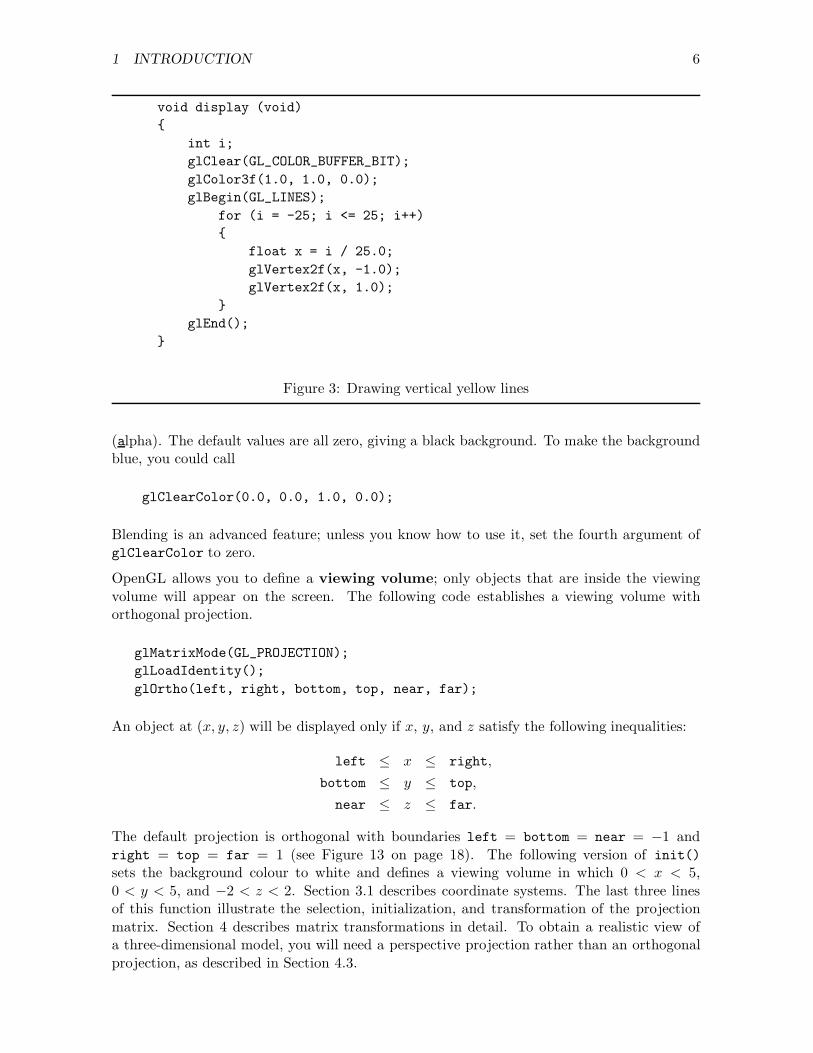
3 Drawing vertical yellow lines . . . . . . . . . . . . . . . . . . . . . . . . . . . . 6
4 Displaying a wire cube . . . . . . . . . . . . . . . . . . . . . . . . . . . . . . . . 9
5 A callback function that rotates the cube . . . . . . . . . . . . . . . . . . . . . 10
6 A keyboard callback function that selects an axis . . . . . . . . . . . . . . . . . 11
7 Quitting with the escape key . . . . . . . . . . . . . . . . . . . . . . . . . . . . 11
8 A callback function that responds to mouse buttons . . . . . . . . . . . . . . . 13
9 A callback function that responds to dragging the mouse . . . . . . . . . . . . . 14
10 A callback function that responds to window reshaping . . . . . . . . . . . . . . 15
11 Maintaining scaling invariants . . . . . . . . . . . . . . . . . . . . . . . . . . . . 16

LIST OF FIGURES iii
12 Drawing primitives . . . . . . . . . . . . . . . . . . . . . . . . . . . . . . . . . . 18
13 Default viewing volume . . . . . . . . . . . . . . . . . . . . . . . . . . . . . . . 18
14 Labelling the corners of a cube . . . . . . . . . . . . . . . . . . . . . . . . . . . 20
15 Drawing a cube . . . . . . . . . . . . . . . . . . . . . . . . . . . . . . . . . . . . 21
16 A balancing act . . . . . . . . . . . . . . . . . . . . . . . . . . . . . . . . . . . . 24
17 Pushing and popping . . . . . . . . . . . . . . . . . . . . . . . . . . . . . . . . . 26
18 Perspective projection with glFrustum() . . . . . . . . . . . . . . . . . . . . . 27
19 Perspective projection using gluPerspective() . . . . . . . . . . . . . . . . . . 28
20 Reshaping with gluPerspective() . . . . . . . . . . . . . . . . . . . . . . . . . 28
21 gluPerspective() with a small value of α . . . . . . . . . . . . . . . . . . . . 29
22 gluPerspective() with a large value of α . . . . . . . . . . . . . . . . . . . . . 29
23 Using gluLookAt() and gluPerspective() . . . . . . . . . . . . . . . . . . . . 31
24 OpenGL Coordinates . . . . . . . . . . . . . . . . . . . . . . . . . . . . . . . . . 32
25 A simple object . . . . . . . . . . . . . . . . . . . . . . . . . . . . . . . . . . . . 34
26 Computing normals . . . . . . . . . . . . . . . . . . . . . . . . . . . . . . . . . 36
27 Computing average normals on a square grid . . . . . . . . . . . . . . . . . . . 37
28 Using glMaterial() . . . . . . . . . . . . . . . . . . . . . . . . . . . . . . . . . 39
29 Illuminating the sun . . . . . . . . . . . . . . . . . . . . . . . . . . . . . . . . . 42
30 Displaying two windows: first part . . . . . . . . . . . . . . . . . . . . . . . . . 43
31 Displaying two windows: second part . . . . . . . . . . . . . . . . . . . . . . . . 44
32 Code for a simple menu . . . . . . . . . . . . . . . . . . . . . . . . . . . . . . . 47
33 Displaying a string of text . . . . . . . . . . . . . . . . . . . . . . . . . . . . . . 48
34 Stroked fonts: first part . . . . . . . . . . . . . . . . . . . . . . . . . . . . . . . 49
35 Stroked fonts: second part . . . . . . . . . . . . . . . . . . . . . . . . . . . . . . 50
36 Obtaining and reporting OpenGL errors . . . . . . . . . . . . . . . . . . . . . . 52
37 Basic transformations . . . . . . . . . . . . . . . . . . . . . . . . . . . . . . . . 57
38 Perspective transformation . . . . . . . . . . . . . . . . . . . . . . . . . . . . . 60
39 Illuminating an object . . . . . . . . . . . . . . . . . . . . . . . . . . . . . . . . 62
40 Default values for lighting . . . . . . . . . . . . . . . . . . . . . . . . . . . . . . 74

LIST OF TABLES iv
List of Tables
1 OpenGL Types . . . . . . . . . . . . . . . . . . . . . . . . . . . . . . . . . . . . 7
2 Constants for special keys . . . . . . . . . . . . . . . . . . . . . . . . . . . . . . 12
3 Primitive Specifiers . . . . . . . . . . . . . . . . . . . . . . . . . . . . . . . . . . 17
4 Options for drawing polygons . . . . . . . . . . . . . . . . . . . . . . . . . . . . 20
5 Common transformations . . . . . . . . . . . . . . . . . . . . . . . . . . . . . . 23
6 Parameters for glMaterialfv() . . . . . . . . . . . . . . . . . . . . . . . . . . 38
7 Parameters for glLightfv() . . . . . . . . . . . . . . . . . . . . . . . . . . . . 40
8 Parameters for glLightModel() . . . . . . . . . . . . . . . . . . . . . . . . . . 41
9 GLUT objects . . . . . . . . . . . . . . . . . . . . . . . . . . . . . . . . . . . . . 50
10 Fonts for glutBitmapCharacter() . . . . . . . . . . . . . . . . . . . . . . . . . 68
11 Mask bits for clearing . . . . . . . . . . . . . . . . . . . . . . . . . . . . . . . . 68
12 Parameter values for glutGet(state) . . . . . . . . . . . . . . . . . . . . . . . 71
13 Display mode bits . . . . . . . . . . . . . . . . . . . . . . . . . . . . . . . . . . 72
14 Cursor codes . . . . . . . . . . . . . . . . . . . . . . . . . . . . . . . . . . . . . 79
Getting Started with OpenGL
Peter Grogono
1 Introduction
OpenGL consists of three libraries: the Graphics Library (GL); the Graphics Library Utilities(GLU); and the Graphics Library Utilities Toolkit (GLUT). Function names begin with gl,glu, or glut, depending on which library they belong to.
These notes assume that you are programming with GLUT. There are two advantages of usingGLUT:
1. Your programs run under different operating systems (including Windows, Unix, Linux,MacOS, etc.) without requiring changes to the source code.
2. You don’t have to learn the details of window management because they are hidden byGLUT.
These notes do not explain how to use OpenGL with the MS Windows API (in other words,how to write Windows programs that use OpenGL but not GLUT). The OpenGL SuperBible(see reference 5 below) is a good source of information on this topic.
Several versions of these libraries have been implemented. The explanations and programsin these notes are based on the Silicon Graphics implementation. Another implementation,called Mesa, has been installed on the “greek” machines. Implementations are also availablefor PCs running linux, or Windows.
The principal sources for these notes are listed below.
1. OpenGL Programming Guide. Mason Woo, Jackie Neider, Tom Davis, and Dave Shreiner.Third Edition, Addison-Wesley, 1999. The “official guide to learning OpenGL”.
2. OpenGL Reference Manual. Third Edition, Addison-Wesley, 2000.
3. The OpenGL Utility Toolkit (GLUT) Programming Interface. Mark J. Kilgard. SiliconGraphics, 1997.http://www.opengl.org/developers/documentation/glut/index.html
4. The OpenGL Graphics System: a Specification. Mark Segal and Kurt Akeley. SiliconGraphics, 1997.http://www.opengl.org/developers/documentation/specs.html.
5. OpenGL SuperBible. Richard S. Wright, Jr. and Michael Sweet. Second Edition, WaiteGroup Press, 2000.
Since people are constantly changing their web pages and links, you may find that the URLsabove do not work. If so, try going to the OpenGl web site (www.opengl.org) and exploring.
Appendix C contains specifications of all of the functions mentioned in these notes, and a fewothers as well. To use OpenGL effectively, however, you must know not only the specifications
1 INTRODUCTION 2
of individual functions but also the way in which these functions work together in programs.Sections 2 through 6 provide examples of ways in which the functions can be used.
I have tried to make this manual as accurate as possible. If you find errors, omissions, ormisprints, please send an e-mail message to me at [email protected].
1.1 Compiling and Executing an OpenGL Program
OpenGL can be used with various programming languages but, in these notes, we assume thatthe language is C or C++. The source code for an OpenGL program should the followingdirectives. If you are not using GLUT:
#include <GL/gl.h>#include <GL/glu.h>
If you are using GLUT:
#include <GL/glut.h>
When you link an OpenGL program, you must include the OpenGL libraries in the fashionappropriate to the platform you are using. The following sections describe how to use OpenGLwith MS Windows and Linux.
Windows. Include these libraries when you link your program: glu32.lib, opengl32.lib,and glut32.lib. To do this with Visual C++:
• Select Project/Settings/Link.
• In the “Object/library modules:” window, add the name of each library. Library namesare separated by a space. The order of libraries doesn’t matter.
Alternatively, if you are using VC++, you can include the following code in your OpenGLprogram:
#pragma comment(lib, "opengl32.lib")#pragma comment(lib, "glu32.lib")#pragma comment(lib, "glut32.lib")
On some DCS Windows PCs, the header files may be in the directory ...\include ratherthan in the subdirectory ...\include\GL. If this is the case, the directives given above causecompiler errors and, to make them work, you should omit “GL/”.
Linux. You can develop OpenGL programs under Linux using your favourite C or C++compiler. The header files are in /usr/include/GL and the libraries are in /usr/lib.
On DCS PCs, OpenGL programs run much more slowly under Linux than under Windows.The speeds can differ by a factor of five or more. This is because most modern graphicscards are capable of using hardware to execute low-level OpenGL functions. However, thehardware will be exploited only if the appropriate drivers are installed. Suitable drivers havebeen installed for Windows but not, in most cases, for Linux.

1 INTRODUCTION 3
1 #include <GL/glut.h>23 void display (void)4 {5 glClear(GL_COLOR_BUFFER_BIT);6 }78 void init (void)9 {
10 }1112 int main (int argc, char *argv[])13 {14 glutInit(&argc, argv);15 glutInitDisplayMode(GLUT_SINGLE | GLUT_RGBA);16 glutInitWindowSize(800, 600);17 glutInitWindowPosition(100, 50);18 glutCreateWindow("My first openGL program");19 init();20 glutDisplayFunc(display);21 glutMainLoop();22 return 0;23 }
Figure 1: The basic OpenGL program
1.2 Additional Resources
The example programs in these notes have two disadvantages: the first one is that you haveto enter them into your computer before you can see how they work, and the second is thatthey are very short. You can avoid both of these disadvantages by downloading, reading, andcompiling the example programs that I have provided at
http://www.cse.concordia.ca/~grogono/Graphics/graphex.html
I have also started the development of a local library that provides useful functions that arenot built in to OpenGL. You can find details at
http://www.cs.concordia.ca/~grogono/CUGL/
1.3 A Simple OpenGL Program
Figure 1 shows a simple OpenGL program. Although this program does nothing useful, itdefines a pattern that is used by most OpenGL programs. The line numbers are not part ofthe program, but are used in the explanation below.

1 INTRODUCTION 4
Line 1. Every OpenGL program should include GL/glut.h. The file glut.h includes glu.h,gl.h and other header files required by GLUT.
Line 3. You must write a function that displays the graphical objects in your model. Thefunction shown here clears the screen but does not display anything. Your program doesnot call this function explicitly, but it will be called at appropriate times by OpenGL.
Line 5. It is usually a good idea to clear various buffers before starting to draw new objects.The colour buffer, cleared by this call, is where the image of your model is actuallystored.
Line 8. It is a good idea to put “standard initialization” (the glut... calls) in the mainprogram and application dependent initialization in a function with a name like init()or myInit(). We follow this convention in these notes becausae it is convenient togive different bodies for init without having to explain where to put the initializatoinstatements. In this program, the function init() is defined in lines 8 through 10, doesnothing, and is invoked at line 19.
Line 14. The function glutInit() initializes the OpenGL library. It is conventional to passthe command line arguments to this function because it may use some of them. Youwill probably not need this feature.
Line 15. The function glutInitDisplayMode() initializes the display. Its argument is a bitstring. Deleting this line would not affect the execution of the program, because thearguments shown are the default values.
Line 16. This call requests a graphics window 800 pixels wide and 600 pixels high. If this linewas omitted, GLUT would use the window manager’s default values for the window’ssize.
Line 17. This call says that the left side of the graphics window should be 100 pixels fromthe left of the screen and the top of the graphics window should be 50 pixels below thetop of the screen. Note that the Y value is measured from the top of the screen. Ifthis line was omitted, GLUT would use the window manager’s default values for thewindow’s position.
Line 18. This call creates the window using the settings given previously. The text in theargument becomes the title of the window. The window does not actually appear onthe screen until glutMainLoop() has been called.
Line 19. This is a good place to perform any additional initialization that is needed (seeabove). Some initialization, such as calls to glEnable(), must come after the call toglutCreateWindow().
Line 20. This call registers the callback function display(). After executing the call,OpenGL knows what function to call to display your model in the window. Section 2describes callback functions.
Line 21. The last statement of an OpenGL program calls glutMainLoop(). This functionprocesses events until the program is terminated. Well-written programs should providethe user with an easy way of stopping the program, for example by selecting Quit froma menu or by pressing the esc key.

1 INTRODUCTION 5
void display (void){
glClear(GL_COLOR_BUFFER_BIT);glColor3f(1.0, 0.0, 0.0);glBegin(GL_LINES);
glVertex2f(-1.0, 0.0);glVertex2f(1.0, 0.0);
glEnd();glFlush();
}
Figure 2: Displaying a bright red line
1.4 Drawing Objects
All that remains is to describe additions to Figure 1. The first one that we will consider isan improved display() function. Figure 2 shows a function that displays a line. The callglColor3f(1.0,0.0,0.0) specifies the colour of the line as “maximum red, no green, and noblue”.
The construction glBegin(mode); ...; glEnd(); is used to display groups of primitiveobjects. The value of mode determines the kind of object: in this case, GL_LINES tells OpenGLto expect one or more lines given as pairs of vertices. Other values of mode and their effectsare given in Section 3.
In this case, the line goes from (−1, 0) to (1, 0), as specified by the two calls to glVertex2f().If we use the default viewing region, as in Figure 1, this line runs horizontally across thecentre of the window.
The call glFlush() forces previously executed OpenGL commands to begin execution. IfOpenGL is running on a workstation that communicates directly with its graphics subsystem,glFlush() will probably have no effect on the behaviour of the program. It is importantto use it if your program is running, or might be run, in a client/server context, however,because otherwise attempts by the system to optimize packet transfers may prevent goodgraphics performance.
The suffix “3f” indicates that glColor3f() requires three arguments of type GLfloat. Sim-ilarly, glVertex2f() requires two arguments of type GLfloat. Appendix C provides moredetails of this notational convention and explains why it is used.
The code between glBegin() and glEnd() is not restricted to gl calls. Figure 3 shows adisplay function that uses a loop to draw 51 vertical yellow (red + green) lines across thewindow. Section 3 describes some of the other primitive objects available in OpenGL.
The call glClear(GL_COLOR_BUFFER_BIT) clears the colour buffer to the background colour.You can set the background colour by executing
glClearColor(r, g, b, a);
with appropriate values of r, g, b, and a during initialization. Each argument is a floating-point number in the range [0, 1] specifying the amount of a colour (red, green, blue) or blending
1 INTRODUCTION 6
void display (void){
int i;glClear(GL_COLOR_BUFFER_BIT);glColor3f(1.0, 1.0, 0.0);glBegin(GL_LINES);
for (i = -25; i <= 25; i++){
float x = i / 25.0;glVertex2f(x, -1.0);glVertex2f(x, 1.0);
}glEnd();
}
Figure 3: Drawing vertical yellow lines
(alpha). The default values are all zero, giving a black background. To make the backgroundblue, you could call
glClearColor(0.0, 0.0, 1.0, 0.0);
Blending is an advanced feature; unless you know how to use it, set the fourth argument ofglClearColor to zero.
OpenGL allows you to define a viewing volume; only objects that are inside the viewingvolume will appear on the screen. The following code establishes a viewing volume withorthogonal projection.
glMatrixMode(GL_PROJECTION);glLoadIdentity();glOrtho(left, right, bottom, top, near, far);
An object at (x, y, z) will be displayed only if x, y, and z satisfy the following inequalities:
left ≤ x ≤ right,
bottom ≤ y ≤ top,
near ≤ z ≤ far.
The default projection is orthogonal with boundaries left = bottom = near = −1 andright = top = far = 1 (see Figure 13 on page 18). The following version of init()sets the background colour to white and defines a viewing volume in which 0 < x < 5,0 < y < 5, and −2 < z < 2. Section 3.1 describes coordinate systems. The last three linesof this function illustrate the selection, initialization, and transformation of the projectionmatrix. Section 4 describes matrix transformations in detail. To obtain a realistic view ofa three-dimensional model, you will need a perspective projection rather than an orthogonalprojection, as described in Section 4.3.

1 INTRODUCTION 7
Suffix Data type C Type OpenGL Type
b 8-bit integer signed char GLbyte
s 16-bit integer short GLshort
i 32-bit integer int or long GLint, GLsizeif 32-bit floating point float GLfloat, GLclampfd 64-bit floating point double GLdouble, GLclampdub 8-bit unsigned integer unsigned char GLubyte, GLbooleanus 16-bit unsigned integer unsigned short GLushort
ui 32-bit unsigned integer unsigned int GLuint, GLenum, GLbitfieldNothing void GLvoid
Table 1: OpenGL Types
void init (void){
glClearColor(1.0, 1.0, 1.0, 0.0);glMatrixMode(GL_PROJECTION);glLoadIdentity();glOrtho(0.0, 5.0, 0.0, 5.0, -2.0, 2.0);
}
1.5 OpenGL Types
OpenGL defines a number of types that are usually equivalent to C types. You can use Ctypes but, if you want to write portable OpenGL programs, it is better to use the OpenGLtypes: see Table 1. The suffix column contains the letter that is used in function names; forexample, the “f” in glVertex3f.

2 CALLBACKS 8
2 Callbacks
GLUT handles events with callback functions. If you want to handle an event, such as akeystroke or mouse movement, you write a function that performs the desired action. Thenyou register your function by passing its name as an argument to a function with a name ofthe form glut...Func(), in which “...” indicates which callback you are registering.
Since OpenGL defines the argument lists of callback functions, you usually cannot pass infor-mation in function arguments. Instead, you have to violate the programming practices youhave been taught and use global variables. (It is possible to eliminate most of the globalvariables by using objedct oriented programming techniques: see my web pages for simpleexamples.) Typical OpenGL programs usually contain the following components:
• declarations of global variables whose values affect the scene;
• a display() function that uses the global variables to draw the scene; and
• one or more callback functions that respond to events by changing the values of theglobal variables.
The program in Figure 4 illustrates these conventions. It displays a wire-frame cube which isrotated about the X , Y , and Z axes by the angles x_angle, y_angle, and z_angle, whichare stored as global variables with initial values zero. We will add callback functions to thisprogram to rotate the cube. The comment “Callback registration here” in the mainprogram shows where the callbacks should be registered.
There is one callback function that must be declared in all OpenGL programs: it is thedisplay callback, and it is registered by calling glutDisplayFunc() with the name of thedisplay function as its argument, as shown in Figure 4.
2.1 The Idle Function
OpenGL calls the idle function when it has nothing else to do. The most common applicationof the idle function is to provide continuous animation. We will use the idle function to makethe cube in Figure 4 rotate. The axis of rotation is determined by the global variable axis,and is the X-axis initially.
1. The main program must register the idle function. The following call registers an idlefunction called spin():
glutIdleFunc(spin);
2. The idle function must be declared. It has no arguments and returns no results. Figure 5shows an idle function that increments one of the angles by 1◦ (one degree) and requeststhat the model be redisplayed. The global variable axis determines which angle isincremented.

2 CALLBACKS 9
#include <GL/glut.h>
#define SIZE 500
float x_angle = 0.0;float y_angle = 0.0;float z_angle = 0.0;enum { X, Y, Z } axis = X;
void display (void){
glClear(GL_COLOR_BUFFER_BIT);glMatrixMode(GL_MODELVIEW);glLoadIdentity();glRotatef(x_angle, 1.0, 0.0, 0.0);glRotatef(y_angle, 0.0, 1.0, 0.0);glRotatef(z_angle, 0.0, 0.0, 1.0);glutWireCube(1.0);glutSwapBuffers();
}
void init (void){
glMatrixMode(GL_PROJECTION);glLoadIdentity();glOrtho(-5.0, 5.0, -5.0, 5.0, -5.0, 5.0);
}
int main (int argc, char *argv[]){
glutInit(&argc, argv);glutInitDisplayMode(GLUT_DOUBLE | GLUT_RGB);glutInitWindowSize(SIZE, SIZE);glutInitWindowPosition(100, 50);glutCreateWindow("Rotating a wire cube");init();/* Callback registration here */glutDisplayFunc(display);glutMainLoop();
}
Figure 4: Displaying a wire cube

2 CALLBACKS 10
void spin (void){
switch (axis){
case X:x_angle += 1.0;break;
case Y:y_angle += 1.0;break;
case Z:z_angle += 1.0;break;
default:break;
}glutPostRedisplay();
}
Figure 5: A callback function that rotates the cube
Notice that, after changing the angle, spin() does not call display() directly. Instead, itcalls glutPostRedisplay(), which informs glutMainLoop() to redisplay the model at thenext convenient opportunity.
You should always use glutPostRedisplay() and you should almost never call the displayfunction directly. OpenGL handles many kinds of events and it may receive several requeststo re-display before it actually gets around to doing so; thus it is more efficient to request are-display rather than to force it.
2.2 Keyboard Callback Functions
If the program has registered a keyboard callback function, the keyboard callback function iscalled whenever the user presses a key. The following steps modify the cube program so thatit responds to the keys ‘x’, ‘y’, and ‘z’ by changing the axis of rotation of the cube.
1. Register a keyboard callback function.
glutKeyboardFunc(keyboard);
2. Figure 6 shows a keyboard callback function. It receives three arguments: the key thatwas pressed, and the current X and Y coordinates of the mouse.
It would be possible to rewrite keyboard() so that it called glutPostRedisplay() once only,after the switch statement. The advantage of the code shown is that the scene is redisplayedonly when one of the keys x, y, or z has been pressed; other keys are ignored.

2 CALLBACKS 11
void keyboard (unsigned char key, int x, int y){
switch (key){
case ’x’:axis = X;glutPostRedisplay();break;
case ’y’:axis = Y;glutPostRedisplay();break;
case ’z’:axis = Z;glutPostRedisplay();break;
default:break;
}}
Figure 6: A keyboard callback function that selects an axis
#define ESCAPE 27
void keyboard (unsigned char key, int x, int y){
if (key == ESCAPE)exit(0);
}
Figure 7: Quitting with the escape key
The callback function registered by glutKeyboardFunc() recognizes only keys correspondingto ASCII graphic characters and esc, backspace, and delete. The keyboard callbackfunction in Figure 7 is a useful default keyboard function: it allows the user to quit theprogram by pressing the escape key.
To make your program respond to other keys, such as the arrow keys and the function (“F”)keys:
1. Register a special key callback function.
glutSpecialFunc(special);
2. Declare the special key function as follows:

2 CALLBACKS 12
GLUT_KEY_F1 GLUT_KEY_F8 GLUT_KEY_UP
GLUT_KEY_F2 GLUT_KEY_F9 GLUT_KEY_DOWN
GLUT_KEY_F3 GLUT_KEY_F10 GLUT_KEY_PAGE_UP
GLUT_KEY_F4 GLUT_KEY_F11 GLUT_KEY_PAGE_DOWN
GLUT_KEY_F5 GLUT_KEY_F12 GLUT_KEY_HOME
GLUT_KEY_F6 GLUT_KEY_LEFT GLUT_KEY_END
GLUT_KEY_F7 GLUT_KEY_RIGHT GLUT_KEY_INSERT
Table 2: Constants for special keys
void special (int key, int x, int y){
switch (key){case GLUT_KEY_F1:
// code to handle F1 keybreak;
....}
}
The arguments that OpenGL passes to special() are: the key code, as defined in Table 2;the X coordinate of the mouse; and the Y coordinate of the mouse.
Within a keyboard or special callback function, you can call glutGetModifiers() (page 71)to find out whether any shift, alt, ctrl are pressed.
2.3 Mouse Event Callback Functions
There are several ways of using the mouse and two ways of responding to mouse activity. Thefirst callback function responds to pressing or releasing one of the mouse buttons.
1. Register a mouse callback function.
glutMouseFunc(mouse_button);
2. The mouse callback function is passed four arguments.
• The first argument specifies the button. Its value is one of GLUT_LEFT_BUTTON,GLUT_MIDDLE_BUTTON, or GLUT_RIGHT_BUTTON.
• The second argument specifies the button state. Its value is one of GLUT_DOWN (thebutton has been pressed) or GLUT_UP (the button has been released).
• The remaining two arguments are the X and Y coordinates of the mouse.

2 CALLBACKS 13
void mouse_button (int button, int state, int x, int y){
double new_angle = x * 360.0 / SIZE;if (button == GLUT_LEFT_BUTTON && state == GLUT_DOWN){
x_angle = new_angle;glutPostRedisplay();
}else if (button == GLUT_MIDDLE_BUTTON && state == GLUT_DOWN){
y_angle = new_angle;glutPostRedisplay();
}else if (button == GLUT_RIGHT_BUTTON && state == GLUT_DOWN){
z_angle = new_angle;glutPostRedisplay();
}}
Figure 8: A callback function that responds to mouse buttons
Figure 8 shows a mouse function that uses the mouse buttons to select the axis of rotationand the X position of the mouse to set the value of the corresponding angle. The value ofnew_angle will be 0 if the mouse cursor is at the left of the OpenGL window and 360 if themouse cursor is at the right of the window. If the user has changed the width of the window,the value of SIZE will be wrong, and the results will be different; Section 2.4 shows how youcan avoid this problem.
An OpenGL program can also respond to “dragging” events in which the user holds a mousebutton down and moves the mouse.
1. Register a callback function for mouse dragging events:
glutMotionFunc(drag);
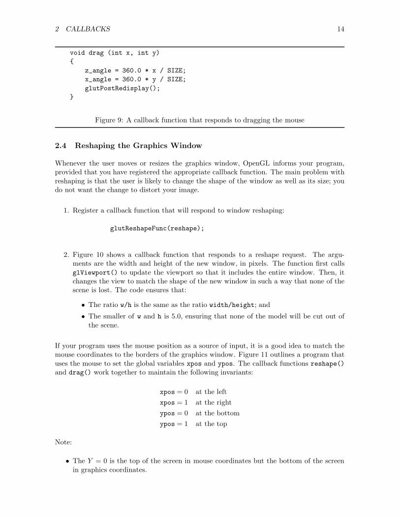
2. The motion function is given the X and Y coordinates of the mouse. Figure 9 shows amotion function that uses the position of the mouse to set z_angle and x_angle.
The function glutPassiveMotionFunc() is similar but registers a callback function thatresponds to mouse movement when no buttons have been pressed.
Within a mouse callback function, you can call glutGetModifiers() to find out whether anyshift, alt, ctrl are pressed.
2 CALLBACKS 14
void drag (int x, int y){
z_angle = 360.0 * x / SIZE;x_angle = 360.0 * y / SIZE;glutPostRedisplay();
}
Figure 9: A callback function that responds to dragging the mouse
2.4 Reshaping the Graphics Window
Whenever the user moves or resizes the graphics window, OpenGL informs your program,provided that you have registered the appropriate callback function. The main problem withreshaping is that the user is likely to change the shape of the window as well as its size; youdo not want the change to distort your image.
1. Register a callback function that will respond to window reshaping:
glutReshapeFunc(reshape);
2. Figure 10 shows a callback function that responds to a reshape request. The argu-ments are the width and height of the new window, in pixels. The function first callsglViewport() to update the viewport so that it includes the entire window. Then, itchanges the view to match the shape of the new window in such a way that none of thescene is lost. The code ensures that:
• The ratio w/h is the same as the ratio width/height; and
• The smaller of w and h is 5.0, ensuring that none of the model will be cut out ofthe scene.
If your program uses the mouse position as a source of input, it is a good idea to match themouse coordinates to the borders of the graphics window. Figure 11 outlines a program thatuses the mouse to set the global variables xpos and ypos. The callback functions reshape()and drag() work together to maintain the following invariants:
xpos = 0 at the leftxpos = 1 at the rightypos = 0 at the bottomypos = 1 at the top
Note:
• The Y = 0 is the top of the screen in mouse coordinates but the bottom of the screenin graphics coordinates.

2 CALLBACKS 15
void reshape (int width, int height){
GLfloat w, h;glViewport(0, 0, width, height);glMatrixMode(GL_PROJECTION);glLoadIdentity();if (width > height){
w = (5.0 * width) / height;h = 5.0;
}else{
w = 5.0;h = (5.0 * height) / width;
}glOrtho(-w, w, -h, h, -5.0, 5.0);glutPostRedisplay();
}
Figure 10: A callback function that responds to window reshaping
• The code does not ensure that 0 ≤ xpos ≤ 1 or 0 ≤ ypos ≤ 1 because some windowsystems allow the user to drag the mouse outside an application’s window without theapplication giving up control.
• The function reshape() computes the aspect ratio of the new window and passes it togluPerspective() to set up a perspective projection.
The reshape callback function responds to a user action that changes the shape of the window.You can also change the shape or position of a window from within your program by callingglutReshapeWindow() or glutPositionWindow().

2 CALLBACKS 16
#include <GL/glut.h>
int screen_width = 600;int screen_height = 400;GLfloat xpos = 0.0;GLfloat ypos = 0.0;
void display (void){
/* display the model using xpos and ypos */}
void drag (int mx, int my){
xpos = (GLfloat) mx / screen_width;ypos = 1.0 - (GLfloat) my / screen_height;glutPostRedisplay();
}
void reshape (int width, int height){
screen_width = width;screen_height = height;glViewport(0, 0, width, height);glMatrixMode(GL_PROJECTION);glLoadIdentity();gluPerspective(30.0, (GLfloat) width / (GLfloat) height, 1.0, 20.0);glutPostRedisplay();
}
int main (int argc, char *argv[]){
glutInit(&argc, argv);glutInitDisplayMode(GLUT_RGB);glutInitWindowSize(screen_width, screen_height);glutCreateWindow("Demonstration of reshaping");glutDisplayFunc(display);glutMotionFunc(drag);glutReshapeFunc(reshape);glutMainLoop();
}
Figure 11: Maintaining scaling invariants

3 PRIMITIVE OBJECTS 17
3 Primitive Objects
The display() callback function usually contains code to render your model into graphicalimages. All models are built from primitive parts. There are a few functions for familiarobjects, such as spheres, cones, cylinders, toruses, and teapots, but you have to build othershapes yourself. OpenGL provides functions for drawing primitive objects, including points,lines, and polygons. There are also various short-cuts for drawing the sets of related polygons(usually triangles) that approximate three-dimensional surfaces.
The code for drawing primitives has the general form
glBegin(mode);.....glEnd();
Table 3 explains what OpenGL expects for each value of the parameter mode. Assume, ineach case, that the code specifies n vertices v0, v1, v2, . . . , vn−1. For some modes, n should bea multiple of something: e.g., for GL_TRIANGLES, n will normally be a multiple of 3. It is notan error to provide extra vertices, but OpenGL will ignore them. The polygon drawn in modeGL_POLYGON must be convex.
Figure 12 shows how the vertices of triangle and quadrilateral collections are labelled. Thelabel numbers are important, to ensure both that the topology of the object is correct andthat the vertices appear in counter-clockwise order (see Section 3.4).
Separate triangles are often easier to code than triangle strips or fans. The trade-off is thatyour program will run slightly more slowly, because you will have multiple calls for each vertex.
Mode Value Effect
GL_POINTS Draw a point at each of the n vertices.GL_LINES Draw the unconnected line segments v0v1, v2v3, . . .vn−2vn−1.
GL_LINE_STRIP Draw the connected line segments v0v1, v1v2, . . . , vn−2vn−1.GL_LINE_LOOP Draw a closed loop of lines v0v1, v1, v2, . . . , vn−2vn−1, vn−1v0.GL_TRIANGLES Draw the triangle v0v1v2, then the triangle v3v4v5, and so on.
GL_TRIANGLE_STRIP Draw the triangle v0v1v2, then use v3 to draw a second triangle,and so on (see Figure 12 (a)).
GL_TRIANGLE_FAN Draw the triangle v0v1v2, then use v3 to draw a second triangle,and so on (see Figure 12 (b)).
GL_QUADS Draw the quadrilateral v0v1v2v3, then the quadrilateral v4v5v6v7,and so on.
GL_QUAD_STRIP Draw the quadrilateral v0v1v3v2, then the quadrilateral v2v3v5v4,and so on (see Figure 12 (c)).
GL_POLYGON Draw a single polygon using v0, v1, . . . , vn−1 as vertices (n ≥ 3).
Table 3: Primitive Specifiers

3 PRIMITIVE OBJECTS 18
rv0
rv1
rv2
rv3
rv4
rv5
����A
AAA
����
�������
����
AAAA
HHHH
�� rv0
rv1 rv2
rv3rv4
��
��
@@
HHHH
��
rv0
rv1
rv2
rv3
rv4
rv5
rv6
rv7
HHHH��
����
�������
HHHH
(a) GL TRIANGLE STRIP (b) GL TRIANGLE FAN (c) GL QUAD STRIP
Figure 12: Drawing primitives
window border
?
��������
��������
��������
��������
−1 x 1−1
y
1
1
z
−1 - X
6Y
�����Z
Figure 13: Default viewing volume
3.1 The Coordinate System
When we draw an object, where will it be? OpenGL objects have four coordinates: x, y, z,and w. The first two, x and y must always be specified. The z coordinate defaults to 0. Thew coordinate defaults to 1. (Appendix A.1 explains the use of w.) Consequently, a call toglVertex() may have 2, 3, or (occasionally) 4 arguments.
Objects are visible only if they are inside the viewing volume. By default, the viewingvolume is the 2 × 2 cube bounded by −1 ≤ x ≤ 1, −1 ≤ y ≤ 1, and −1 ≤ z ≤ 1, with thescreen in the plane z = 0: see Figure 13. The projection is orthographic (no perspective),as if we were viewing the window from infinitely far away.
The following code changes the boundaries of the viewing volume but maintains an ortho-graphic projection:
glMatrixMode(GL_PROJECTION);

3 PRIMITIVE OBJECTS 19
glLoadIdentity();glOrtho(left, right, bottom, top, near, far);
An object at (x, y, z) will be visible if left ≤ x ≤ right, bottom ≤ y ≤ top, and −near ≤z ≤ −far. Note the sign reversal in the Z-axis: this convention ensures that the coordinatesystem is right-handed.
For many purposes, a perspective transformation (see Section 4.3) is better than an ortho-graphic transformation. Section 4.5 provides further details of OpenGL’s coordinate systems.
3.2 Points
The diameter of a point is set by glPointSize(size). The initial value of size is 1.0.
The unit of size is pixels. The details are complicated because the actual size and shapeof a point larger than one pixel in diameter depend on the implementation of OpenGL andwhether or not anti-aliasing is in effect. If you set size > 1, the result may not be preciselywhat you expect.
3.3 Lines
The width of a line is set by glLineWidth(size). The default value of size is 1.0. The unitis pixels: see the note about point size above.
To draw stippled (or dashed) lines, use the following code:
glEnable(GL_LINE_STIPPLE);glLineStipple(factor, pattern);
The pattern is a 16-bit number in which a 0-bit means “don’t draw” and a 1-bit means “dodraw”. The factor indicates how much the pattern should be “stretched”.
Example: After the following code has been executed, lines will be drawn as 10× 10 pixelsquares separated by 10 pixels (note that A16 = 10102).
glEnable(GL_LINE_STIPPLE);glLineWidth(10.0);glLineStipple(10, 0xAAAA);
3.4 Polygons
The modes GL_POINTS, GL_LINES, GL_LINE_STRIP, and GL_LINE_LOOP are straightforward.The other modes all describe polygons of one sort or another.
The way in which polygons are drawn is determined by calling glPolygonMode(face, mode);.Table 4 shows the possible values of face and mode.
How do we decide which is the front of a polygon? The rule that OpenGL uses is: if thevertices appear in a counter-clockwise order in the viewing window, we are looking at thefront of the polygon. If we draw a solid object, such as a cube, the “front” of each face shouldbe the “outside”. The distinction between front and back does not matter in the defaultmode, in which the front and back sides of a polygon are treated in the same way.

3 PRIMITIVE OBJECTS 20
face mode
GL_FRONT_AND_BACK (default) GL_FILL (default)GL_FRONT GL_LINE
GL_BACK GL_POINT
Table 4: Options for drawing polygons
��������
��������
��������
��������
0
1 2
3
4
56
7
Figure 14: Labelling the corners of a cube
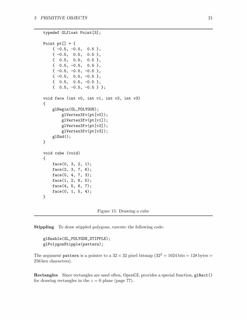
Example: Suppose that we want to draw a unit cube centered at the origin, with verticesnumbered as in Figure 14. Figure 15 shows the code required.
We begin by declaring an array pt giving the coordinates of each vertex. Next, we declare afunction face() that draws one face of the cube. Finally, we declare a function cube() thatdraws six faces, providing the vertices in counter-clockwise order when viewed from outsidethe cube.
Polygons must be convex. The effect of drawing a concave or re-entrant (self-intersecting)polygon is undefined. If necessary, convert a concave polygon to two or more convex polygonsby adding internal edges.
Colouring The function call glShadeModel(mode) determines the colouring of polygons.By default, mode is GL_SMOOTH, which means that OpenGL will use the colours provided ateach vertex and interpolated colours for all other points. For example, if you draw a rectanglewith red corners at the left and blue corners at the right, the left edge will be red, the rightedge will be blue, and the other points will be shades of purple.
If mode is GL_FLAT, the entire polygon has the same colour as its first vertex.
A set of three points defines a plane. If there are more than three points in a set, there maybe no plane that contains them. OpenGL will draw non-planar “polygons”, but lighting andshading effects may be a bit strange.
3 PRIMITIVE OBJECTS 21
typedef GLfloat Point[3];
Point pt[] = {{ -0.5, -0.5, 0.5 },{ -0.5, 0.5, 0.5 },{ 0.5, 0.5, 0.5 },{ 0.5, -0.5, 0.5 },{ -0.5, -0.5, -0.5 },{ -0.5, 0.5, -0.5 },{ 0.5, 0.5, -0.5 },{ 0.5, -0.5, -0.5 } };
void face (int v0, int v1, int v2, int v3){
glBegin(GL_POLYGON);glVertex3fv(pt[v0]);glVertex3fv(pt[v1]);glVertex3fv(pt[v2]);glVertex3fv(pt[v3]);
glEnd();}
void cube (void){
face(0, 3, 2, 1);face(2, 3, 7, 6);face(0, 4, 7, 3);face(1, 2, 6, 5);face(4, 5, 6, 7);face(0, 1, 5, 4);
}
Figure 15: Drawing a cube
Stippling To draw stippled polygons, execute the following code:
glEnable(GL_POLYGON_STIPPLE);glPolygonStipple(pattern);
The argument pattern is a pointer to a 32× 32 pixel bitmap (322 = 1024 bits = 128 bytes =256 hex characters).
Rectangles Since rectangles are used often, OpenGL provides a special function, glRect()for drawing rectangles in the z = 0 plane (page 77).

3 PRIMITIVE OBJECTS 22
3.5 Hidden Surface Elimination
To obtain a realistic view of a collection of primitive objects, the graphics system must displayonly the objects that the viewer can see. Since the components of the model are typicallysurfaces (triangles, polygons, etc.), the step that ensures that invisible surfaces are not ren-dered is called hidden surface elimination. There are various ways of eliminating hiddensurfaces; OpenGL uses a depth buffer.
The depth buffer is a two-dimensional array of numbers; each component of the array corre-sponds to a pixel in the viewing window. In general, several points in the model will map toa single pixel. The depth-buffer is used to ensure that only the point closest to the viewer isactually displayed.
To enable hidden surface elimination, modify your graphics program as follows:
• When you initialize the display mode, include the depth buffer bit:
glutInitDisplayMode(GLUT_RGBA | GLUT_DEPTH);
• During initialization and after creating the graphics window, execute the following state-ment to enable the depth-buffer test:
glEnable(GL_DEPTH_TEST);
• In the display() function, modify the call to glClear() so that it clears the depth-buffer as well as the colour buffer:
glClear(GL_COLOR_BUFFER_BIT | GL_DEPTH_BUFFER_BIT);
3.6 Animation
If your program has an idle callback function that changes the values of some global variables,OpenGL will display your model repeatedly, giving the effect of animation. The display willprobably flicker, however, because images will be alternately drawn and erased. To avoidflicker, modify your program to use double buffering. In this mode, OpenGL renders theimage into one buffer while displaying the contents of the other buffer.
• When you initialize the display mode, include the double buffer bit:
glutInitDisplayMode(GLUT_RGBA | GLUT_DOUBLE);
• At the end of the display() function include the call
glutSwapBuffers();

4 TRANSFORMATIONS 23
4 Transformations
The effect of a transformation is to move an object, or set of objects, with respect to acoordinate system. Table 5 describes some common transformations. The least importanttransformation is shearing; OpenGL does not provide primitive functions for it.
We can apply transformations to: the model; parts of the model; the camera (or eye) position;and the camera “lens”.
In OpenGL, the first three of these are called “model view” transformations and the last iscalled the “projection” transformation. Note that model transformations and camera trans-formations are complementary: for every transformation that changes the model, there is acorresponding inverse transformation that changes the camera and has the same effect on thescreen.
The OpenGL functions that are used to effect transformations include glMatrixMode(),glLoadIdentity(), glTranslatef(), glRotatef(), and glScalef().
4.1 Model View Transformations
A transformation is represented by a matrix. (Appendix A provides an overview of thetheory of representing transformations as matrices.) OpenGL maintains two current matrices:the model view matrix and the projection matrix. glMatrixMode() selects the currentmatrix; glLoadIdentity() initializes it; and the other functions change it. In the examplebelow, the left column shows typical code and the right column shows the effect in pseudocode.M is the current matrix, I is the identity matrix, T is a translation matrix, R is a rotationmatrix, and × denotes matrix multiplication. The final value of M is I × T × R = T × R.
glMatrixMode(GL MODELVIEW);
glLoadIdentity(); M := I
glTranslatef(x,y,z); M := M × T
glRotatef(a,x,y,z); M := M × R
You might think it natural to draw something and then transform it. OpenGL, however, worksthe other way round: you define the transformations first and then you draw the objects. Thisseems backwards, but actually provides greater flexibility in the drawing process, because wecan interleave drawing and transformation operations — it’s also more efficient. Consider thefollowing pseudocode:
Name EffectTranslate Move or slide along a straight lineRotate Rotate, spin, or twist, about an axis through the originScale Make an object larger or smallerShear Turn rectangles into parallelogramsPerspective Give illusion of depth for 3D objects
Table 5: Common transformations

4 TRANSFORMATIONS 24
1 void display (void)2 {3 glClear(GL_COLOR_BUFFER_BIT);4 glMatrixMode(GL_MODELVIEW);5 glLoadIdentity();6 glutWireCube(1.0);7 glTranslatef(0.0, 0.5, 0.0);8 glRotatef(-90.0, 1.0, 0.0, 0.0);9 glutWireCone(0.5, 2.0, 15, 15);
10 glRotatef(90.0, 1.0, 0.0, 0.0);11 glTranslatef(0.0, 2.5, 0.0);12 glutWireSphere(0.5, 15, 15);13 }
Figure 16: A balancing act
initialize model view matrixdraw object P1do transformation T1draw object P2do transformation T2draw object P3.....
The object P1 is drawn without any transformations: it will appear exactly as defined in theoriginal coordinate system. When the object P2 is drawn, transformation T1 is in effect; ifT1 is a translation, for example, P2 will be displaced from the origin. Then P3 is drawn withtransformations T1 and T2 (that is, the transformation T1× T2) in effect.
In practice, we usually define a camera transformation first, before drawing any objects. Thismakes sense, because changing the position of the camera should change the entire scene. Bydefault, the camera is positioned at the origin and is looking in the negative Z direction.
Although we can think of a transformation as moving either the objects or the coordinate sys-tem, it is often simpler to think of the coordinates moving. The following example illustratesthis way of thinking.
The program balance.c draws a sphere on the top of a cone which is standing on a cube.Figure 16 shows the display callback function that constructs this model (the line numbersare not part of the program).
Line 3 clears the buffer, line 4 selects the model view matrix, and line 5 initialize the matrix.The first object drawn is a unit cube (line 6); since no transformations are in effect, the cubeis at the origin. Since the cone must sit on top of the cube, line 7 translates the coordinatesystem up by 0.5 units.
The axis of the cone provided by GLUT is the Z axis, but we need a cone with its axis in theY direction. Consequently, we rotate the coordinate system (line 8), draw the cone (line 9),and rotate the coordinate system back again (line 10). Note that the rotation in line 10:

4 TRANSFORMATIONS 25
1. does not affect the cone, which has already been drawn; and
2. avoids confusion: if it it was not there, we would have a coordinate system with ahorizontal Y axis and a vertical Z axis.
Line 11 moves the origin to the centre of the sphere, which is 2.0+0.5 units (the height of thecone plus the radius of the sphere) above the top face of the cube. Line 12 draws the sphere.
The example demonstrates that we can start at the origin (the “centre” of the model) andmove around drawing parts of the model. Sometimes, however, we have to get back to aprevious coordinate system. Consider drawing a person, for instance: we could draw thebody, move to the left shoulder, draw the upper arm, move to the elbow joint, draw the lowerarm, move to the wrist, and draw the hand. Then what? How do we get back to the body todraw the right arm?
The solution that OpenGL provides for this problem is a matrix stack. There is not just onemodel view matrix, but a stack that can contain 32 model view matrices. (The specification ofthe API requires a stack depth of at least 32 matrices; implementations may provide more.)The function glPushMatrix() pushes the current matrix onto the stack, and the functionglPopMatrix() pops the current matrix off the stack (and loses it). Using these functions,we could rewrite lines 8–10 of the example as:
glPushMatrix();glRotatef(-90.0, 1.0, 0.0, 0.0);glutWireCone(0.5, 2.0, 15, 15);glPopMatrix();
The stack version is more efficient because it is faster to copy a matrix than it is to constructa new matrix and perform a matrix multiplication. It is always better to push and pop thanto apply inverse transformations.
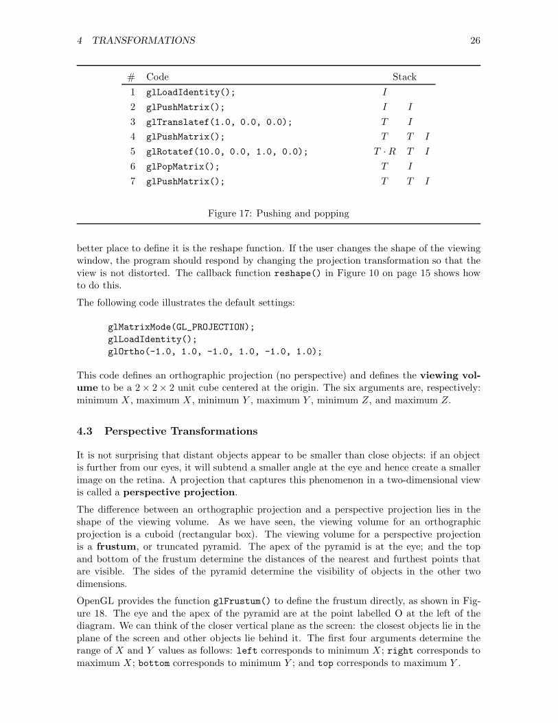
When pushing and popping matrices, it is important to realize that the sequence
glPopMatrix();glPushMatrix();
does have an effect: the two calls do not cancel each other out. To see this, look at Figure 17.The left column contains line numbers for identification, the second column contains code,the third column shows the matrix at the top of the stack after each function has executed,and the other columns show the matrices lower in the stack. The matrices are shown as I(the identity), T (the translation), and R (the rotation). At line 4, there are three matriceson the stack, with T occupying the top two places. Line 5 post-multiplies the top matrix byR. Line 6 pops the product T ·R off the stack, restoring the stack to its value at line 3. Line 7pushes the stack and copies the top matrix. Note the difference between the stack entries atline 5 and line 7.
4.2 Projection Transformations
The usual practice in OpenGL coding is to define a projection matrix once and not to applyany transformations to it. The projection matrix can be defined during initialization, but a
4 TRANSFORMATIONS 26
# Code Stack1 glLoadIdentity(); I
2 glPushMatrix(); I I
3 glTranslatef(1.0, 0.0, 0.0); T I
4 glPushMatrix(); T T I
5 glRotatef(10.0, 0.0, 1.0, 0.0); T · R T I
6 glPopMatrix(); T I
7 glPushMatrix(); T T I
Figure 17: Pushing and popping
better place to define it is the reshape function. If the user changes the shape of the viewingwindow, the program should respond by changing the projection transformation so that theview is not distorted. The callback function reshape() in Figure 10 on page 15 shows howto do this.
The following code illustrates the default settings:
glMatrixMode(GL_PROJECTION);glLoadIdentity();glOrtho(-1.0, 1.0, -1.0, 1.0, -1.0, 1.0);
This code defines an orthographic projection (no perspective) and defines the viewing vol-ume to be a 2× 2× 2 unit cube centered at the origin. The six arguments are, respectively:minimum X , maximum X , minimum Y , maximum Y , minimum Z, and maximum Z.
4.3 Perspective Transformations
It is not surprising that distant objects appear to be smaller than close objects: if an objectis further from our eyes, it will subtend a smaller angle at the eye and hence create a smallerimage on the retina. A projection that captures this phenomenon in a two-dimensional viewis called a perspective projection.
The difference between an orthographic projection and a perspective projection lies in theshape of the viewing volume. As we have seen, the viewing volume for an orthographicprojection is a cuboid (rectangular box). The viewing volume for a perspective projectionis a frustum, or truncated pyramid. The apex of the pyramid is at the eye; and the topand bottom of the frustum determine the distances of the nearest and furthest points thatare visible. The sides of the pyramid determine the visibility of objects in the other twodimensions.
OpenGL provides the function glFrustum() to define the frustum directly, as shown in Fig-ure 18. The eye and the apex of the pyramid are at the point labelled O at the left of thediagram. We can think of the closer vertical plane as the screen: the closest objects lie in theplane of the screen and other objects lie behind it. The first four arguments determine therange of X and Y values as follows: left corresponds to minimum X ; right corresponds tomaximum X ; bottom corresponds to minimum Y ; and top corresponds to maximum Y .

4 TRANSFORMATIONS 27
HHHH
HHHH
O ``````````````````````````````
!!!!!!!!!!!!!!!!!!!!!!!!!!!!!!
��
��
��
��
��
��
��
��
��
HHHHHHHHHHHH
HHHHHHHHHHHH
near� -
far� -
top
right
left
bottom�
��>
Figure 18: Perspective projection with glFrustum()
Note that near and far do not correspond directly to Z values. Both near and far must bepositive, and visible Z values lie in the range −far ≤ Z ≤ −near.
The function gluPerspective() provides another way of defining the frustum that is moreintuitive and often convenient. The first argument defines the vertical angle that the viewportsubtends at the eye in degrees. This angle is called α in Figure 19; its value must satisfy0◦ < α < 180◦. The height of the window is h = 2 ·near · tan(α/2). The second argument, arin Figure 19, is the aspect ratio, which is the width of the viewport divided by its height.Thus w = ar · h = 2 · ar · near · tan(α/2). The last two arguments, near and far, determinethe nearest and furthest points visible.
The presence of the aspect-ratio argument makes it easy to use gluPerspective() in awindow reshaping callback function: Figure 20 shows a typical example.
The model view transformation and the projection transformation must work together in sucha way that at least part of the model lies in the viewing volume. If it doesn’t, we won’t seeanything.
Both projection transformations assume that our camera (or eye) is situated at the originand is looking in the negative Z direction. (Why negative Z, rather than positive Z? Byconvention, the screen coordinates have X pointing right and Y pointing up. If we want aright-handed coordinate system, Z must point towards the viewer.) Consequently, we shouldposition our model somewhere on the negative Z axis.
The value of alpha determines the vertical angle subtended by the viewport at the user’s eye.Figure 21 shows the effect of a small value of alpha. The model is a wire cube whose image

4 TRANSFORMATIONS 28
HHHHHHHH
HHHHHHHH
!!!!!!!!!!!!!!!!!!!!!!!!!!!!!!
O α``````````````````````````````
r r
r
r
r
near� -
far� -
wHHHHY
HHHHj
h
6
?
rHHjX
6Y
�Z
Figure 19: Perspective projection using gluPerspective()
void reshape (int width, int height){
glViewport(0, 0, width, height);glMatrixMode(GL_PROJECTION);glLoadidentity();gluPerspective(30.0, (GLfloat) width / (GLfloat) height, 1, 20);
}
Figure 20: Reshaping with gluPerspective()
occupies half of the viewport. The effect is that of viewing the cube from a large distance:the back of the cube is only slightly smaller than the front.
Figure 22 shows the effect of a large value of alpha. The model is again a wire cube whoseimage occupies half of the viewport. The effect is of viewing the cube from a small distance:the back of the cube is much smaller than the front.
Making alpha smaller without moving the model simulates “zooming in”: the image getslarger in the viewport. Making alpha larger simulates “zooming out”: the image gets smaller.
Although we can use alpha to manipulate the image in any way we please, there is a correctvalue for it. Suppose that the user is sitting at a distance d from a screen of height h: theappropriate value of alpha is given by
α = 2 tan−1(
h
2 d
).
For example, if h = 12 in and d = 24 in, then
α = 2 tan−1
(12
2 × 24
)≈ 28◦.

4 TRANSFORMATIONS 29
view on screen
(((((((((((((((((((((((((((((
hhhhhhhhhhhhhhhhhhhhhhhhhhhhh
α
Figure 21: gluPerspective() with a small value of α
��
@@ ��
@@
view on screen
�������������
αAAAAAAAAAAAAA
Figure 22: gluPerspective() with a large value of α
If you have used a 35 mm camera, you may find the following comparisons helpful. Thevertical height of a 35 mm film frame is h = 24 mm, so h/2 = 12 mm. When the camera isused with a lens with focal length f mm, the vertical angle subtended by the field of view is2 tan−1(12/f). The angle for a 24 mm wide-angle lens is about 53◦; the angle for a regular50 mm lens is about 27◦; and the angle for a 100 mm telephoto lens is about 14◦.
4.4 Combining Viewpoint and Perspective
The function gluLookAt() defines a model-view transformation that simulates viewing (“look-ing at”) the scene from a particular viewpoint. It takes nine arguments of type GLfloat. Thefirst three arguments define the camera (or eye) position with respect to the origin; the nextthree arguments are the coordinates of a point in the model towards which the camera is

4 TRANSFORMATIONS 30
directed; and the last three arguments are the components of a vector pointing upwards. Inthe call
gluLookAt ( 0.0, 0.0, 10.0,0.0, 0.0, 0.0,0.0, 1.0, 0.0 );
the point of interest in the model is at (0, 0, 0), the position of the camera relative to thispoint is (0, 0, 10), and the vector (0, 1, 0) (that is, the Y -axis) is pointing upwards.
Although the idea of gluLookAt() seems simple, the function is tricky to use in practice.Sometimes, introducing a call to gluLookAt() has the undesirable effect of making the imagedisappear altogether! In the following code, the effect of the call to gluLookAt() is to movethe origin to (0, 0,−10); but the near and far planes defined by gluPerspective() are atz = −1 and z = −5, respectively. Consequently, the cube is beyond the far plane and isinvisible.
glMatrixMode(GL_PROJECTION);glLoadIdentity();gluPerspective(30, 1, 1, 5);glMatrixMode(GL_MODELVIEW);glLoadIdentity();gluLookAt ( 0, 0, 10, 0, 0, 0, 0, 1, 0 );glutWireCube(1.0);
Figure 23 demonstrates how to use gluLookAt() and gluPerspective() together. The twoimportant variables are alpha and dist. The idea is that the extension of the object in the Z-direction is less than 2; consequently, it can be enclosed completely by planes at z = dist− 1and z = dist+ 1. To ensure that the object is visible, gluLookAt() sets the camera positionto (0, 0, dist).
Changing the value of alpha in Figure 23 changes the size of the object, as explained above.The height of the viewing window is 2 (dist− 1) tan (alpha/2); increasing alpha makes theviewing window larger and the object smaller.
Changing the value of dist also changes the size of the image in the viewport, but in adifferent way. The perspective changes, giving the effect of approaching (if dist gets smallerand the object gets larger) or going away (if dist gets larger and the object gets smaller).
It is possible to change alpha and dist together in such a way that the size of a key objectin the model stays the same while the perspective changes. (For example, consider a seriesof diagrams that starts with Figure 21 and ends with Figure 22.) This is a rather simpletechnique in OpenGL, but it is an expensive effect in movies or television because the zoomcontrol of the lens must be coupled to the tracking motion of the camera. Hitchcock used thistrick to good effect in his movies Vertigo and Marnie.
4.5 Coordinate Systems
Figure 24 summarizes the different coordinate systems that OpenGL uses and the operationsthat convert one set of coordinates to another.

4 TRANSFORMATIONS 31
#include <GL/glut.h>
const int SIZE = 500;
float alpha = 60.0;float dist = 5.0;
void display (void){
glClear(GL_COLOR_BUFFER_BIT);glMatrixMode(GL_MODELVIEW);glLoadIdentity();gluLookAt ( 0.0, 0.0, dist,
0.0, 0.0, 0.0,0.0, 1.0, 0.0 );
glutWireCube(1.0);}
void init (void){
glMatrixMode(GL_PROJECTION);glLoadIdentity();gluPerspective(alpha, 1.0, dist - 1.0, dist + 1.0);
}
int main (int argc, char *argv[]){
glutInit(&argc, argv);glutInitWindowSize(SIZE, SIZE);glutInitWindowPosition(100, 50);glutCreateWindow("A Perspective View");init();glutDisplayFunc(display);glutMainLoop();
}
Figure 23: Using gluLookAt() and gluPerspective()
• You design your scene in model coordinates.
• The model view matrix transforms your model coordinates to eye coordinates. Forexample, you will probably put the centre of your model at the origin (0, 0, 0). Usingthe simplest model view matrix, a translation t in the negative Z direction, will put thecentre of your model at (0, 0,−t) in eye coordinates.
• The projection matrix transforms eye coordinates into clip coordinates. Any vertexwhose coordinates do not satisfy |x/w| ≤ 1, |y/w| ≤ 1, and |z/w| ≤ 1 removed at thisstage.

4 TRANSFORMATIONS 32
Modelcoordinates
?Apply model view matrix
Eyecoordinates
?Apply projection matrix
Clipcoordinates
?Perform perspective division
Normalized devicecoordinates
?Apply viewport transformation
Windowcoordinates
Figure 24: OpenGL Coordinates
• The (x, y, z, w) coordinates are now replaced by (x/w, y/w/z/w). This is called perspec-tive division and the result is normalized device coordinates.
• Finally, the viewport transformation produces window coordinates.

5 LIGHTING 33
5 Lighting
We talk about “three dimensional” graphics but, with current technology, the best we can dois to create the illusion of three-dimensional objects on a two-dimensional screen. Perspectiveis one kind of illusion, but it is not enough. A perspective projection of a uniformly-colouredcube, for example, looks like an irregular hexagon. We can paint the faces of the cube indifferent colours, but this does not help us to display a realistic image of a cube of one colour.
We can improve the illusion of depth by simulating the lighting of a scene. If a cube isilluminated by a single light source, its faces have different brightnesses, and this strengthensthe illusion that it is three dimensional. Appendix B outlines the theory of illumination; thissection describes some of the features that OpenGL provides for lighting a scene.
To light a model, we must provide OpenGL with information about the objects in the sceneand the lights that illuminate them. To obtain realistic lighting effects, we must define:
1. normal vectors for each vertex of each object;
2. material properties for each object;
3. the positions and other properties of the light sources; and
4. a lighting model.
Since OpenGL provides reasonable defaults for many properties, we have to add only a fewfunction calls to a program to obtain simple lighting effects. For full realism, however, thereis quite a lot of work to do.
5.1 A Simple Example
Suppose that we have a program that displays a sphere. We must eliminate hidden surfacesby passing GLUT_DEPTH to glutInitDisplayMode() and by clearing GL_DEPTH_BUFFER_BITin the display function. The following steps would be necessary to illuminate a sphere.
1. Define normal vectors. If we use the GLUT function glutSolidSphere(), this step isunnecessary, because normals are already defined for the sphere and other GLUT solidobjects.
2. Define material properties. We can use the default properties.
3. Define light sources. The following code should be executed during initialization:
glEnable(GL_LIGHTING);glEnable(GL_LIGHT0);
4. Define a lighting model. We can use the default model.
This is the simplest case, in which we add just two lines of code. The following sectionsdescribe more of the details.

5 LIGHTING 34
��
��
PPPPPP
BBBBBBB
PPPPPP
��
��
0
1
2
3
Figure 25: A simple object
5.2 Normal Vectors
For any plane surface, there is a normal vector at right angles to it. A pencil standingvertically on a horizontal desktop provides an appropriate mental image.
OpenGL associates normals with vertices rather than surfaces. This seems surprising at first,but it has an important advantage. Often, we are using flat polygons as approximations tocurved surfaces. For example, a sphere is constructed of many small rectangles whose edgesare lines of latitude and longitude. If we provide a single normal for each rectangle, OpenGLwill illuminate each rectangle as a flat surface. If, instead, we provide a normal at each vertex,OpenGL will illuminate the rectangles as if they were curved surfaces, and provide a betterillusion of a sphere.
Consequently, there are two ways of specifying normals. Consider the very simple objectshown in Figure 25 consisting of two triangles. We could provide a single normal for eachtriangle using the following code:
glBegin(GL_TRIANGLES);glNormal3f(u0,v0,w0); /* Normal for triangle 012.*/glVertex3f(x0,y0,z0);glVertex3f(x1,y1,z1);glVertex3f(x2,y2,z2);glNormal3f(u1,v1,w1); /* Normal for triangle 132. */glVertex3f(x1,y1,z1);glVertex3f(x3,y3,z3);glVertex3f(x2,y2,z2);
glEnd();
The function glNormal() defines a normal vector for any vertex definitions that follow it.Note that it is possible for two normals to be associated with the same vertex: in the codeabove, vertices 1 and 2 each have two normals. As far as OpenGL is concerned, the codedefines six vertices, each with its own normal.
The other way of describing this object requires a normal for each vertex. The normals atvertices 0 and 3 are perpendicular to the corresponding triangles. The normals at vertices 1and 2 are computed by averaging the normals for the triangles. In the following code, eachvertex definition is preceded by the definition of the corresponding normal.

5 LIGHTING 35
glBegin(GL_TRIANGLES);glNormal3f(u0,v0,w0); /* Normal to triangle 012 */glVertex3f(x0,y0,z0);glNormal3f(ua,va,wa); /* Average */glVertex3f(x1,y1,z1);glNormal3f(ua,va,wa); /* Average */glVertex3f(x2,y2,z2);
glNormal3f(ua,va,wa); /* Average */glVertex3f(x1,y1,z1);glNormal3f(u3,v3,w3); /* Normal to triangle 132 */glVertex3f(x3,y3,z3);glNormal3f(ua,va,wa); /* Average */glVertex3f(x2,y2,z2);
glEnd();
We do not usually see code like this in OpenGL programs, because it is usually more convenientto store the data in arrays. The following example is more typical; each component of thearrays norm and vert is an array of three floats.
glBegin{GL_TRIANGLES}for (i = 0; i < MAX; i++){glNormal3fv(norm[i]);glVertex3fv(vert[i]);
}glEnd();
Each normal vector should be normalized (!) in the sense that its length should be 1. Nor-malizing the vector (x, y, z) gives the vector (x/s, y/s, z/s), where s =
√x2 + y2 + z2.
If you include the statement glEnable(GL_NORMALIZE) in your initialization code, OpenGLwill normalize vectors for you. However, it is usually more efficient to normalize vectorsyourself.
Computing Normal Vectors The vector normal to a triangle with vertices (x1, y1, z1),(x2, y2, z2), and (x3, y3, z3) is (a, b, c), where
a = +
∣∣∣∣∣y2 − y1 z2 − z1
y3 − y1 z3 − z1
∣∣∣∣∣
b = −∣∣∣∣∣
x2 − x1 z2 − z1
x3 − x1 z3 − z1
∣∣∣∣∣
c = +
∣∣∣∣∣x2 − x1 y2 − y1
x3 − x1 y3 − y1
∣∣∣∣∣
To compute the average of n vectors, simply add them up and divide by n. In practice, thedivision by n is not usually necessary, because we can simply add the normal vectors at avertex and then normalize the resulting vector.

5 LIGHTING 36
enum { X, Y, Z };typedef float Point[3];typedef float Vector[3];
Point points[MAX_POINTS];
void find_normal (int p, int q, int r, Vector v) {float x1 = points[p][X];float y1 = points[p][Y];float z1 = points[p][Z];float x2 = points[q][X];float y2 = points[q][Y];float z2 = points[q][Z];float x3 = points[r][X];float y3 = points[r][Y];float z3 = points[r][Z];v[X] = + (y2-y1)*(z3-z1) - (z2-z1)*(y3-y1);v[Y] = - (x2-x1)*(z3-z1) + (z2-z1)*(x3-x1);v[Z] = + (x2-x1)*(y3-y1) - (y2-y1)*(x3-x1);}
Figure 26: Computing normals
Formally, the normalized average vector of a set of vectors { (xi, yi, zi) | i = 1, 2, . . . , n } is(
X
S,Y
S,Z
S
), where X =
i=n∑
i=1
xi, Y =i=n∑
i=1
yi, Z =i=n∑
i=1
zi, and S =√
X2 + Y 2 + Z2.
Figure 26 shows a simple function that computes vector normal for a plane defined by threepoints p, q, and r, chosen from an array of points.
There is a simple algorithm, invented by Martin Newell, for finding the normal to a polygonwith N vertexes. For good results, the vertexes should lie approximately in a plane, butthe algorithm does not depend on this. If the vertexes have coordinates (xi, yi, zi) for i =0, 1, 2, ..., N − 1, the normal n = (nx, ny, nz) is computed as
nx =∑
0≤i<N
(yi − yi+1)(zi + zi+1)
nx =∑
0≤i<N
(zi − zi+1)(xi + xi+1)
nx =∑
0≤i<N
(xi − xi+1)(yi + yi+1).
The subscript i + 1 is computed “mod N”: if i = N − 1, then i + 1 = 0. The result n mustbe divided by ‖n‖ =
√n2
x + n2y + n2
z to obtain a unit vector.
A general purpose formula can often be simplified for special cases. Suppose that we areconstructing a terrain using squares and that the X and Y coordinates are integer multipliesof the grid spacing, d. The height of the terrain at x = i and y = j is is zi,j . Figure 27shows 9 points of the terrain, centered at zi,j . The X coordinates in this view are i− 1, i, and

5 LIGHTING 37
j − 1
j
j + 1
i − 1 i i + 1
ttt
ttt
ttt� d - � d -
?
d6
?
d6
A B
CD
Figure 27: Computing average normals on a square grid
i + 1, and the Y coordinates are j − 1, j, and j + 1. The appropriate normal for the point(xi, yi) is the average of the normals to the quadrilaterals A, B, C, and D. Using Newell’sformula to compute these four normals and adding the resulting vectors gives a vector n withcomponents:
nx = d(zi−1,j+1 − zi+1,j+1 + 2zi−1,j − 2zi+1,j + zi−1,j−1 − zi+1,j−1)ny = d(−zi−1,j+1 − 2zi,j+1 − zi+1,j+1 + zi−1,j−1 + 2zi,j−1 + zi+1,j−1)nz = 8 d2
Note that we do not need to include the factor d in the calculation of n since a scalar multipledoes not affect the direction of a vector. The correct normal vector is then obtained bynormalizing n.
5.3 Defining Material Properties
When lighting is enabled, OpenGL ignores glColor() calls. Instead, it computes the colourof each point using information about the lights, the objects, and their relative positions. Thefunction that defines the effect of lighting an object is glMaterialfv() and it requires threearguments.
1. The first argument determines which face we are defining. The possible values areGL_FRONT, GL_BACK, or GL_FRONT_AND_BACK.
It is usually best to use GL_FRONT because, in most situations, only front faces should bevisible. (Recall that a face is at the “front” if its vertices are given in counterclockwiseorder as seen by the viewer.) You can specify different properties for front and backfaces by calling glMaterialfv() twice, once with GL_FRONT and again with GL_BACK.
2. The second argument is a parameter name. Table 6 shows its possible values.
3. The third argument provides the value of the corresponding parameter: it is a pointerto an array.

5 LIGHTING 38
Parameter Meaning DefaultGL_DIFFUSE diffuse colour of material (0.8, 0.8, 0.8, 1.0)GL_AMBIENT ambient colour of material (0.2, 0.2, 0.2, 1.0)GL_AMBIENT_AND_DIFFUSE ambient and diffuseGL_SPECULAR specular colour of material (0.0, 0.0, 0.0, 1.0)GL_SHININESS specular exponent 0.0GL_EMISSION emissive colour of material (0.0.0, 0.0, 1.0)
Table 6: Parameters for glMaterialfv()
The first column of Table 6 shows the parameter names accepted by glMaterialfv(); thesecond column describes the meaning of the parameter; and the third column shows the valuethat will be provided if you do not call glMaterialfv().
The diffuse colour of an object is its colour when it is directly illuminated; it is what wenormally mean when we say, for example, “the book is blue”. The ambient colour of anobject is its colour when it is illuminated by the ambient (or “background”) light in the scene.
For most objects, the diffuse and ambient colours are almost the same. For this reason,OpenGL provides the parameter name GL_AMBIENT_AND_DIFFUSEwhich sets the ambient anddiffuse colours to the same value.
The specular colour of an object produces highlights when the object is directly illuminated.Smooth, polished surfaces give specular reflections but dull, matte objects do not. Specularhighlights usually have the colour of the light source, rather than the object; consequently, ifa specular colour is defined, it is usually white.
The specular exponent determines the smoothness of a specular surface. Its value must bebetween 0.0 and 128.0. A low value gives a large, dull highlight, and a high value gives asmall, bright highlight.
Define an emissive colour for an object if it is emitting light. For example, a light bulb in yourmodel would have an emissive colour of white or almost white. Defining an emissive colourdoes not make the object a source of light: you must put a light source at the same positionin the scene to provide the light.
Figure 28 shows some examples of the use of glMaterialfv(). Properties do not automati-cally revert to their defaults: if you want to restore a default value, you must do so explicitly.For example, the shininess of the dark blue sphere must be turned off before drawing the dullred cube.
5.4 Defining the Lights
To use lighting, you must first enable it by calling glEnable(GL_LIGHTING). You must alsoenable each light that you want to use. OpenGL provides eight lights, named GL_LIGHT0through GL_LIGHT7. To enable light n, call glEnable(GL_LIGHTn).
The function glLightfv() specifies the properties of a light and is used in the same wayas glMaterialfv(). There are three arguments: the first specifies a light, the second is a
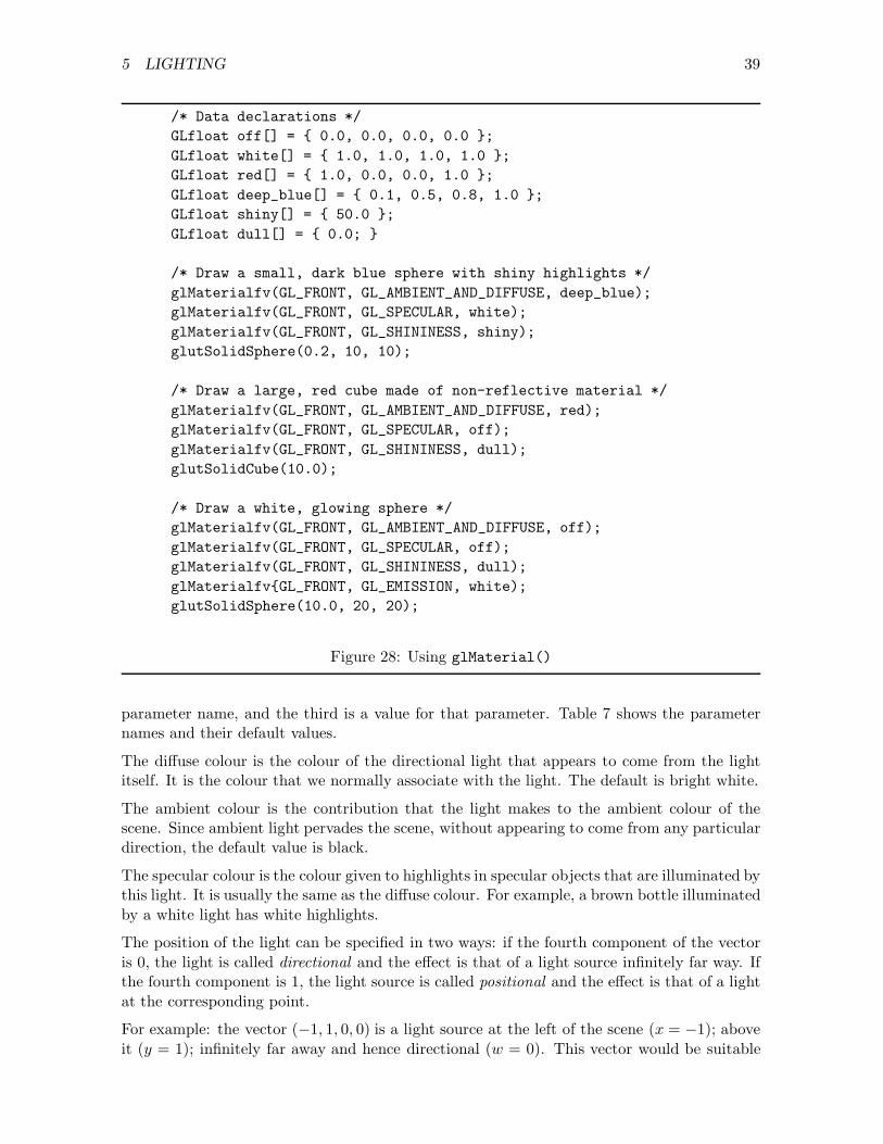
5 LIGHTING 39
/* Data declarations */GLfloat off[] = { 0.0, 0.0, 0.0, 0.0 };GLfloat white[] = { 1.0, 1.0, 1.0, 1.0 };GLfloat red[] = { 1.0, 0.0, 0.0, 1.0 };GLfloat deep_blue[] = { 0.1, 0.5, 0.8, 1.0 };GLfloat shiny[] = { 50.0 };GLfloat dull[] = { 0.0; }
/* Draw a small, dark blue sphere with shiny highlights */glMaterialfv(GL_FRONT, GL_AMBIENT_AND_DIFFUSE, deep_blue);glMaterialfv(GL_FRONT, GL_SPECULAR, white);glMaterialfv(GL_FRONT, GL_SHININESS, shiny);glutSolidSphere(0.2, 10, 10);
/* Draw a large, red cube made of non-reflective material */glMaterialfv(GL_FRONT, GL_AMBIENT_AND_DIFFUSE, red);glMaterialfv(GL_FRONT, GL_SPECULAR, off);glMaterialfv(GL_FRONT, GL_SHININESS, dull);glutSolidCube(10.0);
/* Draw a white, glowing sphere */glMaterialfv(GL_FRONT, GL_AMBIENT_AND_DIFFUSE, off);glMaterialfv(GL_FRONT, GL_SPECULAR, off);glMaterialfv(GL_FRONT, GL_SHININESS, dull);glMaterialfv{GL_FRONT, GL_EMISSION, white);glutSolidSphere(10.0, 20, 20);
Figure 28: Using glMaterial()
parameter name, and the third is a value for that parameter. Table 7 shows the parameternames and their default values.
The diffuse colour is the colour of the directional light that appears to come from the lightitself. It is the colour that we normally associate with the light. The default is bright white.
The ambient colour is the contribution that the light makes to the ambient colour of thescene. Since ambient light pervades the scene, without appearing to come from any particulardirection, the default value is black.
The specular colour is the colour given to highlights in specular objects that are illuminated bythis light. It is usually the same as the diffuse colour. For example, a brown bottle illuminatedby a white light has white highlights.
The position of the light can be specified in two ways: if the fourth component of the vectoris 0, the light is called directional and the effect is that of a light source infinitely far way. Ifthe fourth component is 1, the light source is called positional and the effect is that of a lightat the corresponding point.
For example: the vector (−1, 1, 0, 0) is a light source at the left of the scene (x = −1); aboveit (y = 1); infinitely far away and hence directional (w = 0). This vector would be suitable

5 LIGHTING 40
Parameter Meaning DefaultGL_DIFFUSE diffuse colour (1.0, 1.0, 1.0, 1.0)GL_AMBIENT ambient colour (0.0, 0.0, 0.0, 1.0)GL_SPECULAR specular colour (1.0, 1.0, 1.0, 1.0)GL_POSITION position (0.0, 0.0, 1.0, 0.0)GL_CONSTANT ATTENUATION constant attenuation 1.0GL_LINEAR_ATTENUATION linear attenuation 0.0GL_QUADRATIC_ATTENUATION quadratic attenuation 0.0GL_SPOT_DIRECTION direction of spotlight (0.0, 0.0,−1.0)GL_SPOT_CUTOFF cutoff angle of spotlight 180.0GL_SPOT_EXPONENT exponent of spotlight 0.0
Table 7: Parameters for glLightfv()
for sunlight.
The vector (0, 1,−5, 1) is a light source at the top centre (x = 0, y = 1) of the scene; behindit (z = −5); and at a finite distance (w = 1). This vector would be suitable for an overheadlight in a room.
Directional lighting requires less computation than positional lighting because there are fewerangles to calculate.
In the real world, the intensity of a light decreases with distance. OpenGL calls this decrease“attenuation”. There is no attenuation for a directional light because it is infinitely far away.OpenGL attenuates a positional light source by multiplying the intensity of the light by
1C + L d + Q d2
where C is the constant attenuation factor, L is the linear attenuation factor, Q is thequadratic attenuation factor, and d is the distance between the light and the object. Thedefault values are C = 1 and L = Q = 0. Including linear and/or quadratic attenuationfactors increases the realism of the scene at the expense of extra computation.
By default, a light radiates in all directions. A spotlight radiates a cone of light in a particulardirection. Obviously, a directional light cannot be a spotlight. To turn a positional light intoa spotlight, provide the following values:
• GL_SPOT_DIRECTION determines the direction in which the spotlight is pointing.
• GL_SPOT_CUTOFF determines the “spread” of the light. It is the angle between the axisof the cone and the edge of the light beam. The default value, 180◦, corresponds toan omni-directional light (i.e. not a spotlight). If the angle is not 180◦, it must bebetween 0◦ and 90◦. The angle 5◦ gives a highly-focused searchlight effect; the angle90◦ illuminates anything in front of the light but nothing behind it.
• GL_SPOT_EXPONENT determines how the light varies from the axis to the edges of thecone. The default value, 0.0, gives uniform light across the cone; a higher value focusesthe light towards the centre of the cone.
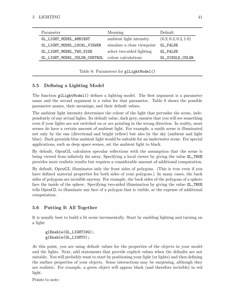
5 LIGHTING 41
Parameter Meaning DefaultGL_LIGHT_MODEL_AMBIENT ambient light intensity (0.2, 0.2, 0.2, 1.0)GL_LIGHT_MODEL_LOCAL_VIEWER simulate a close viewpoint GL_FALSE
GL_LIGHT_MODEL_TWO_SIDE select two-sided lighting GL_FALSE
GL_LIGHT_MODEL_COLOR_CONTROL colour calculations GL_SINGLE_COLOR
Table 8: Parameters for glLightModel()
5.5 Defining a Lighting Model
The function glLightModel() defines a lighting model. The first argument is a parametername and the second argument is a value for that parameter. Table 8 shows the possibleparameter names, their meanings, and their default values.
The ambient light intensity determines the colour of the light that pervades the scene, inde-pendently of any actual lights. Its default value, dark grey, ensures that you will see somethingeven if your lights are not switched on or are pointing in the wrong direction. In reality, mostscenes do have a certain amount of ambient light. For example, a sunlit scene is illuminatednot only by the sun (directional and bright yellow) but also by the sky (ambient and lightblue). Dark greenish-blue ambient light would be suitable for an underwater scene. For specialapplications, such as deep space scenes, set the ambient light to black.
By default, OpenGL calculates specular reflections with the assumption that the scene isbeing viewed from infinitely far away. Specifying a local viewer by giving the value GL_TRUEprovides more realistic results but requires a considerable amount of additional computation.
By default, OpenGL illuminates only the front sides of polygons. (This is true even if youhave defined material properties for both sides of your polygons.) In many cases, the backsides of polygons are invisible anyway. For example, the back sides of the polygons of a sphereface the inside of the sphere. Specifying two-sided illumination by giving the value GL_TRUEtells OpenGL to illuminate any face of a polygon that is visible, at the expense of additionalcomputation.
5.6 Putting It All Together
It is usually best to build a lit scene incrementally. Start by enabling lighting and turning ona light:
glEnable(GL_LIGHTING);glEnable(GL_LIGHT0);
At this point, you are using default values for the properties of the objects in your modeland the lights. Next, add statements that provide explicit values when the defaults are notsuitable. You will probably want to start by positioning your light (or lights) and then definingthe surface properties of your objects. Some interactions may be surprising, although theyare realistic. For example, a green object will appear black (and therefore invisible) in redlight.
Points to note:
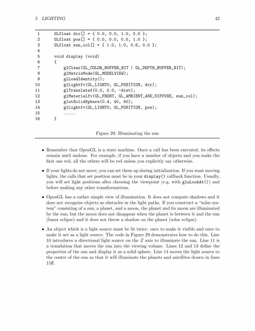
5 LIGHTING 42
1 GLfloat dir[] = { 0.0, 0.0, 1.0, 0.0 };2 GLfloat pos[] = { 0.0, 0.0, 0.0, 1.0 };3 GLfloat sun_col[] = { 1.0, 1.0, 0.6, 0.0 };45 void display (void)6 {7 glClear(GL_COLOR_BUFFER_BIT | GL_DEPTH_BUFFER_BIT);8 glMatrixMode(GL_MODELVIEW);9 glLoadIdentity();
10 glLightfv(GL_LIGHT0, GL_POSITION, dir);11 glTranslatef(0.0, 0.0, -dist);12 glMaterialfv(GL_FRONT, GL_AMBIENT_AND_DIFFUSE, sun_col);13 glutSolidSphere(0.4, 40, 40);14 glLightfv(GL_LIGHT0, GL_POSITION, pos);15 .....16 }
Figure 29: Illuminating the sun
• Remember that OpenGL is a state machine. Once a call has been executed, its effectsremain until undone. For example, if you have a number of objects and you make thefirst one red, all the others will be red unless you explicitly say otherwise.
• If your lights do not move, you can set them up during initialization. If you want movinglights, the calls that set position must be in your display() callback function. Usually,you will set light positions after choosing the viewpoint (e.g. with gluLookAt()) andbefore making any other transformations.
• OpenGL has a rather simple view of illumination. It does not compute shadows and itdoes not recognize objects as obstacles in the light paths. If you construct a “solar sys-tem” consisting of a sun, a planet, and a moon, the planet and its moon are illuminatedby the sun, but the moon does not disappear when the planet is between it and the sun(lunar eclipse) and it does not throw a shadow on the planet (solar eclipse).
• An object which is a light source must be lit twice: once to make it visible and once tomake it act as a light source. The code in Figure 29 demonstrates how to do this. Line10 introduces a directional light source on the Z axis to illuminate the sun. Line 11 isa translation that moves the sun into the viewing volume. Lines 12 and 13 define theproperties of the sun and display it as a solid sphere. Line 14 moves the light source tothe centre of the sun so that it will illuminate the planets and satellites drawn in lines15ff.

6 ODDS AND ENDS 43
6 Odds and Ends
6.1 Multiple Windows
While simple OpenGL programs need only one graphic window, it is sometimes useful to havemore than one window. The windows can be used to present different views of the same sceneor completely different scenes. GLUT makes it very easy to work with multiple windows:
• glutCreateWindow() returns an integer that identifies the window created.
• glutSetWindow(i) makes window i the active window.
• glutGetWindow() returns the number of the active window.
Figures 30 and 31 show a program that illustrates the use of these functions. The mainfunction creates two windows; the keyboard callback function uses the keys 1 and 2 to selectthe current window; and the idle callback function updates two angles at different rates. Whenthis program runs, it displays two windows, each containing a wire cube. The cube in theselected window rotates and the cube in the other window remains stationary.
#include <GL/glut.h>
int firstWindow, secondWindow;float xRotation = 0.0;float yRotation = 0.0;
void displayFirstWindow(){
glClear(GL_COLOR_BUFFER_BIT);glMatrixMode(GL_MODELVIEW);glLoadIdentity();glRotatef(xRotation, 0.0, 0.5, -1.0);glutWireCube(1.0);glutSwapBuffers();
}
void displaySecondWindow(){
glClear(GL_COLOR_BUFFER_BIT);glMatrixMode(GL_MODELVIEW);glLoadIdentity();glRotatef(yRotation, 0.0, 0.5, 1.0);glutWireCube(1.0);glutSwapBuffers();
}
Figure 30: Displaying two windows: first part

6 ODDS AND ENDS 44
void keyboard(unsigned char key, int x, int y){
switch (key){case ’1’:
glutSetWindow(firstWindow);break;
case ’2’:glutSetWindow(secondWindow);break;
case 27:exit(0);
}}
void spin(){
xRotation += 1.0;yRotation += 2.0;glutPostRedisplay();
}
int main(int argc, char *argv[]){
glutInit(&argc, argv);glutInitDisplayMode(GLUT_DOUBLE | GLUT_RGB);
glutInitWindowSize(300, 300);glutInitWindowPosition(100, 100);firstWindow = glutCreateWindow("Window 1");glutDisplayFunc(displayFirstWindow);glutKeyboardFunc(keyboard);
glutInitWindowSize(200, 200);glutInitWindowPosition(100, 500);secondWindow = glutCreateWindow("Window 2");glutDisplayFunc(displaySecondWindow);glutKeyboardFunc(keyboard);
glutIdleFunc(spin);glutMainLoop();return 0;
}
Figure 31: Displaying two windows: second part

6 ODDS AND ENDS 45
Notes:
• The window which is selected is not necessarily the same as the window which is active.A window is selected by clicking when the mouse cursor is inside the window. (InMS Windows, the top bar of the window is blue when the window is selected and greyotherwise. Other window managers use similar conventions.) A window i is active whenglutSetWindow(i) has been called.
When you run the program above, you can select either window with the mouse, butyou can only activate the window (i.e., make the cube in it rotate) by pressing the 1 keyor 2 key.
• glutKeyboardFunc(keyboard) is called twice, once for each window. If it was calledonly once, keystrokes would be recognized only when the corresponding window is se-lected by the mouse.
• The program above has a display callback function for each window. An alternativeapproach is to have just one display callback function that uses glutGetWindow() todetermine which window it is displaying. This is suitable, for example, when the windowsare used to display different views of the same scene. The code would look somethinglike this:
void display(){
glClear(GL_COLOR_BUFFER_BIT);glMatrixMode(GL_MODELVIEW);glLoadIdentity();switch(glutGetWindow()){case Window1:
// Viewing transformations for first window....break;
case Window2:// Viewing transformations for second window....break;
}// Display scene....glutSwapBuffers();
}
• Similar reasoning applies to the other callback functions: depending on the application,you can use a single callback function for all windows, or give each window its owncallback functions, or any combination.
6.2 Menus
GLUT provides menus. The format of menus is restricted but the functions are easy to use.Follow the steps below to define a menu without submenus.

6 ODDS AND ENDS 46
1. Call glutCreateMenu(func) to create the menu. func is the name of a function thatwill handle menu-selection events (see item 4 below).
2. Call glutAddMenuEntry(string,num) for each menu item. string is the string thatwill be displayed in the menu. num is a constant that will be sent to the callback functionwhen the user selects this item. You must ensure that all selections have different values.
3. Call glutAttachMenu(button) to “attach” the menu to a mouse button. button shouldbe one of GLUT_LEFT_BUTTON, GLUT_MIDDLE_BUTTON, or GLUT_RIGHT_BUTTON. (MS Win-dows may not be able to recognize the middle mouse button.)
4. Write the callback function for the menu. This function has one integer argument andreturns nothing. The value passed to it will be one of the constants that you chose instep 2.
Figure 32 shows an example of the code required for a simple menu. The initialization func-tion initialize menu() must be called explicitly by the application program. The callbackfunction choose colour() is not called by the program but will be called by GLUT when theuser has invoked the menu by pressing the right mouse button and has made a selection fromthe menu.
Follow the steps below to obtain menus with submenus.
1. To create a submenu, call glutCreateMenu() as before. This time, however, you shouldkeep a copy of the integer that it returns. Suppose, for example, that you write
int sub1 = glutCreateMenu(get_key);
2. Complete the submenu with calls to glutAddMenuEntry(), but do not attach it to abutton.
3. Write code for the main menu after the submenus. (That is, build the menu “tree”bottom-up.) To add a submenu to the main menu, call glutAddSubMenu(string,num).string is the text that appears in the main menu to identify the submenu and num isthe value returned by glutCreateMenu() in the first step.
Note that the main menu can contain both simple entries (added with glutAddMenuEntry())and submenus (added with glutAddSubMenu()).
6.3 Text
OpenGL provides two kinds of characters: bit-mapped characters and stroked characters.
6.3.1 Bitmapped Characters
Bitmapped characters, as their name implies, are bitmaps that are displayed on the screenwithout scaling or rotation. The size of each character is determined by the size of pixels onthe screen, and is fixed. Two steps are necessary to display a bitmapped character: first, setthe raster position for the character; then display the character.

6 ODDS AND ENDS 47
#define M_RED 20#define M_GREEN 21#define M_BLUE 22
void choose_colour (int sel){
switch (sel){
case M_RED:/* Action for red selection. */break;
case M_GREEN:/* Action for green selection. */break;
case M_BLUE:/* Action for blue selection. */break;
default:break;
}}
void initialize_menu (void){
glutCreateMenu(choose_colour);glutAddMenuEntry("Red", M_RED);glutAddMenuEntry("Green", M_GREEN);glutAddMenuEntry("Blue", M_BLUE);glutAddMenuEntry("Quit", M_QUIT);glutAttachMenu(GLUT_RIGHT_BUTTON);
}
Figure 32: Code for a simple menu
The following call sets the raster position to the point (x, y). Any transformations currentlyin effect are applied to the coordinates x and y.
glRasterPos2f(x,y)
After executing the following code, for example, the raster position is (4, 6):
glMatrixMode(GL_MODEL_VIEW);glLoadIdentity();glTranslatef(3.0, 5.0);glRasterPos2f(1.0, 1.0);
The following call displays the character ‘z’ in a 9 × 15 pixel, fixed-width font at the currentraster position, and then moves the raster position right one character-width:

6 ODDS AND ENDS 48
void display_string (int x, int y, char *string){
int len, i;glRasterPos2f(x, y);len = strlen(string);for (i = 0; i < len; i++){
glutBitmapCharacter(GLUT_BITMAP_TIMES_ROMAN_24, string[i]);}
}
Figure 33: Displaying a string of text
glutBitmapCharacter(GLUT_BITMAP_9_BY_15, ’z’);
Since glutBitmapCharactermoves the raster position, we can display a string without havingto change the raster position after each character. Figure 33 shows a simple function thatyou can use to display a string of text at a given position. Table 10 on page 68 shows theavailable bitmapped fonts.
If the text does not appear on the screen, it is probably not in the viewing volume. If thereare no translations in the Z direction, the text lies in the plane Z = 0, which is not inthe viewing volume of a perspective transformation. One way to fix this problem is to callglRasterPos3f(x,y,z).
Bitmapped text can be tricky to use because there is no obvious relation between modelcoordinates and screen coordinates. It is sometimes a good idea to display text before applyingany model view transformations (that is, immediately after glLoadIdentity() in the displayfunction). If you have several lines of text, you will have to compute the line separationusing the window height (in pixels) and the range of Y values defined by your projectiontransformation.
6.3.2 Stroked Characters
Stroked characters are true objects that can be scaled, translated, and rotated. The call
glutStrokeCharacter(font, c);
displays the character with ASCII code c in the given font at the current position (thatis, after applying the transformations currently in effect to the point (0, 0, 0)). The fontsavailable are GLUT_MONO_ROMAN (fixed width) and GLUT_STROKE_ROMAN (proportional width).Since characters are about 120 units high, you will usually want to scale them.
Figures 34 and 35 illustrate the use of stroked fonts. The program reads characters from thekeyboard, stores them in a string, and continuously rotates the string in the viewing window.

6 ODDS AND ENDS 49
#include <GL/glut.h>
#define LEN 50#define HEIGHT 600#define WIDTH 800
float angle = 0.0;char buffer[LEN];int len;
void display (void){
char *p;glClear(GL_COLOR_BUFFER_BIT);glMatrixMode(GL_MODELVIEW);glLoadIdentity();glRotatef(angle, 0.0, 1.0, 0.0);glTranslatef(-400.0, 0.0, 0.0);glColor3f(1.0, 1.0, 0.0);for (p = buffer; *p; p++)
glutStrokeCharacter(GLUT_STROKE_ROMAN, *p);glutSwapBuffers();
}
void keys (unsigned char key, int x, int y){
if (key == 27)exit(0);
else if (len < LEN - 1){
buffer[len++] = key;glutPostRedisplay();
}}
Figure 34: Stroked fonts: first part
6.4 Special Objects
The GLUT library provides several objects that are rather tedious to build. These objectsare fully defined, with normals, and they are useful for experimenting with lighting. Table 9lists their prototypes. A “wire” object displays as a wire frame; this is not very pretty butmay be useful during debugging. A “solid” object looks like a solid, but you should defineits material properties yourself, as described in Figure 5.3. For a sphere, “slices” are lines oflongitude and “stacks” are lines of latitude. Cones are analogous. For a torus, “sides” runaround the torus and “rings” run around the “tube”.

6 ODDS AND ENDS 50
void spin (void){
angle += 2.0;glutPostRedisplay();
}
int main(int argc, char **argv){
glutInit(&argc, argv);glutInitDisplayMode(GLUT_DOUBLE | GLUT_RGB);glutInitWindowSize(WIDTH, HEIGHT);glutCreateWindow("Enter your name. ESC to quit.");glLineWidth(3.0);glutDisplayFunc(display);glutKeyboardFunc(keys);glutIdleFunc(spin);for (len = 0; len < LEN; len++)
buffer[len] = ’\0’;len = 0;glutMainLoop();
}
Figure 35: Stroked fonts: second part
void glutWireSphere (double radius, int slices, int stacks);void glutSolidSphere (double radius, int slices, int stacks);void glutWireCube (double size);void glutSolidCube (double size);void glutWireTorus (double inner, double outer, int sides, int rings);void glutSolidTorus (double inner, double outer, int sides, int rings);void glutWireIcosahedron (void);void glutSolidIcosahedron (void);void glutWireOctahedron (void);void glutSolidOctahedron (void);void glutWireTetrahedron (void);void glutSolidTetrahedron (void);void glutWireDodecahedron (void);void glutSolidDodecahedron (void);void glutWireCone (double radius, double height, int slices, int stacks);void glutSolidCone (double radius, double height, int slices, int stacks);void glutWireTeapot (double size);void glutSolidTeapot (double size);
Table 9: GLUT objects
6 ODDS AND ENDS 51
6.5 Programming Hints
Program Development. The recommended way of developing a program is write a spec-ification and a design before starting to code. This works well if you know exactly what youwant to do and have accurate knowledge about the capabilities and limitations of the systemson which your program is going to run. When you are writing your first graphics programs,you may not know precisely what you want to do or whether you will be able to do it. In thissituation, incremental development may be the best strategy.
The idea is to develop the program in small steps, ensuring that you have something workingat each step. In choosing the next step, ask yourself what is most likely to go wrong. Thisstrategy makes it less likely that you will complete 90% of your graphics project, only todiscover the fatal flaw that makes it unworkable.
The following examples illustrate the incremental development of some hypothetical programs.
• Your application is supposed to show an aircraft performing aerobatics. There are twoproblems here: modelling the aircraft and displaying complex motions. Since the secondis harder, the first step might be to make a very simple object, such as a wire cube,perform aerobatics. When the motions are satisfactory, replace the cube by a plane.
• Your application supposed to show a number of moving objects, such as pool balls in asimulated game of pool. The following increments might be used: display a stationaryball; display a moving ball; display a moving ball that bounces off the rails at the sidesof a table; display two moving balls that collide realistically; display fifteen (or as manyas required) moving, colliding balls.
• Your application is supposed to show an aquarium full of fish with various sizes andcolours swimming around. Check first of all that you can model a single, grey fish andmake it swim convincingly. Then design other fish with different shapes and colours. Itmay be possible to obtain some shapes simply by scaling the original fish.
Team Projects. Working on a graphics project with a team can be a rewarding experiencebecause a team can achieve significantly more than an individual in a given amount of time.The problem that is most likely to arise with a team project is integration failure: teammembers build components of the project that work well individually, but fail when puttogether.
OpenGL is a “state machine” with a very large number of possible states: almost everyfunction changes its state in one way or another. Consequently, OpenGL programs are proneto integration failure because one component of the program will put OpenGL into a statethat other components do not expect.
The best way to avoid integration failure is to build a simplified version of the complete systemat a very early stage. The first version will contain each component in a minimal form. Aseach component is developed, enhanced versions are incorporated into the system and thesystem is tested. It may be worthwhile to give one of the members of the team the job ofmaintaining the system while its components are being constructed.

6 ODDS AND ENDS 52
void check_error (){
GLenum error_code = glGetError();if (error_code != GL_NO_ERROR)
printf("GL error: %s.\n", gluErrorString(error_code));}
Figure 36: Obtaining and reporting OpenGL errors
Debugging Debugging a graphics program is quite different from debugging other kinds ofprogram. Conventional debugging tools may not be very helpful, but the mere appearance ofthe image may provide important information that is not usually available.
• A common and frustrating problem is a blank screen. The usual cause is that your modelis outside the viewing volume. Try removing transformations (especially gluLookAt())or changing them; add an idle callback function, if you haven’t already got one, so thatyou can make the image change continuously in various ways; try running the programwith and without lighting.
• Check that you have included everything needed to obtain the effect you want. Forexample, for hidden surface elimination, you must initialize correctly, and enable thedepth test, and clear the depth buffer bit (Section 3.5).
• If illuminated surfaces look strange, you may have computed the normals incorrectly(Section 5.2). One way to check this is to plot the normals by drawing a line from eachgrid-point of the surface in the direction of the normal at that point.
• In most development environments, the OpenGL program will have access to a textwindow (stdout) and the graphics window. You can find out what is going on by usingprintf() statements to write in the text window.
• OpenGL may detect errors, but it does not report them unless you ask it to do so. If anerror is detected in a particular command, that command has no effect. Figure 36 showsa function that checks for errors and displays them in your command-line window. Bycalling this function from various places in your code you can discover what OpenGL isdoing or failing to do.
Efficiency Don’t invest a lot of time and effort into making your program efficient until youknow you have to do so. If efficiency is important for your application, put your effort intothe display callback function, because this function usually has the most significant effect onthe performance of your program.
The performance of OpenGL programs depends on the platform they are running on. Perfor-mance is affected by many factors, but is strongly dependent on processor speed and graphicscontroller capabilities. OpenGL programs usually run well on SGI machines, because thesemachines use hardware to implement low-level operations such as depth-buffer comparison

6 ODDS AND ENDS 53
and polygon shading. But it is nevertheless a mistake to ignore performance issues whenusing another platform on the grounds that “it will be fast enough on SGI”.
Graphics programming often involves a trade-off between detail in the image and speed ofthe animation. Roughly speaking, you can have a very detailed image or fast animation, butnot both. Consider this when using incremental development as described above: a cube thatperforms elegant aerobatics is small consolation if your airplane flies like a snail.
Every features that you add to an OpenGL program will probably slow it down slightly.Normals, illumination, textures, reflections, shadows, and fog all contribute to the appearanceof the finished picture, but they all take time to compute. If you want fast movement, youmay have to simplify appearance.
Advanced Features This introductory manual does not discuss many of the most inter-esting features of OpenGL. Once you have mastered the basic principles of OpenGL pro-gramming, however, you should not find it hard to learn other features from a book such asOpenGL Programming Guide.
Some features, such as display lists, do not introduce new capabilities, but provide improvedperformance. Others, such as clipping planes and stencils, may be used both to enhanceboth capability and performance. Although OpenGL does not provide direct support forshadows and reflections, it provides facilities that simplify their implementation. You canbuild models by providing sets of points, or by using tesselators and evaluators. You can usethe accumulation buffer for antialiasing, blurring, depth of field simulation, and jittering.
All you need is time and imagination.
A SPACES AND TRANSFORMATIONS 54
A Spaces and Transformations
We could build build graphical models and view them in a single coordinate frame, but thiswould be very tedious. Instead, we work with many coordinate frames (or “reference systems”)and move between them by using transformations. In the following examples, we move froma frame (x, y, z) to a new frame (x′, y′, z′).
• Move the origin to (a, b, c).
x′ = x − a
y′ = y − b
z′ = z − c
• Rotate the frame about the z axis through an angle θ.
x′ = x cos θ − y sin θ
y′ = x sin θ + y cos θ
z′ = z
• Scale the axes by factors r, s, and t.
x′ = r x
y′ = s y
z′ = t z
If M = mij is a 3 × 3 matrix, we have
m11 m12 m13
m21 m22 m23
m31 m32 m33
x
y
z
=
m11 x + m12 y + m13 z
m21 x + m22 y + m23 z
m31 x + m32 y + m33 z
which shows that we can represent a scaling or rotation, but not a translation, using a 3 × 3matrix.
The solution is to use 4 × 4 matrices. We can view this as an algebraic trick, but there isa mathematical justification that we present briefly in Section A.1. For details, consult theAppendix of Computer Graphics: Principles and Practice, by Foley and van Dam.
A.1 Scalar, Vector, Affine, and Euclidean Spaces
Scalar Space An element of a scalar space is just a real number. The familiar operations(add, subtract, multiply, and divide) are defined for real numbers and they obey familiar lawssuch as commutation, association, distribution, etc. (In the following, we will use lower-caseGreek letters (α, β, γ, . . .) to denote scalars.)
A SPACES AND TRANSFORMATIONS 55
Vector Space A vector space is a collection of vectors that obey certain laws. (We will usebold lower-case Roman letters (u,v,w, . . .) to denote vectors.)
We can add vectors (notation: u+v); vector addition is commutative and associative. Vectorsubtraction (notation: u−v) is the inverse of addition. For any vector v, we have v−v = 0,the unique zero vector .
We can also multiply a vector by a scalar (notation: αv). The result is a vector and we havelaws such as α(β v) = (αβ)v, α (u + v) = αu + αv, . . ..
We say that a set, U , of vectors spans a vector space V if every vector in V can be written asin the form α1u1 + α2u2 + · · ·+ αnun with u1 ∈ U, . . . ,un ∈ U . The dimension of a vectorspace is the number of vectors in its smallest spanning set. We can represent every vector ina n-dimensional vector space as a tuple of n real numbers. For example, in a 3-dimensionalvector space, every vector can be written as (x, y, z) where x, y, and z are real numbers.
The zero vector plays a special role in a vector space: it defines an origin. We cannot movethe origin, and we cannot translate a vector. The only operations we can perform on vectorsare scaling and rotation. This is just the limitation we found with 3× 3 matrices above.
Affine Space An affine space, like a vector space, contains scalars and vectors with thesame operations and laws. An affine space also contains points (notation: P, Q, . . .). Pointsappear in two operations:
1. The difference between two points P and Q is a vector (notation: P − Q).
2. The sum of a point P and a vector v is a point (notation: P + v).
Given a scalar α and points P, Q, the expression P +α(Q−P ) is called the affine combinationof the points P and Q by α. To understand this expression, note that: P and Q are points;Q − P is the difference between two points, and hence a vector; α(Q − P ) is a scalar timesa vector, and hence a vector; P + α(Q − P ) is the sum of a point and a vector, and hence apoint.
If α = 0, then P +α(Q−P ) simplifies to P +0 = P . If α = 1, then P +α(Q−P ) simplifies toP + (Q − P ) = Q. (This reduction can be derived from the axioms of an affine space, whichwe have not given here. Intuitively, Q − P is an arrow (vector) representing a trip from Q toP ; by adding this vector to P , we get back to Q.)
The set of points {P +α(Q−P ) | α ∈ R} is defined to be a line in affine space. If 0 < α < 1,then P + α(Q − P ) is between P and Q.
Continuing in this way, we can express many geometrical properties in terms of the axioms ofan affine space. There is no absolute scale (like inches or centimetres) but we can representratios. An affine transformation is a transformation that preserves certain ratios.
Representation of an Affine Space We define a point to be a tuple (x, y, z, 1) and a vectorto be a tuple (x, y, z, 0), with x, y, z ∈ R. Using component-wise addition and subtraction:
• (x, y, z, 1)− (x′, y′, z′, 1) = (x− x′, y − y′, z − z′, 0): the difference between two points isa vector;
A SPACES AND TRANSFORMATIONS 56
• (x, y, z, 1)+ (x′, y′, z′, 0) = (x + x′, y + y′, z + z′, 1): the sum of a point and a vector is apoint; and
• (x, y, z, 0)± (x′, y′, z′, 0) = (x± x′, y ± y′, z ± z′, 0): the sum or difference of vectors is avector.
It is possible to show formally that this representation satisfies the axioms of an affine space.The space represented is actually a three-dimensional affine subspace of a four-dimensionalvector space.
The advantage of this representation is that all of the transformations that we need for graphicscan be expressed as 4 × 4 matrices. In particular, the translation that we could not do with3 × 3 matrices is now possible.
1 0 0 a
0 1 0 b
0 0 1 c
0 0 0 1
x
y
z
1
=
x + a
y + b
z + c
1
In this example and below, we write points in the affine space as 4 × 1 matrices (columnmatrices), and a point is always the second (or final) term in a product. In running text, wewrite [x, y, z, 1]T (transpose of a 1× 4 matrix) for a 4 × 1 matrix.
Euclidean Space We cannot make measurements in an affine space. We introduce distancevia inner products. The inner product of vectors u = [ux, uy, uz, 0]T and v = [vx, vy, vz, 0]T is
u · v = ux vx + uy vy + uz vz
The length of a vector v is
‖v‖ =√
v · v =√
v2x + v2
y + v2z
We define:
• The distance between two points P and Q is ‖P − Q‖.
• The angle α between two vectors u and v is α where
cosα =u · v
‖u‖ ‖v‖
If u · v = 0, then cosα = 0 and α = 90◦ and the vectors u and v are orthogonal.
A space in which we can measure distances and angles in this way is called a Euclidean space.Defining measurement in other ways yields non-Euclidean spaces of various kinds.
A.2 Matrix Transformations
We now have the machinery required to define transformations in three-dimensional Euclideanspace as 4 × 4 matrices. The important transformations are summarized in Figure 37. Theidentity transformation doesn’t change anything; translation moves the origin to the point[−tx,−ty ,−tz , 1]T ; scaling multiplies x values by sx, etc; and the rotations rotate the framecounterclockwise through an angle θ about the given axis.

A SPACES AND TRANSFORMATIONS 57
1 0 0 00 1 0 00 0 1 00 0 0 1
1 0 0 tx
0 1 0 ty
0 0 1 tz
0 0 0 1
sx 0 0 00 sy 0 00 0 sz 00 0 0 1
Identity Translation Scale
1 0 0 00 cos θ − sin θ 00 sin θ cos θ 00 0 0 1
cos θ 0 sin θ 00 1 0 0
− sin θ 0 cos θ 00 0 0 1
cos θ − sin θ 0 0sin θ cos θ 0 0
0 0 1 00 0 0 1
Rotation θ
about X-axisRotation θ
about Y -axisRotation θ
about Z-axis
Figure 37: Basic transformations
A.3 Sequences of Transformations
If T1 and T2 are transformations expressed as matrices, then the matrix products T1 T2 andT2 T1 are also transformations. In general, T1 T2 6= T2 T1, corresponding to the fact thattransformations do not commute.
Consider a translation d along the X-axis and a rotation R about the Z axis. Assume
T =
1 0 0 d
0 1 0 00 0 1 00 0 0 1
and R =
cos θ − sin θ 0 0sin θ cos θ 0 0
0 0 1 00 0 0 1
Then we have
TR =
cos θ − sin θ 0 d
sin θ cos θ 0 00 0 1 00 0 0 1
and RT =
cos θ − sin θ 0 d cos θ
sin θ cos θ 0 d sin θ
0 0 1 00 0 0 1
Applying these transformations to a point p = (x, y, z, 1), we obtain:
TRp =
x cos θ − y sin θ + d
x sin θ + y cos θ
z
1
and RT p =
x cos θ − y sin θ + d cos θ
x sin θ + y cos θ + d sin θ
z
1
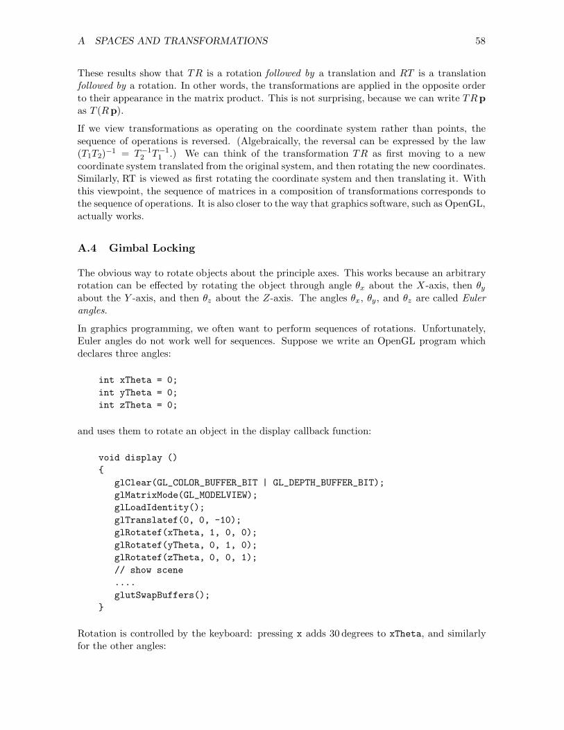
A SPACES AND TRANSFORMATIONS 58
These results show that TR is a rotation followed by a translation and RT is a translationfollowed by a rotation. In other words, the transformations are applied in the opposite orderto their appearance in the matrix product. This is not surprising, because we can write TRpas T (Rp).
If we view transformations as operating on the coordinate system rather than points, thesequence of operations is reversed. (Algebraically, the reversal can be expressed by the law(T1T2)−1 = T−1
2 T−11 .) We can think of the transformation TR as first moving to a new
coordinate system translated from the original system, and then rotating the new coordinates.Similarly, RT is viewed as first rotating the coordinate system and then translating it. Withthis viewpoint, the sequence of matrices in a composition of transformations corresponds tothe sequence of operations. It is also closer to the way that graphics software, such as OpenGL,actually works.
A.4 Gimbal Locking
The obvious way to rotate objects about the principle axes. This works because an arbitraryrotation can be effected by rotating the object through angle θx about the X-axis, then θy
about the Y -axis, and then θz about the Z-axis. The angles θx, θy , and θz are called Eulerangles.
In graphics programming, we often want to perform sequences of rotations. Unfortunately,Euler angles do not work well for sequences. Suppose we write an OpenGL program whichdeclares three angles:
int xTheta = 0;int yTheta = 0;int zTheta = 0;
and uses them to rotate an object in the display callback function:
void display (){
glClear(GL_COLOR_BUFFER_BIT | GL_DEPTH_BUFFER_BIT);glMatrixMode(GL_MODELVIEW);glLoadIdentity();glTranslatef(0, 0, -10);glRotatef(xTheta, 1, 0, 0);glRotatef(yTheta, 0, 1, 0);glRotatef(zTheta, 0, 0, 1);// show scene....glutSwapBuffers();
}
Rotation is controlled by the keyboard: pressing x adds 30 degrees to xTheta, and similarlyfor the other angles:
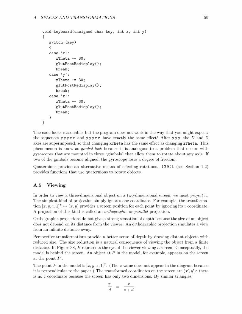
A SPACES AND TRANSFORMATIONS 59
void keyboard(unsigned char key, int x, int y){
switch (key){case ’x’:
xTheta += 30;glutPostRedisplay();break;
case ’y’:yTheta += 30;glutPostRedisplay();break;
case ’z’:zTheta += 30;glutPostRedisplay();break;
}}
The code looks reasonable, but the program does not work in the way that you might expect:the sequences y yy xx and y yy zz have exactly the same effect! After y yy, the X and Z
axes are superimposed, so that changing xTheta has the same effect as changing zTheta. Thisphenomenon is know as gimbal lock because it is analogous to a problem that occurs withgyroscopes that are mounted in three “gimbals” that allow them to rotate about any axis. Iftwo of the gimbals become aligned, the gyroscope loses a degree of freedom.
Quaternions provide an alternative means of effecting rotations. CUGL (see Section 1.2)provides functions that use quaternions to rotate objects.
A.5 Viewing
In order to view a three-dimensional object on a two-dimensional screen, we must project it.The simplest kind of projection simply ignores one coordinate. For example, the transforma-tion [x, y, z, 1]T 7→ (x, y) provides a screen position for each point by ignoring its z coordinate.A projection of this kind is called an orthographic or parallel projection.
Orthographic projections do not give a strong sensation of depth because the size of an objectdoes not depend on its distance from the viewer. An orthographic projection simulates a viewfrom an infinite distance away.
Perspective transformations provide a better sense of depth by drawing distant objects withreduced size. The size reduction is a natural consequence of viewing the object from a finitedistance. In Figure 38, E represents the eye of the viewer viewing a screen. Conceptually, themodel is behind the screen. An object at P in the model, for example, appears on the screenat the point P ′.
The point P in the model is [x, y, z, 1]T. (The x value does not appear in the diagram becauseit is perpendicular to the paper.) The transformed coordinates on the screen are (x′, y′): thereis no z coordinate because the screen has only two dimensions. By similar triangles:
x′
d=
x
z + d

A SPACES AND TRANSFORMATIONS 60
������������������������������
rr
r
� d - � z -?
y′6
?
y
6
E
P ′
Pscreen
Figure 38: Perspective transformation
y′
d=
y
z + d
and hence
x′ =x d
z + d
y′ =y d
z + d
To obtain the perspective transformation in matrix form, we note that
1 0 0 00 1 0 00 0 1 00 0 1/d 1
x
y
z
1
=
x
y
z
z/d + 1
Unlike the previous points we have seen, the transformed point has a fourth coordinate that
is not equal to 1. Homogenizing this point gives[
x d
z + d,
y d
z + d,
z d
z + d, 1]T
, as we obtained
above.
The z component has no obvious physical significance but there are advantages in retainingit. Since transformed z values depend monotonically on the original z values, the transformedvalues can be used for hidden surface elimination. Moreover, the transformation can beinverted only if the z information is retained. This is necessary for transforming normalvectors and for selecting objects from a scene.

B THEORY OF ILLUMINATION 61
B Theory of Illumination
To obtain realistic images in computer graphics, we need to know not only about light butalso what happens when light is reflected from an object into our eyes. The nature of thisreflection determines the appearance of the object. The general problem is to compute theapparent colour at each pixel that corresponds to part of the object on the screen.
B.1 Steps to Realistic Illumination
We provide various techniques for solving this problem, increasing the realism at each step. Ineach case, we define the intensity , I , of a pixel in terms of a formula. The first few techniquesignore colour.
Technique #1. We assume that each object has an intrinsic brightness ki. Then
I = ki
This technique can be used for simple graphics, but it is clearly unsatisfactory. There is noattempt to model properties of the light or its effect on the objects.
Technique #2. We assume that there is ambient light (light from all directions) withintensity Ia and that each object has an ambient reflection coefficient ka. This gives
I = Ia ka
In practice, the effect of technique #2 is very similar to that of technique #1.
Technique #3. We assume that there is a single, point source of light and that the objecthas diffuse or Lambertian reflective properties. This means that the light reflected from theobject depends only on the incidence angle of the light, not the direction of the viewer.
More precisely, suppose that: N is a vector normal to the surface of the object; L is a vectorcorresponding to the direction of the light; and V is a vector corresponding to the direction ofthe viewer. Figure 39 shows these vectors: note that V is not necessarily in the plane definedby L and N. Assume that all vectors are normalized (‖N‖ = ‖L‖ = ‖V‖ = 1). Then theapparent brightness of the object is proportional to N ·L. Note that:
• V does not appear in this expression and so the brightness does not depend on theviewer’s position;
• the brightness is greatest when N and L are parallel (N · L = 1); and
• the brightness is smallest when N and L are orthogonal (N · L = 0).
We can account for Lambertian reflection in the following way. Suppose that the beam oflight has cross-section area A and it strikes the surface of the object at an angle θ. Then thearea illuminated is approximately A/ cos θ. After striking the object, the light is scattereduniformly in all directions. The apparent brightness to the viewer is inversely proportional to
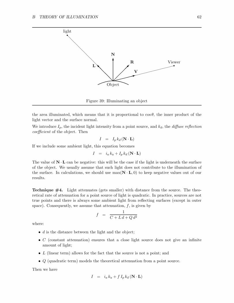
B THEORY OF ILLUMINATION 62
6
N
@@
@@@IL
��
����
R
������:V
@@
@@
@@
@@
@@
@@rlight
����������������rViewer
Object
Figure 39: Illuminating an object
the area illuminated, which means that it is proportional to cos θ, the inner product of thelight vector and the surface normal.
We introduce Ip, the incident light intensity from a point source, and kd, the diffuse reflectioncoefficient of the object. Then
I = Ip kd (N · L)
If we include some ambient light, this equation becomes
I = ia ka + Ip kd (N · L)
The value of N ·L can be negative: this will be the case if the light is underneath the surfaceof the object. We usually assume that such light does not contribute to the illumination ofthe surface. In calculations, we should use max(N · L, 0) to keep negative values out of ourresults.
Technique #4. Light attenuates (gets smaller) with distance from the source. The theo-retical rate of attenuation for a point source of light is quadratic. In practice, sources are nottrue points and there is always some ambient light from reflecting surfaces (except in outerspace). Consequently, we assume that attenuation, f , is given by
f =1
C + L d + Q d2
where:
• d is the distance between the light and the object;
• C (constant attenuation) ensures that a close light source does not give an infiniteamount of light;
• L (linear term) allows for the fact that the source is not a point; and
• Q (quadratic term) models the theoretical attenuation from a point source.
Then we have
I = ia ka + f Ip kd (N ·L)

B THEORY OF ILLUMINATION 63
Technique #5. Techniques #1 through #4 ignore colour. We assume that:
• the object has diffuse colour factors Odr, Odg, and Odb;
• the light has intensity colour factors corresponding to ambient sources (Iar, Iag, andIab); and
• point sources (Ipr, Ipg, and Ipb).
All of these numbers are in the range [0, 1]. We now have three intensity equations of theform
Iλ = Iaλ ka Odλ + f Ipλ kd Odλ (N · L)
for λ = r, g, b.
Technique #6. Lambertian reflection is a property of dull objects such as cloth or chalk.Many objects exhibit degrees of shininess: polished wood has some shininess and a mirror is theultimate in shininess. The technical name for shininess is specular reflection. A characteristicfeature of specular reflection is that it has a colour closer to the colour of the light sourcethan the colour of the object. For example, a brown table made of polished wood that isilluminated by a white light will have specular highlights that are white, not brown.
Specular reflection depends on the direction of the viewer as well as the light. We introducea new vector, R (the reflection vector), which is the direction in which the light would bereflected if the object was a mirror (see Figure 39). The brightness of specular reflection de-pends on the angle between R and V (the angle of the viewer). For Phong shading (developedby Phong Bui-Tong), we assume that the brightness is proportional to (R ·V)n, where n = 1corresponds to a slightly glossy surface and n = ∞ corresponds to a perfect mirror. We nowhave
Iλ = Iaλ ka Odλ + f Ipλ(kdOdλ (N · L) + ks (R ·V)n)
where ks is the specular reflection coefficient and n is the specular reflection exponent .
Technique #7. In practice, the colour of specular reflection is not completely independentof the colour of the object. To allow for this, we can give the object a specular colour Osλ.Then we have
Iλ = Iaλ ka Odλ + f Ipλ(kdOdλ (N ·L) + ks Osλ (R ·V)n)
This equation represents our final technique for lighting an object and is a close approximationto what OpenGL actually does. The actual calculation performed by OpenGL is:
Vλ = Oeλ + MaλOaλ +n−1∑
i=0
(1
kc + kld + kqd2
)
i
si [IaλOaλ + (N · L)IdλOdλ + (R ·V)σIsλOsλ]i

B THEORY OF ILLUMINATION 64
where
Vλ = Vertex brightnessMaλ = Ambient light model
kc = Constant attenuation coefficientkl = Linear attenuation coefficientkq = Quadratic attenuation coefficientd = Distance of light source from vertexsi = Spotlight effect
Iaλ = Ambient lightIdλ = Diffuse lightIsλ = Specular lightOeλ = Emissive brightness of materialOaλ = Ambient brightness of materialOdλ = Diffuse brightness of materialOsλ = Specular brightness of material
σ = Shininess of material
the subscript λ indicates colour components and the subscript i denotes one of the lights.
B.2 Multiple Light Sources
If there are several light sources, we simply add their contributions. If the sum of the con-tributions exceeds 1, we can either “clamp” the value (that is, use 1 instead of the actualresult) or reduce all values in proportion so that the greatest value is 1. Clamping is cheapercomputationally and usually sufficient.
B.3 Polygon Shading
The objects in graphical models are usually defined as many small polygons, typically trianglesor rectangles. We must choose a suitable colour for each visible pixel of a polygon: this iscalled polygon shading .
Flat Shading In flat shading, we compute a vector normal to the polygon and use it tocompute the colour for every pixel of the polygon. The computation implicitly assumes that:
• the polygon is really flat (not an approximation to a curved surface);
• N · L is constant (the light source is infinitely far away); and
• N ·V is constant (the viewer is infinitely far away.)
Flat shading is efficient computationally but not very satisfactory: the edges of the polygonstend to be visible and we see a polyhedron rather than the surface we are trying to approx-imate. (The edges are even more visible than we might expect, due to the subjective Macheffect , which exaggerates a change of colour along a line.)

B THEORY OF ILLUMINATION 65
Smooth Shading In smooth shading, we compute normals at the vertices of the polygons,averaging over the polygons that meet at the vertex. If we are using polygons to approximatea smooth surface, these vectors approximate the true surface normals at the vertices. Wecompute the colour at each vertex and then colour the polygons by interpolating the coloursat interior pixels.
Gouraud Shading Gouraud shading is a form of smooth shading that uses a particularkind of interpolation for efficiency.
1. Compute the normal at each vertex of the polygon mesh. For analytical surfaces, suchas spheres and cones, we can compute the normals exactly. For surfaces approximatedby polygons, we use the average of the surface normals at each vertex.
2. Compute the light intensity for each colour at each vertex using a lighting model (e.g.,Technique #7 above).
3. Interpolate intensities along the edges of the polygons.
4. Interpolate intensities along scan lines within the polygons.
Phong Shading Phong shading is similar to Gouraud shading but interpolates the normalsrather than the intensities. Phong shading requires more computation than Gouraud shadingbut gives better results, especially for specular highlights.

C FUNCTION REFERENCE 66
C Function Reference
Each function of OpenGL is specified by a prototype and a brief explanation. The expla-nations are brief: you may find the suggested examples help you to understand them. Thespecifications follow some conventions, listed below.
• Function descriptions are in alphabetical sequence by name. The prefix (gl-, glu-, orglut-) is not cosidered to be part of the name for alphabetization.
• If a function has many arguments of the same type, the argument types are omittedfrom the prototype but specified in the explanation that follows it.
• A name of the form glname{234}{sifd}[v] describes several functions. The name ofa particular function is obtained by taking one character from each “set” {...} andoptionally adding the character enclosed in brackets [...].
The digit gives the number of arguments and the letter gives the type. The final “v”, ifpresent, says that there will be a single argument that is a pointer to an array.
When the function definition uses this form, the argument types are omitted becausethey must conform to the function name.
For example, the function referred to as glVertex() in these notes may be called with any ofthe following argument lists.
• Two shorts specifying X and Y positions:
glVertex2s(3, 4);
• Four doubles specifying X , Y , Z, and W values:
glVertex4d(1.0, 1.0, 5.0, 1.0);
• A pointer to an array of three floats:
glVertex3fv(ptr);
Function Definitions
void glutAddMenuEntry (char *label, int selection);
Add an entry to the current menu. The first argument is the text that the user will see andthe second argument is the integer that will be passed to the callback function when the userselects this entry.
C FUNCTION REFERENCE 67
See also
glutCreateMenu().
void glutAddSubMenu (char *label, int menu);
Add a sub-menu to the current menu. The first argument is the text that the user will seeand the second argument is an integer returned by glutCreateMenu().
See also
glutCreateMenu().
void glutAttachMenu (int button);
Associate the current menu with a mouse button. The value of the argument must be one ofGLUT_LEFT_BUTTON, GLUT_MIDDLE_BUTTON, or GLUT_RIGHT_BUTTON.
See also
glutCreateMenu().
void glBegin (GLenum mode);
Marks the beginning of a vertex data list. The permitted values of mode are given in Table 3on page 17.
See also
glEnd().
void glutBitmapCharacter (void *font, int character);
Displays one bitmapped character at the current raster position and moves the raster positionright by the width of the character. Table 10 lists the permitted values of font.
See also
glRasterPos(), glutStrokeCharacter().
int glutBitmapWidth(void *font, int character);
Returns the width of the bitmapped character. Table 10 lists the permitted values of font.
void glClear (GLbitfield mask);
Clears the specified buffers. Table 11 shows the names of the mask bits. Using multiple callsof glClear() may be less efficient than using | to “OR” mask bits.

C FUNCTION REFERENCE 68
Font name DescriptionGLUT_BITMAP_8_BY_13 fixed width, 8 × 13 pixelsGLUT_BITMAP_9_BY_15 fixed width, 9 × 15 pixelsGLUT_BITMAP_TIMES_ROMAN_10 proportional width, 10 pointsGLUT_BITMAP_TIMES_ROMAN_24 proportional width, 24 pointsGLUT_BITMAP_HELVETICA_10 proportional width, 10 pointsGLUT_BITMAP_HELVETICA_12 proportional width, 12 pointsGLUT_BITMAP_HELVETICA_18 proportional width, 18 points
Table 10: Fonts for glutBitmapCharacter()
Buffer Mask bitColour GL COLOR BUFFER BIT
Depth GL DEPTH BUFFER BIT
Accumulation GL ACCUM BUFFER BIT
Stencil GL STENCIL BUFFER BIT
Table 11: Mask bits for clearing
void glClearColor (red, green, blue, alpha);
Set the clearing colour used for clearing the colour buffers in RGBA mode. The argumentsare all of type GLfloat and they are clamped to the range [0, 1]. Use this function to set thebackground colour of your scene.
Default
void glClearColor (0.0, 0.0, 0.0, 0.0);
void glColor{34}{sifd}[v] (...);
Set the current colour. The first three values give the intensities for red, green, and blue,respectively. The fourth argument, if present, gives the value of alpha to be used for blending.If v is present, there is one argument that points to an array. The values of all argumentsshould be in the range [0, 1].
Calls to glColor() have no effect if lighting is enabled.
int glutCreateMenu (void (*func)(int selection));
Create a menu and register a callback function that will be invoked when the user makesa selection from the menu. The value returned is an integer that identifies the menu. It isused as an argument to glutCreateSubMenu(), telling the submenu which menu it belongsto. The value passed to the callback function is an integer corresponding to the item selectedfrom the menu by the user.
C FUNCTION REFERENCE 69
See also
glutAddMenuEntry(), glutAddSubMenu(), glutAttachMenu().
int glutCreateSubWindow (win, x, y, width, height);
All arguments are integers. win is the number of the new window’s parent. (x,y) is thelocation of the new window relative to the parent window’s origin. width and height arethe width and height of the new window. The value returned is an integer that identifies thewindow.
int glutCreateWindow (const char * text);
Creates a window with features that have been previously defined by calls to the initializationfunctions glutInitDisplayMode(), glutInitWindowPosition(), and glutInitWindowSize().The string text will appear in the title bar at the top of the window. The window is notactually displayed on the screen until glutMainLoop() has been entered.
The value returned is a unique identifier for the window. It is used by programs that supportseveral graphics windows.
Call glutCreateWindow() before calling glEnable() to turn on special GL features.
See also
glutSetWindowTitle().
void glutDestroyWindow(int win);
Destroy the window with number win.
void glDisable (GLenum capability);
Turns off one of GL’s capabilities.
See also
glEnable().
void glutDisplayFunc (void (*func)(void));
Register a callback function that displays the model in the graphics window. The displayfunction has no arguments and does not return a value.
See also
glutPostRedisplay().
void glEnable (GLenum capability);
Turns on one of GL’s capabilities. There are many capabilities, including GL_DEPTH_TEST,GL_FOG, and so on.

C FUNCTION REFERENCE 70
See also
glDisable().
void glEnd();
Marks the end of a vertex data list introduced by glBegin();.
char *gluErrorString (int code);
Return a string describing the error indicated by code.
See also
glGetError();
void glFlush (void);
Forces previously issued OpenGL commands to begin execution. It is not usually necessaryto call glFlush() for programs run on a single-user system, but it is important for programsthat run on a network.
void glFrustum (left, right, bottom, top, near, far);
Defines a projection matrix and multiplies the current projection matrix by it. The matrixdefines a “viewing volume” for a perspective view in the negative Z direction.
All arguments should be GLfloats and far > near > 0. The first four arguments determinethe size of the viewing “window”. Only objects whose distance from the viewpoint is betweennear and far will be drawn.
See Also
gluPerspective(), glOrtho().
void glutFullScreen();
Request that the current window be displayed in full screen mode. The precise effect dependson the underlying window system, but the intent of this call is to maximize the window areaand to remove as much border decoration as possible.
A call to glutPositionWindow() or glutReshapeWindow() is supposed to reverse the effectof a call to glutFullScreen() but this doesn’t work on some Windows systems.
int glutGet(GLenum state);
Return the value of a GLUT state variable. There are many possible values of the parameterstate; Table 12 shows a few of the more useful ones.

C FUNCTION REFERENCE 71
Value of state Value returnedGLUT_WINDOW_X Distance from left of screen to left of current window
(pixels)GLUT_WINDOW_Y Distance from top of screen to to of current window
(pixels)GLUT_WINDOW_WIDTH Width of current window (pixels)GLUT_WINDOW_HEIGHT Height of current window (pixels)GLUT_SCREEN_WIDTH Width of the screen in pixels, zero if unknownGLUT_SCREEN_HEIGHT Height of the screen in pixels, zero if unknownGLUT_WINDOW_BUFFER_SIZE Number of bits used to store the current window’s colour
bufferGLUT_WINDOW_DOUBLEBUFFER 1 if double-buffering is enabled for the current window,
0 otherwiseGLUT_WINDOW_PARENT Window number of the current window’s parentGLUT_ELAPSED_TIME Time since glutInit was calledInvalid constant −1
Table 12: Parameter values for glutGet(state)
int glGetError (void);
Return the value of the error flag. If the result is GL_NO_ERROR, then no error has oc-curred. Otherwise, you can obtain a string describing the error by passing the result togluErrorString().
int glutGetModifiers();
If this function is called while a keyboard, special, or mouse callback is being handled, itreturns a bit string giving the state of the keyboard, as follows:
Bit set Meaning
GLUT_ACTIVE_SHIFT A Shift key is pressed or Caps Lock is activeGLUT_ACTIVE_CTRL A Control key is pressedGLUT_ACTIVE_ALT An Alt key is pressed
See also:
glutKeyboardFunc(), glutKeyboardFunc().
int glutGetWindow(void);
Return the value of the current window. All functions that apply to windows operate onthe current window. Events (such as mouse clicks and keystrokes) apply to the window thatcontains the cursor, not necessarily the current window. The value of win is the integerreturned by a call to glutCreateWindow().

C FUNCTION REFERENCE 72
Mode bit DescriptionGLUT_RGB Use RGB colour values (default)GLUT_RGBA Use RGB colour values (same as GLUT_RGB)GLUT_INDEX Use colour indexesGLUT_SINGLE Use a single colour buffer (default)GLUT_DOUBLE Use two colour buffersGLUT_DEPTH Use a depth bufferGLUT_STENCIL Use a stencil bufferGLUT_ALPHA Use a buffer with an alpha componentGLUT_STEREO Use a stereo pair of windowsGLUT_ACCUM Use an accumulation buffer
Table 13: Display mode bits
See also
glutSetWindow(), glutCreateWindow().
void glutIdleFunc (void (*func)(void));
Register a callback function that will be called when no other events are being processed.
void glutInit (int argc, char *argv[]);
Initialize the GLUT library. This function should be called before any other glut- functions.The arguments have the same type as the arguments of main() and are, by convention, thesame as the arguments passed to main().
void glutInitDisplayMode (unsigned int mode);
Specify a display mode. The argument is a bitfield constructed from constants chosen fromTable 13 and OR’d together.
Default
glutInitDisplayMode (GLUT_RGBA | GLUT_SINGLE | GLUT_DEPTH);
void glutInitWindowPosition (int x, int y);
Sets the initial position of the graphics window to be created by glutCreateWindow(). Thearguments give the position of the top left corner of the window in screen coordinates (Y = 0 atthe top of the screen). If you do not call this function, or you call it with negative arguments,the underlying window system chooses the window position.
Default
glutWindowPosition (-1, -1);

C FUNCTION REFERENCE 73
void glutInitWindowSize (int width, int height);
Sets the initial size of the graphics window that is to be created by glutCreateWindow().The arguments give the size of the window in pixels.
Default
glutInitWindowSize (300, 300);
See also
glutReshapeFunc().
void glutKeyboardFunc (void (*func)(key, x, y));
Register a callback function that handles keyboard events. The arguments passed to thefunction are the unsigned char code of the key that was pressed, and the current position ofthe mouse.
See also
glutSpecialFunc(), glutGetModifiers().
void glLight{if}[v] (GLenum light, GLenum name, GLfloat values);
Creates the specified light if it has not already been created and defines some of its properties.The first argument must be GL_LIGHTn, where n = 0, 1, 2, . . . , 7. The second argument is aparameter name, and should be one of:
GL_AMBIENT GL_SPOT_DIRECTION GL_CONSTANT_ATTENUATIONGL_DIFFUSE GL_SPOT_EXPONENT GL_LINEAR_ATTENUATIONGL_SPECULAR GL_SPOT_CUTOFF GL_QUADRATIC_ATTENUATIONGL_POSITION
The third argument gives the value of the parameter. The most common form of call isglLightfv, in which case the third argument is a pointer to an array of four GLfloats. SeeTable 7 on page 40 for an explanation of the parameter names and values.
Default
Figure 40 shows default values for lighting.
void glLightModel{if}[v] (GLenum name, GLfloat [*] value);
Define properties of the lighting model. The first argument is a parameter name, and it shouldbe one of:
GL_LIGHT_MODEL_AMBIENTGL_LIGHT_MODEL_LOCAL_VIEWGL_LIGHT_MODEL_TWO_SIDE
See Table 8 on page 41 for an explanation of the meanings of these parameters and theirvalues.

C FUNCTION REFERENCE 74
GLfloat black[] = { 0.0, 0.0, 0.0, 1.0 };GLfloat white[] = { 1.0, 1.0, 1.0, 1.0 };GLfloat pos[] = { 0.0, 0.0, 1.0, 0.0 };GLfloat dir[] = { 0.0, 0.0, -1.0 };glLightfv(GL_LIGHT0, GL_AMBIENT, black);glLightfv(GL_LIGHT0, GL_DIFFUSE, white);glLightfv(GL_LIGHT0, GL_SPECULAR, white);glLightfv(GL_LIGHT0, GL_POSITION, pos);glLightfv(GL_LIGHT0, GL_SPOT_DIRECTION, dir);glLightf(GL_LIGHT0, GL_SPOT_EXPONENT, 0.0);glLightf(GL_LIGHT0, GL_SPOT_CUTOFF, 180.0);glLightf(GL_LIGHT0, GL_CONSTANT_ATTENUATION, 1.0);glLightf(GL_LIGHT0, GL_LINEAR_ATTENUATION, 0.0);glLightf(GL_LIGHT0, GL_QUADRATIC_ATTENUATION, 0.0);
Figure 40: Default values for lighting
Default
GLfloat amb[] = { 0.2, 0.2, 0.2, 1.0 };glLightModelfv(GL_LIGHT_MODEL_AMBIENT, amb);glLightModelf(GL_LIGHT_MODEL_LOCAL_VIEWER, GL_FALSE);glLightModelf(GL_LIGHT_MODEL_TWO_SIDE, GL_FALSE);
void glLineWidth (GLfloat width);
Sets the width of lines. The default value of width is 1.0, and its value must be greater than0.0.
void gluLookAt (ex, ey, ez, cx, cy, cz, ux, uy, uz);
Defines a viewing matrix and multiplies it to the right of the current GL_MODELVIEW matrix.All of the arguments have type GLfloat.
The matrix establishes a point of view for looking at the scene. Your “eye” is at (ex, ey, ez)and you are looking towards the point (cx, cy, cz). The vector (ux, uy, uz) is pointing upwards.
void glLoadIdentity (void);
Sets the current matrix (top of the stack) to the identity matrix.
void glutMainLoop (void);
Enters the GLUT processing loop. Within this loop, events are processed and the correspond-ing callback functions are invoked. This function never returns: the program is terminatedby executing exit() or by the user closing the graphics window.

C FUNCTION REFERENCE 75
glMaterial{if}[v] (GLenum face, GLenum name, GLfloat[*] value);
Defines a material property for use in lighting. The first argument specifies which face of eachpolygon is being defined. The allowed values are GL_FRONT, GL_BACK, and GL_FRONT_AND_BACK.You are allowed to call glMaterial() twice, with different values for front and back polygons.Back faces will not be rendered unless you request GL_LIGHT_MODEL_TWO_SIDE when you callglLightModel().
The second argument is the name of a parameter and the third argument is the correspondingvalue. When v is included in the function name, the third argument should be a pointer to anarray. See Table 6 on page 38 for an explanation of the parameter names and their meanings.
Default
GLfloat dim[] = { 0.2, 0.2, 0.2, 0.8 };GLfloat bright[] = { 0.8, 0.8, 0.8, 1.0 };GLfloat black[] = { 0.0, 0.0, 0.0, 1.0 };GLfloat shine[] = { 0.0 };glMaterialfv(GL_FRONT_AND_BACK, GL_AMBIENT, dim);glMaterialfv(GL_FRONT_AND_BACK, GL_DIFFUSE, bright);glMaterialfv(GL_FRONT_AND_BACK, GL_SPECULAR, black);glMaterialfv(GL_FRONT_AND_BACK, GL_SHININESS, shine);glMaterialfv(GL_FRONT_AND_BACK, GL_EMISSION, black);
void glMatrixMode (GLenum mode);
Sets the matrix mode to one of GL_MODELVIEW (default), GL_PROJECTION, or GL_TEXTURE.
void glutMotionFunc (void (*func)(int x, int y));
Register a callback function for mouse movements. The function is called when the mouse isdragged with one of its buttons pressed, and it is given the current mouse coordinates.
See also
glutPassiveMotionFunc().
void glutMouseFunc (void (*func)(button, state, x, y));
Register a callback function that handles mouse events. The callback function must take fourarguments, all of type int: a mouse button (one of GLUT_LEFT_BUTTON, GLUT_MIDDLE_BUTTON,or GLUT_RIGHT_BUTTON); the state of the button (either GLUT_UP or GLUT_DOWN); and thecurrent position of the mouse.
void glNormal3{bsidf}(nx, ny, nz);void glNormal3{bsidf}v(p);
Defines a normal vector for the current vertex. In the first form, the user provides the valuesof the components. In the second form, the user provides a pointer to an array containing thevalues of the components.

C FUNCTION REFERENCE 76
void glOrtho (left, right, bottom, top, near, far);
Defines an orthographic projection matrix with viewing volume bounded by (x, y, z) whereleft ≤ x ≤ right, bottom ≤ y ≤ top, and near ≤ −z ≤ far. The arguments are of typeGLfloat.
void glOrtho2D (left, right, bottom, top);
This function is used mainly for two-dimensional graphics. The call
glOrtho2D (left, right, bottom, top);
is equivalent to
glOrtho (left, right, bottom, top, -1.0, 1.0);
void glutPassiveMotionFunc (void (*func)(int x, int y));
Register a callback function for mouse movements. The function is called when the mouse isdragged without any buttons pressed, and it is given the current mouse coordinates.
void gluPerspective (alpha, aspect, near, far);
Defines a projection matrix and multiplies the current projection matrix by it. All argumentsare GLfloats. The camera is situated at the origin and is looking in the negative Z direction.alpha is the vertical angle of the field of view in degrees: it must be positive and less than180◦. A typical value is 28◦, corresponding to a 50mm lens on a 35mm camera. aspect is theaspect ratio (width/height) of the image. Only objects whose distance from the viewpoint isbetween near and far (near ≤ −z ≤ far) will be drawn.
See also
glFrustum(), glOrtho().
void glPointSize (GLfloat size);
Sets the size of a point. The default value of size is 1.0 and its value must be greater than 0.
void glPolygonMode (GLenum face, GLenum mode);
Controls the drawing mode for a polygon’s front and back faces. The value of face maybe GL_FRONT, GL_BACK, or GL_FRONT_AND_BACK. The value of mode may be GL_POINT (drawvertexes), GL_LINES (draw edges), or GL_FILL (draw filled polygon).
Default
glPolygonMode (FRONT_AND_BACK, GL_FILL);

C FUNCTION REFERENCE 77
void glPopMatrix (void);
Pops the top matrix of the current matrix stack. The value of the popped matrix is lost.
See also
glPushMatrix().
void glutPositionWindow(int x, int y);
Request that the current window be moved so that its top left corner is at (x, y).
void glutPostRedisplay (void);
Requests that the current graphics window be redrawn at the next opportunity: glutMainLoop()will eventually invoke the callback function registered by glutDisplayFunc().
void glPushMatrix (void);
Makes a copy of the current transformation matrix and pushes it onto the stack.
See also
glPopMatrix(), glLoadIdentity().
void glRasterPos{234}{sifd}[v] (x, y, z, w);
Set the current raster position. The arguments are used in the same way as the coordinates of avertex (that is, transformations are applied). This function is typically used before displayinga bitmap or bitmapped character.
See also
glutBitmapCharacter().
void glRect{sifd}[v] (x0, y0, x1, y1);
Draw a rectangle with top left corner at (x0, y0) and bottom right corner (x1, y1). Therectangle is in the plane z = 0 and is drawn according to the current polygon drawing style.The current transformation is applied to the coordinates.
See also
glPolygonMode().
void glutReshapeFunc (void (*func)(int width, int height));
Register a callback function that adjusts the display after the graphics window has been movedor resized. The reshape function must accept two arguments, the new width and new heightof the window in pixels, and does not return a value.

C FUNCTION REFERENCE 78
Default
void default_reshape (int width, int height){
glViewport(0, 0, width, height);}
void glutReshapeWindow(int w, int h);
Request that the shape of the current window be changed so that its width is w and its newheight is h.
glRotate{fd} (angle, x, y, z);
Multiples the current matrix by a matrix that rotates counterclockwise through the givenangle. The axis of rotation is a line from the origin (0, 0, 0) to the point (x, y, z).
void glScale{fd} (x, y, z);
Multiples the current matrix by a matrix that stretches or shrinks an object along each axis.The object will be distorted if the arguments are not equal. The arguments may be positiveor negative. If an argument is −1, the object is reflected in the corresponding axis.
void glutSetCursor (int style);
Change the cursor image in the current window. The value of style determines the shape ofthe cursor; Table 14 shows some of the possibilities.
void glutSetWindow(int win);
Set the current window to be win. All functions that apply to windows operate on the currentwindow. Events (such as mouse clicks and keystrokes) apply to the window that contains thecursor, not necessarily the current window. The value of win is the integer returned by a callto glutCreateWindow().
See also
glutGetWindow(), glutCreateWindow().
void glutSetWindowTitle(const char * text);
Write text in the current window title bar.
void glShadeModel (GLenum mode);
Sets the shading model to either GL_SMOOTH (default) or GL_FLAT.

C FUNCTION REFERENCE 79
Identifier DescriptionGLUT_CURSOR_LEFT_ARROW left arrowGLUT_CURSOR_RIGHT_ARROW right arrowGLUT_CURSOR_TOP_SIDE arrow pointing to top of windowGLUT_CURSOR_BOTTOM_SIDE arrow pointing to bottom of windowGLUT_CURSOR_LEFT_SIDE arrow pointing to left side of windowGLUT_CURSOR_RIGHT_SIDE arrow pointing to right side of windowGLUT_CURSOR_CURSOR_INFO pointing handGLUT_CURSOR_DESTROY skull and crossbonesGLUT_CURSOR_HELP question markGLUT_CURSOR_CYCLE rotating arrowsGLUT_CURSOR_SPRAY spray canGLUT_CURSOR_WAIT wrist watchGLUT_CURSOR_TEXT text insertion markerGLUT_CURSOR_CROSSHAIR small cross hairGLUT_CURSOR_FULL_CROSS_HAIR full window cross hairGLUT_CURSOR_NONE invisible cursor
Table 14: Cursor codes
void glutSpecialFunc (void (*func)(int key, int x, int y));
Registers a callback function for special key codes, such as arrows, F keys, and so on. Thecallback parameters x and y give the position of the mouse when the key was pressed. Notethat the keys esc, backspace, and delete have regular ASCII codes and are recognized byglutKeyboardFunc().
The keys are identified by predefined constants: see Table 2 on page 12.
See also
glutKeyboardFunc() glutGetModifiers().
void glutStrokeCharacter (void *font, int character);
Draws a stroked character at the origin of the current model view and advance the model viewmatrix by the width of the character. Stroked characters may be (and usually are) scaled.There are two fonts available:
GLUT STROKE ROMAN. A proportionally spaced Roman font for ASCII characters 32 through127. All characters sit on a base line and reach up to 119.05 units above and 33.33 unitsbelow the line.
GLUT MONO ROMAN. A fixed-space Roman font for ASCII characters 32 through 127. All char-acters sit on a base line and reach up to 119.05 units above and 33.33 units below theline. Each character is 104.76 units wide.

C FUNCTION REFERENCE 80
See also
glutBitmapCharacter(), glutStrokeWidth().
int glutStrokeWidth (void *font, int character);
Return the width of the given character. The font must be a stroked font.
void glutSwapBuffers (void);
Exchange the “front” colour buffer and the “back” colour buffer. OpenGL displays the frontbuffer while the program is drawing into the back buffer. This works only if the modeGLUT_DOUBLE was selected in the call to glutInitDisplayMode().
void glTranslate{fd} (x, y, z);
Multiples the current matrix by a matrix that translates (moves) an object from (X, Y, Z) to(X + x, Y + y, Z + z).
void glVertex{234}{sifd} (x, y, z, w);void glVertex{234}v (p);
Specifies a vertex. Up to four coordinates (x, y, z, and w) may be provided. z defaults to 0and w defaults to 1. In the first form, the user provides the coordinates as arguments. In thesecond form, the user provides a pointer to an array containing the coordinates.
void glViewport (x, y, width, height);
Defines a pixel rectangle in the viewing window into which the final image is to be mapped.The arguments are integers. The lower-left corner of the viewport is at (x, y) and the viewporthas the indicated width and height. The default viewport is the entire viewing window.