Getting Started Guide - Cisco Aironet 2800 Series Access...
50
GETTING STARTED GUIDE Cisco Aironet 2800 Series Access Points First Published: June 22, 2016
Transcript of Getting Started Guide - Cisco Aironet 2800 Series Access...

GETTING STARTED GUIDE
Cisco Aironet 2800 Series Access Points
First Published: June 22, 2016
1 About this Guide
2 About the Access Point
3 Safety Instructions
4 Unpacking
5 AP Views, Ports, and Connectors
6 Preparing the AP for Installation
7 Installation Overview
8 Performing a Pre-Installation Configuration
9 Mounting and Grounding the Access Point
10 Powering the Access Point
11 Configuring and Deploying the Access Point
12 Checking the Access Point LEDs
13 Miscellaneous Usage and Configuration Guidelines
15 Related Documentation
16 Declarations of Conformity and Regulatory Information
17 Obtaining Documentation and Submitting a Service Request
2
1 About this GuideThis guide provides instructions on how to install your Cisco Aironet 2800I and 2800E series access points and provides links to resources which can help you configure the access point. This guide provides mounting instructions and limited troubleshooting procedures.
The 2800 series access point is referred to as access point or AP in this document.
2 About the Access PointThe Cisco Aironet 2800 Series Wi-Fi access points provide 802.11ac Wave 2 with Multi User MIMO (MU MIMO). This AP series offers integrated and external antenna options, with a dedicated 5 GHz radio and a flexible radio that can be configured as a 2.4 GHz radio (default) or as an additional 5 GHz radio. This access point supports a greater overall High Density Experience (HDX) which provides mission-critical wireless to meet your performance needs. The access points support full interoperability with leading 802.11ac clients, and support a mixed deployment with other access points and controllers.
A full listing of the access point's features and specifications are provided in the Cisco Aironet 2800 Series Access Point Data Sheet, at the following URL:
http://www.cisco.com/c/en/us/products/collateral/wireless/aironet-2800-series-access-points/datasheet-c78-736497.html
Access Point FeaturesThe 2800 series access point is a wireless controller-based product and supports:
• Integrated antennas on the 2802I access point model (AIR-AP2802I-x-K9)
• External antennas on the 2802E access point models (AIR-AP2802E-x-K9)
Note The ‘x’ in the model numbers represents the regulatory domain. For information on supported regulatory domains, see the“AP Model Numbers and Regulatory Domains” section on page 4.
• Flexible Radio Assignment, allowing for either manual configuration or for the APs to intelligently determine the operating role of the integrated radios based on the available RF environment. The AP can operate in the following modes:
– 2.4 GHz and 5 GHz role, where one radio serves clients in 2.4 GHz mode, while the other serves clients in 5 GHz mode.
3
– Dual 5 GHz radio role, with both radios operating in the 5 GHz band, actively serving client devices to maximize the benefits of 802.11ac Wave 2 and to increase client device capacity.
– Wireless Security Monitoring and 5 GHz role, where one radio serves 5 GHz clients, while the other radio scans both 2.4 GHz and 5 GHz for wIPS attackers, CleanAir interferers, and rogue devices.
• Multiuser Multiple-Input Multiple-Output (MU-MIMO) technology with 3 spatial streams.
• Cross-AP Noise Reduction, a Cisco innovation that enables APs to intelligently collaborate in real time about RF conditions so that users connect with optimized signal quality and performance.
• Optimized AP Roaming for ensuring that client devices associate with the AP in their coverage range that offers the fastest data rate available.
• Cisco ClientLink 4.0 technology for improved downlink performance to all mobile devices, including one-, two-, and three-spatial-stream devices up to 802.11ac Wave 1 and Wave 2. The technology also improves battery life on mobile devices.
• Cisco CleanAir technology enhanced with 160MHz channel support. CleanAir delivers proactive, high-speed spectrum intelligence across 20-, 40-, and 80-, and 160-MHz-wide channels to combat performance problems arising from wireless interference.
• MIMO equalization capabilities, which optimize uplink performance and reliability by reducing the impact of signal fade.
The AP supports the following operating modes:
• Centralized
• Sniffer
• FlexConnect
• Monitor Mode
• Service Provider Option 60 (DHCP Option 60)
AP Model Numbers and Regulatory Domains
AP Type Model Number Details
Access Point for indoor environments, with internal antennas
AIR-AP2802I-x-K9 Dual-band, controller-based 802.11a/g/n/ac
Access Point for indoor environments, with external antennas
AIR-AP2802E-x-K9
4
You need to verify whether the AP model you have is approved for use in your country. To verify approval and to identify the regulatory domain that corresponds to a particular country, visit http://www.cisco.com/go/aironet/compliance. Not all regulatory domains have been approved. As and when they are approved, this compliance list will be updated.
Antennas and RadiosThe 2800 series access point contains a dedicated 5 GHz radio and a flexible radio that can be configured as a 2.4 GHz radio (default) or as an additional 5 GHz radio. The 2800 series access point configurations are:
• AIR-AP2802I-x-K9—One 2.4 GHz/5 GHz flexible radio and one 5 GHz radio.
• AIR-AP2802E-x-K9—One 2.4 GHz/5 GHz flexible radio and one 5 GHz radio. The are 4 dual-band dipole and a Smart antenna connector.
Internal Antennas
The 2802I has 12 cross polarized internal antennas.
External Antennas
The 2802E model is configured with up to four external dual-band dipole antennas, and two 2.4 GHz/ 5 GHz dual-band radios. The radio and antennas support frequency bands 2400–2500 MHz and 5180–5865 MHz through a common dual-band RF interface. Features of the external dual-band dipole antennas are:
• Four RTNC antenna connectors on the top of the access point
• Four TX/RX antennas
• Smart Antenna connector for connecting an external antenna
5
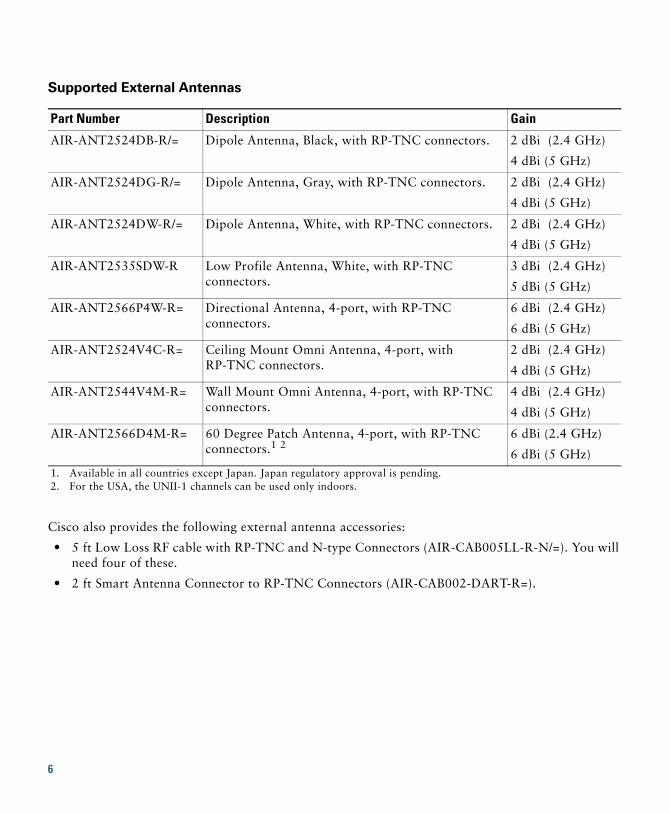
Supported External Antennas
Cisco also provides the following external antenna accessories:
• 5 ft Low Loss RF cable with RP-TNC and N-type Connectors (AIR-CAB005LL-R-N/=). You will need four of these.
• 2 ft Smart Antenna Connector to RP-TNC Connectors (AIR-CAB002-DART-R=).
Part Number Description Gain
AIR-ANT2524DB-R/= Dipole Antenna, Black, with RP-TNC connectors. 2 dBi (2.4 GHz)
4 dBi (5 GHz)
AIR-ANT2524DG-R/= Dipole Antenna, Gray, with RP-TNC connectors. 2 dBi (2.4 GHz)
4 dBi (5 GHz)
AIR-ANT2524DW-R/= Dipole Antenna, White, with RP-TNC connectors. 2 dBi (2.4 GHz)
4 dBi (5 GHz)
AIR-ANT2535SDW-R Low Profile Antenna, White, with RP-TNC connectors.
3 dBi (2.4 GHz)
5 dBi (5 GHz)
AIR-ANT2566P4W-R= Directional Antenna, 4-port, with RP-TNC connectors.
6 dBi (2.4 GHz)
6 dBi (5 GHz)
AIR-ANT2524V4C-R= Ceiling Mount Omni Antenna, 4-port, with RP-TNC connectors.
2 dBi (2.4 GHz)
4 dBi (5 GHz)
AIR-ANT2544V4M-R= Wall Mount Omni Antenna, 4-port, with RP-TNC connectors.
4 dBi (2.4 GHz)
4 dBi (5 GHz)
AIR-ANT2566D4M-R= 60 Degree Patch Antenna, 4-port, with RP-TNC connectors.1 2
1. Available in all countries except Japan. Japan regulatory approval is pending.2. For the USA, the UNII-1 channels can be used only indoors.
6 dBi (2.4 GHz)
6 dBi (5 GHz)
6
3 Safety InstructionsTranslated versions of the following safety warnings are provided in the translated safety warnings document that is shipped with your access point. The translated warnings are also in the Translated Safety Warnings for Cisco Aironet Access Points, which is available on Cisco.com.
Warning IMPORTANT SAFETY INSTRUCTIONS
This warning symbol means danger. You are in a situation that could cause bodily injury. Before you work on any equipment, be aware of the hazards involved with electrical circuitry and be familiar with standard practices for preventing accidents. Use the statement number provided at the end of each warning to locate its translation in the translated safety warnings that accompanied this device. Statement 1071
SAVE THESE INSTRUCTIONS
Warning Read the installation instructions before you connect the system to its power source. Statement 1004
Warning Installation of the equipment must comply with local and national electrical codes. Statement 1074
Warning This product relies on the building’s installation for short-circuit (overcurrent) protection. Ensure that the protective device is rated not greater than: 20A. Statement 1005
Warning Do not operate your wireless network device near unshielded blasting caps or in an explosive environment unless the device has been modified to be especially qualified for such use. Statement 245B
Warning In order to comply with FCC radio frequency (RF) exposure limits, antennas should be located at a minimum of 12 inches (30 cm) or more from the body of all persons. Statement 332
7
Caution The fasteners you use to mount an access point on a ceiling must be capable of maintaining a minimum pullout force of 20 lbs (9 kg) and must use all 4 indented holes on the mounting bracket.
Caution This product and all interconnected equipment must be installed indoors within the same building, including the associated LAN connections as defined by Environment A of the IEEE 802.af Standard.
Note The access point is suitable for use in environmental air space in accordance with section 300.22.C of the National Electrical Code and sections 2-128, 12-010(3), and 12-100 of the Canadian Electrical Code, Part 1, C22.1. You should not install the power supply or power injector in air handling spaces.
Note Use only with listed ITE equipment.
4 UnpackingTo unpack the access point, follow these steps:
Step 1 Unpack and remove the access point and the accessory kit from the shipping box.
Step 2 Return any packing material to the shipping container and save it for future use.
Step 3 Verify that you have received the items listed below. If any item is missing or damaged, contact your Cisco representative or reseller for instructions.
– The access point
– Mounting bracket (selected when you ordered the access point)
– Adjustable ceiling-rail clip (selected when you ordered the access point)
8
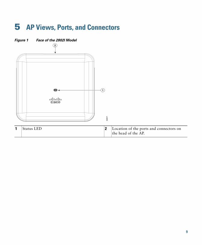
5 AP Views, Ports, and Connectors
Figure 1 Face of the 2802I Model
1 Status LED 2 Location of the ports and connectors on the head of the AP.
3545
71
1
2
9
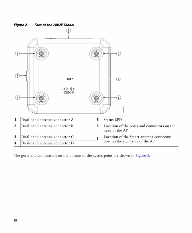
Figure 2 Face of the 2802E Model
The ports and connections on the bottom of the access point are shown in Figure 3.
1 Dual-band antenna connector A 5 Status LED
2 Dual-band antenna connector B 6 Location of the ports and connectors on the head of the AP
3 Dual-band antenna connector C 7 Location of the Smart antenna connector port on the right side of the AP4 Dual-band antenna connector D
3545
69
1
7
6
4
2
3
5
10
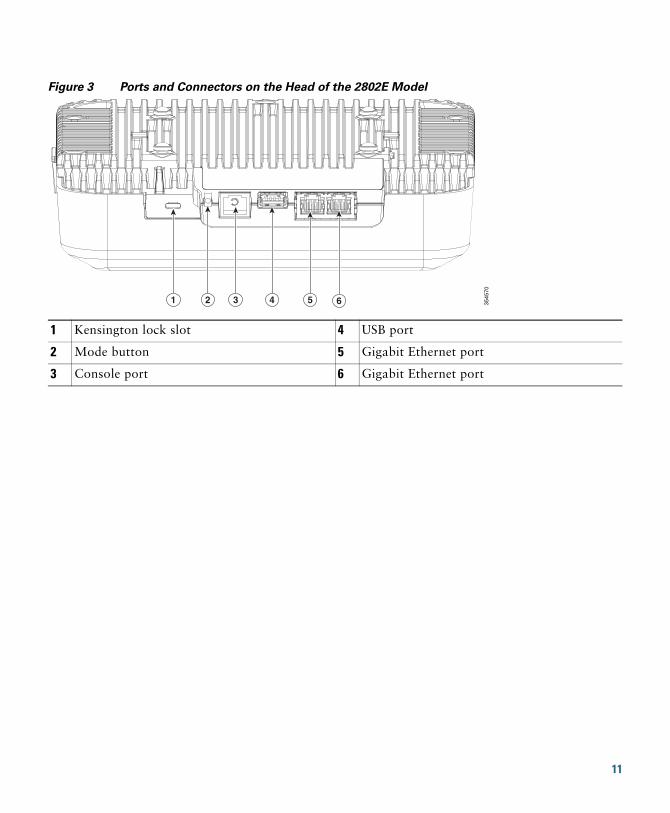
Figure 3 Ports and Connectors on the Head of the 2802E Model
1 Kensington lock slot 4 USB port
2 Mode button 5 Gigabit Ethernet port
3 Console port 6 Gigabit Ethernet port
3545
70
1 2 3 4 5 6
11
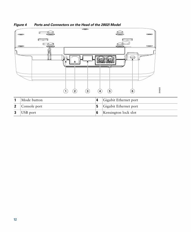
Figure 4 Ports and Connectors on the Head of the 2802I Model
1 Mode button 4 Gigabit Ethernet port
2 Console port 5 Gigabit Ethernet port
3 USB port 6 Kensington lock slot
3546
25
1 2 3 4 5 6
12
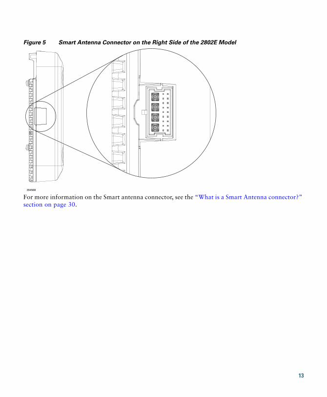
Figure 5 Smart Antenna Connector on the Right Side of the 2802E Model
For more information on the Smart antenna connector, see the “What is a Smart Antenna connector?” section on page 30.
354568
13
6 Preparing the AP for InstallationBefore you mount and deploy your access point, we recommend that you perform a site survey (or use the site planning tool) to determine the best location to install your access point.
You should have the following information about your wireless network available:
• Access point locations.
• Access point mounting options: below a suspended ceiling, on a flat horizontal surface, or on a desktop.
Note You can mount the access point above a suspended ceiling but you must purchase additional mounting hardware: See “Mounting and Grounding the Access Point” section on page 19 for additional information.
• Access point power options: PoE+ or Cisco Power Injector AIR-PWRINJ6=.
Cisco recommends that you make a site map showing access point locations so that you can record the device MAC addresses from each location and return them to the person who is planning or managing your wireless network.
7 Installation OverviewInstalling the access point involves these operations:
Step 1 Performing a Pre-Installation Configuration, page 15 (optional)
Step 2 Mounting and Grounding the Access Point, page 19
Step 3 Powering the Access Point, page 21
Step 4 Preparing the AP for Installation, page 14
14
8 Performing a Pre-Installation ConfigurationThe following procedures ensure that your access point installation and initial operation go as expected. This procedure is optional.
Note Performing a pre-installation configuration is an optional procedure. If your network controller is properly configured, you can install your access point in its final location and connect it to the network from there. See the “Deploying the Access Point on the Wireless Network” section on page 23 for details.
The following Pre-Installation Configuration procedure given does not include configuring Link Aggregation. For information on configuring Link Aggregation, see the Cisco Wireless LAN Controller Configuration Guide, Release 8.2, at this URL:
http://www.cisco.com/c/en/us/td/docs/wireless/controller/8-2/config-guide/b_cg82.html
The pre-installation configuration setup is illustrated in Figure 6.
15
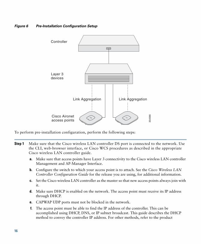
Figure 6 Pre-Installation Configuration Setup
To perform pre-installation configuration, perform the following steps:
Step 1 Make sure that the Cisco wireless LAN controller DS port is connected to the network. Use the CLI, web-browser interface, or Cisco WCS procedures as described in the appropriate Cisco wireless LAN controller guide.
a. Make sure that access points have Layer 3 connectivity to the Cisco wireless LAN controller Management and AP-Manager Interface.
b. Configure the switch to which your access point is to attach. See the Cisco Wireless LAN Controller Configuration Guide for the release you are using, for additional information.
c. Set the Cisco wireless LAN controller as the master so that new access points always join with it.
d. Make sure DHCP is enabled on the network. The access point must receive its IP address through DHCP.
e. CAPWAP UDP ports must not be blocked in the network.
f. The access point must be able to find the IP address of the controller. This can be accomplished using DHCP, DNS, or IP subnet broadcast. This guide describes the DHCP method to convey the controller IP address. For other methods, refer to the product
Controller
Layer 3devices
Cisco Aironetaccess points 35
4066
Link Aggregation Link Aggregation
16
documentation. See also the “Configuring DHCP Option 43” section on page 28 for more information.
Note The access point requires a gigabit Ethernet (GbE) link to prevent the Ethernet port from becoming a bottleneck for traffic because wireless traffic speeds exceed transmit speeds of a 10/100 Ethernet port.
Step 2 Apply power to the access point. See Powering the Access Point, page 21.
a. As the access point attempts to connect to the controller, the LEDs cycle through a green, red, and amber sequence, which can take up to 5 minutes.
Note If the access point remains in this mode for more than five minutes, the access point is unable to find the Master Cisco wireless LAN controller. Check the connection between the access point and the Cisco wireless LAN controller and be sure that they are on the same subnet.
b. If the access point shuts down, check the power source.
c. After the access point finds the Cisco wireless LAN controller, it attempts to download the new operating system code if the access point code version differs from the Cisco wireless LAN controller code version. While this is happening, the Status LED blinks amber.
d. If the operating system download is successful, the access point reboots.
Step 3 Configure the access point if required. Use the controller CLI, controller GUI, or Cisco Prime Infrastructure to customize the access-point-specific 802.11ac network settings.
Step 4 If the pre-installation configuration is successful, the Status LED is green indicating normal operation. Disconnect the access point and mount it at the location at which you intend to deploy it on the wireless network.
Step 5 If your access point does not indicate normal operation, turn it off and repeat the pre-installation configuration.
17
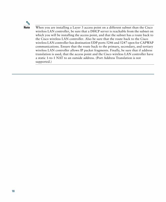
Note When you are installing a Layer 3 access point on a different subnet than the Cisco wireless LAN controller, be sure that a DHCP server is reachable from the subnet on which you will be installing the access point, and that the subnet has a route back to the Cisco wireless LAN controller. Also be sure that the route back to the Cisco wireless LAN controller has destination UDP ports 5246 and 5247 open for CAPWAP communications. Ensure that the route back to the primary, secondary, and tertiary wireless LAN controller allows IP packet fragments. Finally, be sure that if address translation is used, that the access point and the Cisco wireless LAN controller have a static 1-to-1 NAT to an outside address. (Port Address Translation is not supported.)
18
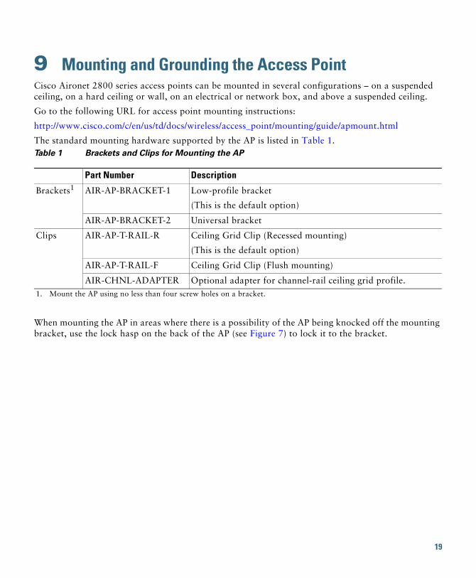
9 Mounting and Grounding the Access PointCisco Aironet 2800 series access points can be mounted in several configurations – on a suspended ceiling, on a hard ceiling or wall, on an electrical or network box, and above a suspended ceiling.
Go to the following URL for access point mounting instructions:
http://www.cisco.com/c/en/us/td/docs/wireless/access_point/mounting/guide/apmount.html
The standard mounting hardware supported by the AP is listed in Table 1.
When mounting the AP in areas where there is a possibility of the AP being knocked off the mounting bracket, use the lock hasp on the back of the AP (see Figure 7) to lock it to the bracket.
Table 1 Brackets and Clips for Mounting the AP
Part Number Description
Brackets1
1. Mount the AP using no less than four screw holes on a bracket.
AIR-AP-BRACKET-1 Low-profile bracket
(This is the default option)
AIR-AP-BRACKET-2 Universal bracket
Clips AIR-AP-T-RAIL-R Ceiling Grid Clip (Recessed mounting)
(This is the default option)
AIR-AP-T-RAIL-F Ceiling Grid Clip (Flush mounting)
AIR-CHNL-ADAPTER Optional adapter for channel-rail ceiling grid profile.
19
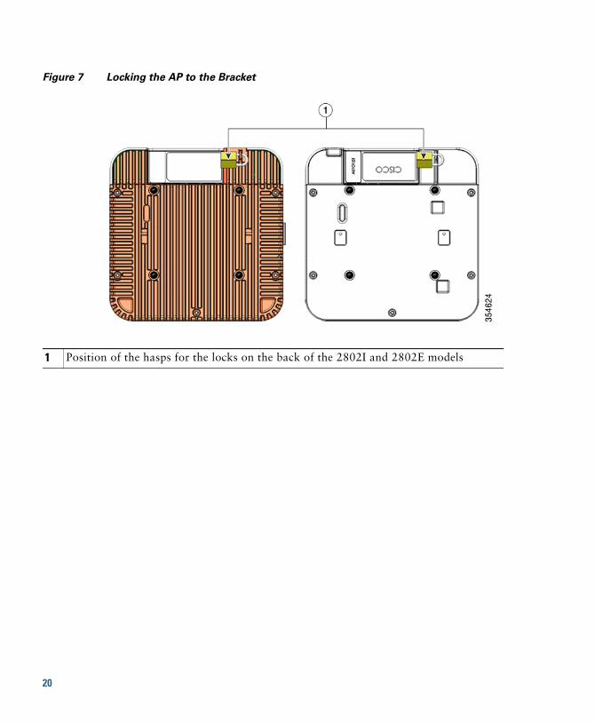
Figure 7 Locking the AP to the Bracket
1 Position of the hasps for the locks on the back of the 2802I and 2802E models
20
10 Powering the Access PointThe AP can be powered through only Power-over-Ethernet (PoE), using:
• 802.3at Cisco Power Injector AIR-PWRINJ6=
• Any 802.3at (25.5 W) compliant switch port
11 Configuring and Deploying the Access PointThis section describes how to connect the access point to a wireless LAN controller. Because the configuration process takes place on the controller, see the Cisco Wireless LAN Controller Configuration Guide for additional information.
The information in this section does not include configuring Link Aggregation. For information on configuring Link Aggregation, see the Cisco Wireless LAN Controller Configuration Guide, Release 8.2, at the following URL:
http://www.cisco.com/c/en/us/td/docs/wireless/controller/8-1/configuration-guide/b_cg81.html
The Controller Discovery ProcessThe access point uses standard Control and Provisioning of Wireless Access Points Protocol (CAPWAP) to communicate between the controller and other wireless access points on the network. CAPWAP is a standard, inter-operable protocol which enables an access controller to manage a collection of wireless termination points. The discovery process using CAPWAP is identical to the Lightweight Access Point Protocol (LWAPP) used with previous Cisco Aironet access points. LWAPP-enabled access points are compatible with CAPWAP, and conversion to a CAPWAP controller is seamless. Deployments can combine CAPWAP and LWAPP software on the controllers.
The functionality provided by the controller does not change except for customers who have Layer 2 deployments, which CAPWAP does not support.
In a CAPWAP environment, a wireless access point discovers a controller by using CAPWAP discovery mechanisms and then sends it a CAPWAP join request. The controller sends the access point a CAPWAP join response allowing the access point to join the controller. When the access point joins the controller, the controller manages its configuration, firmware, control transactions, and data transactions.
21
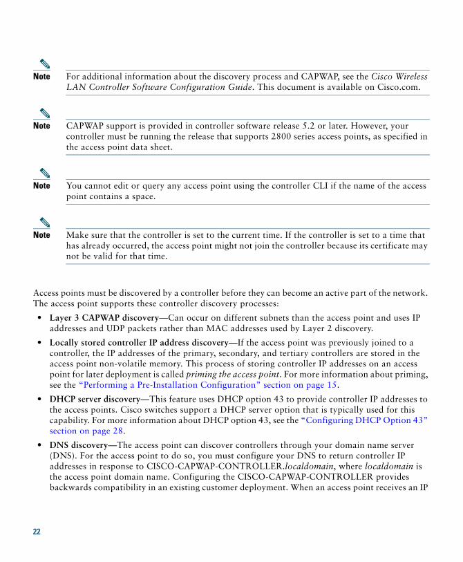
Note For additional information about the discovery process and CAPWAP, see the Cisco Wireless LAN Controller Software Configuration Guide. This document is available on Cisco.com.
Note CAPWAP support is provided in controller software release 5.2 or later. However, your controller must be running the release that supports 2800 series access points, as specified in the access point data sheet.
Note You cannot edit or query any access point using the controller CLI if the name of the access point contains a space.
Note Make sure that the controller is set to the current time. If the controller is set to a time that has already occurred, the access point might not join the controller because its certificate may not be valid for that time.
Access points must be discovered by a controller before they can become an active part of the network. The access point supports these controller discovery processes:
• Layer 3 CAPWAP discovery—Can occur on different subnets than the access point and uses IP addresses and UDP packets rather than MAC addresses used by Layer 2 discovery.
• Locally stored controller IP address discovery—If the access point was previously joined to a controller, the IP addresses of the primary, secondary, and tertiary controllers are stored in the access point non-volatile memory. This process of storing controller IP addresses on an access point for later deployment is called priming the access point. For more information about priming, see the “Performing a Pre-Installation Configuration” section on page 15.
• DHCP server discovery—This feature uses DHCP option 43 to provide controller IP addresses to the access points. Cisco switches support a DHCP server option that is typically used for this capability. For more information about DHCP option 43, see the “Configuring DHCP Option 43” section on page 28.
• DNS discovery—The access point can discover controllers through your domain name server (DNS). For the access point to do so, you must configure your DNS to return controller IP addresses in response to CISCO-CAPWAP-CONTROLLER.localdomain, where localdomain is the access point domain name. Configuring the CISCO-CAPWAP-CONTROLLER provides backwards compatibility in an existing customer deployment. When an access point receives an IP
22
address and DNS information from a DHCP server, it contacts the DNS to resolve CISCO-CAPWAP-CONTROLLER.localdomain. When the DNS sends a list of controller IP addresses, the access point sends discovery requests to the controllers.
Deploying the Access Point on the Wireless NetworkAfter you have mounted the access point, follow these steps to deploy it on the wireless network:
Step 1 Connect and power up the access point.
Step 2 Observe the access point LED (for LED descriptions, see “Checking the Access Point LEDs” section on page 24).
a. When you power up the access point, it begins a power-up sequence that you can verify by observing the access point LED. If the power-up sequence is successful, the discovery and join process begins. During this process, the LED blinks sequentially green, red, and off. When the access point has joined a controller, the LED is chirping green if no clients are associated or green if one or more clients are associated.
b. If the LED is not on, the access point is most likely not receiving power.
c. If the LED blinks sequentially for more than 5 minutes, the access point is unable to find its primary, secondary, and tertiary Cisco wireless LAN controller. Check the connection between the access point and the Cisco wireless LAN controller, and be sure the access point and the Cisco wireless LAN controller are either on the same subnet or that the access point has a route back to its primary, secondary, and tertiary Cisco wireless LAN controller. Also, if the access point is not on the same subnet as the Cisco wireless LAN controller, be sure that there is a properly configured DHCP server on the same subnet as the access point. See the “Configuring DHCP Option 43” section on page 28 for additional information.
Step 3 Reconfigure the Cisco wireless LAN controller so that it is not the Master.
Note A Master Cisco wireless LAN controller should be used only for configuring access points and not in a working network.
23
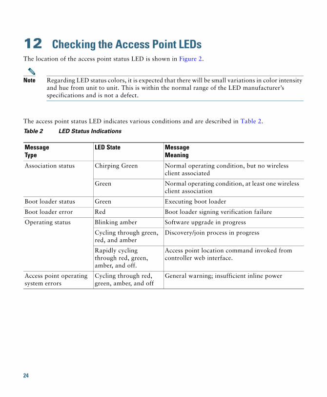
12 Checking the Access Point LEDsThe location of the access point status LED is shown in Figure 2.
Note Regarding LED status colors, it is expected that there will be small variations in color intensity and hue from unit to unit. This is within the normal range of the LED manufacturer’s specifications and is not a defect.
The access point status LED indicates various conditions and are described in Table 2.
Table 2 LED Status Indications
Message Type
LED State MessageMeaning
Association status Chirping Green Normal operating condition, but no wireless client associated
Green Normal operating condition, at least one wireless client association
Boot loader status Green Executing boot loader
Boot loader error Red Boot loader signing verification failure
Operating status Blinking amber Software upgrade in progress
Cycling through green, red, and amber
Discovery/join process in progress
Rapidly cycling through red, green, amber, and off.
Access point location command invoked from controller web interface.
Access point operating system errors
Cycling through red, green, amber, and off
General warning; insufficient inline power
24
13 Miscellaneous Usage and Configuration Guidelines
Using the Mode ButtonUsing the Mode button (see Figure 3) you can:
• Reset the AP to the default factory-shipped configuration.
• Clear the AP internal storage, including all configuration files.
To use the mode button, press, and keep pressed, the mode button on the access point during the AP boot cycle. Wait until the AP status LED changes to Amber. During this, the AP console shows a seconds counter, counting the number of seconds the mode button is pressed. Then:
• To reset the AP to the default factory-shipped configuration, keep the mode button pressed for less than 20 seconds. The AP configuration files are cleared.
This resets all configuration settings to factory defaults, including passwords, WEP keys, the IP address, and the SSID.
• To clear the AP internal storage, including all configuration files and the regulatory domain configuration, keep the mode button pressed for more than 20 seconds, but less than 60 seconds.
The AP status LED changes from Amber to Red, and all the files in the AP storage directory are cleared.
If you keep the mode button pressed for more than 60 seconds, the mode button is assumed faulty and no changes are made.
25
Troubleshooting the Access Point to Cisco Controller Join Process
Note Ensure that your controller is running the latest Cisco Wireless Controller Software Release as specified in the access point data sheet.
Access points can fail to join a controller for many reasons: a RADIUS authorization is pending; self-signed certificates are not enabled on the controller; the access point and the controller regulatory domains don’t match, and so on.
Controller software enables you to configure the access points to send all CAPWAP-related errors to a syslog server. You do not need to enable any debug commands on the controller because all of the CAPWAP error messages can be viewed from the syslog server itself.
The state of the access point is not maintained on the controller until it receives a CAPWAP join request from the access point. Therefore, it can be difficult to determine why the CAPWAP discovery request from a certain access point was rejected. In order to troubleshoot such joining problems without enabling CAPWAP debug commands on the controller, the controller collects information for all access points that send a discovery message to it and maintains information for any access points that have successfully joined it.
The controller collects all join-related information for each access point that sends a CAPWAP discovery request to the controller. Collection begins with the first discovery message received from the access point and ends with the last configuration payload sent from the controller to the access point.
You can view join-related information for up to three times the maximum number of access points supported by the platform for the 2500 series controllers and the Controller Network Module within the Cisco 28/37/28xx Series Integrated Services Routers.
Note The maximum number of access points varies for the Cisco WiSM2, depending on which controller software release is being used.
When the controller is maintaining join-related information for the maximum number of access points, it does not collect information for any more access points.
An access point sends all syslog messages to IP address 255.255.255.255 by default when any of the following conditions are met:
• An access point running software release 8.2.110.0 or later has been newly deployed.
26
• An existing access point running software release 8.2.110.0 or later has been reset after clearing the configuration.
If any of these conditions are met and the access point has not yet joined a controller, you can also configure a DHCP server to return a syslog server IP address to the access point using option 7 on the server. The access point then starts sending all syslog messages to this IP address.
When the access point joins a controller for the first time, the controller sends the global syslog server IP address (the default is 255.255.255.255) to the access point. After that, the access point sends all syslog messages to this IP address until it is overridden by one of the following scenarios:
• The access point is still connected to the same controller, and the global syslog server IP address configuration on the controller has been changed using the config ap syslog host global syslog_server_IP_address command. In this case, the controller sends the new global syslog server IP address to the access point.
• The access point is still connected to the same controller, and a specific syslog server IP address has been configured for the access point on the controller using the config ap syslog host specific Cisco_AP syslog_server_IP_address command. In this case, the controller sends the new specific syslog server IP address to the access point.
• The access point is disconnected from the controller and joins another controller. In this case, the new controller sends its global syslog server IP address to the access point.
• Whenever a new syslog server IP address overrides the existing syslog server IP address, the old address is erased from persistent storage, and the new address is stored in its place. The access point also starts sending all syslog messages to the new IP address provided the access point can reach the syslog server IP address.
You can configure the syslog server for access points and view the access point join information only from the controller CLI.
Important Information for Controller-based DeploymentsKeep these guidelines in mind when you use 2802 series access points:
• The access point can only communicate with Cisco wireless LAN controllers.
• The access point does not support Wireless Domain Services (WDS) and cannot communicate with WDS devices. However, the controller provides functionality equivalent to WDS when the access point joins it.
• CAPWAP does not support Layer 2. The access point must get an IP address and discover the controller using Layer 3, DHCP, DNS, or IP subnet broadcast.
• The access point console port is enabled for monitoring and debug purposes. All configuration commands are disabled when the access point is connected to a controller.
27
Configuring DHCP Option 43You can use DHCP Option 43 to provide a list of controller IP addresses to the access points, enabling them to find and join a controller.
The following is a DHCP Option 43 configuration example on a Windows 2003 Enterprise DHCP server for use with Cisco Aironet lightweight access points. For other DHCP server implementations, consult product documentation for configuring DHCP Option 43. In Option 43, you should use the IP address of the controller management interface.
Note DHCP Option 43 is limited to one access point type per DHCP pool. You must configure a separate DHCP pool for each access point type.
The 2800 series access point uses the type-length-value (TLV) format for DHCP Option 43. DHCP servers must be programmed to return the option based on the access point DHCP Vendor Class Identifier (VCI) string (DHCP Option 43). The VCI string for the 2800 series access point is:
Cisco AP c2800
The format of the TLV block is listed below:
• Type: 0xf1 (decimal 241)
• Length: Number of controller IP addresses * 4
• Value: List of WLC management interfaces
To configure DHCP Option 43 in the embedded Cisco IOS DHCP server, follow these steps:
Step 1 Enter configuration mode at the Cisco IOS CLI.
Step 2 Create the DHCP pool, including the necessary parameters such as default router and name server. A DHCP scope example is as follows:
ip dhcp pool <pool name> network <IP Network> <Netmask> default-router <Default router> dns-server <DNS Server>
Where:<pool name> is the name of the DHCP pool, such as AP2802<IP Network> is the network IP address where the controller resides, such as 10.0.15.1
28
<Netmask> is the subnet mask, such as 255.255.255.0<Default router> is the IP address of the default router, such as 10.0.0.1<DNS Server> is the IP address of the DNS server, such as 10.0.10.2
Step 3 Add the option 43 line using the following syntax:
option 43 hex <hex string>
The hex string is assembled by concatenating the TLV values shown below:
Type + Length + Value
Type is always f1(hex). Length is the number of controller management IP addresses times 4 in hex. Value is the IP address of the controller listed sequentially in hex.
For example, suppose that there are two controllers with management interface IP addresses, 10.126.126.2 and 10.127.127.2. The type is f1(hex). The length is 2 * 4 = 8 = 08 (hex). The IP addresses translate to 0a7e7e02 and 0a7f7f02. Assembling the string then yields f1080a7e7e020a7f7f02. The resulting Cisco IOS command added to the DHCP scope is option 43 hex f1080a7e7e020a7f7f02.
29
14 FAQs
What is Flexible Radio Assignment?The Flexible Radio Assignment (FRA) feature automatically detects when a high number of devices are connected to a network and changes the dual radios in the access point from 2.4 GHz/5 GHz to 5 GHz/5 GHz to serve more clients. The access point performs this function while still monitoring the network for security threats and RF Interference that may affect performance. Flexible Radio Assignment improves mobile user experience for high-density networks.
FRA has the following different modes of operation:
•Default operating mode—Serving clients on both 2.4 GHz and 5 GHz radios.
•Dual 5 GHz Mode—Serving clients on both 5 GHz radios.
•Wireless Security Monitoring—Scanning both 2.4 GHz and 5 GHz radios for security threats while also serving 5 GHz clients.
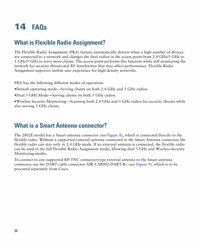
What is a Smart Antenna connector?The 2802E model has a Smart antenna connector (see Figure 8), which is connected directly to the flexible radio. Without a supported external antenna connected to the Smart Antenna connector, the flexible radio can stay only in 2.4 GHz mode. If an external antenna is connected, the flexible radio can be used in the full Flexible Radio Assignment mode, allowing dual 5 GHz and Wireless Security Monitoring modes.
To connect to any supported RP-TNC connector-type external antenna to the Smart antenna connector, use the DART cable connector AIR-CAB002-DART-R= (see Figure 9), which is to be procured separately from Cisco.
30
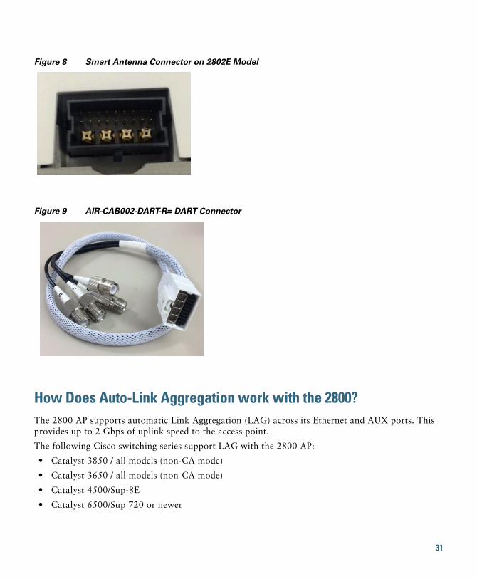
Figure 8 Smart Antenna Connector on 2802E Model
Figure 9 AIR-CAB002-DART-R= DART Connector
How Does Auto-Link Aggregation work with the 2800?The 2800 AP supports automatic Link Aggregation (LAG) across its Ethernet and AUX ports. This provides up to 2 Gbps of uplink speed to the access point.
The following Cisco switching series support LAG with the 2800 AP:
• Catalyst 3850 / all models (non-CA mode)
• Catalyst 3650 / all models (non-CA mode)
• Catalyst 4500/Sup-8E
• Catalyst 6500/Sup 720 or newer
31
What is a ClientLink 4.0? How is it different from Tx-Beamforming?Cisco ClientLink 4.0 is a beamforming capability built into Cisco Aironet wireless LAN access points. When the access point concentrates signals toward the receiving client, that client is better able to hear the AP’s transmission, and so throughput is greater. ClientLink also enhances performance in the uplink (client-to-AP) direction, so that the AP can also better hear the client communications. The result is improved performance in both directions, and doesn’t require any special capabilities in the client device to work.
ClientLink works with all client technologies. It makes sure each client type always operates at the best possible rate, as determined by the 802.11 access technology supported, network conditions, and the distance of the client from the Wi-Fi AP. ClientLink helps maintain maximum client rates.
Can the USB port be used?The USB port does not have any software support at this time.
15 Related DocumentationAll user documentation for the Cisco Aironet 2800 series access point is available at the following URL:
http://www.cisco.com/c/en/us/support/wireless/aironet-2800-series-access-points/tsd-products-support-series-home.html
For detailed information and guidelines for configuring and deploying your access point in a wireless network, see the following documentation:
• Cisco Wireless LAN Controller Configuration Guide, Release 8.2, at the following URL:
http://www.cisco.com/c/en/us/td/docs/wireless/controller/8-2/config-guide/b_cg82.html
• Cisco Aironet 2800 Series Access Point Deployment Guide, at the following URL:
http://www.cisco.com/c/en/us/td/docs/wireless/controller/technotes/8-3/b_cisco_aironet_series_2800_3800_access_point_deployment_guide.html
32
16 Declarations of Conformity and Regulatory InformationThis section provides declarations of conformity and regulatory information for the Cisco Aironet 2800 Series Access Points. You can find additional information at this URL:
www.cisco.com/go/aironet/compliance
Manufacturers Federal Communication Commission Declaration of Conformity Statement
Manufacturer:
Cisco Systems, Inc.170 West Tasman DriveSan Jose, CA 95134-1706USA
This device complies with Part 15 rules. Operation is subject to the following two conditions:
1. This device may not cause harmful interference, and
2. This device must accept any interference received, including interference that may cause undesired operation.
This equipment has been tested and found to comply with the limits of a Class B digital device, pursuant to Part 15 of the FCC Rules. These limits are designed to provide reasonable protection against harmful interference when the equipment is operated in a residential environment. This equipment generates, uses, and radiates radio frequency energy, and if not installed and used in accordance with the instructions, may cause harmful interference. However, there is no guarantee that
Access Point Models Certification Number
AIR-AP2802I-B-K9 LDK102100
AIR-AP2802E-B-K9 LDK102099
Tested To ComplyWith FCC Standards
FOR HOME OR OFFICE USE
33
interference will not occur. If this equipment does cause interference to radio or television reception, which can be determined by turning the equipment off and on, the user is encouraged to correct the interference by one of the following measures:
• Reorient or relocate the receiving antenna.
• Increase separation between the equipment and receiver.
• Connect the equipment to an outlet on a circuit different from which the receiver is connected.
• Consult the dealer or an experienced radio/TV technician.
Caution The Part 15 radio device operates on a non-interference basis with other devices operating at this frequency when using the integrated antennas. Any changes or modification to the product not expressly approved by Cisco could void the user’s authority to operate this device.
VCCI Statement for Japan
Warning
This is a Class B product based on the standard of the Voluntary Control Council for Interference from Information Technology Equipment (VCCI). If this is used near a radio or television receiver in a domestic environment, it may cause radio interference. Install and use the equipment according to the instruction manual.
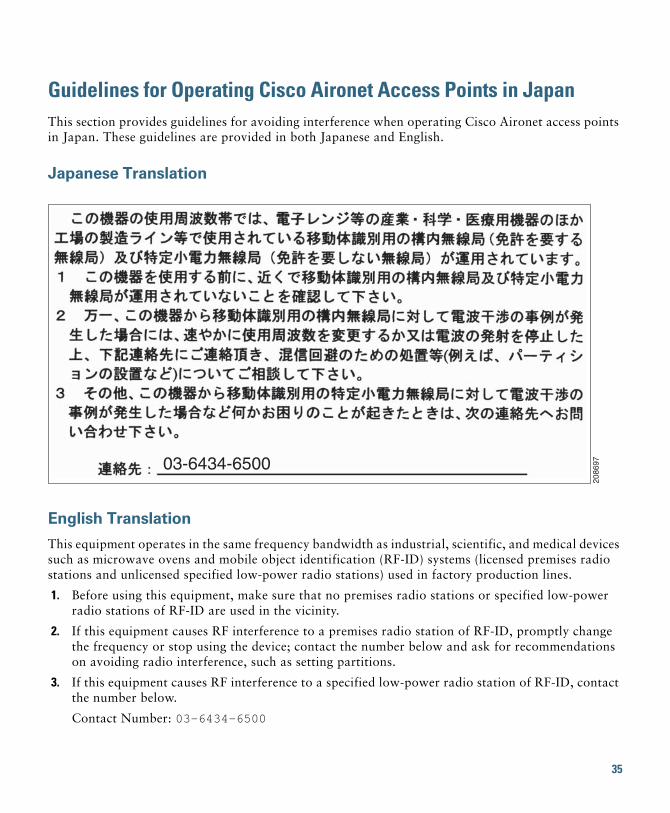
Guidelines for Operating Cisco Aironet Access Points in JapanThis section provides guidelines for avoiding interference when operating Cisco Aironet access points in Japan. These guidelines are provided in both Japanese and English.
Japanese Translation
English Translation
This equipment operates in the same frequency bandwidth as industrial, scientific, and medical devices such as microwave ovens and mobile object identification (RF-ID) systems (licensed premises radio stations and unlicensed specified low-power radio stations) used in factory production lines.
1. Before using this equipment, make sure that no premises radio stations or specified low-power radio stations of RF-ID are used in the vicinity.
2. If this equipment causes RF interference to a premises radio station of RF-ID, promptly change the frequency or stop using the device; contact the number below and ask for recommendations on avoiding radio interference, such as setting partitions.
3. If this equipment causes RF interference to a specified low-power radio station of RF-ID, contact the number below.
Contact Number: 03-6434-6500
03-6434-6500
2086
97
35
Statement 371—Power Cable and AC Adapter
English Translation
When installing the product, please use the provided or designated connection cables/power cables/AC adaptors. Using any other cables/adaptors could cause a malfunction or a fire. Electrical Appliance and Material Safety Law prohibits the use of UL-certified cables (that have the “UL” shown on the code) for any other electrical devices than products designated by CISCO. The use of cables that are certified by Electrical Appliance and Material Safety Law (that have “PSE” shown on the code) is not limited to CISCO-designated products.
36
Industry Canada
Canadian Compliance StatementThis device complies with Industry Canada licence-exempt RSS standard(s). Operation is subject to the following two conditions: (1) this device may not cause interference, and (2) this device must accept any interference, including interference that may cause undesired operation of the device.Le présent appareil est conforme aux CNR d'Industrie Canada applicables aux appareils radio exempts de licence. L'exploitation est autorisée aux deux conditions suivantes : (1) l'appareil ne doit pas produire de brouillage, et (2) l'utilisateur de l'appareil doit accepter tout brouillage radioélectrique subi, même si le brouillage est susceptible d'en compromettre le fonctionnement.
Under Industry Canada regulations, this radio transmitter may only operate using an antenna of a type and maximum (or lesser) gain approved for the transmitter by Industry Canada. To reduce potential radio interference to other users, the antenna type and its gain should be so chosen that the equivalent isotropically radiated power (e.i.r.p.) is not more than that necessary for successful communication.Conformément à la réglementation d'Industrie Canada, le présent émetteur radio peut fonctionner avec une antenne d'un type et d'un gain maximal (ou inférieur) approuvé pour l'émetteur par Industrie Canada. Dans le but de réduire les risques de brouillage radioélectrique à l'intention des autres utilisateurs, il faut choisir le type d'antenne et son gain de sorte que la puissance isotrope rayonnée équivalente (p.i.r.e.) ne dépasse pas l'intensité nécessaire à l'établissement d'une communication satisfaisante.
This radio transmitter has been approved by Industry Canada to operate with the antenna types listed below with the maximum permissible gain and required antenna impedance for each antenna type indicated. Antenna types not included in this list, having a gain greater than the maximum gain indicated for that type, are strictly prohibited for use with this device.Le présent émetteur radio a été approuvé par Industrie Canada pour fonctionner avec les types d'antenne énumérés ci-dessous et ayant un gain admissible maximal et l'impédance requise pour chaque type d'antenne. Les types d'antenne non inclus dans cette liste, ou dont le gain est supérieur au gain maximal indiqué, sont strictement interdits pour l'exploitation de l'émetteur.
Access Point Models Certification Number
AIR-AP2802I-A-K9 2461B-102100
AIR-AP2802E-A-K9 2461B-102099
37
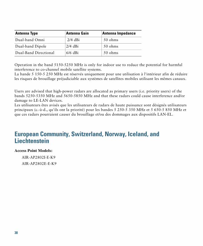
Operation in the band 5150-5250 MHz is only for indoor use to reduce the potential for harmful interference to co-channel mobile satellite systems.La bande 5 150-5 250 MHz est réservés uniquement pour une utilisation à l'intérieur afin de réduire les risques de brouillage préjudiciable aux systèmes de satellites mobiles utilisant les mêmes canaux.
Users are advised that high-power radars are allocated as primary users (i.e. priority users) of the bands 5250-5350 MHz and 5650-5850 MHz and that these radars could cause interference and/or damage to LE-LAN devices.Les utilisateurs êtes avisés que les utilisateurs de radars de haute puissance sont désignés utilisateurs principaux (c.-à-d., qu'ils ont la priorité) pour les bandes 5 250-5 350 MHz et 5 650-5 850 MHz et que ces radars pourraient causer du brouillage et/ou des dommages aux dispositifs LAN-EL.
European Community, Switzerland, Norway, Iceland, and LiechtensteinAccess Point Models:
AIR-AP2802I-E-K9
AIR-AP2802E-E-K9
Antenna Type Antenna Gain Antenna Impedance
Dual-band Omni 2/4 dBi 50 ohms
Dual-band Dipole 2/4 dBi 50 ohms
Dual-Band Directional 6/6 dBi 50 ohms
38
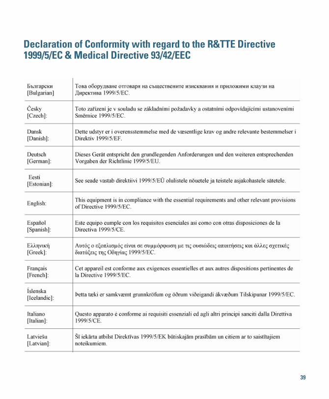
Declaration of Conformity with regard to the R&TTE Directive 1999/5/EC & Medical Directive 93/42/EEC
39
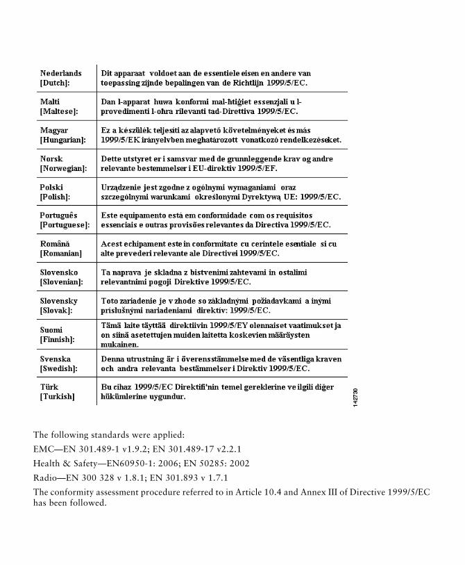
The following standards were applied:
EMC—EN 301.489-1 v1.9.2; EN 301.489-17 v2.2.1
Health & Safety—EN60950-1: 2006; EN 50285: 2002
Radio—EN 300 328 v 1.8.1; EN 301.893 v 1.7.1
The conformity assessment procedure referred to in Article 10.4 and Annex III of Directive 1999/5/EC has been followed.
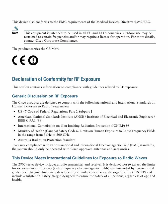
This device also conforms to the EMC requirements of the Medical Devices Directive 93/42/EEC.
Note This equipment is intended to be used in all EU and EFTA countries. Outdoor use may be restricted to certain frequencies and/or may require a license for operation. For more details, contact Cisco Corporate Compliance.
The product carries the CE Mark:
Declaration of Conformity for RF ExposureThis section contains information on compliance with guidelines related to RF exposure.
Generic Discussion on RF Exposure
The Cisco products are designed to comply with the following national and international standards on Human Exposure to Radio Frequencies:
• US 47 Code of Federal Regulations Part 2 Subpart J
• American National Standards Institute (ANSI) / Institute of Electrical and Electronic Engineers / IEEE C 95.1 (99)
• International Commission on Non Ionizing Radiation Protection (ICNIRP) 98
• Ministry of Health (Canada) Safety Code 6. Limits on Human Exposure to Radio Frequency Fields in the range from 3kHz to 300 GHz
• Australia Radiation Protection Standard
To ensure compliance with various national and international Electromagnetic Field (EMF) standards, the system should only be operated with Cisco approved antennas and accessories.
This Device Meets International Guidelines for Exposure to Radio Waves
The 2800 series device includes a radio transmitter and receiver. It is designed not to exceed the limits for exposure to radio waves (radio frequency electromagnetic fields) recommended by international guidelines. The guidelines were developed by an independent scientific organization (ICNIRP) and include a substantial safety margin designed to ensure the safety of all persons, regardless of age and health.
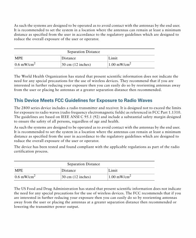
As such the systems are designed to be operated as to avoid contact with the antennas by the end user. It is recommended to set the system in a location where the antennas can remain at least a minimum distance as specified from the user in accordance to the regulatory guidelines which are designed to reduce the overall exposure of the user or operator.
The World Health Organization has stated that present scientific information does not indicate the need for any special precautions for the use of wireless devices. They recommend that if you are interested in further reducing your exposure then you can easily do so by reorienting antennas away from the user or placing he antennas at a greater separation distance then recommended.
This Device Meets FCC Guidelines for Exposure to Radio Waves
The 2800 series device includes a radio transmitter and receiver. It is designed not to exceed the limits for exposure to radio waves (radio frequency electromagnetic fields) as referenced in FCC Part 1.1310. The guidelines are based on IEEE ANSI C 95.1 (92) and include a substantial safety margin designed to ensure the safety of all persons, regardless of age and health.
As such the systems are designed to be operated as to avoid contact with the antennas by the end user. It is recommended to set the system in a location where the antennas can remain at least a minimum distance as specified from the user in accordance to the regulatory guidelines which are designed to reduce the overall exposure of the user or operator.
The device has been tested and found compliant with the applicable regulations as part of the radio certification process.
The US Food and Drug Administration has stated that present scientific information does not indicate the need for any special precautions for the use of wireless devices. The FCC recommends that if you are interested in further reducing your exposure then you can easily do so by reorienting antennas away from the user or placing the antennas at a greater separation distance then recommended or lowering the transmitter power output.
Separation Distance
MPE Distance Limit
0.6 mW/cm2 30 cm (12 inches) 1.00 mW/cm2
Separation Distance
MPE Distance Limit
0.6 mW/cm2 30 cm (12 inches) 1.00 mW/cm2
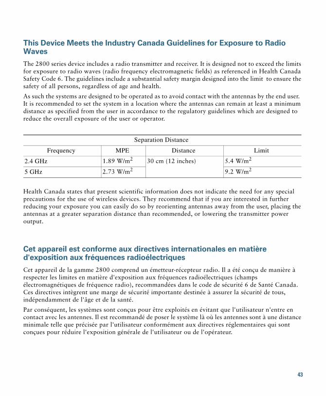
This Device Meets the Industry Canada Guidelines for Exposure to Radio Waves
The 2800 series device includes a radio transmitter and receiver. It is designed not to exceed the limits for exposure to radio waves (radio frequency electromagnetic fields) as referenced in Health Canada Safety Code 6. The guidelines include a substantial safety margin designed into the limit to ensure the safety of all persons, regardless of age and health.
As such the systems are designed to be operated as to avoid contact with the antennas by the end user. It is recommended to set the system in a location where the antennas can remain at least a minimum distance as specified from the user in accordance to the regulatory guidelines which are designed to reduce the overall exposure of the user or operator.
Health Canada states that present scientific information does not indicate the need for any special precautions for the use of wireless devices. They recommend that if you are interested in further reducing your exposure you can easily do so by reorienting antennas away from the user, placing the antennas at a greater separation distance than recommended, or lowering the transmitter power output.
Cet appareil est conforme aux directives internationales en matière d'exposition aux fréquences radioélectriques
Cet appareil de la gamme 2800 comprend un émetteur-récepteur radio. Il a été conçu de manière à respecter les limites en matière d'exposition aux fréquences radioélectriques (champs électromagnétiques de fréquence radio), recommandées dans le code de sécurité 6 de Santé Canada. Ces directives intègrent une marge de sécurité importante destinée à assurer la sécurité de tous, indépendamment de l'âge et de la santé.
Par conséquent, les systèmes sont conçus pour être exploités en évitant que l'utilisateur n'entre en contact avec les antennes. Il est recommandé de poser le système là où les antennes sont à une distance minimale telle que précisée par l'utilisateur conformément aux directives réglementaires qui sont conçues pour réduire l'exposition générale de l'utilisateur ou de l'opérateur.
Separation Distance
Frequency MPE Distance Limit
2.4 GHz 1.89 W/m2 30 cm (12 inches) 5.4 W/m2
5 GHz 2.73 W/m2 9.2 W/m2
43
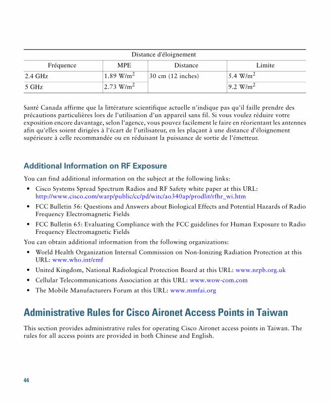
Santé Canada affirme que la littérature scientifique actuelle n'indique pas qu'il faille prendre des précautions particulières lors de l'utilisation d'un appareil sans fil. Si vous voulez réduire votre exposition encore davantage, selon l'agence, vous pouvez facilement le faire en réorientant les antennes afin qu'elles soient dirigées à l'écart de l'utilisateur, en les plaçant à une distance d'éloignement supérieure à celle recommandée ou en réduisant la puissance de sortie de l'émetteur.
Additional Information on RF Exposure
You can find additional information on the subject at the following links:
• Cisco Systems Spread Spectrum Radios and RF Safety white paper at this URL:http://www.cisco.com/warp/public/cc/pd/witc/ao340ap/prodlit/rfhr_wi.htm
• FCC Bulletin 56: Questions and Answers about Biological Effects and Potential Hazards of Radio Frequency Electromagnetic Fields
• FCC Bulletin 65: Evaluating Compliance with the FCC guidelines for Human Exposure to Radio Frequency Electromagnetic Fields
You can obtain additional information from the following organizations:
• World Health Organization Internal Commission on Non-Ionizing Radiation Protection at this URL: www.who.int/emf
• United Kingdom, National Radiological Protection Board at this URL: www.nrpb.org.uk
• Cellular Telecommunications Association at this URL: www.wow-com.com
• The Mobile Manufacturers Forum at this URL: www.mmfai.org
Administrative Rules for Cisco Aironet Access Points in TaiwanThis section provides administrative rules for operating Cisco Aironet access points in Taiwan. The rules for all access points are provided in both Chinese and English.
Distance d'éloignement
Fréquence MPE Distance Limite
2.4 GHz 1.89 W/m2 30 cm (12 inches) 5.4 W/m2
5 GHz 2.73 W/m2 9.2 W/m2
44
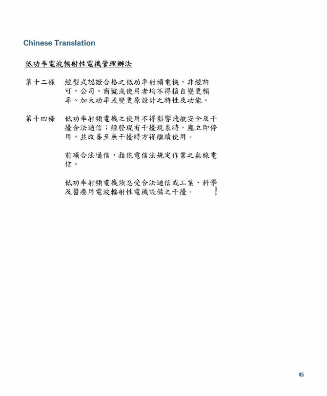
Chinese Translation
45
English Translation
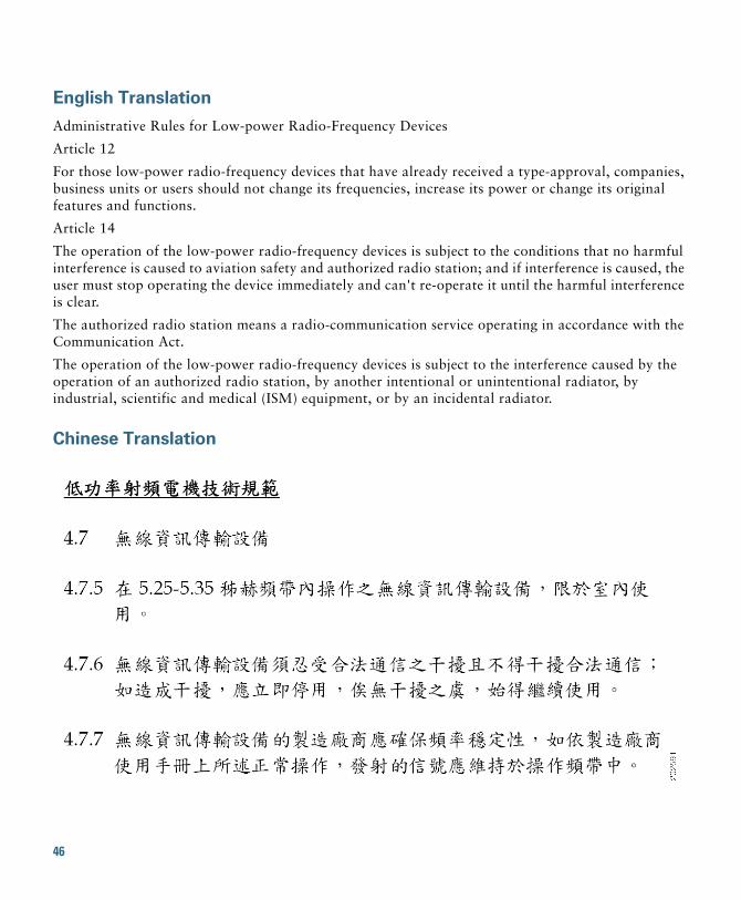
Administrative Rules for Low-power Radio-Frequency Devices
Article 12
For those low-power radio-frequency devices that have already received a type-approval, companies, business units or users should not change its frequencies, increase its power or change its original features and functions.
Article 14
The operation of the low-power radio-frequency devices is subject to the conditions that no harmful interference is caused to aviation safety and authorized radio station; and if interference is caused, the user must stop operating the device immediately and can't re-operate it until the harmful interference is clear.
The authorized radio station means a radio-communication service operating in accordance with the Communication Act.
The operation of the low-power radio-frequency devices is subject to the interference caused by the operation of an authorized radio station, by another intentional or unintentional radiator, by industrial, scientific and medical (ISM) equipment, or by an incidental radiator.
Chinese Translation
46
English Translation
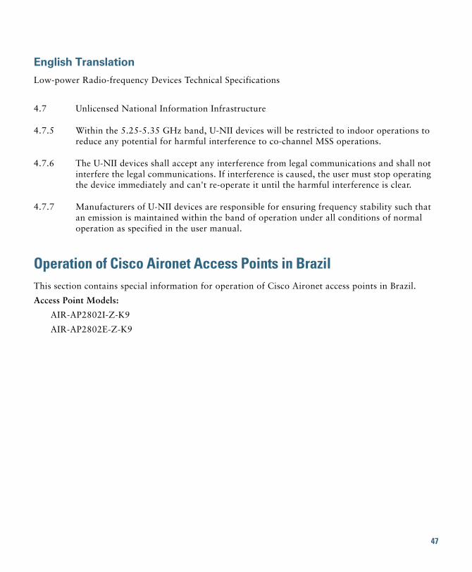
Low-power Radio-frequency Devices Technical Specifications
Operation of Cisco Aironet Access Points in BrazilThis section contains special information for operation of Cisco Aironet access points in Brazil.
Access Point Models:
AIR-AP2802I-Z-K9
AIR-AP2802E-Z-K9
4.7 Unlicensed National Information Infrastructure
4.7.5 Within the 5.25-5.35 GHz band, U-NII devices will be restricted to indoor operations to reduce any potential for harmful interference to co-channel MSS operations.
4.7.6 The U-NII devices shall accept any interference from legal communications and shall not interfere the legal communications. If interference is caused, the user must stop operating the device immediately and can't re-operate it until the harmful interference is clear.
4.7.7 Manufacturers of U-NII devices are responsible for ensuring frequency stability such that an emission is maintained within the band of operation under all conditions of normal operation as specified in the user manual.
47
Figure 10 Brazil Regulatory Information
Portuguese Translation
Este equipamento opera em caráter secundário, isto é, não tem direito a proteção contra interferência prejudicial, mesmo de estações do mesmo tipo, e não pode causar interferência a sistemas operando em caráter primário.
English Translation
This equipment operates on a secondary basis and consequently must accept harmful interference, including interference from stations of the same kind. This equipment may not cause harmful interference to systems operating on a primary basis.
Declaration of Conformity StatementsAll the Declaration of Conformity statements related to this product can be found at the following location: http://www.ciscofax.com
48
17 Obtaining Documentation and Submitting a Service RequestFor information on obtaining documentation, using the Cisco Bug Search Tool (BST), submitting a service request, and gathering additional information, see What’s New in Cisco Product Documentation.
To receive new and revised Cisco technical content directly to your desktop, you can subscribe to the What’s New in Cisco Product Documentation RSS feed. The RSS feeds are a free service.
18 © 2016 Cisco Systems, Inc. All rights reserved.Cisco and the Cisco logo are trademarks or registered trademarks of Cisco and/or its affiliates in the U.S. and other countries. To view a list of Cisco trademarks,go to this URL: www.cisco.com/go/trademarks. Third-party trademarks mentioned are the property of their respective owners. The use of the word partner doesnot imply a partnership relationship between Cisco and any other company. (1110R)
49

50