Hitachi SJ700 and L700 Series Industrial Inverters and Variable Frequency Drives Brochure

No. Contents Page1 Introduction 22 Hitachi PLC 43 Technical Specifications 104 Setting up 115 Configuration 136 Wiring 167 Programming 17
Getting Started
Hitachi PLC

1
Powerful Hitachi PLC
Programming Compatibility
Programming is fully compatible from the smallest PLC (MICRO-EH) to the biggest one (Big-H
series).
2 communication ports
2 communication ports can be used flexibly as programming, HMI communication and general
purpose port for bar code reader or intelligent sensors or scales.
(Note : MICRO-EH does not support the general purpose port.)
Easy programming
Hitachi provides two different programming software.
1) Pro-H : IEC61131-3 standard, Multiprogramming languages.
2) LADDER EDITOR for Windows : Easy ladder programming editor
(The both in one CD package)
High speed micro processor
EH-150 and MICRO-EH has a 32 bits RISC microprocessor called “Super H”.
Compact size
The compact PLC has more capabilities with high reliability, and saves more space and cost.
Open network
EH-150 series has Profibus DP master/slave modules and DeviceNet master/slave modules,
which will increase application range.
Flexible product line up
Digital I/O (normal / high density), analog I/O (V, I, PT100/1000), high speed counter, positioning,
several communication modules are available.
Solution for total automation system
Hitachi provides many options besides PLC as follows.
- Operator panel EH-HMI series
- Remote I/O system EH-RIO series
- Frequency inverters L/SJ100 and L300P/SJ300 series.

2
1. Introduction
What is a PLC?“PLC” stands for Programmable Logic Controller. PLC is an industrial controller, which enables the
control of many devices and signals easily and flexibly. The PLC is “Programmable” by PC or hand
held programming unit. The PLC’s basically work in 3 steps : reading input data, calculating in the
CPU and writing output data according to user program in the PLC.
How it woks?The PLC has a CPU. The CPU executes (scans) a user program. When the CPU reaches the end of
the program, the CPU will return to the program top and execute again, this process is continuous. In
every cycle, input data is read, and output data is written once each.
Input and output data is effective once in a scan.
This is called “Refresh Processing”.
* Scan time (cycle time) depends on your program. (Normally 5 to 30ms.)
Time
1 cycle
Program Scanning
Read Input data Write Output data System processing
and Communication
1 cycle
1 cycle
Input
- Switches
- Sensors
- Encoders, etc.
PLC Output
- Valves
- Relays
- Alarms, etc.
CPU
OutputInput
Calculating
Program

3
Basic flow
Download from PC to CPU
The program is stored in
FLASH memory of CPU
Start the PLC by PC or
RUN switch on the PLC
PLC starts operation according to the user program.
RUN
Program
CPU module
PLC
CPU module
FLASH memoryProgram
Program memory (SRAM)
Data memory (SRAM)
Retentive Data memory(SRAM)
Micro processor
FLASH memory keeps the
program after power OFF.
CPU module
FLASH memory
Program memory (SRAM)
Data memory (SRAM)
Retentive Data memory(SRAM)
Micro processor
Input
Output
ç ç ç
è è è
Programming on PC
Programming softwarerequired (see page 1)
4
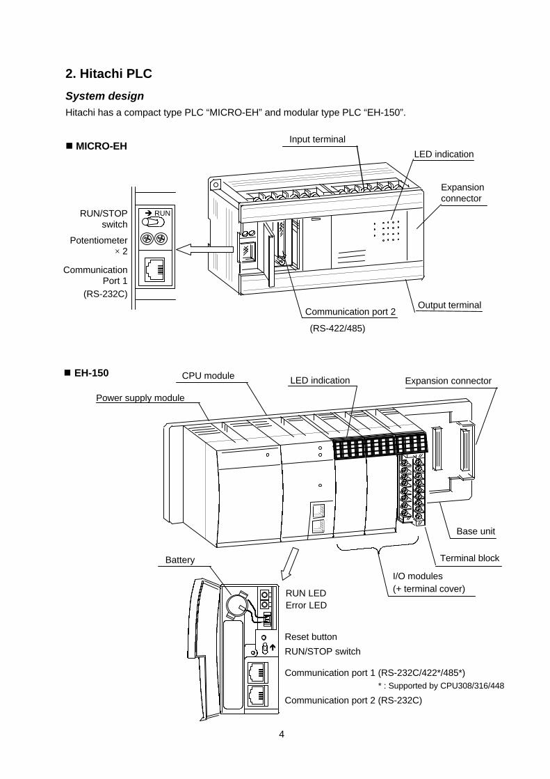
2. Hitachi PLC
System designHitachi has a compact type PLC “MICRO-EH” and modular type PLC “EH-150”.
n MICRO-EH
I/O modules(+ terminal cover)
Base unit
CPU module
Power supply module
Expansion connectorLED indication
Terminal block
n EH-150
Input terminal
Output terminalCommunication port 2
(RS-422/485)
Expansionconnector
LED indication
RUN/STOPswitch
Potentiometer× 2
CommunicationPort 1
è RUN
(RS-232C)
Communication port 1 (RS-232C/422*/485*)
Communication port 2 (RS-232C)
RUN/STOP switch
Reset button
Error LEDRUN LED
Battery
é
* : Supported by CPU308/316/448
5
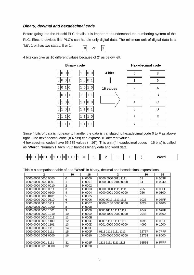
Binary, decimal and hexadecimal code
Before going into the Hitachi PLC details, it is important to understand the numbering system of the
PLC. Electric devices like PLC’s can handle only digital data. The minimum unit of digital data is a
“bit”. 1 bit has two states, 0 or 1.
4 bits can give us 16 different values because of 24 as below left.
Since 4 bits of data is not easy to handle, the data is translated to hexadecimal code 0 to F as aboveright. One hexadecimal code (= 4 bits) can express 16 different values.4 hexadecimal codes have 65,535 values (= 164). This unit (4 hexadecimal codes = 16 bits) is calledas “Word”. Normally Hitachi PLC handles binary data and word data.
This is a comparison table of one “Word” in binary, decimal and hexadecimal expressions.2 10 16 2 10 16
0000 0000 0000 0000 0 H 0000 0000 0000 0011 1111 63 H 003F0000 0000 0000 0001 1 H 0001 0000 0000 0100 0000 64 H 00400000 0000 0000 0010 2 H 00020000 0000 0000 0011 3 H 0003 0000 0000 1111 1111 255 H 00FF0000 0000 0000 0100 4 H 0004 0000 0001 0000 0000 256 H 01000000 0000 0000 0101 5 H 00050000 0000 0000 0110 6 H 0006 0000 0011 1111 1111 1023 H 03FF0000 0000 0000 0111 7 H 0007 0000 0100 0000 0000 1024 H 04000000 0000 0000 1000 8 H 00080000 0000 0000 1001 9 H 0009 0000 0111 1111 1111 2047 H 07FF0000 0000 0000 1010 10 H 000A 0000 1000 0000 0000 2048 H 08000000 0000 0000 1011 11 H 000B0000 0000 0000 1100 12 H 000C 0000 1111 1111 1111 4095 H 0FFF0000 0000 0000 1101 13 H 000D 0001 0000 0000 0000 4096 H 10000000 0000 0000 1110 14 H 000E0000 0000 0000 1111 15 H 000F 0111 1111 1111 1111 32767 H 7FFF0000 0000 0001 0000 16 H 0010 1000 0000 0000 0000 32768 H 8000
0000 0000 0001 1111 31 H 001F 1111 1111 1111 1111 65535 H FFFF0000 0000 0010 0000 32 H 0020
0 0 0 0
0 0 0 1
0 0 1 0
0 0 1 1
0 1 0 0
0 1 0 1
0 1 1 0
0 1 1 1
1 0 0 0
1 0 0 1
1 0 1 0
1 0 1 1
1 1 0 0
1 1 0 1
1 1 1 0
1 1 1 1
0
1
2
3
4
5
6
7
8
9
A
B
C
D
E
F
Binary code Hexadecimal code
4 bits
16 values
0 0 0 1 10 0 1 0 1 1 1 0 1 1 1 1 2 E F Word
0 1or

6
I/O data types
Hitachi PLC’s handles the following I/O.
Bit(for Digital data, etc)
Word(for Analog data, etc)
Double Word
Input X ¨¨¨¨ [D] WX ¨¨¨ [H] DX ¨¨¨ [H]External
I/Os Output Y ¨¨¨¨ [D] WY ¨¨¨ [H] DY ¨¨¨ [H]
Normal memory R ¨¨¨¨ [H] WR ¨¨¨ [H] DR ¨¨¨ [H]
Shared memory M ¨¨¨¨ [H] WM ¨¨¨ [H] DM ¨¨¨ [H]
Link memory L ¨¨¨¨ [H] WL ¨¨¨ [H] DL ¨¨¨ [H]
Timer (TD,SS, etc.) TD ¨¨¨ [D] - -
Counter (CU, etc.) CU ¨¨¨ [D] - -
Edge detection á DIF ¨¨¨ [D] - -
Internal
I/Os
Edge detection â DFN ¨¨¨ [D] - -
Note : [D] ... Decimal (ex. 00,01,...,09,10,...,15,16,17,18,19,20,21,...)
[H] ... Hexadecimal (ex. 00,01,...,09,0A,0B,...0F,10,11,...1F,20,21,...)
n Bit, Word and Double Word
Double Word consists of 2 Words, and 1 Word consists of 16 bits as below.
n External I/O
External I/Os (X, Y, WX, WY, etc.) are direct addresses for each digital input/output module or analog
input/output module. Please note bit I/Os X and Y are decimal expression.
(WX/WY can be used as access command or data for high function modules like the counter
module.)
X0
WX 0
X1
X2
X13
X14
X15
X16
WX 1
X17
X18
X29
X30
X31
X32
WX 2
X33
X34
X45
X46
X47
DX 0
DX 1
DX 2
Bit
15
Bit
14
Bit
13
Bit
12
Bit
11
Bit
10
Bit9
Bit8
Bit7
Bit6
Bit5
Bit4
Bit3
Bit2
Bit1
Bit0
Word (16 bits)
Bit
15
Bit
14
Bit
13
Bit
12
Bit
11
Bit
10
Bit9
Bit8
Bit7
Bit6
Bit5
Bit4
Bit3
Bit2
Bit1
Bit0
Double Word (32 bits)
Example : WR 0 = H’1234, WR 1 = H’5678 è DR 0 = H’5678 1234WR 1 WR 0

7
n Internal I/O
Internal I/O (R, WR, M, WM, etc.) means data memory. This data memory area can be read or
written freely for flags, parameters, set point values or calculation depending on your program.
* Refer to the chapter “Programming” for further information about TD, CU, DIF and DFN.
Note : “R” and “WR/DR” are physically separated memory areas.
[ M, L ]
Note : “M”, “WM” and “DM” are in one common memory area. (L/WL/DL as well.)
WR 0 WR 1 WR 2
DR 0
DR 1
DR 2
No bit access No bit access No bit access
R0
R1
R2
R3
R4
R5
R6
R7
R8
R9
RA
RB
RC
RD
RE
RF
R10
R11
R12
R13
R14
R15
R16
R17
R18
R19
R1A
R1B
R1C
R1D
R1E
R1F
R20
R21
M0
WM 0
M1
M2
MD
ME
MF
M10
WM 1
M11
M12
M1D
M1E
M1F
M20
WM 2
M21
M22
M2D
M2E
M2F
DM 0
DM 1
DM 2
Note : “L” is available only for the LINK module
[ R, WR ]

8
I/O address of MICRO-EH
The I/O address of MICRO-EH is fixed.
X0 – X5Input
Y100 – Y103Output
X0 – X7
Y100 – Y105
X0 – X15
Y100 – Y111
n 10/14/28 points
DI × 6
DO × 4
DI × 8
DO × 6
DI × 16
DO × 12
X0 – X12
Y100 – Y109
WX30,31
WY40
n 23 points
DO × 10
DI × 13 AI × 2
AO × 1
n Expansion units
DIDOAIAO
: Digital Input: Digital Output: Analog Input: Analog Output
Y1016 – Y1021
X2000 – X2007
Y2016 – Y2021
X3000 – X3007
Y3016 – Y3021
X4000 – X4007
Y4016 – Y4021
X1000 – X1007DI × 8
DO × 6

9
I/O address of EH-150The I/O address of EH-150 depends on the module location and I/O type.
& Hexadecimal expression
As mentioned above, each hexadecimal code can be expressed as 4 bits.
0 : 0000 4 : 0100 8 : 1000 C : 11001 : 0001 5 : 0101 9 : 1001 D : 11012 : 0010 6 : 0110 A : 1010 E : 11103 : 0011 7 : 0111 B : 1011 F : 1111
Since one word (WX, WY, WM, etc.) consists of 16 bits (X, Y, M, etc.), the relation between WX/WY
and X/Y is as follows. (“H” stands for hexadecimal.)
WX 0 = H1234 = 0001 0010 0011 0100
WY 5 = H00FF = 0000 0000 1111 1111
X15 X0X7X8
Y15 Y0Y7Y8
Bit number (decimal)
Slot number (0 - 7)
Unit number (0 - 1)
I/O type
Word number
Slot number (0 - 7)
Unit number (0 - 1)
I/O type
[ Bit ] X ¨ ¨ ¨¨ [ Word ] WX ¨ ¨ ¨
X0000 – X0015
CPUPower supply
Basic unit
(Unit 0)
Expansion unit
(Unit 1)
I/O controller module
EH
-XD
16
EH
-YT
P64
EH
-YT
P32
EH
-AX
8V
EH
-XD
16
EH
-AX
8V
X0100 – X0115
WX020 – WX027E
H-A
Y4V
Y0300 – Y0363
WY040 – WY043
Y1200 – Y1231
EH
-XD
64
X1000 – X1063
WX140 – WX147
16 DI 16 DI
8 AI
64 DO
4 AO
64 DI
32 DO
4 AI
0 1 2 3 4
0 1 2 3 4
* 16 DI : 16 points Digital Input module, 4 AO : 4 channels Analog Output module

10
3. Technical specifications
EH-150MICRO-EH10/14/23,28 CPU104 CPU208 CPU308 CPU316 CPU448
General specificationSpeed ofBinarycommand
0.9µs 1.0µs 0.1µs
Memory size 3 kstep 4 kstep 8 kstep 8 kstep 16 kstep 48 kstepI/O points 10/70/84 512 1,024Exp. unit Up to 4 - 1Commands 98 152PID - üClock ü *1 - üPort 1 RS-232C RS-232C/422/485Port 2 RS-422/485 *1 RS-232CMemoryboard (planned) - ü (optional)
Modem ü - üInternal memory
R 1984 bits (R0 – R7BF)
WR 4,096 word(WR0 – FFF)
8,192 w.(WR0 – 1FFF)
17,408 w.(WR0 – 43FF)
22,528 w.(WR0 – 57FF)
50,176 w.(WR0 – C3FF)
M, WM 16,384 points = 1,024 w. (M0 – 3FFF = WM0 – 3FF)
L, WL - 16,384 points ×2 = 1,024 w. ×2 (L0 – 3FFF = WM0 – 3FF, L10000 – 13FFF = WL1000 – 13FF
Special R 64 points (R7C0 – 7FFSpecial WR 512 words (WRF000 – F1FF)Timer (TD)/counter (CU)points
256 points(TD + CU)
0.01s : 64 pts.
512 points (TD + CU) *2(TD : up to 256 points, 0.01s base TD : up to 64 points.)
TD /CUsetting value
TD : 65,535 with 0.01, 0.1 or 1 sec. time baseCU : 65,535 times
Edge detect 512 points (DIF0 - 511) / 512 points (DFN0 - 511)*1 : Only 23, 28 points module.*2 : (TD) is up to 256 (TD0 - 255), and counter (CU) is up to 511 (CU0 - 511) for EH-150 series. TD number
is not allowed to use same as CU number, and vice versa.
Special internal registers R, WRThe special internal registers are some flags, diagnostic information and parameter setting area to operate
the PLC easily and flexibly. The following list is a part of this area and error code in WRF000.
Address Description Set by Reset by Error code in WRF000
R7E3 ON while the first scan CPU CPU H13 micro processor errorR7E4 Always ON CPU CPU H33 memory size errorR7E5 0.02s clock (0.01s ON, 0.01s OFF) CPU CPU H34 program (syntax) errorR7E6 0.1s clock (0.05s ON, 0.05s OFF) CPU CPU H41 I/O configuration errorR7E7 1s clock (0.5s ON, 0.5s OFF) CPU CPUR7EC Clear error code user CPU
H44 scan time error(normal scan)
WRF000 Error code (See right table.) CPU userWRF00B – 00F Calendar CPU -
H45 scan time error(periodic scan)
WRF010 – 012 Scan time (max. / current / min.) CPU CPU H71 Battery lowWRF01B – 01F Calendar to read/write user userWRF050 ROM version CPU CPUWRF051 FLASH ROM version CPU CPU
(see below)(see below)

11
4. Setting up
Baud rate for PLC
n MICRO-EHConfigure baud rate for communication port 1 and 2. For normal use, set the dip switch 1 ON. The
port 1 will then be available for programming with 19.2kbps.
Dip switchPort No. Communication type /baud rate 1 2 3 4
WRF01A WRF03D
38.4 kbps ON - ON - - -19.2 kbps ON - - - - -9600 bps - - ON - - -
Standard
4800 bps - - - - - -4800 bps - ON - - H0000 -9600 bps - ON - - H0100 -19.2 kbps - ON - - H0200 -38.4 kbps - ON - - H0300 -57.6 kbps - ON - - H0400 -
Port 1RS-232CDedicated port(Programming / HMI) Modem
mode
2400 bps - ON - - H0500 -4800 bps - - - - - H80009600 bps - - - - - H810019.2 kbps - - - - - H8200
Standard
38.4 kbps - - - - - H83004800 bps - - - - - HA0xx9600 bps - - - - - HA1xx19.2 kbps - - - - - HA2xx
Port 2RS422/485Dedicated port(Programming / HMI) Multidrop
38.4 kbps - - - - - HA3xx
ON
1 2 3 4
Behind the cover

12
n EH-150
Configure baud rate for communication port 1 and 2. For normal use, set the dip switch 1, 3, 5 all
ON, and the toggle switch ON. Both ports will then be available for programming with 19.2kbps.
Dip switch and toggle switch configurationRemote SW 1 : ONRUN/STOP
Mode RUN switch SW 1 : OFF4,800 bps SW 3, 4 : ON, ON9,600 bps SW 3, 4 : OFF, ON19,200 bps SW 3, 4 : ON, OFF
Dedicated port(Programming / HMI)
SW 5 : ON
38,400 bps SW 3, 4 : OFF, OFFModem mode SW 2 : ON
Port 1
General purpose port SW 5 : OFFNormal mode SW 2 : OFF4,800 bps SW 6, T : OFF, OFF9,600 bps SW 6, T : ON, OFF19,200 bps SW 6, T : OFF, ON
Port 2 Dedicated port(Programming / HMI)
38,400 bps SW 6, T : ON, ON
SW1-6 = Dip switch, SW T = Toggle switch
Baud rate for PC (Programming software)The baud rate setting procedure depends on the programming software.
Pro-H Right mouse click on “Resource” - [Setting] – [Communication]Ladder Editor for Win. [Utility] – [Environment] – [Communication]
Dip switch 1, 3, 5 : ON
Toggle switch : ON
19.2 kbps for both ports
Toggle switch
CPU module
Dip switch
8
ON
OFF
ONOFF
76
5
4
3
2
1

13
5. Configuration
The user program is up/downloaded from/to the PLC as described above.
Besides the user program, several other pieces of important information are up/downloaded from/to
the PLC together with user program. Ensure the following settings are configured correctly.
The “I/O configuration” and “Memory size” in the PC program must be same as the actual I/O
configuration and memory size in the PLC.
I/O configurationn MICRO-EH
The I/O configuration of MICRO-EH is fixed for each model. This table can be read out from the PLC
when on-line.
10, 14, 28 points basic module
Unit 0 Unit 1Slot 0 X48Slot 1 Y32Slot 2Slot 3Slot 4
23 points basic module
Unit 0 Unit 1Slot 0 X48Slot 1 Y32Slot 2 Empty 16Slot 3 WX 4Slot 4 WY 4
Expansion module
Unit 0 Unit 1Slot 0 X48 B1/1Slot 1 Y32Slot 2Slot 3Slot 4
PC
Ø I/O configuration Ø Memory size Ø Operation parameters Ø Retentive area, etc.
User program
PLC
I/O configurationMemory size
28 points14 points
14 points exp.
10 points
23 points
28 points
I/O configuration of 10,14 and 28points module is fixed (X48, Y32).
14
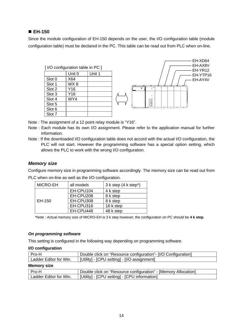
n EH-150Since the module configuration of EH-150 depends on the user, the I/O configuration table (module
configuration table) must be declared in the PC. This table can be read out from PLC when on-line.
[ I/O configuration table in PC ]
Unit 0 Unit 1Slot 0 X64Slot 1 WX 8Slot 2 Y16Slot 3 Y16Slot 4 WY4Slot 5Slot 6Slot 7
Note : The assignment of a 12 point relay module is “Y16”.Note : Each module has its own I/O assignment. Please refer to the application manual for further
information.Note : If the downloaded I/O configuration table does not accord with the actual I/O configuration, the
PLC will not start. However the programming software has a special option setting, whichallows the PLC to work with the wrong I/O configuration.
Memory sizeConfigure memory size in programming software accordingly. The memory size can be read out from
PLC when on-line as well as the I/O configuration.
MICRO-EH all models 3 k step (4 k step*)EH-CPU104 4 k stepEH-CPU208 8 k stepEH-CPU308 8 k stepEH-CPU316 16 k step
EH-150
EH-CPU448 48 k step
*Note : Actual memory size of MICRO-EH is 3 k step however, the configuration on PC should be 4 k step.
On programming software
This setting is configured in the following way depending on programming software.
I/O configurationPro-H Double click on “Resource configuration”- [I/O Configuration]Ladder Editor for Win. [Utility] - [CPU setting] - [I/O assignment]
Memory sizePro-H Double click on “Resource configuration” - [Memory Allocation]Ladder Editor for Win. [Utility] - [CPU setting] - [CPU information]
EH-XD64EH-AX8VEH-YR12EH-YTP16EH-AY4V
15
Operation parametersSeveral optional parameters are available. Configure if necessary.
Operation parameters Default EnableRUN input Disable Set the addressMax. scan time 100 ms Set the timeOperation mode in wrong I/O configuration STOP RUNOperation mode in expansion unit error STOP RUNOperation mode in remote unit error STOP RUNLINK area range Disable Set the rangeetc.
If the “Operation mode in wrong I/O configuration” is enabled, CPU can work without actual I/Omodules, which is useful for debugging or testing.
On programming softwarePro-H Double click on “Resource configuration”- [Operation parameters]Ladder Editor for Win. [Utility] - [CPU setting] - [Operation parameters]
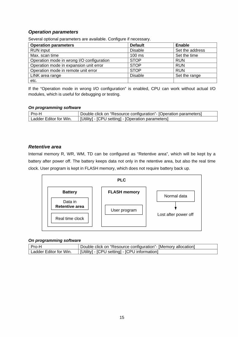
Retentive areaInternal memory R, WR, WM, TD can be configured as “Retentive area”, which will be kept by a
battery after power off. The battery keeps data not only in the retentive area, but also the real time
clock. User program is kept in FLASH memory, which does not require battery back up.
On programming softwarePro-H Double click on “Resource configuration”- [Memory allocation]Ladder Editor for Win. [Utility] - [CPU setting] - [CPU information]
PLC
FLASH memory
User program
Battery
Data inRetentive area
Real time clockLost after power off
Normal data
16
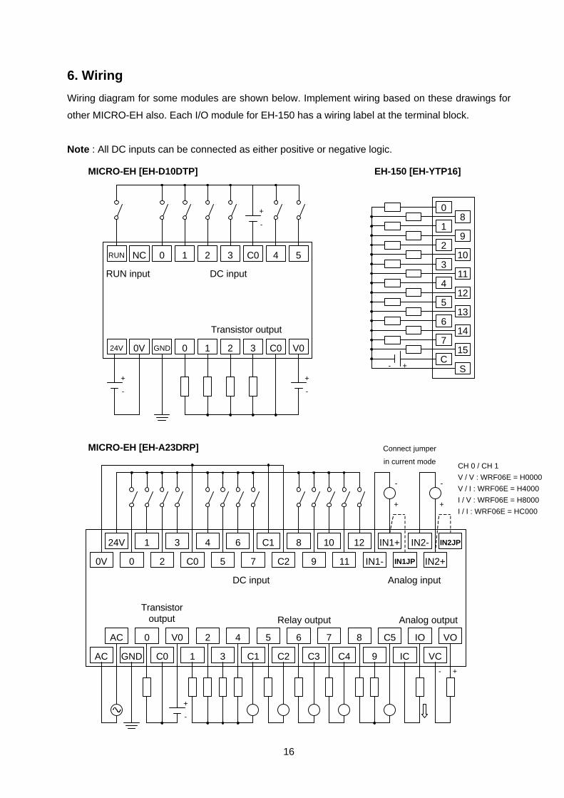
6. Wiring
Wiring diagram for some modules are shown below. Implement wiring based on these drawings for
other MICRO-EH also. Each I/O module for EH-150 has a wiring label at the terminal block.
Note : All DC inputs can be connected as either positive or negative logic.
24V 1
00V
3 4
C02
6 C1
75
8 10
9C2
12 IN1+
IN1-11
IN2- IN2JP
IN2+IN1JP
AC 0
GNDAC
V0 2
1C0
4 5
C13
6 7
C3C2
8 C5
9C4
IO VO
VCIC
-
+
-
+
Connect jumper
in current mode
-
+
+-
DC input Analog input
Transistoroutput Relay output Analog output
0
18
92
310
114
512
136
714
15C
S+-
MICRO-EH [EH-D10DTP] EH-150 [EH-YTP16]
MICRO-EH [EH-A23DRP]
RUN NC 0 1 2 3 C0 4 5
-
+
DC input
Transistor output
-
+
24V 0V GND 0 1 2 3 C0 V0
-
+
RUN input
CH 0 / CH 1
V / V : WRF06E = H0000
V / I : WRF06E = H4000
I / V : WRF06E = H8000
I / I : WRF06E = HC000
17
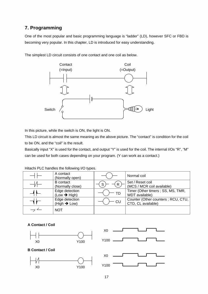
7. Programming
One of the most popular and basic programming language is “ladder” (LD), however SFC or FBD is
becoming very popular. In this chapter, LD is introduced for easy understanding.
The simplest LD circuit consists of one contact and one coil as below.
In this picture, while the switch is ON, the light is ON.
This LD circuit is almost the same meaning as the above picture. The “contact” is condition for the coil
to be ON, and the “coil” is the result.
Basically input “X” is used for the contact, and output “Y” is used for the coil. The internal I/Os “R”, “M”
can be used for both cases depending on your program. (Y can work as a contact.)
Hitachi PLC handles the following I/O types.
A contact(Normally open) Normal coil
B contact(Normally close)
Set / Reset coil(MCS / MCR coil available)
Edge detection(Low è High)
Timer (Other timers ; SS, MS, TMR,WDT available)
Edge detection(High è Low)
Counter (Other counters ; RCU, CTU,CTD, CL available)
NOT
X0 Y100
X0
Y100
A Contact / Coil
X0
Y100
B Contact / Coil
X0 Y100
Contact Coil(=Input) (=Output)
Switch Light
S R
TD
CU

18
& De Morgan’s Laws
NOT ( A AND B ) = ( NOT A ) OR ( NOT B ) A × B = A + B
NOT ( A OR B ) = ( NOT A ) AND ( NOT B ) A + B = A × B
X0
Y100
Edge detection (á) : DIF
X0 Y100DIF 0
1 scan time
X0
Y100
Edge detection (â) : DFN
X0 Y100DFN 0
1 scan time
X0
X1
Set/Reset coil
X0 Y100
S
X1 Y100
RY100
X0 Y100
X0
Y100
AND
X1X1
X0 Y100
X0
Y100
OR
X1
X1
Internal memory R, M can be used instead of X and Y.
X0 Y100
X0
Y100
NOT

19
Note : MICRO-EH supports above 2 timers only.Note : EH-150 supports Mono-stable timer “MS”, integral timer “TMR” and Watch dog timer “WDT”
besides above ones.
ON delay timer : TD
X0 TD 0
TD 0 Y100
120.1s
X012
TD 00.1s Y100
n Pro-H (LD)
n LADDER EDITOR
TD 00.1s
Y100
12
X0
n Pro-H (FBD)
X0
TD 0Y100
1.2s
TC 0
12
* TC is a word data counting 0 up to 65,535.
Single Shot timer : SS
X0 SS 0
TD 0 Y100
120.1s
n LADDER EDITOR
X012
SS 00.1s Y100
n Pro-H (LD)
SS 00.1s
Y100
12
X0
n Pro-H (FBD)
X0
TD 0Y100
1.2s
TC 0
12
* TC is a word data counting 0 up to 65,535.

20
R5
Inline box
WR0 = WR1 OR H00FF
WR2 = WR2 + 10
SHL (WM100,1)
TRNS 0 (WX0, WR0, R0)
FUN 80 (WR3)
DIF2
Up to 19 lines
Many commands are available Basic commands : 35 ∼ Arithmetical commands : 22 ∼ Application commands : 25 ∼ Control commands : 12 ∼ Special function commands : 16 ∼
Comparison box
H3000<
WX 3 Y100
n LADDER EDITOR
WX 3
16#3000
GT 00.1s Y100
n Pro-H (LD)
GT 00.1s
Y100
16#3000
WX 3
n Pro-H (FBD)
WX 3
Y100
While WX 3 exceeds H3000, Y100 is ON.
H3000
* GT : Greater Than