GET CONNECTEDGet Smart • Get Efficient • Get to Market … · GET CONNECTEDGet Smart • Get...
23
with Future Connectivity Solutions GET CONNECTED Get Smart • Get Efficient • Get to Market Quickly FEATURED TECHNOLOGIES 802.15.4 Antennas Bluetooth Cellular GPS/GNSS Wi-Fi FEATURED TECHNICAL VIEW Smart About Bluetooth® Smart by Allen Cabreros NEW PRODUCT INTRODUCTIONS GPS and GNSS Modules by Linx Technologies QuickCarrier™ Cellular USB Dongle by Multi-Tech Systems RN4020 Bluetooth® Low Energy Moduleby by Microchip Low Energy Bluetooth SMART Module Type ZY by Murata Connectivity Solutions ISSUE 01 Taking the world wireless
Transcript of GET CONNECTEDGet Smart • Get Efficient • Get to Market … · GET CONNECTEDGet Smart • Get...

with Future Connectivity SolutionsGET CONNECTEDGet Smart • Get Efficient • Get to Market Quickly
FEATURED TECHNOLOGIES802.15.4
AntennasBluetooth
CellularGPS/GNSS
Wi-Fi
FEATURED TECHNICAL VIEW Smart About Bluetooth® Smart
by Allen Cabreros
NEW PRODUCT INTRODUCTIONS GPS and GNSS Modules
by Linx Technologies
QuickCarrier™ Cellular USB Dongle by Multi-Tech Systems
RN4020 Bluetooth® Low Energy Moduleby
by Microchip
Low Energy Bluetooth SMART Module Type ZY by Murata
Connectivity Solutions
ISSU
E01
Taking the world wireless
TABLE OF CONTENTS
802.15.4DIGI XBee Wi-Fi embedded RF modules
NXP JN5168-001-Myy JenNet-IP, ZigBee PRO and IEEE802.15.4 Module
AntennasYageo GPS/Glonass ceramic patch antennas
Yageo WLAN/BT/ZigBee Ceramic Chip Antenna
Yageo WLAN/BT/ZigBee 2.4GHz PCB Antenna
BluetoothFuture Connectivity Solutions Smart About Bluetooth® Smart
Microchip RN4020 Bluetooth® Low Energy Module
Murata Murata Low Energy Bluetooth SMART Module : Type ZY
Panasonic PAN1026 Series Place and Play Bluetooth® Module
STMicroelectronics SPBT2632 series
CellularMulti-Tech QuickCarrier™ USB-D Cellular Dongle Sierra Wireless AirPrime SL Series
GPS / GNSS ModulesLinx Technologies GPS and GNSS Modules
Wi-FiGainSpan GS1011M Low Power Wi-Fi Module Family
Silex 802.11a/b/g/n Plus Bluetooth SDIO Module
4
5
6
6
7
8
12
13
14
15
16
20
21
18
2
19

ISSU
E 01
3
Contact UsWorldwide Corporate Headquarters
237 Hymus Boulevard
Pointe Claire, Quebec,Canada
H9R 5C7
Tel.: (514) 694-7710
Fax: (514) 695-3707
Request design helpwww.FutureElectronics.com/ConnectivitySolutionsConnectivity Solutions
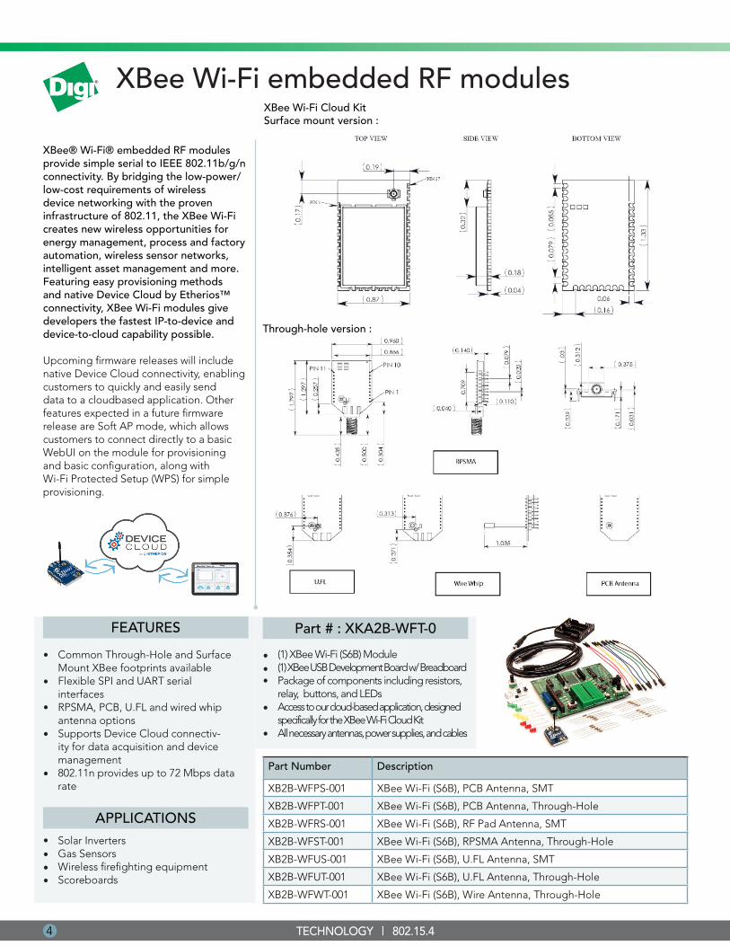
XBee Wi-Fi embedded RF modules
XBee® Wi-Fi® embedded RF modules provide simple serial to IEEE 802.11b/g/n connectivity. By bridging the low-power/low-cost requirements of wireless device networking with the proven infrastructure of 802.11, the XBee Wi-Fi creates new wireless opportunities for energy management, process and factory automation, wireless sensor networks, intelligent asset management and more. Featuring easy provisioning methods and native Device Cloud by Etherios™ connectivity, XBee Wi-Fi modules give developers the fastest IP-to-device and device-to-cloud capability possible.
Upcoming firmware releases will include native Device Cloud connectivity, enabling customers to quickly and easily send data to a cloudbased application. Other features expected in a future firmware release are Soft AP mode, which allows customers to connect directly to a basic WebUI on the module for provisioning and basic configuration, along with Wi-Fi Protected Setup (WPS) for simple provisioning.
XBee Wi-Fi Cloud Kit Surface mount version :
(1) XBee Wi-Fi (S6B) Module(1) XBee USB Development Board w/ BreadboardPackage of components including resistors, relay, buttons, and LEDsAccess to our cloud-based application, designed specifically for the XBee Wi-Fi Cloud KitAll necessary antennas, power supplies, and cables
Part # : XKA2B-WFT-0
•••
4
FEATURES
Common Through-Hole and Surface Mount XBee footprints availableFlexible SPI and UART serial interfaces RPSMA, PCB, U.FL and wired whip antenna options Supports Device Cloud connectiv-ity for data acquisition and device management802.11n provides up to 72 Mbps data rate
•
•
•
•
APPLICATIONS
•
Solar InvertersGas SensorsWireless firefighting equipmentScoreboards
••••
TECHNOLOGY | 802.15.4
Part Number Description
XB2B-WFPS-001 XBee Wi-Fi (S6B), PCB Antenna, SMT
XB2B-WFPT-001 XBee Wi-Fi (S6B), PCB Antenna, Through-Hole
XB2B-WFRS-001 XBee Wi-Fi (S6B), RF Pad Antenna, SMT
XB2B-WFST-001 XBee Wi-Fi (S6B), RPSMA Antenna, Through-Hole
XB2B-WFUS-001 XBee Wi-Fi (S6B), U.FL Antenna, SMT
XB2B-WFUT-001 XBee Wi-Fi (S6B), U.FL Antenna, Through-Hole
XB2B-WFWT-001 XBee Wi-Fi (S6B), Wire Antenna, Through-Hole
•
•
Through-hole version :
ISSU
E 01
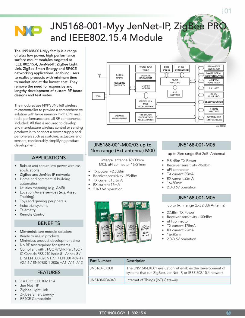
JN5168-001-Myy JenNet-IP, ZigBee PRO and IEEE802.15.4 Module
The JN5168-001-Myy family is a range of ultra low power, high performance surface mount modules targeted at IEEE 802.15.4, JenNet-IP, ZigBee Light Link, ZigBee Smart Energy and RF4CE networking applications, enabling users to realise products with minimum time to market and at the lowest cost. They remove the need for expensive and lengthy development of custom RF board designs and test suites.
The modules use NXP’s JN5168 wireless microcontroller to provide a comprehensive solution with large memory, high CPU and radio performance and all RF components included. All that is required to develop and manufacture wireless control or sensing products is to connect a power supply and peripherals such as switches, actuators and sensors, considerably simplifying product development.
BENEFITS
Microminiature module solutions Ready to use in productsMinimises product development timeNo RF test required for systemsCompliant with : FCC 47CFR Part 15C / IC Canada RSS 210 Issue 8 - Annex 8 / ETSI EN 300-328 V1.7.1 / EN 301-489-17 V2.1.1 / EN60950-1-2006 +A1, A11, A12
•••••
APPLICATIONS
Robust and secure low power wireless applicationsZigBee and JenNet-IP networksHome and commercial building automationUtilities metering (e.g. AMR)Location Aware services (e.g. Asset Tracking)Toys and gaming peripheralsIndustrial systemsTelemetryRemote Control
•
••
••
5TECHNOLOGY | 802.15.4
••••
Part Number Description
JN516X-EK001 The JN516X-EK001 evaluation kit enables the development of systems that run ZigBee, JenNet-IP, or IEEE 802.15.4 network
JN5168-RD6040 Internet of Things (IoT) Gateway
TX power +2.5dBm Receiver sensitivity –95dBm TX current 15.3mA RX current 17mA 2.0-3.6V operation
•••••
JN5168-001-M00/03 up to 1km range (Ext antenna) M00
integral antenna 16x30mm M03: uFl connector 16x21mm
JN5168-001-M05
up to 2km range (Ext 2dBi Antenna)
9.5 dBm TX Power Receiver sensitivity -96dBm uFl connector TX current 35mA RX current 22mA 16x30mm 2.0-3.6V operation
•••••••
JN5168-001-M06up to 6km range (Ext 2 dBi Antenna)
22dBm TX Power Receiver sensitivity -100dBm uFl connector TX current 175mA RX current 22mA 16x30mm 2.0-3.6V operation
•••••••
FEATURES
2.4 GHz IEEE 802.15.4Jen Net - IPZigbee Light LinkZigbee Smart EnergyRF4CE Compatible
•••••
6 TECHNOLOGY | ANTENNAS
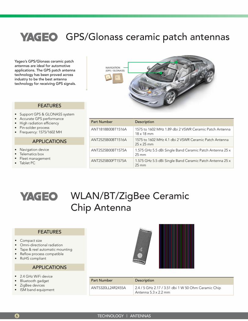
GPS/Glonass ceramic patch antennas
Yageo’s GPS/Glonass ceramic patch antennas are ideal for automotive applications. The GPS patch antenna technology has been proved across industry to be the best antenna technology for receiving GPS signals.
FEATURES
Support GPS & GLONASS systemAccurate GPS performance High radiation efficiency Pin-solder processFrequency: 1575/1602 MH
••
•
APPLICATIONS
Navigation deviceTelematics boxFleet managementTablet PC
••••
••
WLAN/BT/ZigBee Ceramic Chip Antenna
Part Number Description
ANT1818B00BT1516A 1575 to 1602 MHz 1.89 dbi 2 VSWR Ceramic Patch Antenna 18 x 18 mm
ANT2525B00BT1516A 1575 to 1602 MHz 4.1 dbi 2 VSWR Ceramic Patch Antenna 25 x 25 mm
ANT2525B00BT1575A 1.575 GHz 5.5 dBi Single Band Ceramic Patch Antenna 25 x 25 mm
ANT2525B00FT1575A 1.575 GHz 5.5 dBi Single Band Ceramic Patch Antenna 25 x 25 mm
FEATURES
••
•
••
Compact size Omni-directional radiation Tape & reel automatic mounting Reflow process compatible RoHS compliant
APPLICATIONS
2.4 GHz WiFi device Bluetooth gadget ZigBee devices ISM band equipment
••••
Part Number Description
ANT5320LL24R2455A 2.4 / 5 GHz 2.17 / 3.51 dbi 1 W 50 Ohm Ceramic Chip Antenna 5.3 x 2.2 mm
ISSU
E 01
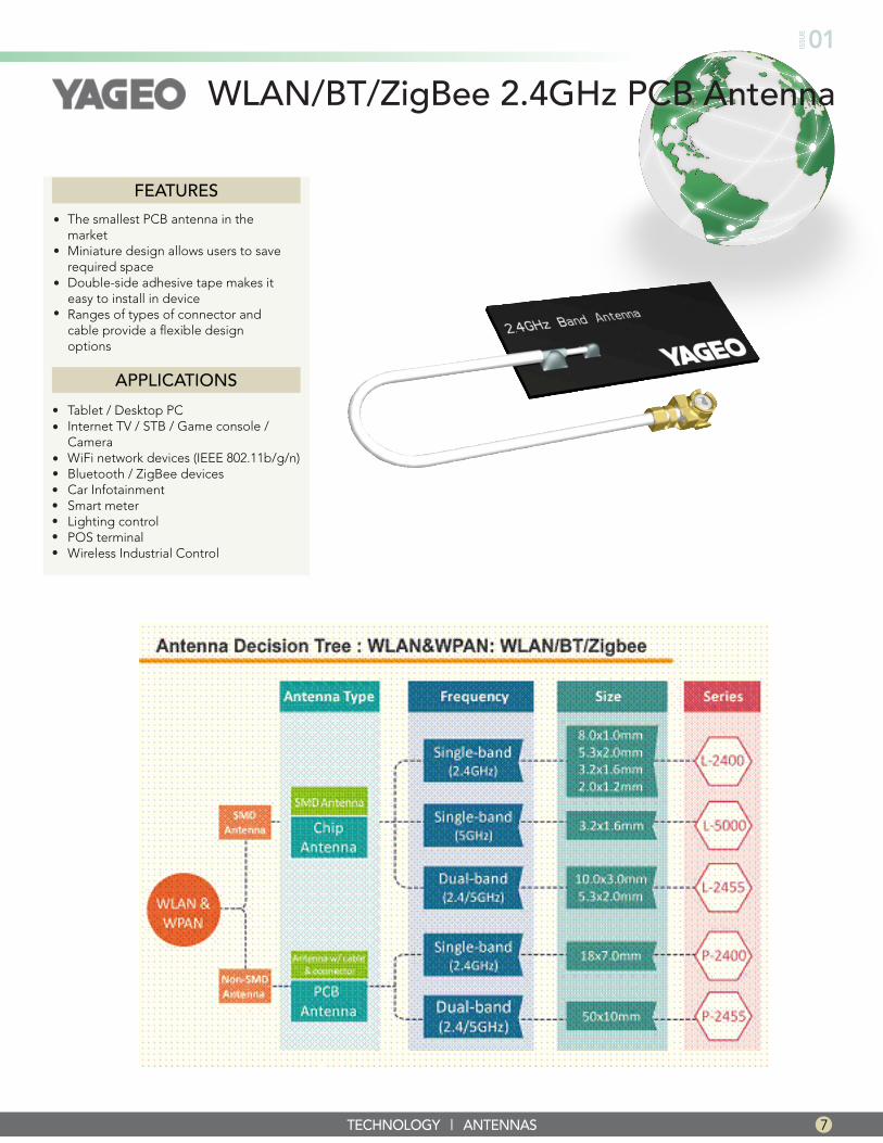
WLAN/BT/ZigBee 2.4GHz PCB Antenna
7TECHNOLOGY | ANTENNAS
FEATURES
The smallest PCB antenna in the marketMiniature design allows users to save required space Double-side adhesive tape makes it easy to install in deviceRanges of types of connector and cable provide a flexible design options
•
•
•
•
APPLICATIONS
Tablet / Desktop PC Internet TV / STB / Game console / Camera WiFi network devices (IEEE 802.11b/g/n)Bluetooth / ZigBee devicesCar InfotainmentSmart meterLighting controlPOS terminalWireless Industrial Control
••
•••••••
Smart About Bluetooth® Smart
Bluetooth® Smart wireless technology is the new ultra-power efficient, app-friendly version of Bluetooth® transforming the low power wireless industry. This technology is rapidly opening new opportunities and applications in industry verticals from consumer electronics, medical devices and home automation to retail and wearables. We at the Future Connectivity Solutions (FCS) group are dedicated to providing Bluetooth® Smart solutions to meet the rapid growth and demand in the low power wireless market. FCS is partners with STMicroelectronics, Dialog Semiconductor, Murata, Panasonic, Cypress Semiconductor and Microchip Technology to provide the latest and fastest time to market solutions. Bluetooth® Smart is also important technology in driving the Internet of Things (IoT), which has a strong focus from Future Electronics and the listed partners.
While the power efficiency of Bluetooth® Smart devices from various suppliers makes it perfect for devices needing to run off tiny batteries for long periods,
one of the big drivers of the technology behind Bluetooth® Smart is its ability to work with a wide variety of applications on smartphones or tablets consumers already own. The developer friendly Bluetooth® Smart architecture is now supported by all major operating systems natively. This makes it easy for developers to create apps that link with everyday objects like heart rate monitors, toothbrushes, and even shoes. With Bluetooth® Smart, developers are only limited by their imaginations. In a 2013 market research
By: Allen Cabreros, Advanced Engineer Future Electronics
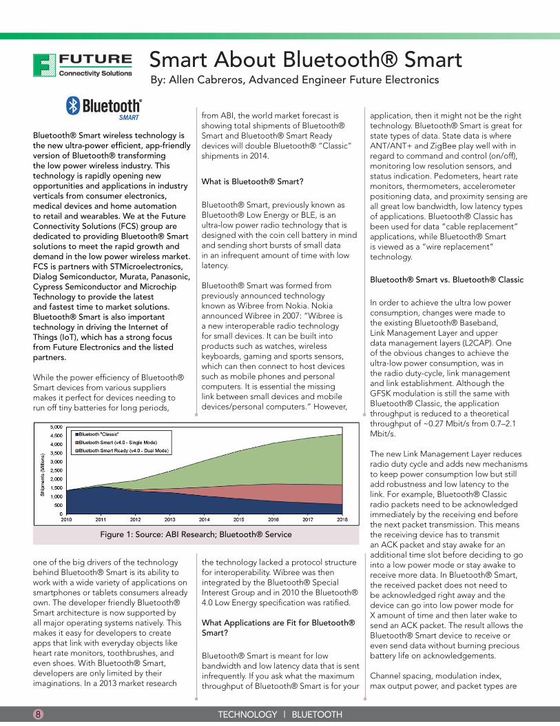
from ABI, the world market forecast is showing total shipments of Bluetooth® Smart and Bluetooth® Smart Ready devices will double Bluetooth® “Classic” shipments in 2014.
What is Bluetooth® Smart?
Bluetooth® Smart, previously known as Bluetooth® Low Energy or BLE, is an ultra-low power radio technology that is designed with the coin cell battery in mind and sending short bursts of small data in an infrequent amount of time with low latency.
Bluetooth® Smart was formed from previously announced technology known as Wibree from Nokia. Nokia announced Wibree in 2007: “Wibree is a new interoperable radio technology for small devices. It can be built into products such as watches, wireless keyboards, gaming and sports sensors, which can then connect to host devices such as mobile phones and personal computers. It is essential the missing link between small devices and mobile devices/personal computers.” However,
the technology lacked a protocol structure for interoperability. Wibree was then integrated by the Bluetooth® Special Interest Group and in 2010 the Bluetooth® 4.0 Low Energy specification was ratified.
What Applications are Fit for Bluetooth® Smart?
Bluetooth® Smart is meant for low bandwidth and low latency data that is sent infrequently. If you ask what the maximum throughput of Bluetooth® Smart is for your
application, then it might not be the right technology. Bluetooth® Smart is great for state types of data. State data is where ANT/ANT+ and ZigBee play well with in regard to command and control (on/off), monitoring low resolution sensors, and status indication. Pedometers, heart rate monitors, thermometers, accelerometer positioning data, and proximity sensing are all great low bandwidth, low latency types of applications. Bluetooth® Classic has been used for data “cable replacement” applications, while Bluetooth® Smart is viewed as a “wire replacement” technology.
Bluetooth® Smart vs. Bluetooth® Classic
In order to achieve the ultra low power consumption, changes were made to the existing Bluetooth® Baseband, Link Management Layer and upper data management layers (L2CAP). One of the obvious changes to achieve the ultra-low power consumption, was in the radio duty-cycle, link management and link establishment. Although the GFSK modulation is still the same with Bluetooth® Classic, the application throughput is reduced to a theoretical throughput of ~0.27 Mbit/s from 0.7–2.1 Mbit/s.
The new Link Management Layer reduces radio duty cycle and adds new mechanisms to keep power consumption low but still add robustness and low latency to the link. For example, Bluetooth® Classic radio packets need to be acknowledged immediately by the receiving end before the next packet transmission. This means the receiving device has to transmit an ACK packet and stay awake for an additional time slot before deciding to go into a low power mode or stay awake to receive more data. In Bluetooth® Smart, the received packet does not need to be acknowledged right away and the device can go into low power mode for X amount of time and then later wake to send an ACK packet. The result allows the Bluetooth® Smart device to receive or even send data without burning precious battery life on acknowledgements.
Channel spacing, modulation index, max output power, and packet types are
Figure 1: Source: ABI Research; Bluetooth® Service
8 TECHNOLOGY | BLUETOOTH
ISSU
E 01
9
other items that have changed to with Bluetooth® Smart. This means Bluetooth® Classic is not compatible with Bluetooth® Smart. Only Bluetooth® Smart and Bluetooth® Smart Ready devices can communicate with each other. Bluetooth® Smart Ready devices support both Bluetooth® Classic and Bluetooth® Smart, making it a dual mode device. There are new Smart Ready devices emerging quickly in the market today. Apple iPhone 4S and later, iPad 3 and later, recent Macbooks, Android devices and PC laptops are just a few devices that are Smart Ready today.
New Roles and Data Modes
Bluetooth® Smart also defines new roles and device types. This is similar to the Master and Slave roles in Bluetooth® Classic. There are Central and Peripheral device role types within Bluetooth® Smart. Roles are defined in profiles and how services can be provided between Bluetooth® Smart and Bluetooth® Smart Ready devices. However, any device can be either role and switch between them.
A Central device’s role performs the function of discovering, connecting and accessing the available services from the Peripheral device. Smartphones, Tablets, PCs are typically the Central device as they have displays and user interfaces to discover, connect, and view data and services from Peripheral devices.
A Peripheral device role performs functions such as advertisements, being discoverable and connectable to Central devices, and providing services. Typical Peripheral devices today are keyfobs, fitbits, watches, temperature sensors, mice or keyboard. Peripheral devices are typically Bluetooth® Smart only devices
and would be battery powered.
Advertisement Mode
One of the big advantages of Bluetooth® Smart is the ability to advertize and broadcast data without the need of establishing a complete connection. Establishing a complete connection would require a higher radio duty cycle consume more power. Some applications and data can use this advertisement mode to save power and do not require a bidirectional
full duplex RF link. One example is a temperature sensor where temperature can be broadcasted periodically. A Central device would not need to create a full connection to the Peripheral device to obtain this small amount of temperature data.
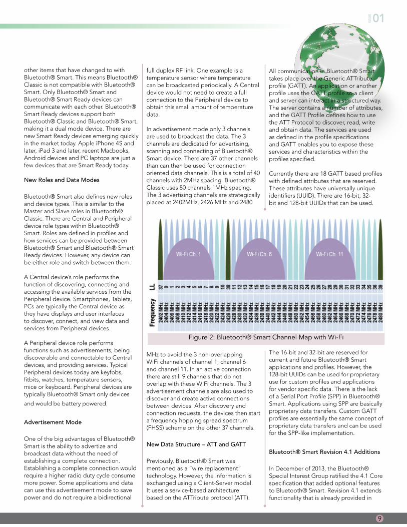
In advertisement mode only 3 channels are used to broadcast the data. The 3 channels are dedicated for advertising, scanning and connecting of Bluetooth® Smart device. There are 37 other channels than can then be used for connection oriented data channels. This is a total of 40 channels with 2MHz spacing. Bluetooth® Classic uses 80 channels 1MHz spacing. The 3 advertising channels are strategically placed at 2402MHz, 2426 MHz and 2480
MHz to avoid the 3 non-overlapping WiFi channels of channel 1, channel 6 and channel 11. In an active connection there are still 9 channels that do not overlap with these WiFi channels. The 3 advertisement channels are also used to discover and create active connections between devices. After discovery and connection requests, the devices then start a frequency hopping spread spectrum (FHSS) scheme on the other 37 channels.
New Data Structure – ATT and GATT
Previously, Bluetooth® Smart was mentioned as a “wire replacement” technology. However, the information is exchanged using a Client-Server model. It uses a service-based architecture based on the ATTribute protocol (ATT).
Figure 2: Bluetooth® Smart Channel Map with Wi-Fi
All communication in Bluetooth® Smart takes place over the Generic ATTribute profile (GATT). An application or another profile uses the GATT profile so a client and server can interact in a structured way. The server contains a number of attributes, and the GATT Profile defines how to use the ATT Protocol to discover, read, write and obtain data. The services are used as defined in the profile specifications and GATT enables you to expose these services and characteristics within the profiles specified.
Currently there are 18 GATT based profiles with defined attributes that are reserved. These attributes have universally unique identifiers (UUID). There are 16-bit, 32-bit and 128-bit UUIDs that can be used.
The 16-bit and 32-bit are reserved for current and future Bluetooth® Smart applications and profiles. However, the 128-bit UUIDs can be used for proprietary use for custom profiles and applications for vendor specific data. There is the lack of a Serial Port Profile (SPP) in Bluetooth® Smart. Applications using SPP are basically proprietary data transfers. Custom GATT profiles are essentially the same concept of proprietary data transfers and can be used for the SPP-like implementation.
Bluetooth® Smart Revision 4.1 Additions
In December of 2013, the Bluetooth® Special Interest Group ratified the 4.1 Core specification that added optional features to Bluetooth® Smart. Revision 4.1 extends functionality that is already provided in
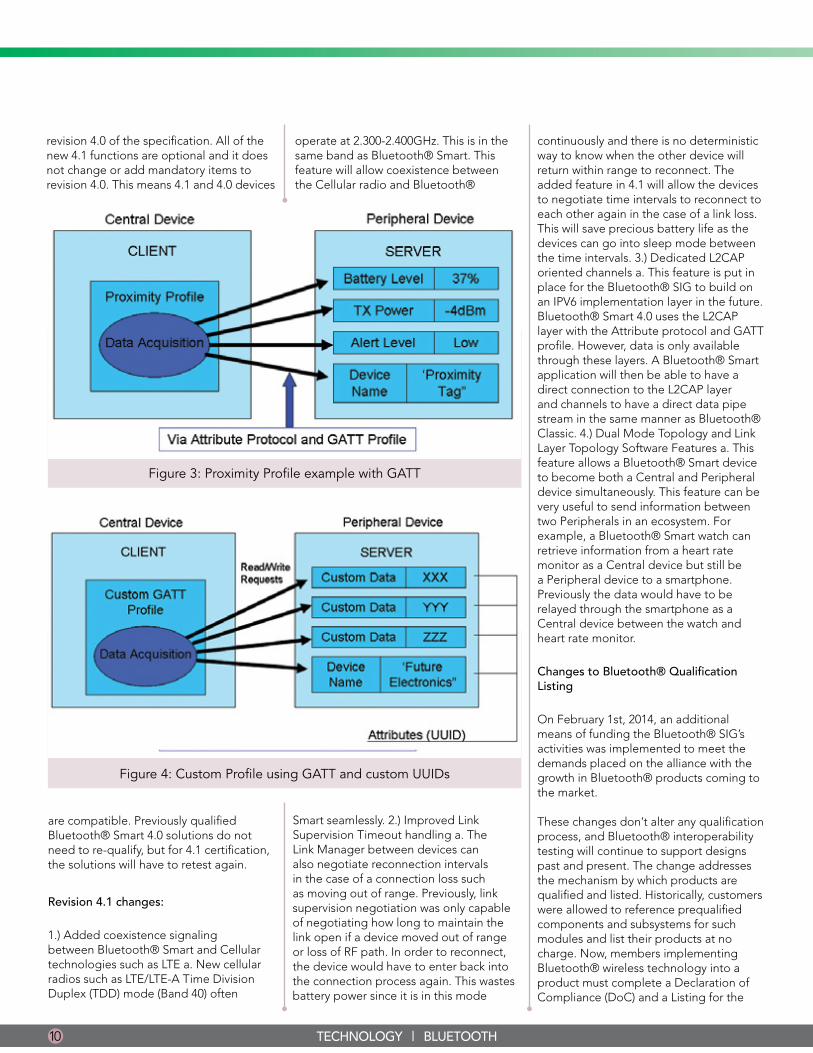
Figure 4: Custom Profile using GATT and custom UUIDs
Figure 3: Proximity Profile example with GATT
revision 4.0 of the specification. All of the new 4.1 functions are optional and it does not change or add mandatory items to revision 4.0. This means 4.1 and 4.0 devices
are compatible. Previously qualified Bluetooth® Smart 4.0 solutions do not need to re-qualify, but for 4.1 certification, the solutions will have to retest again.
Revision 4.1 changes:
1.) Added coexistence signaling between Bluetooth® Smart and Cellular technologies such as LTE a. New cellular radios such as LTE/LTE-A Time Division Duplex (TDD) mode (Band 40) often
operate at 2.300-2.400GHz. This is in the same band as Bluetooth® Smart. This feature will allow coexistence between the Cellular radio and Bluetooth®
Smart seamlessly. 2.) Improved Link Supervision Timeout handling a. The Link Manager between devices can also negotiate reconnection intervals in the case of a connection loss such as moving out of range. Previously, link supervision negotiation was only capable of negotiating how long to maintain the link open if a device moved out of range or loss of RF path. In order to reconnect, the device would have to enter back into the connection process again. This wastes battery power since it is in this mode
continuously and there is no deterministic way to know when the other device will return within range to reconnect. The added feature in 4.1 will allow the devices to negotiate time intervals to reconnect to each other again in the case of a link loss. This will save precious battery life as the devices can go into sleep mode between the time intervals. 3.) Dedicated L2CAP oriented channels a. This feature is put in place for the Bluetooth® SIG to build on an IPV6 implementation layer in the future. Bluetooth® Smart 4.0 uses the L2CAP layer with the Attribute protocol and GATT profile. However, data is only available through these layers. A Bluetooth® Smart application will then be able to have a direct connection to the L2CAP layer and channels to have a direct data pipe stream in the same manner as Bluetooth® Classic. 4.) Dual Mode Topology and Link Layer Topology Software Features a. This feature allows a Bluetooth® Smart device to become both a Central and Peripheral device simultaneously. This feature can be very useful to send information between two Peripherals in an ecosystem. For example, a Bluetooth® Smart watch can retrieve information from a heart rate monitor as a Central device but still be a Peripheral device to a smartphone. Previously the data would have to be relayed through the smartphone as a Central device between the watch and heart rate monitor.
Changes to Bluetooth® Qualification Listing
On February 1st, 2014, an additional means of funding the Bluetooth® SIG’s activities was implemented to meet the demands placed on the alliance with the growth in Bluetooth® products coming to the market.
These changes don’t alter any qualification process, and Bluetooth® interoperability testing will continue to support designs past and present. The change addresses the mechanism by which products are qualified and listed. Historically, customers were allowed to reference prequalified components and subsystems for such modules and list their products at no charge. Now, members implementing Bluetooth® wireless technology into a product must complete a Declaration of Compliance (DoC) and a Listing for the
10 TECHNOLOGY | BLUETOOTH

ISSU
E 01
Qualified Design they built, changed, used or branded. A Listing may include multiple products if each product implements the same Qualified Design referenced in the DoC. If a customer creates an OEM product that may be rebranded as another company or several other companies, then they too need to list the product themselves. An End Product Listing (EPL) can only be created by a Bluetooth® SIG member, and an EPL cannot be created by one member on behalf of another company.
The DoC and Listing is followed by a fee for the process. The fee ranges from $2K to $8K per EPL depending on the status of the Lister with the Bluetooth® SIG, Associate Member or Adopter, size and revenue of the Lister. The fees are not associated with Future Electronics or partners. This charge is directly implemented by the Bluetooth® SIG and is separate from the certification and testing costs. Although precertified Bluetooth® and Bluetooth® Smart solutions are available from Future Connectivity Solutions and our partners, the EPL fees still apply.
Solutions
We at Future Connectivity Solutions (FCS) are committed to providing the best and most efficient Bluetooth Smart solutions to our customers. Systems on Chip (SoC) and module solutions are available from FCS. These solutions are provided with ready-to-go Bluetooth Smart Protocol stacks that are pre-certified with easy profile and application development environments. Sizes are as small as 2.5mm x 2.5mm SoC to 5mm x 5mm fully certified modules. Solutions with 4mA peak with >600nA sleep modes are also available.
Modules and SoCs with integrated slow clocks, buck/boost, BALUN, antenna, with Bluetooth and FCC, IC, CE certification are available now. Roadmap products will integrate more features such as cap-touch IO, integrated accelerometer and MEMS sensors, M0+ apps processors and energy harvesting capabilities. Each solution will have a best fit in different types of Bluetooth Smart Devices. From something as simple as a temperature sensor to last 7 years off of a 180mAh CR2032 coin cell
11TECHNOLOGY | BLUETOOTH
battery to the latest network thermostat with multiple radios, FCS has solutions from the below vendors for Bluetooth Smart and Bluetooth Smart Ready applications.
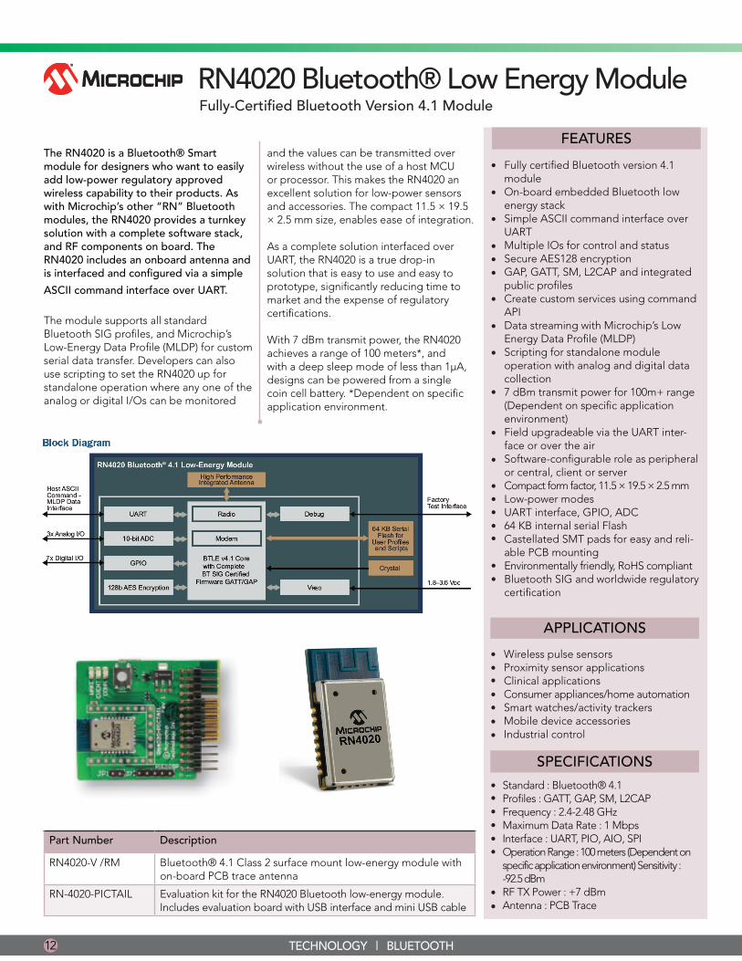
RN4020 Bluetooth® Low Energy ModuleFully-Certified Bluetooth Version 4.1 Module
The RN4020 is a Bluetooth® Smart module for designers who want to easily add low-power regulatory approved wireless capability to their products. As with Microchip’s other “RN” Bluetooth modules, the RN4020 provides a turnkey solution with a complete software stack, and RF components on board. The RN4020 includes an onboard antenna and is interfaced and configured via a simple
ASCII command interface over UART.
The module supports all standard Bluetooth SIG profiles, and Microchip’s Low-Energy Data Profile (MLDP) for custom serial data transfer. Developers can also use scripting to set the RN4020 up for standalone operation where any one of the analog or digital I/Os can be monitored
12 TECHNOLOGY | BLUETOOTH
Part Number Description
RN4020-V /RM Bluetooth® 4.1 Class 2 surface mount low-energy module with on-board PCB trace antenna
RN-4020-PICTAIL Evaluation kit for the RN4020 Bluetooth low-energy module. Includes evaluation board with USB interface and mini USB cable
APPLICATIONS
••••••
Wireless pulse sensors Proximity sensor applicationsClinical applicationsConsumer appliances/home automationSmart watches/activity trackersMobile device accessoriesIndustrial control•
SPECIFICATIONS
Standard : Bluetooth® 4.1Profiles : GATT, GAP, SM, L2CAP Frequency : 2.4-2.48 GHzMaximum Data Rate : 1 MbpsInterface : UART, PIO, AIO, SPI Operation Range : 100 meters (Dependent on specific application environment) Sensitivity : -92.5 dBm RF TX Power : +7 dBmAntenna : PCB Trace
••••••
••
FEATURES
•
•
•
•
•
Fully certified Bluetooth version 4.1 moduleOn-board embedded Bluetooth low energy stackSimple ASCII command interface over UARTMultiple IOs for control and statusSecure AES128 encryptionGAP, GATT, SM, L2CAP and integrated public profilesCreate custom services using command APIData streaming with Microchip’s Low Energy Data Profile (MLDP)Scripting for standalone module operation with analog and digital data collection7 dBm transmit power for 100m+ range (Dependent on specific application environment)Field upgradeable via the UART inter-face or over the airSoftware-configurable role as peripheral or central, client or serverCompact form factor, 11.5 × 19.5 × 2.5 mmLow-power modesUART interface, GPIO, ADC64 KB internal serial FlashCastellated SMT pads for easy and reli-able PCB mounting Environmentally friendly, RoHS compliantBluetooth SIG and worldwide regulatory certification
•
•
•
•
•
•
•
•••••
••
and the values can be transmitted over wireless without the use of a host MCU or processor. This makes the RN4020 an excellent solution for low-power sensors and accessories. The compact 11.5 × 19.5 × 2.5 mm size, enables ease of integration.
As a complete solution interfaced over UART, the RN4020 is a true drop-in solution that is easy to use and easy to prototype, significantly reducing time to market and the expense of regulatory certifications.
With 7 dBm transmit power, the RN4020 achieves a range of 100 meters*, and with a deep sleep mode of less than 1µA, designs can be powered from a single coin cell battery. *Dependent on specific application environment.
ISSU
E 01
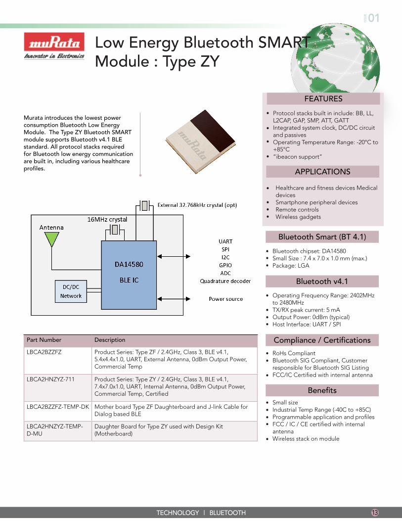
Low Energy Bluetooth SMART Module : Type ZY
Murata introduces the lowest power consumption Bluetooth Low Energy Module. The Type ZY Bluetooth SMART module supports Bluetooth v4.1 BLE standard. All protocol stacks required for Bluetooth low energy communication are built in, including various healthcare profiles.
13TECHNOLOGY | BLUETOOTH
Part Number Description
LBCA2BZZFZ Product Series: Type ZF / 2.4GHz, Class 3, BLE v4.1, 5.4x4.4x1.0, UART, External Antenna, 0dBm Output Power, Commercial Temp
LBCA2HNZYZ-711 Product Series: Type ZY / 2.4GHz, Class 3, BLE v4.1, 7.4x7.0x1.0, UART, Internal Antenna, 0dBm Output Power, Commercial Temp, Certified
LBCA2BZZFZ-TEMP-DK Mother board Type ZF Daughterboard and J-link Cable for Dialog based BLE
LBCA2HNZYZ-TEMP-D-MU
Daughter Board for Type ZY used with Design Kit (Motherboard)
FEATURES
APPLICATIONS
Protocol stacks built in include: BB, LL, L2CAP, GAP, SMP, ATT, GATT Integrated system clock, DC/DC circuit and passivesOperating Temperature Range: -20°C to +85°C “ibeacon support”
•
•
•
•
Healthcare and fitness devices Medical devices Smartphone peripheral devices Remote controls Wireless gadgets
•
•••
Bluetooth chipset: DA14580Small Size : 7.4 x 7.0 x 1.0 mm (max.) Package: LGA
Operating Frequency Range: 2402MHz to 2480MHz TX/RX peak current: 5 mAOutput Power: 0dBm (typical)Host Interface: UART / SPI
RoHs CompliantBluetooth SIG Compliant, Customer responsible for Bluetooth SIG ListingFCC/IC Certified with internal antenna
Small size Industrial Temp Range (-40C to +85C) Programmable application and profiles FCC / IC / CE certified with internal antenna Wireless stack on module
•••
•
•••
••
•
••••
•
Bluetooth Smart (BT 4.1)
Bluetooth v4.1
Compliance / Certifications
Benefits
PAN1026 ETU Development Module
14 TECHNOLOGY | BLUETOOTH
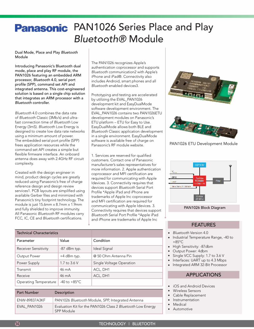
PAN1026 Series Place and Play Bluetooth® Module
Dual Mode, Place and Play Bluetooth Module
Introducing Panasonic’s Bluetooth dual mode, place and play RF module, the PAN1026 featuring an embedded ARM processor, Bluetooth 4.0, serial port profile (SPP), command set API and integrated antenna. This cost-engineered solution is based on a single chip solution that integrates an ARM processor with a Bluetooth controller.
Bluetooth 4.0 combines the data rate of Bluetooth Classic (3Mb/s) and ultra-fast connection time of Bluetooth Low Energy (3mS). Bluetooth Low Energy is designed to create low data rate networks using a minimum amount of power. The embedded serial port profile (SPP) frees application resources while the command set API creates a simple but flexible firmware interface. An onboard antenna does away with 2.4GHz RF circuit complexity.
Created with the design engineer in mind, product design cycles are greatly reduced using Panasonic’s free of charge reference design and design review services1. PCB layouts are simplified using available Gerber files and minimized with Panasonic’s tiny footprint technology. The module is just 15.6mm x 8.7mm x 1.9mm and fully shielded to improve immunity. All Panasonic Bluetooth RF modules carry FCC, IC, CE and Bluetooth certifications.
The PAN1026 recognizes Apple’s authentication coprocessor and supports Bluetooth communication2 with Apple’s iPhone and iPad®. Connectivity also includes Android, smart phones and all Bluetooth enabled devices3.
Prototyping and testing are accelerated by utilizing the EVAL_PAN1026 development kit and EasyDualMode software development environment. The EVAL_PAN1026 contains two PAN1026ETU development modules on Panasonic’s ETU platform – ETU for Easy to Use. EasyDualMode allows both BLE and Bluetooth Classic application development in a single environment. EasyDualMode software is available free of charge on Panasonic’s RF module website.
1. Services are reserved for qualified customers. Contact one of Panasonic manufacturer’s sales representatives for more information. 2. Apple authentication coprocessor and MFI certification are required for communicating with Apple Idevices. 3. Connectivity requires that devices support Bluetooth Serial Port Profile *Apple iPad and iPhone are trademarks of Apple Inc coprocessor and MFI certification are required for communicating with Apple Idevices. 3. Connectivity requires that devices support Bluetooth Serial Port Profile *Apple iPad and iPhone are trademarks of Apple Inc
PAN1026 Block Diagram
Part Number Description
ENW-89837A3KF PAN1026 Bluetooth Module, SPP, Integrated Antenna
EVAL_PAN1026 Evaluation Kit for the PAN1026 Class 2 Bluetooth Low Energy SPP Module
FEATURES
Bluetooth Version 4.0Industrial Temperature Range, -40 to +85°CHigh Sensitivity: -87dbmOutput Power: 4dbmSingle VCC Supply: 1.7 to 3.6 VInterfaces: UART up to 4.3 MbpsIntegrated ARM 32-Bit Processor
••
•••••
APPLICATIONS
iOS and Android DevicesWireless SensorsCable ReplacementInstrumentationMedicalAutomotive
••••••
Technical Characteristics
Parameter Value Condition
Receiver Sensitivity -87 dBm typ. Ideal Signal
Output Power +4 dBm typ. @ 50 Ohm Antenna Pin
Power Supply 1.7 to 3.6 V Single Voltage Operation
Transmit 46 mA ACL, DH1
Receive 46 mA ACL, DH1
Operating Temperature -40 to +85°C
ISSU
E 01
15TECHNOLOGY | BLUETOOTH
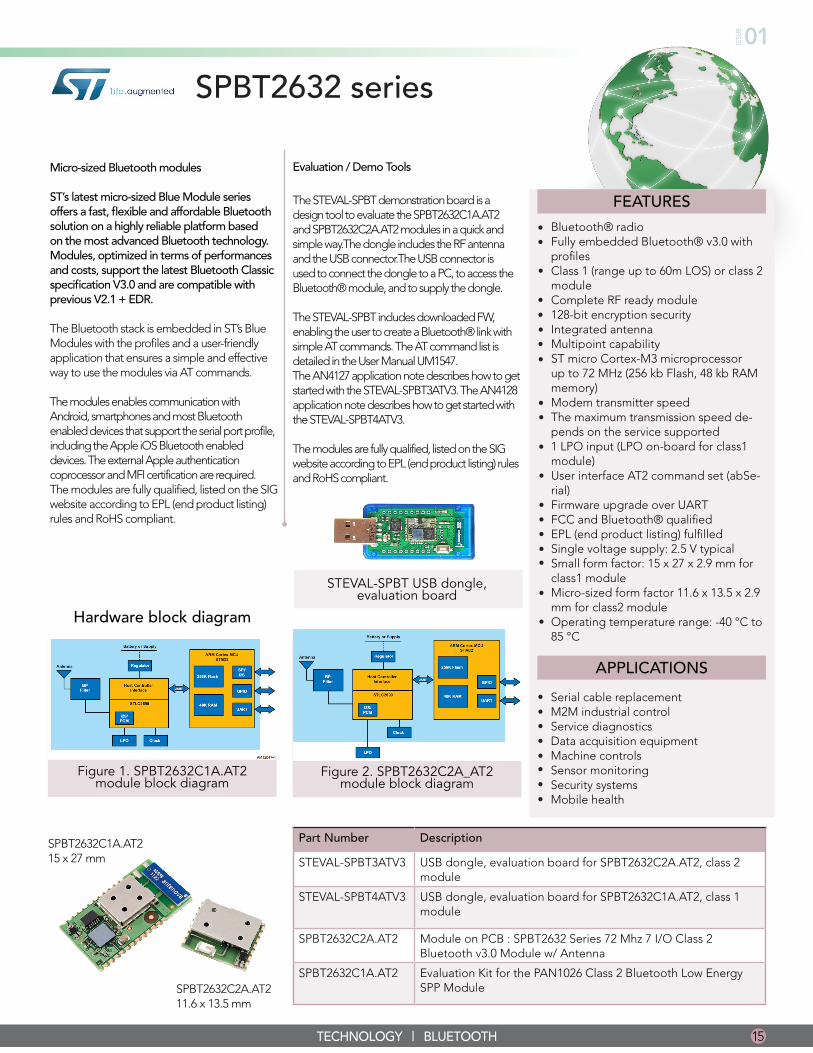
Micro-sized Bluetooth modules
ST’s latest micro-sized Blue Module series offers a fast, flexible and affordable Bluetooth solution on a highly reliable platform based on the most advanced Bluetooth technology. Modules, optimized in terms of performances and costs, support the latest Bluetooth Classic specification V3.0 and are compatible with previous V2.1 + EDR.
The Bluetooth stack is embedded in ST’s Blue Modules with the profiles and a user-friendly application that ensures a simple and effective way to use the modules via AT commands.
The modules enables communication with Android, smartphones and most Bluetooth enabled devices that support the serial port profile, including the Apple iOS Bluetooth enabled devices. The external Apple authentication coprocessor and MFI certification are required.The modules are fully qualified, listed on the SIG website according to EPL (end product listing) rules and RoHS compliant.
SPBT2632C1A.AT2 15 x 27 mm
SPBT2632C2A.AT2 11.6 x 13.5 mm
SPBT2632 series
Evaluation / Demo Tools
The STEVAL-SPBT demonstration board is a design tool to evaluate the SPBT2632C1A.AT2 and SPBT2632C2A.AT2 modules in a quick and simple way.The dongle includes the RF antenna and the USB connector.The USB connector is used to connect the dongle to a PC, to access the Bluetooth® module, and to supply the dongle.
The STEVAL-SPBT includes downloaded FW, enabling the user to create a Bluetooth® link with simple AT commands. The AT command list is detailed in the User Manual UM1547. The AN4127 application note describes how to get started with the STEVAL-SPBT3ATV3. The AN4128 application note describes how to get started with the STEVAL-SPBT4ATV3.
The modules are fully qualified, listed on the SIG website according to EPL (end product listing) rules and RoHS compliant.
Figure 1. SPBT2632C1A.AT2 module block diagram
Hardware block diagram
Figure 2. SPBT2632C2A_AT2 module block diagram
STEVAL-SPBT USB dongle, evaluation board
FEATURES
••
•
••
•
•
Bluetooth® radio Fully embedded Bluetooth® v3.0 with profiles Class 1 (range up to 60m LOS) or class 2 module Complete RF ready module128-bit encryption securityIntegrated antennaMultipoint capabilityST micro Cortex-M3 microprocessor up to 72 MHz (256 kb Flash, 48 kb RAM memory)Modem transmitter speedThe maximum transmission speed de-pends on the service supported1 LPO input (LPO on-board for class1 module)User interface AT2 command set (abSe-rial)Firmware upgrade over UARTFCC and Bluetooth® qualifiedEPL (end product listing) fulfilledSingle voltage supply: 2.5 V typicalSmall form factor: 15 x 27 x 2.9 mm for class1 moduleMicro-sized form factor 11.6 x 13.5 x 2.9 mm for class2 moduleOperating temperature range: -40 °C to 85 °C
•
•
•
•
•
•••••
•
•
APPLICATIONS
Serial cable replacement M2M industrial control Service diagnostics Data acquisition equipment Machine controls Sensor monitoring Security systems Mobile health
••••••••
Part Number Description
STEVAL-SPBT3ATV3 USB dongle, evaluation board for SPBT2632C2A.AT2, class 2 module
STEVAL-SPBT4ATV3 USB dongle, evaluation board for SPBT2632C1A.AT2, class 1 module
SPBT2632C2A.AT2 Module on PCB : SPBT2632 Series 72 Mhz 7 I/O Class 2 Bluetooth v3.0 Module w/ Antenna
SPBT2632C1A.AT2 Evaluation Kit for the PAN1026 Class 2 Bluetooth Low Energy SPP Module
16 TECHNOLOGY | CELLULAR
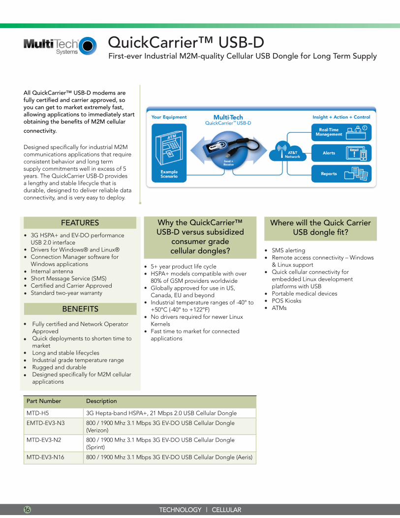
All QuickCarrier™ USB-D modems are fully certified and carrier approved, so you can get to market extremely fast, allowing applications to immediately start obtaining the benefits of M2M cellular
connectivity.
Designed specifically for industrial M2M communications applications that require consistent behavior and long term supply commitments well in excess of 5 years. The QuickCarrier USB-D provides a lengthy and stable lifecycle that is durable, designed to deliver reliable data connectivity, and is very easy to deploy.
QuickCarrier™ USB-D
FEATURES
3G HSPA+ and EV-DO performanceUSB 2.0 interface Drivers for Windows® and Linux®Connection Manager software for Windows applicationsInternal antennaShort Message Service (SMS)Certified and Carrier Approved Standard two-year warranty
•
••
••••
BENEFITS
Fully certified and Network Operator Approved Quick deployments to shorten time to market Long and stable lifecyclesIndustrial grade temperature rangeRugged and durable Designed specifically for M2M cellular applications
•
•
••••
5+ year product life cycleHSPA+ models compatible with over 80% of GSM providers worldwideGlobally approved for use in US, Canada, EU and beyondIndustrial temperature ranges of -40° to +50°C (-40° to +122°F)No drivers required for newer Linux KernelsFast time to market for connected applications
••
•
•
•
•
Part Number Description
MTD-H5 3G Hepta-band HSPA+, 21 Mbps 2.0 USB Cellular Dongle
EMTD-EV3-N3 800 / 1900 Mhz 3.1 Mbps 3G EV-DO USB Cellular Dongle (Verizon)
MTD-EV3-N2 800 / 1900 Mhz 3.1 Mbps 3G EV-DO USB Cellular Dongle (Sprint)
MTD-EV3-N16 800 / 1900 Mhz 3.1 Mbps 3G EV-DO USB Cellular Dongle (Aeris)
First-ever Industrial M2M-quality Cellular USB Dongle for Long Term Supply
Why the QuickCarrier™ USB-D versus subsidized
consumer grade cellular dongles? SMS alerting
Remote access connectivity – Windows & Linux supportQuick cellular connectivity for embedded Linux development platforms with USBPortable medical devicesPOS KiosksATMs
••
•
•••
Where will the Quick Carrier USB dongle fit?
ISSU
E 01
17TECHNOLOGY | CELLULAR
Technical Specifications
Model MTD-H5 MTD-EV3
Performance HSPA+ EV-DO
Frequency Band 3G: Hepta-band 800/850/900/AWS 1700/1900/2100 MHz 2G: Quad-band 850/900/1800/1900 MHz
Dual-band 800/1900 MHz
Packet Data* Up to 21.0 Mbps downlink Up to 5.76 Mbps uplink Up to 3.1 Mbps downlink Up to 1.8 Mbps uplink
SMS Point-to-Point Messaging, Mobile-Terminated SMS, Mobile-Originated SMS
Point-to-Point Messaging, Mobile-Terminated SMS, Mobile-Originated SMS
USB USB 2.0 High Speed Compatible USB 2.0 High Speed Compatible
IP Protocols TCP/UDP/FTP/SMTP TCP/UDP/FTP/SMTP
Operating Voltage 5V via USB Bus 5V via USB Bus
Connectors
SIM Connector Mini SIM; 1.8 and 3V N/A
Physical Description
Physical Dimensions (L x W x H)
3.1” x 1.58 x 0.74” (7.87 cm x 1.88 cm) Includes 7” (17.3 cm) integrated USB cable
3.1” x 1.58 x 0.74” (7.87 cm x 4.01 cm x 1.88cm) Includes 10.5” (26.5 cm) integrated USB cable
Environmental
Operating Temperature -40º to +122º F (-40º to +50ºC) -40º to +122º F (-40º to +50ºC)
Storage Temperature -40º to +185º F (-40º to +85ºC) -40º to +185º F (-40º to +85ºC)
Humidity Relative humidity 15% to 93% noncondensing Relative humidity 15% to 93% noncondensing
Certifications
Regulatory FCC Part 15 Class B (US), IC (Canada), R&TTE (EU Economic Area)
FCC Part 15 Class B (US)
Safety UL60950-1 (US), cUL60950-1 (Canada), IEC60950-1 (EU Economic Area)
UL60950-1 (US)
Network AT&T, T-Mobile, Rogers, EU Carriers Pending: Bell, Telus
Verizon, Sprint, Aeris
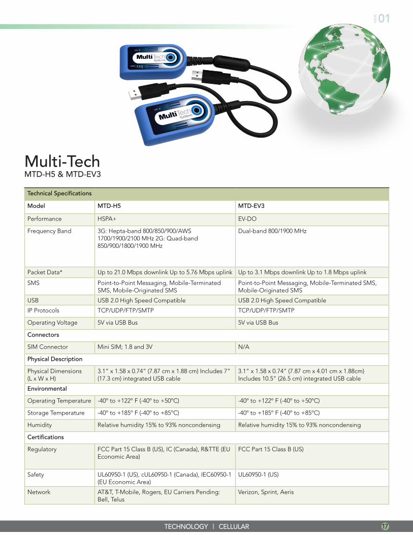
Multi-TechMTD-H5 & MTD-EV3
18 TECHNOLOGY | CELLULAR
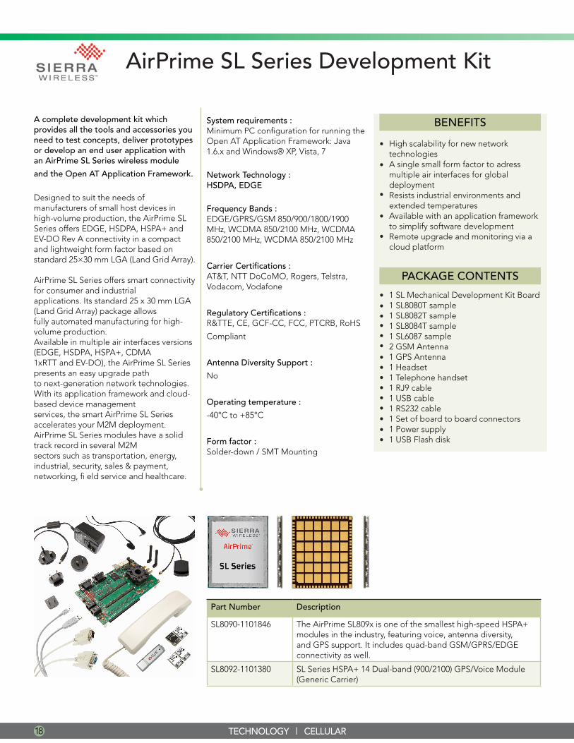
AirPrime SL Series Development Kit
A complete development kit which provides all the tools and accessories you need to test concepts, deliver prototypes or develop an end user application with an AirPrime SL Series wireless module
and the Open AT Application Framework.
Designed to suit the needs of manufacturers of small host devices in high-volume production, the AirPrime SL Series offers EDGE, HSDPA, HSPA+ and EV-DO Rev A connectivity in a compact and lightweight form factor based on standard 25×30 mm LGA (Land Grid Array).
AirPrime SL Series offers smart connectivity for consumer and industrialapplications. Its standard 25 x 30 mm LGA (Land Grid Array) package allowsfully automated manufacturing for high-volume production.Available in multiple air interfaces versions (EDGE, HSDPA, HSPA+, CDMA1xRTT and EV-DO), the AirPrime SL Series presents an easy upgrade pathto next-generation network technologies.With its application framework and cloud-based device managementservices, the smart AirPrime SL Series accelerates your M2M deployment.AirPrime SL Series modules have a solid track record in several M2Msectors such as transportation, energy, industrial, security, sales & payment,networking, fi eld service and healthcare.
Part Number Description
SL8090-1101846 The AirPrime SL809x is one of the smallest high-speed HSPA+ modules in the industry, featuring voice, antenna diversity, and GPS support. It includes quad-band GSM/GPRS/EDGE connectivity as well.
SL8092-1101380 SL Series HSPA+ 14 Dual-band (900/2100) GPS/Voice Module (Generic Carrier)
System requirements :Minimum PC configuration for running the Open AT Application Framework: Java 1.6.x and Windows® XP, Vista, 7
Network Technology :HSDPA, EDGE
Frequency Bands :EDGE/GPRS/GSM 850/900/1800/1900 MHz, WCDMA 850/2100 MHz, WCDMA 850/2100 MHz, WCDMA 850/2100 MHz
Carrier Certifications :AT&T, NTT DoCoMO, Rogers, Telstra, Vodacom, Vodafone
Regulatory Certifications :R&TTE, CE, GCF-CC, FCC, PTCRB, RoHS
Compliant
Antenna Diversity Support :
No
Operating temperature :
-40°C to +85°C
Form factor :Solder-down / SMT Mounting
1 SL Mechanical Development Kit Board1 SL8080T sample1 SL8082T sample1 SL8084T sample1 SL6087 sample2 GSM Antenna1 GPS Antenna1 Headset1 Telephone handset1 RJ9 cable1 USB cable1 RS232 cable1 Set of board to board connectors1 Power supply1 USB Flash disk
•••••••••••••••
BENEFITS
High scalability for new networktechnologiesA single small form factor to adressmultiple air interfaces for globaldeploymentResists industrial environments andextended temperaturesAvailable with an application frameworkto simplify software developmentRemote upgrade and monitoring via acloud platform
•
•
•
•
•
PACKAGE CONTENTS
ISSU
E 01
19TECHNOLOGY | GPC / GNSS
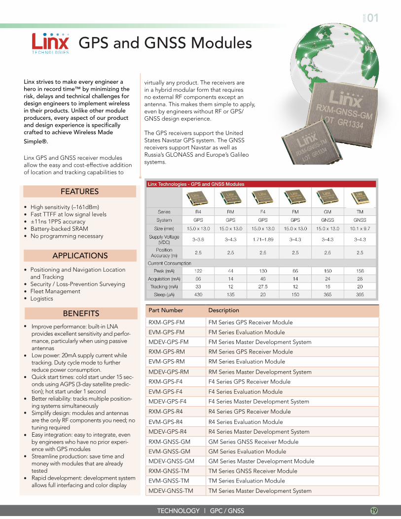
GPS and GNSS Modules
Linx strives to make every engineer a hero in record time™ by minimizing the risk, delays and technical challenges for design engineers to implement wireless in their products. Unlike other module producers, every aspect of our product and design experience is specifically crafted to achieve Wireless Made
Simple®.
Linx GPS and GNSS receiver modules allow the easy and cost-effective addition of location and tracking capabilities to
FEATURES
APPLICATIONS
High sensitivity (–161dBm)Fast TTFF at low signal levels±11ns 1PPS accuracyBattery-backed SRAMNo programming necessary
•••••
Positioning and Navigation Location and Tracking Security / Loss-Prevention Surveying Fleet Management Logistics
•
•••
Part Number Description
RXM-GPS-FM FM Series GPS Receiver Module
EVM-GPS-FM FM Series Evaluation Module
MDEV-GPS-FM FM Series Master Development System
RXM-GPS-RM RM Series GPS Receiver Module
EVM-GPS-RM RM Series Evaluation Module
MDEV-GPS-RM RM Series Master Development System
RXM-GPS-F4 F4 Series GPS Receiver Module
EVM-GPS-F4 F4 Series Evaluation Module
MDEV-GPS-F4 F4 Series Master Development System
RXM-GPS-R4 R4 Series GPS Receiver Module
EVM-GPS-R4 R4 Series Evaluation Module
MDEV-GPS-R4 R4 Series Master Development System
RXM-GNSS-GM GM Series GNSS Receiver Module
EVM-GNSS-GM GM Series Evaluation Module
MDEV-GNSS-GM GM Series Master Development Module
RXM-GNSS-TM TM Series GNSS Receiver Module
EVM-GNSS-TM TM Series Evaluation Module
MDEV-GNSS-TM TM Series Master Development System
Improve performance: built-in LNA provides excellent sensitivity and perfor-mance, particularly when using passive antennasLow power: 20mA supply current while tracking. Duty cycle mode to further reduce power consumption.Quick start times: cold start under 15 sec-onds using AGPS (3-day satellite predic-tion); hot start under 1 secondBetter reliability: tracks multiple position-ing systems simultaneouslySimplify design: modules and antennas are the only RF components you need; no tuning requiredEasy integration: easy to integrate, even by engineers who have no prior experi-ence with GPS modulesStreamline production: save time and money with modules that are already testedRapid development: development system allows full interfacing and color display
BENEFITS•
•
•
•
•
•
virtually any product. The receivers are in a hybrid modular form that requires no external RF components except an antenna. This makes them simple to apply, even by engineers without RF or GPS/GNSS design experience.
The GPS receivers support the United States Navstar GPS system. The GNSS receivers support Navstar as well as Russia’s GLONASS and Europe’s Galileo systems.
•
•
20 TECHNOLOGY | Wi-Fi
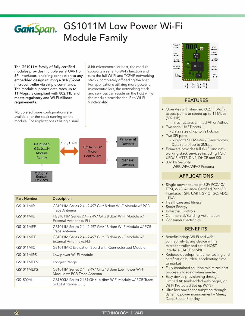
GS1011M Low Power Wi-Fi Module Family
The GS1011M family of fully certified modules provides multiple serial UART or SPI interfaces, enabling connection to any embedded design utilizing a 8/16/32-bit microcontroller via simple commands. The module supports data rates up to 11 Mbps, is compliant with 802.11b and meets regulatory and Wi-Fi Alliance requirements.
Multiple software configurations are available for the stack running on the module. For applications utilizing a small
Part Number Description
GS1011MIP GS1011M Series 2.4 - 2.497 GHz 8 dbm Wi-F Module w/ PCB Trace Antenna
GS1011MIE FGS1011M Series 2.4 - 2.497 GHz 8 dbm Wi-F Module w/ External Antenna (u.FL)
GS1011MEP GS1011M Series 2.4 - 2.497 GHz 18 dbm Wi-F Module w/ PCB Trace Antenna
GS1011MEE GS1011M Series 2.4 - 2.497 GHz 18 dbm Wi-F Module w/ External Antenna (u.FL)
GS1011MIC GS1011MIC Evaluation Board with Connectorized Module
GS1011MIPS Low power Wi-Fi module
GS1011MEES Longest Range
GS1011MEPS GS1011M Series 2.4 - 2.497 GHz 18 dbm Low Power Wi-F Module w/ PCB Trace Antenna
GS1500M GS1500M Series 2.484 GHz 14 dbm WiFi Module w/ PCB Trace or Ext Antenna (uFL)
FEATURES
•
•
•
•
Operates with standard 802.11 b/g/n access points at speed up to 11 Mbps (802.11b) - Infrastructure, Limited AP or AdhocTwo serial UART ports - Data rates of up to 921.6kbpsTwo SPI ports - Supports SPI Master / Slave modes - Data rate of up to 3MbpsFirmware provides full Wi-Fi and net-working stack services including TCP/UPD/IP, HTTP, DNS, DHCP and SSL802.11i Security - WEP, WPA/WPA2 Persona
Single power source of 3.3V FCC/IC/ETSI, Wi-Fi Alliance Certified Rich I/O interfaces : SPI, UART, GPIO, I2C, ADC, JTAGHealthcare and fitnessSmart EnergyIndustrial Controls Commercial/Building AutomationConsumer Electronics
APPLICATIONS
•
•••
•
••
BENEFITS
Benefits brings Wi-Fi and web connectivity to any device with a microcontroller and serial HOST interface (UART or SPI). Reduces development time, testing and certification burden, accelerating time to market Fully contained solution minimizes host processor loading when needed Easy device provisioning through Limited AP (embedded web pages) or Wi-Fi Protected Set-up (WPS)Ultra low power consumption through dynamic power management – Sleep, Deep Sleep, Standby.
•
•
•
•
•
8 bit microcontroller host, the module supports a serial to Wi-Fi function and runs the full Wi-Fi and TCP/IP networking stacks, completely offloading the host. For applications utilizing more powerful microcontrollers, the networking stack and services can reside on the host while the module provides the IP to Wi-Fi functionality.
ISSU
E 01
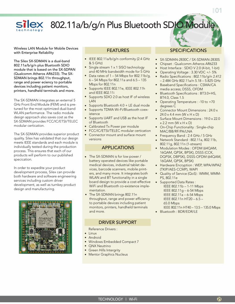
802.11a/b/g/n Plus Bluetooth SDIO Module
Wireless LAN Module for Mobile Devices with Enterprise Reliability
The Silex SX-SDMAN is a dual-band 802.11a/b/g/n plus Bluetooth SDIO module that is based on the SX-SDPAN (Qualcomm Atheros AR6233). The SX-SDMAN brings 802.11n throughput, range and power eciency to portable devices including patient monitors, printers, handheld terminals and more.
The SX-SDMAN integrates an external 5 GHz Front End Module (FEM) and is pre-tuned for the most optimized dual-band WLAN performance. The radio module design approach also saves cost as the SX-SDMAN provides FCC/IC/ETSI/TELEC modular certication.
The SX-SDMAN provides superior product quality. Silex has validated that our design meets IEEE standards and each module is individually tested during the production process. This ensures that each of our products will perform to our published specication.
In order to expedite your product development process, Silex can provide both hardware and software engineering services including custom driver development, as well as turnkey product design and manufacturing.
IEEE 802.11a/b/g/n conformity (2.4 GHz & 5 GHz) Single stream 1 x 1 SISO technology and 40 MHz bandwidth mode for 5 GHz Data rates of 1 – 54 Mbps for 802.11b/g, 6 – 54 Mbps for 802.11a and 6.5 – 135 Mbps for 802.11n Supports IEEE 802.11e, IEEE 802.11h and IEEE 802.11iSupports SDIO 2.0 as host IF of wireless LANSupports Bluetooth 4.0 + LE dual modeSupports TDMA Wi-Fi/Bluetooth coex-istenceSupports UART and USB as the host IF of Bluetooth Calibrated Tx Power per module FCC/IC/ETSI/TELEC modular certication Connector mount and surface mount versions
FEATURES
APPLICATIONS
•
•
•
•
•
••
•
••
•
The SX-SDMAN is for low power / battery operated devices like portable medical devices, industrial tablet de-vices, barcode scanners, mobile print-ers, and many more. It integrates both WLAN and BT functionality in a single board design to provide a cost-effective WiFi and Bluetooth co-existence imple-mentation.The SX-SDMAN brings 802.11n throughput, range and power efficiency to portable devices including patient monitors, printers, handheld terminals and more.
•
TECHNOLOGY | Wi-Fi
•
SX-SDMAN-2830C / SX-SDMAN-2830SChipset : Qualcomm Atheros AR6233 Host Interface : SDIO V 2.0 (4-bit, 1-bit) Operating Voltage : 3.30 VDC +/- 5% Radio Specifications : 802.11b/g/n 2.412 – 2.484 GHz 802.11a/n 5.18 – 5.825 GHz Baseband Specifications : CSMA/CA media access; DSSS, OFDM Bluetooth Specifications : BT3.0+HS, BT4.0, Class 1.5Operating Temperature : -10 to +70 degrees C Connector Mount Dimensions : 24.0 x 24.0 x 4.4 mm (W x H x D) Surface Mount Dimensions : 19.0 x 22.0 x 2.2 mm (W x H x D)On-Chip Functionality : Single-chip MAC/BB/RF/PA/LNAFrequency Band : 2.4 GHz / 5 GHz Network Standard : 802.11a, 802.11b, 802.11g, 802.11n (1-stream) Modulation Modes : OFDM (64QAM, 16QAM, QPSK, BPSK), DSSS (CCK, DQPSK, DBPSK), DSSS-OFDM (64QAM, 16QAM, QPSK, BPSK) Hardware Encryption : WEP, WPA/WPA2 (TKIP/AES-CCMP), WAPI Quality of Service (QoS) : WMM, WMM-PS, 802.11e Supported Data Rates : IEEE 802.11b – 1-11 Mbps IEEE 802.11g – 6-54 Mbps IEEE 802.11a – 6-54 Mbps IEEE 802.11n HT20 – 6.5 – 65.0 Mbps IEEE 802.11n HT40 – 13.5 – 135.0 MbpsBluetooth : BDR/EDR/LE
•••••
•
•
•
•
•
SPECIFICATIONS
•
••
•
•
•
•
•
Reference Drivers :LinuxAndroidWindows Embedded Compact 7QNX NeutrinoGreen Hills IntergrityMentor Graphics Nucleus
••••••
DRIVER SUPPORT
21
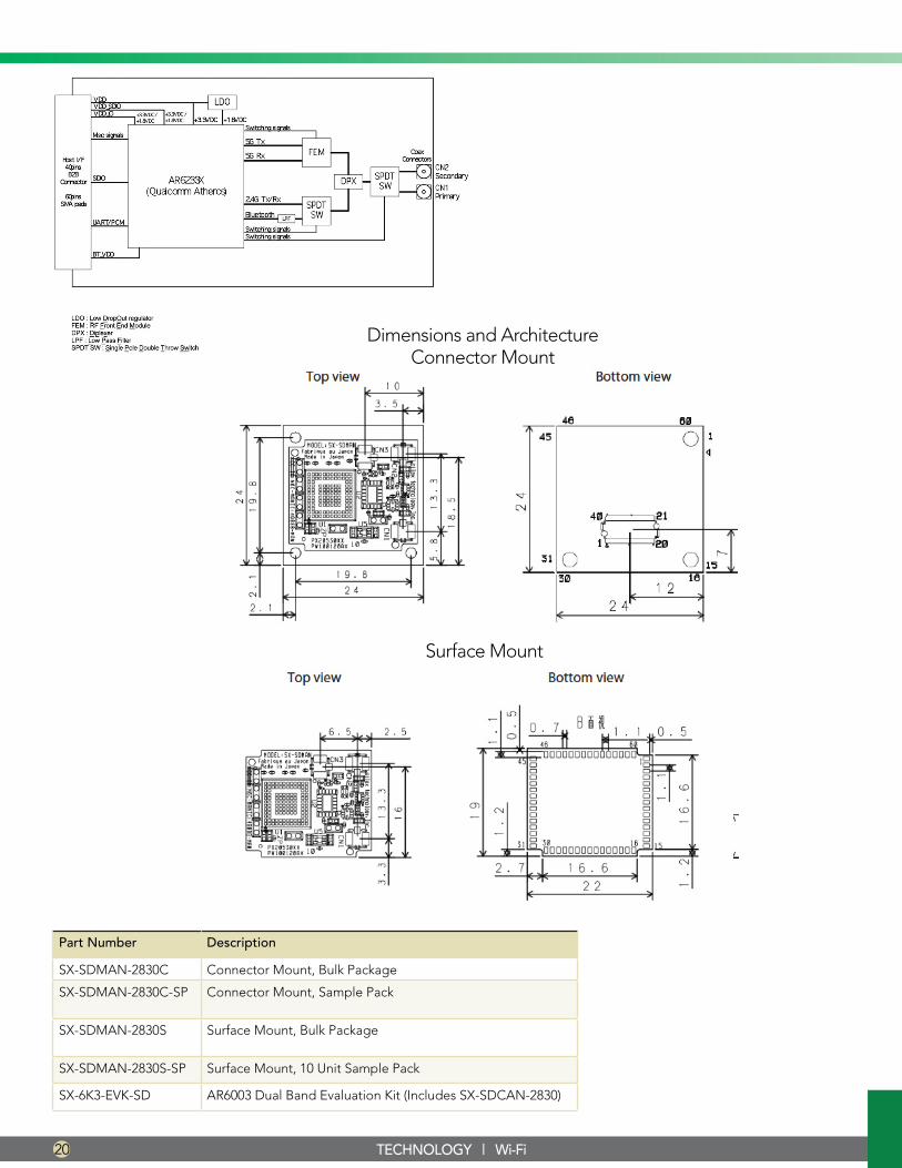
Dimensions and ArchitectureConnector Mount
Surface Mount
TECHNOLOGY | Wi-Fi
Part Number Description
SX-SDMAN-2830C Connector Mount, Bulk Package
SX-SDMAN-2830C-SP Connector Mount, Sample Pack
SX-SDMAN-2830S Surface Mount, Bulk Package
SX-SDMAN-2830S-SP Surface Mount, 10 Unit Sample Pack
SX-6K3-EVK-SD AR6003 Dual Band Evaluation Kit (Includes SX-SDCAN-2830)
20

ISSU
E 01
www.FutureElectronics.com