Gesamtkatalog
36
Steigstrangprofile Heizkörperanbindesysteme Main Catalogue 2003 / 2004
-
Upload
eduard-riemschneider -
Category
Documents
-
view
217 -
download
2
description
HZ Gesamtkatalog Englisch
Transcript of Gesamtkatalog
Stei
gstr
angp
rofil
eH
eizk
örpe
ranb
inde
syst
eme
Main Catalogue
2003 / 2004

Stei
gstr
angp
rofil
eH
eizk
örpe
ranb
inde
syst
eme
2
Table of Contents
Stei
gstr
angp
rofi l
eH
eizk
örpe
ranb
inde
syst
eme
3
Skirting Board Profi lesThe HZ System for Pre-Wall Installation 6
The different types of brackets 7
SLF 2000 – The universal profi le for pipes up to 22 mm 8 / 9
SLT 2000 – The profi le with self-adhesive tape for use with carpets,
for pipes up to 22 mm 10 / 11
SLL 2000 – The profi le for use with a cable duct or a 3rd pipe up to 22 mm 12 / 13
SLF 28-2000 – The profi le for pipes up to 28 mm and when more space is needed 14
SLHW – Skirting board of wood-based material
in natural, or in light oak or abachi veneers 15
Range of corner moulded parts / Methods of installation 16 / 17
BLF – Dummy skirting board profi les made of plastic hollow space profi le 18
BLT / BL – Carpet dummy skirting board and dummy skirting board
made of solid wood 19
Accessories for Skirting Boards 20
Please observe our guidelines for installation
Table of Contents
Radiator Connection SystemsHKU - The easy and complete way to connect radiators 21
HKU - Radiator connections for soldering 22 / 23
HKU - Radiator connections for press-fi tting 24 / 25
HKU - Radiator connections with tapered seal / female thread / for push-fi tting 26 / 27
AWA / PBV – 90° elbows with shut off valve / 90° bends 28 / 29
Riser SectionsSTK - Riser unions 30
STP U - Riser section, plastic, U-shaped 31
STP U - Riser section, plastic, L-shaped 32
Accessories for Riser Systems 33
Request for Promotional Material 34
Company Portrait 35 Ris
er S
ectio
nsRa
diat
or C
onne
ctio
n Sy
stem
sSk
irtin
g B
oard
Pro
fi les

Stei
gstr
angp
rofil
eH
eizk
örpe
ranb
inde
syst
eme
4

Stei
gstr
angp
rofil
eH
eizk
örpe
ranb
inde
syst
eme
5
1
23
1 HZ Skirting boards for concealing heating pipes and electrical wiring.
2 HZ Riser sections for concealing pipes on walls and ceilings.
3 HZ Radiator connections for quick connection of radiators with pre-wall installation.
Ris
er S
ectio
nsRa
diat
or C
onne
ctio
n Sy
stem
sSk
irtin
g B
oard
Pro
files

6
The HZ System for Pre-Wall Installation
The advantages of pre-wall installation when modernising heating systems are obvious: no need to chisel out chasing, no rubble in rooms which are occupied, no extra renovation work, quick installation times, savings in expense.
State-of-the-art pre-wall installation consists of cladding heating pipes that are laid on top of plaster. HZ supplies the right system for cladding pipes.
Heating pipes parallel to the floor are concealed with the high-quality HZ skirting board profiles. A wide range of décors and different sized skirting boards will meet practically any conceivable requirement. HZ’s simple fixing methods ensure quick and easy installation.
For vertical piping HZ supplies riser sections in U and L shapes in a total of seven different sizes. Pipes along walls and ceilings can be concealed without any difficulty. They are indispensable for cladding insulated risers.
Fast and attractive fitting of radiators can be achieved using the HZ radiator connection systems for pre-wall installation. They are available for all types of connections: soldering - press-fitting - screwing - push-fitting. Use these and you will save considerable time in pre-wall installation.
Particular importance is attached to easy installation for HZ products. Even with difficult installation situations in older buildings, fast and problem-free mounting is possible.
7
Brackets The different types of brackets
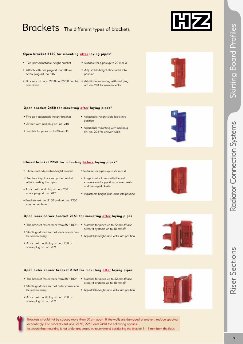
Open bracket 2150 for mounting after laying pipes*
• Two-part adjustable-height bracket
• Attach with nail plug art. no. 208 or screw plug art. no. 209
• Brackets art. nos. 2150 and 2250 can be combined
• Suitable for pipes up to 22 mm Ø
• Adjustable-height slide locks into position
• Additional mounting with nail plug art. no. 204 for uneven walls
Open bracket 2450 for mounting after laying pipes*
• Two-part adjustable-height bracket
• Attach with nail plug art. no. 210
• Suitable for pipes up to 28 mm Ø
• Adjustable-height slide locks into position
• Additional mounting with nail plug art. no. 204 for uneven walls
Open inner corner bracket 2151 for mounting after laying pipes
• The bracket fi ts corners from 85 °-100 °
• Stable guidance so that inner corner can be slid on easily
• Attach with nail plug art. no. 208 or screw plug art. no. 209
• Suitable for pipes up to 22 mm Ø and press-fi t systems up to 18 mm Ø
• Adjustable-height slide locks into position
Open outer corner bracket 2152 for mounting after laying pipes
• The bracket fi ts corners from 85 °-100 °
• Stable guidance so that outer corner can be slid on easily
• Attach with nail plug art. no. 208 or screw plug art. no. 209
• Suitable for pipes up to 22 mm Ø and press-fi t systems up to 18 mm Ø
• Adjustable-height slide locks into position
Brackets should not be spaced more than 50 cm apart. If the walls are damaged or uneven, reduce spacing accordingly. For brackets Art.nos. 2150, 2250 and 2450 the following applies: to ensure that mounting is not under any strain, we recommend positioning the bracket 1 – 3 mm from the fl oor.
Closed bracket 2250 for mounting before laying pipes*
• Three-part adjustable-height bracket
• Use the clasp to close up the bracket after inserting the pipes
• Attach with nail plug art. no. 208 or screw plug art. no. 209
• Brackets art. no. 2150 and art. no. 2250 can be combined
• Suitable for pipes up to 22 mm Ø
• Large contact area with the wall ensures solid support on uneven walls and damaged plaster • Adjustable-height slide locks into position
Ris
er S
ectio
nsRa
diat
or C
onne
ctio
n Sy
stem
sSk
irtin
g B
oard
Pro
fi les
8
Ø 22
1735
3472
80 95
39
+17
-7
0 ~2
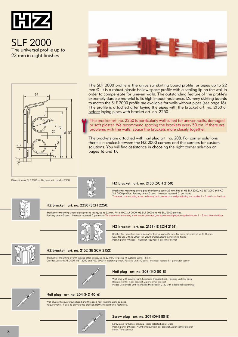
SLF 2000The universal profi le up to 22 mm in eight fi nishes
HZ bracket art. no. 2250 (SCH 2250)
Bracket for mounting under pipes prior to laying, up to 22 mm. Fits all HZ SLF 2000, HZ SLT 2000 and HZ SLL 2000 profi les.Packing unit: 40 pces Number required: 2 per metre To ensure that mounting is not under any strain, we recommend positioning the bracket 1 – 3 mm from the fl oor.
HZ bracket art. no. 2151 (IE SCH 2151)
Bracket for mounting over pipes after laying, up to 22 mm, for press-fi t systems up to 18 mm.Only for use with IE 2000, IET 2000 and IEL 2000 in matching fi nish.Packing unit: 40 pces Number required: 1 per inner corner
HZ bracket art. no. 2152 (IE SCH 2152)
Bracket for mounting over the pipes after laying, up to 22 mm, for press-fi t systems up to 18 mm.Only for use with AE 2000, AET 2000 and AEL 2000 in matching fi nish. Packing unit: 40 pces Number required: 1 per outer corner
Nail plug art. no. 204 (ND 40-6)
Wall plug with countersunk head and threaded nail. Packing unit: 50 pcesRequirements: 1 pce. to provide the bracket 2150 with additional fastening.
Dimensions of SLF 2000 profi le, here with bracket 2150HZ bracket art. no. 2150 (SCH 2150)
Bracket for mounting over pipes after laying, up to 22 mm. Fits all HZ SLF 2000, HZ SLT 2000 and HZ SLL 2000 profi les. Packing unit: 40 pces Number required: 2 per metreTo ensure that mounting is not under any strain, we recommend positioning the bracket 1 – 3 mm from the fl oor.
Nail plug art. no. 208 (ND 80-8)
Wall plug with countersunk head and threaded nail. Packing unit: 50 pcesRequirements: 1 per bracket, 2 per corner bracketPlease use article 204 to provide the bracket 2150 with additional fastening!
The SLF 2000 profi le is the universal skirting board profi le for pipes up to 22 mm Ø. It is a robust plastic hollow space profi le with a sealing lip on the wall in order to compensate for uneven walls. The outstanding feature of the profi le‘s extremely durable material is its high impact resistance. Dummy skirting boards to match the SLF 2000 profi le are available for walls without pipes (see page 18). The profi le is attached after laying the pipes with the bracket art. no. 2150 or before laying pipes with bracket art. no. 2250.
The bracket art. no. 2250 is particularly well suited for uneven walls, damaged or soft plaster. We recommend spacing the brackets every 50 cm. If there are problems with the walls, space the brackets more closely together.
The brackets are attached with nail plug art. no. 208. For corner solutions there is a choice between the HZ 2000 corners and the corners for custom solutions. You will fi nd assistance in choosing the right corner solution on pages 16 and 17.
Screw plug art. no. 209 (DHB 80-8)
Screw plug for hollow block & Rigips (plasterboard) wallsPacking unit: 50 pces Number required:1 per bracket, 2 per corner bracketNote: Torx contour

9
Butt joint
Packing unit: 10 pcesSame article also for BLF, see page 18
MapleArt. no. 2013(ST A)
Light beechArt. no. 2023(ST BH)
Dark beechArt. no. 4133(ST BD)
White ashArt. no. 4143(ST EW)
Light oakArt. no. 163(ST EH)
Dark oakArt. no. 173(ST ED)
WhiteArt. no. 183(ST W)
GreyArt. no. 193(ST G)
Left end piece
Packing unit: 10 pcesSame article also for BLF, see page 18
MapleArt. no. 2014(ES A left)
Light beechArt. no. 2024(ES BH left)
Dark beechArt. no. 4134(ES BD left)
White ashArt. no. 4144(ES EW left)
Light oakArt. no. 164(ES EH left)
Dark oakArt. no. 174(ES ED left)
WhiteArt. no. 184(ES W left)
GreyArt. no. 194(ES G left)
Right end piece
Packing unit: 10 pcesSame article also for BLF, see page 18
MapleArt. no. 2015(ES A right)
Light beechArt. no. 2025(ES BH right)
Dark beechArt. no. 4135(ES BD right)
White ashArt. no. 4145(ES EW right)
Light oakArt. no. 165(ES EH right)
Dark oakArt. no. 175(ES ED right)
WhiteArt. no. 185(ES W right)
GreyArt. no. 195(ES G right)
Inner corner for custom solutionsFor working without inner corner brackets, (also for BLF or transition piece from BLF to SLF) Packing unit: 10 pces
MapleArt. no. 2016(IE A)
Light beechArt. no. 2026(IE BH)
Dark beechArt. no. 4131(IE BD)
White ashArt. no. 4141(IE EW)
Light oakArt. no. 161(IE EH)
Dark oakArt. no. 171(IE ED)
WhiteArt. no. 181(IE W)
GreyArt. no. 191(IE G)
Outer corner for custom solutionsFor working without outer corner brackets, (also for BLF or transition piece from BLF to SLF) Packing unit: 10 pces
MapleArt. no. 2017(AE A)
Light beechArt. no. 2027(AE BH)
Dark beechArt. no. 4132(AE BD)
White ashArt. no. 4142(AE EW)
Light oakArt. no. 162(AE EH)
Dark oakArt. no. 172(AE ED)
WhiteArt. no. 182(AE W)
GreyArt. no. 192(AE G)
Outside corner
IMPORTANT:Only for use in combination with AE SCH 2152 Packing unit: 10 pces
MapleArt. no. 2012(AE 2000 A)
Light beechArt. no. 2022(AE 2000 BH)
Dark beechArt. no. 2032(AE 2000 BD)
White ashArt. no. 2042(AE 2000 EW)
Light oakArt. no. 2062(AE 2000 EH)
Dark oakArt. no. 2072(AE 2000 ED)
WhiteArt. no. 2082(AE 2000 W)
GreyArt. no. 2092(AE 2000 G)
Inside corner
IMPORTANT:Only for use in combination with IE SCH 2151 Packing unit: 10 pces
MapleArt. no. 2011(IE 2000 A)
Light beechArt. no. 2021(IE 2000 BH)
Dark beechArt. no. 2031(IE 2000 BD)
White ashArt. no. 2041(IE 2000 EW)
Light oakArt. no. 2061(IE 2000 EH)
Dark oakArt. no. 2071(IE 2000 ED)
WhiteArt. no. 2081(IE 2000 W)
GreyArt. no. 2091(IE 2000 G)
SLF 2000 profi le
Skirting board made of plastic hollow space profi le Packing unit: 40 mLength: 4 m
MapleArt. no. 2010(SLF 2000 A)
Light beechArt. no. 2020(SLF 2000 BH)
Dark beechArt. no. 2030(SLF 2000 BD)
White ashArt. no. 2040(SLF 2000 EW)
Light oakArt. no. 2060(SLF 2000 EH)
Dark oakArt. no. 2070(SLF 2000 ED)
WhiteArt. no. 2080(SLF 2000 W)
GreyArt. no. 2090(SLF 2000 G)
Maple2010
Light beech2020
Dark beech2030
White ash2040
Light oak2060
Dark oak2070
White (≈RAL 9010)2080
Grey (≈RAL 7035)2090
When using the HZ 2000 inner corner you need an inner corner bracket (art. no. 2151), when using the HZ 2000 outer corner an outer corner bracket is needed (art. no. 2152). When cutting the skirting board profi le to size, remember that for each inner corner bracket used the profi le has to be shortened by 45 mm.
The corner brackets provide solid support for the profi le and the corner moulded parts and no mitre cut is needed. This saves valuable time in installation. The profi le is pressed against the wall and pushed down into the brackets. The inner and outer corners are slid over the square-cut skirting boards onto the corner brackets.
With the SLF 2000 profi le you can choose from eight fi nishes and matching moulded parts.
Together with the HZ radiator connections you can achieve a technically sophisticated solution and an attractive appearance.
With very uneven walls and fl oors we recommend using an additional sealing lip which can be stuck on (see page 20).
Ris
er S
ectio
nsRa
diat
or C
onne
ctio
n Sy
stem
sSk
irtin
g B
oard
Pro
fi les
10
-5
0
+19
46
7
4079 96
3523
Ø 22
~2
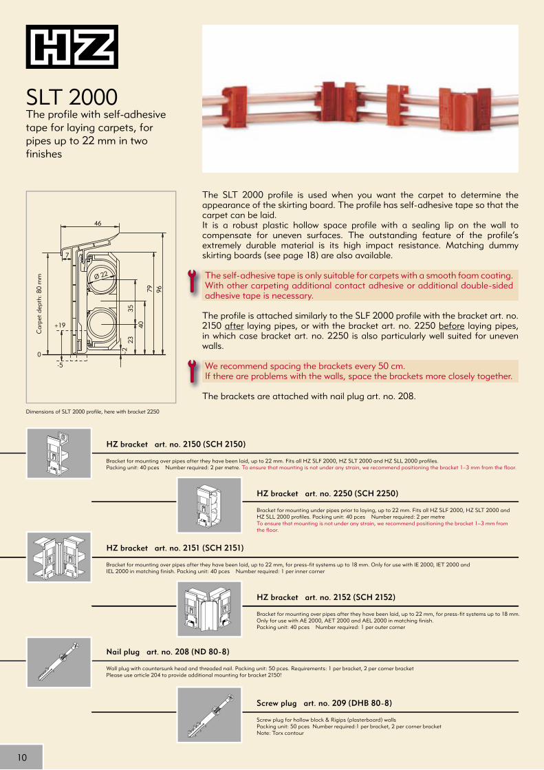
SLT 2000The profi le with self-adhesive tape for laying carpets, for pipes up to 22 mm in two fi nishes
Dimensions of SLT 2000 profile, here with bracket 2250
HZ bracket art. no. 2150 (SCH 2150)
Bracket for mounting over pipes after they have been laid, up to 22 mm. Fits all HZ SLF 2000, HZ SLT 2000 and HZ SLL 2000 profi les.Packing unit: 40 pces Number required: 2 per metre. To ensure that mounting is not under any strain, we recommend positioning the bracket 1–3 mm from the fl oor.
HZ bracket art. no. 2250 (SCH 2250)
Bracket for mounting under pipes prior to laying, up to 22 mm. Fits all HZ SLF 2000, HZ SLT 2000 and HZ SLL 2000 profi les. Packing unit: 40 pces Number required: 2 per metreTo ensure that mounting is not under any strain, we recommend positioning the bracket 1–3 mm from the fl oor.
HZ bracket art. no. 2151 (SCH 2151)
Bracket for mounting over pipes after they have been laid, up to 22 mm, for press-fi t systems up to 18 mm. Only for use with IE 2000, IET 2000 and IEL 2000 in matching fi nish. Packing unit: 40 pces Number required: 1 per inner corner
HZ bracket art. no. 2152 (SCH 2152)
Bracket for mounting over pipes after they have been laid, up to 22 mm, for press-fi t systems up to 18 mm.Only for use with AE 2000, AET 2000 and AEL 2000 in matching fi nish.Packing unit: 40 pces Number required: 1 per outer corner
Nail plug art. no. 208 (ND 80-8)
Wall plug with countersunk head and threaded nail. Packing unit: 50 pces. Requirements: 1 per bracket, 2 per corner bracketPlease use article 204 to provide additional mounting for bracket 2150!
Screw plug art. no. 209 (DHB 80-8)
Screw plug for hollow block & Rigips (plasterboard) wallsPacking unit: 50 pces Number required:1 per bracket, 2 per corner bracketNote: Torx contour
The SLT 2000 profi le is used when you want the carpet to determine the appearance of the skirting board. The profi le has self-adhesive tape so that the carpet can be laid.It is a robust plastic hollow space profi le with a sealing lip on the wall to compensate for uneven surfaces. The outstanding feature of the profi le’s extremely durable material is its high impact resistance. Matching dummy skirting boards (see page 18) are also available.
The self-adhesive tape is only suitable for carpets with a smooth foam coating. With other carpeting additional contact adhesive or additional double-sided adhesive tape is necessary.
The profi le is attached similarly to the SLF 2000 profi le with the bracket art. no. 2150 after laying pipes, or with the bracket art. no. 2250 before laying pipes, in which case bracket art. no. 2250 is also particularly well suited for uneven walls.
We recommend spacing the brackets every 50 cm.If there are problems with the walls, space the brackets more closely together.
The brackets are attached with nail plug art. no. 208.
Car
pet
dept
h: 8
0 m
m
11
Butt joint
Packing unit: 10 pces
Light oakArt. no. 263(STT EH)
WhiteArt. no. 283(STT W)
Left end piece
Packing unit: 10 pces
Light oakArt. no. 264(EST EH left)
WhiteArt. no. 284(EST W left)
Right end piece
Packing unit: 10 pces
Light oakArt. no. 265(EST EH right)
WhiteArt. no. 285(EST W right)
Inner corner for custom solutionsFor working without inner corner brackets, Packing unit: 10
Light oakArt. no. 261(IET EH)
WhiteArt. no. 281(IET W)
Outer corner for custom solutionsFor working without outer corner brackets, Packing unit: 10
Light oakArt. no. 262(AET EH)
WhiteArt. no. 282(AET W)
Outer corner
IMPORTANT:Only for use in combination with AE SCH 2152 Packing unit: 10 pces
Light oakArt. no. 2262(AET 2000 EH)
WhiteArt. no. 2282(AET 2000 W)
Inner corner
IMPORTANT:Only for use in combination with IE SCH 2151Packing unit: 10 pces
Light oakArt. no. 2261(IET 2000 EH)
WhiteArt. no. 2281(IET 2000 W)
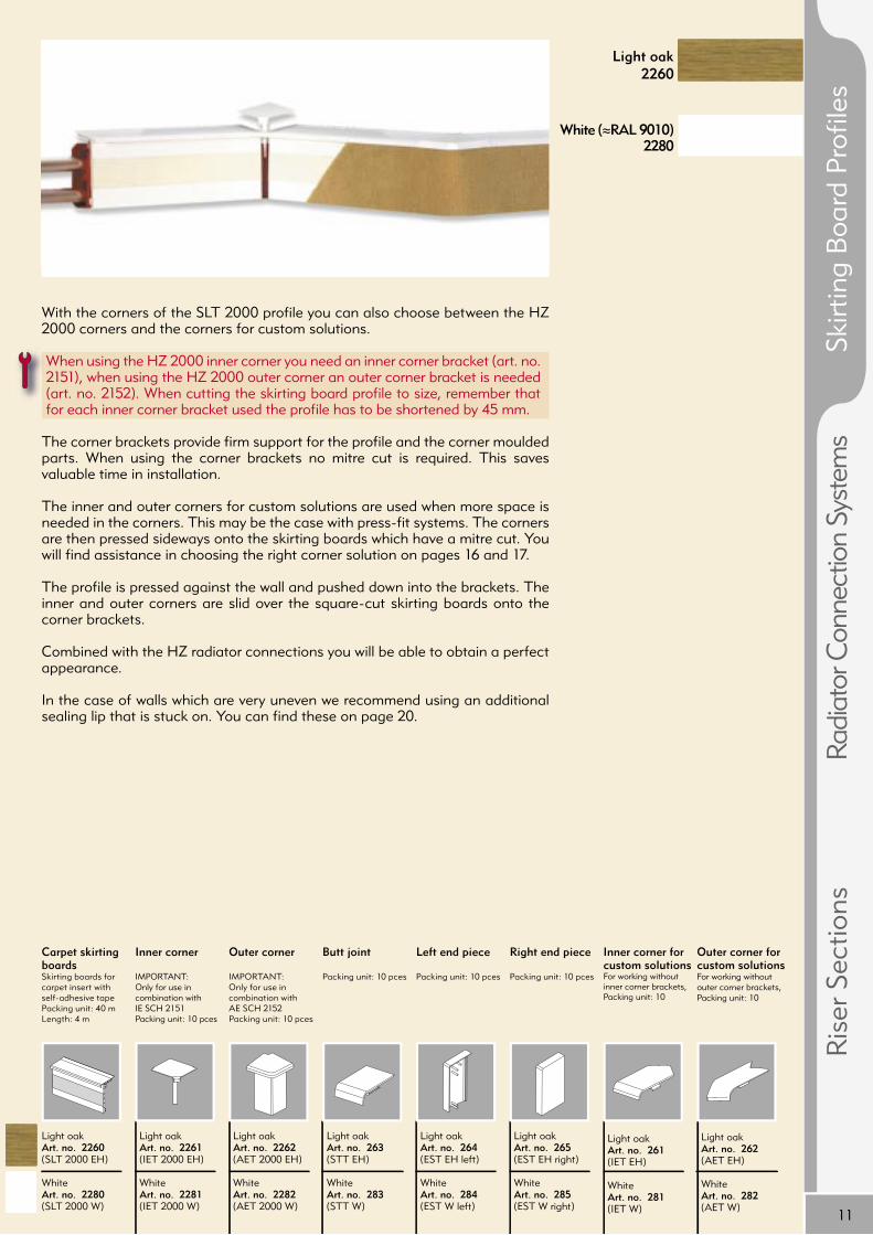
Carpet skirting boardsSkirting boards for carpet insert with self-adhesive tapePacking unit: 40 mLength: 4 m
Light oakArt. no. 2260(SLT 2000 EH)
WhiteArt. no. 2280(SLT 2000 W)
Light oak2260
White (≈RAL 9010)2280
With the corners of the SLT 2000 profi le you can also choose between the HZ 2000 corners and the corners for custom solutions.
When using the HZ 2000 inner corner you need an inner corner bracket (art. no. 2151), when using the HZ 2000 outer corner an outer corner bracket is needed (art. no. 2152). When cutting the skirting board profi le to size, remember that for each inner corner bracket used the profi le has to be shortened by 45 mm.
The corner brackets provide fi rm support for the profi le and the corner moulded parts. When using the corner brackets no mitre cut is required. This saves valuable time in installation.
The inner and outer corners for custom solutions are used when more space is needed in the corners. This may be the case with press-fi t systems. The corners are then pressed sideways onto the skirting boards which have a mitre cut. You will fi nd assistance in choosing the right corner solution on pages 16 and 17.
The profi le is pressed against the wall and pushed down into the brackets. The inner and outer corners are slid over the square-cut skirting boards onto the corner brackets.
Combined with the HZ radiator connections you will be able to obtain a perfect appearance.
In the case of walls which are very uneven we recommend using an additional sealing lip that is stuck on. You can fi nd these on page 20.
Ris
er S
ectio
nsRa
diat
or C
onne
ctio
n Sy
stem
sSk
irtin
g B
oard
Pro
fi les

12
35
(+20)
Ø 22
0
39
30
51
6810
7
127
SLL 2000SLL 2000 – The profi le for inserting a cable duct or a 3rd pipe up to 22 mm, in three fi nishes
Dimensions of the SLL 2000 profile, here with bracket 2250 and commercial cable duct e.g. Tehalit 30 x 30 mm
HZ bracket art. no. 2150 (SCH 2150)
Bracket for mounting over pipes after laying, up to 22 mm. Fits all HZ SLF 2000, HZ SLT 2000 and HZ SLL 2000 profi les.Packing unit: 40 pces Number required: 2 per metre.
HZ bracket art. no. 2250 (SCH 2250)
Bracket for mounting under pipes prior to laying, up to 22 mm. Fits all HZ SLF 2000, HZ SLT 2000 and HZ SLL 2000 profi les. Packing unit: 40 pces Number required: 2 per metre.
HZ bracket art. no. 2151 (IE SCH 2151)
Bracket for mounting over the pipes after laying them, up to 22 mm, for press-fit systems up to 18 mm. Only for use with IE 2000, IET 2000 and IEL 2000 in matching finish. Packing unit: 40 pces Number required: 1 per inner corner
HZ bracket art. no. 2152 (IE SCH 2152)
Bracket for mounting over the pipes after laying them, up to 22 mm, for press-fit systems up to 18 mm. Only for use with AE 2000, AET 2000 and AEL 2000 in matching finish Packing unit: 40 pces Number required: 1 per outer corner
Nail plug art. no. 208 (ND 80-8)
Wall plug with countersunk head and threaded nail. Packing unit: 50 pcesRequirements: 1 per bracket, 2 per corner bracket Please use article 204 to provide additional mounting for bracket 2150!
Screw plug art. no. 209 (DHB 80-8)
Screw plug for hollow block & Rigips (plasterboard) wallsPacking unit: 50 pces Number required:1 per bracket, 2 per corner bracketNote: Torx contour
The SLL 2000 profi le is used when a cable duct is also laid (recommended 30 x 30 mm) or when laying a 3rd pipe. It is a robust plastic hollow space profi le with a sealing lip on the wall in order to compensate for uneven walls. When used in conjunction with the socket container it is the ideal profi le for quick and inexpensive modernisation of your home. It is mounted after laying the pipes with the bracket art. no. 2150 or before laying them with bracket art. no. 2250.
We recommend spacing the brackets every 50 cm. If there are problems with the walls, space the brackets more closely together. When cutting the skirting board profi le to size, remember that for each inner corner bracket used the profi le has to be shortened by 45 mm. If a cable duct is also laid, the bracket is mounted above the cable duct and the slide can be slid on as far as the cable duct. With bracket art. no. 2150 care must be taken that a minimum spacing of at least 6 mm is kept to and that it is not mounted on top of the cable duct.When laying a third pipe the bracket is positioned between the two top pipes. The bracket art. no. 2150 should also be mounted between the two lower pipes without a slide, in order to give the 3rd pipe solid support.
There is a choice for corner solutions between the HZ 2000 corners and the corners for custom solutions. You will fi nd assistance in choosing the right corner solution on pages 16 and 17.

13
a
222
a
68+
3
Ø 22
90
a52
Butt joint
Packing unit: 10 pces
Light oakArt. no. 363(STL EH)
WhiteArt. no. 383(STL W)
GreyArt. no. 393(STL G)
Left end piece
Packing unit: 10 pces
Light oakArt. no. 364(ESL EH left)
WhiteArt. no. 384(ESL W left)
GreyArt. no. 394(ESL G left)
Right end piece
Packing unit: 10 pces
Light oakArt. no. 365(ESL EH right)
WhiteArt. no. 385(ESL W right)
GreyArt. no. 395(ESL G right)
Inner corner for custom solutionsFor working without inner corner brackets Packing unit: 10 pces
Light oakArt. no. 361(IEL EH)
WhiteArt. no. 381(IEL W)
GreyArt. no. 391(IEL G)
Outer corner for custom solutionsFor working without outer corner brackets Packing unit: 10 pces
Light oakArt. no. 362(AEL EH)
WhiteArt. no. 382(AEL W)
GreyArt. no. 392(AEL G)
Outer corner
IMPORTANT:Only use in combination with AE SCH 2152Packing unit: 10 pces
Light oakArt. no. 2362(AEL 2000 EH)
WhiteArt. no. 2382(AEL 2000 W)
GreyArt. no. 2392(AEL 2000 G)
Light oak2360
White (≈RAL 9010)
2380
The profile is pressed against the wall and pushed down into the brackets. The inner and outer corners are slid over the square-cut skirting boards onto the corner brackets. With the SLL 2000 profile you can choose from three finishes and matching moulded parts.
The SLL profile is suitable for HZ radiator connections.
The socket container matching the SLL profile is suitable for sockets, TV aerial and telephone outlets as well as outlets for data transmission. The socket containers in white plastic are available in two different designs.The container, consisting of rear and front pieces, is easy to install.The socket container art. no. 331 is designed for sockets with a central disc and without frame (recess opening 62 x 62 mm, make GIRA, SCHUKO socket 16/250, art. no. 188XX), the socket container art. no. 332 is designed for commercial electrical outlets and Schuko earthed sockets with a full plate (recess opening 73 x 73 mm).
The sockets themselves are not included in the scope of supply!
Grey(≈RAL 7035)
2390
HZ socket container art. no. 331 (SDC 62x62)
Socket container: plastic, white, similar to RAL 9010, recess opening 62x62 mm, suitable for sockets, TV aerial and telephone outlets, outlets for data transmission, not included in the scope of supply, container consists of front and rear pieces for simple mounting.Only suitable for Gira sockets (S-Color)
HZ socket container art. no. 332 (SDC 73x73)
Socket container: plastic, white, similar to RAL 9010, recess opening 73x73 mm, suitable for sockets, TV aerial and telephone outlets, outlets for data transmission, not included in the scope of supply, container consists of front and rear pieces for simple mounting.
Inner corner
IMPORTANT:Only use in combination with IE SCH 2151Packing unit: 10 pces
Light oakArt. no. 2361(IEL 2000 EH)
WhiteArt. no. 2381(IEL 2000 W)
GreyArt. no. 2391(IEL 2000 G)
The test report from the informative inspectionby the VDE institute dated 21.06.96, ref. 19692-8100-4001-A3D, is available fromHans Weitzel GmbH & Co. KG.Please request our separate planning instructions and the guidelines for installation.
Rules for installation:1. Forward - always upper pipe2. Backflow - always lower pipe3. Cable ducts from 30 x 30 mm, use those with VDE approval symbol (e.g. Tehalit LF 30030)4. It is essential to observe the separate instructions for planning and guidelines for installation.
Refer to description of article for outlet dimensions
SLL 2000 profile
Skirting boards made of plastic hollow space profile for cable duct or 3rd pipe Packing unit: 40 mLength: 4 m
Light oakArt. no. 2360(SLL 2000 EH)
WhiteArt. no. 2380SLL 2000 W)
GreyArt. no. 2390(SLL 2000 G)
Ris
er S
ectio
nsRa
diat
or C
onne
ctio
n Sy
stem
sSk
irtin
g B
oard
Pro
files

14
2040
4083
9211
0
Ø 28
+17
-7
0
45
~2
SLF 28-2000 The profi le for pipes up to 28 mm and when more space is needed, in two fi nishes
Butt joint
Packing unit: 10 pces
Light oakArt. no. 5163(ST 28 EH)
WhiteArt. no. 5183(ST 28 W)
Left end piece
Packing unit: 10 pces
Light oakArt. no. 5164(ES 28 EH left)
WhiteArt. no. 5184(ES 28 W left)
Right end piece
Packing unit: 10 pces
Light oakArt. no. 5165(ES 28 EH right)
WhiteArt. no. 5185(ES 28 W right)
Outer corner
Packing unit: 10 pces
Light oakArt. no. 5162(AE 28 EH)
WhiteArt. no. 5182(AE 28 W)
Inside corner
Packing unit: 10 pces
Light oakArt. no. 5161(IE 28 EH)
WhiteArt. no. 5181(IE 28 W)
SLF 28 -2000 profileSkirting board for pipes up to 28 mm, plastic hollow space profile. Packing unit: 40 mLength: 4 m
Light oakArt. no. 2460(SLF 28-2000 EH)
WhiteArt. no. 2480(SLF 28-2000 W)
Bracket for mounting over pipes once they have been laid, up to 28 mm. Fits all HZ SLF 28-2000 profiles. Packing unit: 40 pces Number required: 2 per metre.To ensure that mounting is not under any strain, we recommend positioning the bracket 1–3 mm from the floor.
Nail plug art. no. 210 (ND 100-8)
Wall plug with countersunk head and threaded nail. Packing unit: 50 pces Requirements: 1 per bracket SCH 2450 The nail wall plug is also suitable for soft surfaces for all other HZ 2000 brackets.
Nail plug art. no. 204 (ND 40-6)
Wall plug with countersunk head and threaded nail. Packing unit: 50 pcesRequirements: 1 pce. for additional mounting of the bracket 2450.
White (≈RAL 9010)
Light oak
The SLF 28-2000 profi le is a robust plastic hollow space profi le with a sealing lip on the wall in order to compensate for uneven walls. It is used for example with pipes up to 28 mm, with press fi ttings up to 22 mm and with the HZ insulation hose for pipes up to 22 mm. You will fi nd a detailed summary of areas of application depending on the pipes used on pages 16 and 17.Corner brackets are dispensed with in the case of the SLF 28-2000 profi le in order to ensure maximum free space in the corners.
Bracket art. no. 2450 is used for mounting, providing all the advantages of bracket art. no. 2150 with larger dimensions. The profi le and the matching moulded parts are available in light oak and white fi nishes.
We recommend spacing the brackets every 50 cm. If there are problems with the walls, space the brackets more closely together.
When walls and fl oors are very uneven we recommend using an additional sealing lip. This can be stuck on the skirting board both towards the wall and towards the fl oor. This achieves an extra 10 mm length in the profi le. The sealing lip and other accessory parts for the skirting boards can be found on page 20.
Dimensions of SLF 28 -2000 profile, with bracket 2450
HZ bracket art. no. 2450 (SCH 2450)

15
34
29
28
90
~44
~22
~44
Abachi
Light oak
Natural
The HW – skirting board from robust wood-based material is available in natural, or in light oak or abachi veneers. It is suitable for pipes up to 22 mm in diameter with fi tting for soldering and up to 18 mm diameter with press fi tting.
It is mounted with a cheese-head or spax screw.In the corners the profi le is given an exact mitre cut.
In order to obtain an accurate mitre cut we offer our mitre cutting device or precision saw (see page 20).Please note that laying HZ insulation hoses (see page 20) over the entire area under the skirting board will reduce noise emission and loss of heat.
The HW – skirting board Natural is only intended for painting (NOT for staining).
To achieve a high quality opaque paint fi nish the Caparol company recommends sanding the profi le and applying a coat of primer (Capacryl Haftprimer).Then apply an opaque coat of paint with Capacryl Seidenglanz paint (various colours) or Capalac Superweiss (similar to RAL 9010).The HW – skirting boards with a veneer are for staining, for varnishing or applying an opaque coat of paint.
The HZ radiator connection art. no. 1315 / 1318 can be used in conjunction with the HW skirting board for copper soldering DN 15 and DN 18. Remove the centre ridge using pliers!
SLHW Skirting board of wood-based material
Dimensions of the SLHW wood-based material skirting board
SLHW skirting boardSkirting board for 2 pipes for 18 mm Ø press-fit and22 mm Ø solder systemsPacking unit: 20 mLength: 4 m
NaturalArt. no. 134(SLHW can be painted)
Light oakArt. no. 136(SLHW EH can be stained)
AbachiArt. no. 138(SLHW A can be stained)
End piece
Suitable for art. nos. 134, 136 and 138Can be used on the left and the rightPacking unit: 10 pces
End pieceArt. no. 133(HW E)
Ris
er S
ectio
nsRa
diat
or C
onne
ctio
n Sy
stem
sSk
irtin
g B
oard
Pro
fi les

16
2
3
1
Which of the various methods of installation is chosen depends on the available space in each case. When more space is needed, using the above solution 2 or 3 is possible without any problems. More space is needed, for instance, when larger diameter pipes are used entailing the use of larger fittings or bending radii.
Fittings and pipes from various manufacturers were tested in conjunction with the installation of the HZ 2000 System in a 90 ° corner. The following possible solutions for mounting different pipe diameters have proven themselves (see chart on right):
Different methods of installation in corners offered by the HZ 2000 System
Use of inner and outer corner moulded parts in matching finish plus inner and outer corner brackets (with SLF 2000, SLT 2000, SLL 2000).The profile is cut to length at a right angle.
Use of inner and outer corner moulded parts for custom solutions without corner bracket (for SLF 2000, SLT 2000, SLL 2000)The profile is MITRE CUT.
Use of the SLF 28-2000 profile with matching inner and outer corner form parts without corner bracket.The profile is MITRE CUT.
Note: When mounting an inner or outer corner bracket the maximum outer diameter of the fitting and the pipe should be checked, unless the system is listed on the next page.

17
2 31
20 18
2 31
Aquatherm Aquatherm SHT 16 16 20 20* 20 20
Fränkische Alpex duo 16 16 20 20* 26 20
Geberit Mepla Quattro 20 16 20 20 26 20
Giacomini R 999 -- 18 20 20* 20 20
IBP B-press 18 -- 18 -- 22 --
IBP Cuprofit 18 -- 18 -- 22 --
JRG Sanipex MT 16 16 16 20 20 20
Mapress Mapress copper 18 -- 18 -- 22 --
Mapress c-steel 18 -- 18 -- 22 --
Oventrop Copipe 20 18 20 20* 26 20
Polytherm Polyfix MT 20 16 20 20* 26 20
Roth Roth Alu Laserpex 17 17 20* 20* 25 20
TC TECEflex 20 16 20 20* 25 20
Uponor Unipipe 20 18 20 20* 20 20
Wirsbo-Velta Rapex multi 20 16 20 20* 26 20
Woeste-Ysh. Tectite 18 -- 18 -- 22 --
Woeste-Ysh. Copper, press-fit 18 -- 18 -- 22 --
Viega Profipress 18 -- 18 -- 22 --
Viega Sanfix Fosta 16 16 20 20* 25 20
General Copper, soldering 22 -- 22 -- 28 --
Remarks:
Which corner solution fits which pipe system?
Manufacturer Name of system
The fittings and pipes from the various manufacturers have been tested in conjunction with installation of the HZ 2000 - System in 90° inner and outer corners. As of: January 2003. The table may not be complete. The details given here and in our overall documentation - including the illustrations - correspond to the information currently available to us and are, to the best of our knowledge, correct and reliable. However they do not constitute a binding guarantee of their properties. Such a guarantee can only be given for the standards of our own products. The user of these products must check, test and decide with all due care on their appropriateness for the intended use at their own risk. Our liability extends only to the extent given in our General Terms and Conditions. We reserve the right to make technical modifications. Hans Weitzel GmbH & Co. KG can as a rule only give the buyer support on technical user aspects. If you have any queries please contact us directly: +49 (0)6132- 790 890.
1. number „with fitting“ gives the max. outer pipe diameter usable for use of fittings. (system specific 90 °- angles / bends )
2. number „bent“ gives the max. pipe outer diameter which can be used with hand bending. (bending with spring, bending radius = 3 x pipe outer diameter). * = chiselling out recess on wall for outside corner (with hand bending with spring, bending radius = 3 x pipe outer diameter. (chiselling out recess is no longer necessary with bending radius < 2.5 x pipe outer diameter when using bending tool. Observe any instructions from pipe manufacturers!)
With
Fitti
ngBe
nt
With
Fitti
ngBe
nt
With
Fitti
ngBe
nt
Ris
er S
ectio
nsRa
diat
or C
onne
ctio
n Sy
stem
sSk
irtin
g B
oard
Pro
files
18
16
87
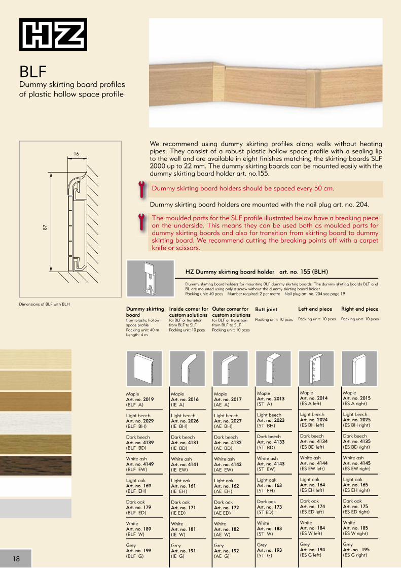
We recommend using dummy skirting profi les along walls without heating pipes. They consist of a robust plastic hollow space profi le with a sealing lip to the wall and are available in eight fi nishes matching the skirting boards SLF 2000 up to 22 mm. The dummy skirting boards can be mounted easily with the dummy skirting board holder art. no.155.
Dummy skirting board holders should be spaced every 50 cm.
Dummy skirting board holders are mounted with the nail plug art. no. 204.
The moulded parts for the SLF profi le illustrated below have a breaking piece on the underside. This means they can be used both as moulded parts for dummy skirting boards and also for transition from skirting board to dummy skirting board. We recommend cutting the breaking points off with a carpet knife or scissors.
BLF Dummy skirting board profi les of plastic hollow space profi le
Butt joint
Packing unit: 10 pces
MapleArt. no. 2013(ST A)
Light beechArt. no. 2023(ST BH)
Dark beechArt. no. 4133(ST BD)
White ashArt. no. 4143(ST EW)
Light oakArt. no. 163(ST EH)
Dark oakArt. no. 173(ST ED)
WhiteArt. no. 183(ST W)
GreyArt. no. 193(ST G)
Left end piece
Packing unit: 10 pces
MapleArt. no. 2014(ES A left)
Light beechArt. no. 2024(ES BH left)
Dark beechArt. no. 4134(ES BD left)
White ashArt. no. 4144(ES EW left)
Light oakArt. no. 164(ES EH left)
Dark oakArt. no. 174(ES ED left)
WhiteArt. no. 184(ES W left)
GreyArt. no. 194(ES G left)
Right end piece
Packing unit: 10 pces
MapleArt. no. 2015(ES A right)
Light beechArt. no. 2025(ES BH right)
Dark beechArt. no. 4135(ES BD right)
White ashArt. no. 4145(ES EW right)
Light oakArt. no. 165(ES EH right)
Dark oakArt. no. 175(ES ED right)
WhiteArt. no. 185(ES W right)
GreyArt.-no . 195(ES G right)
Outer corner for custom solutionsfor BLF or transition from BLF to SLFPacking unit: 10 pces
MapleArt. no. 2017(AE A)
Light beechArt. no. 2027(AE BH)
Dark beechArt. no. 4132(AE BD)
White ashArt. no. 4142(AE EW)
Light oakArt. no. 162(AE EH)
Dark oakArt. no. 172(AE ED)
WhiteArt. no. 182(AE W)
GreyArt. no. 192(AE G)
Inside corner for custom solutionsfor BLF or transition from BLF to SLFPacking unit: 10 pces
MapleArt. no. 2016(IE A)
Light beechArt. no. 2026(IE BH)
Dark beechArt. no. 4131(IE BD)
White ashArt. no. 4141(IE EW)
Light oakArt. no. 161(IE EH)
Dark oakArt. no. 171(IE ED)
WhiteArt. no. 181(IE W)
GreyArt. no. 191(IE G)
Dummy skirting boardfrom plastic hollow space profilePacking unit: 40 mLength: 4 m
MapleArt. no. 2019(BLF A)
Light beechArt. no. 2029(BLF BH)
Dark beechArt. no. 4139(BLF BD)
White ashArt. no. 4149(BLF EW)
Light oakArt. no. 169(BLF EH)
Dark oakArt. no. 179(BLF ED)
WhiteArt. no. 189(BLF W)
GreyArt. no. 199(BLF G)
HZ Dummy skirting board holder art. no. 155 (BLH)
Dummy skirting board holders for mounting BLF dummy skirting boards. The dummy skirting boards BLT and BL are mounted using only a screw without the dummy skirting board holder.Packing unit: 40 pces Number required: 2 per metre Nail plug art. no. 204 see page 19
Dimensions of BLF with BLH

19
15
87
7
13
85
Nail plug art. no. 204 (ND 40-6)
Wall plug with countersunk head and threaded nail. Packing unit: 50 pces Requirements: 1 per 50 cm
Wood dummy skirting boardHZ dummy skirting board in solid abachi woodPacking unit: 40 mLength: 4 m
Natural, can be stainedArt. no. 158(BL A)
Genuine oak veneerArt. no. 159(BL EH)
Carpet dummy skirting boardWith self-adhesive tape, to match SLT 2000.Packing unit: 40 mLength: 4 m(Installation without BLH)
Light oakArt. no. 269(BLT EH)
WhiteArt. no. 289(BLT W)
Dimensions of BL
BLT: The carpet dummy skirting boards are used along walls where no pipes have been laid. The carpet dummy skirting board BLT is made of a robust plastic hollow space profi le and is provided with self-adhesive tape for inserting the carpet.
The dummy skirting boards are mounted with the nail plug art. no. 204. The screw head is covered by the carpet once it is stuck down. Dummy skirting board holders are unnecessary. Precise mitre cuts are needed in the corners. No moulded parts are needed due to the shallow depth.
The profi le is available in the fi nishes light oak and white matching the SLT 2000 profi le (see pages 10 and 11).
The self-adhesive tape is only suitable for carpets with a smooth foam coating. With other carpeting extra contact adhesive or double-sided adhesive tape is necessary.
BL: Solid wood dummy skirting boards are available in two fi nishes matching the solid wood and wood-based material skirting boards (see page 15), in abachi solid wood (unfi nished, can be stained) and genuine wood veneer in light oak.
To obtain a better appearance a brass cheese head screw and wall plug should be used for mounting.
Precise mitre cuts are needed in the corners. In order to obtain an accurate mitre cut we offer our mitre cutting device or precision saw.
BLT / BL Dummy skirting board for carpets and dummy skirting board made of solid wood
Dimensions of BLT
Ris
er S
ectio
nsRa
diat
or C
onne
ctio
n Sy
stem
sSk
irtin
g B
oard
Pro
fi les
Car
pet
dept
h: 8
0 m
m
20
HZ 2000 spare slideSuitable for all HZ 2000 brackets(except SCH 2450)Packing unit: 40 pces
Art. no. 2001(S 2001)
Mitre cutting deviceSuitable for cutting all HZ profiles
Art. no. 146(GSL)
Sealing lip
Flexible, self-adhesive sealing lip for extending the skirting board along the wall and towards the floorLength: 4 m
Dark beechArt. no. 2138(DLW BD)
Light oak/light beechArt. no. 2168(DLW EH)
Dark oakArt. no. 2178(DLW ED)
White/white ashArt. no. 2188(DLW W)
GreyArt. no. 2198(DLW G)
Precision mitre sawFor perfect cutting with all HZ profiles
Art. no. 147(GS)
Cover strip
For covering the recess for the HZ radiator connection in the skirting boardPacking unit: 25 pces
MapleArt. no. 1310(AB A)
Light beechArt. no. 1320(AB BH)
Dark beechArt. no. 1330(AB BD)
Light oakArt. no. 1360(AB EH)
Dark oakArt. no. 1370(AB ED)
WhiteArt. no. 1380(AB W)
GreyArt. no. 1390(AB G)
Notching pliers
For making recesses in skirting boards for the HZ radiator connection quickly and neatly
Art. no. 9150(AKZ)
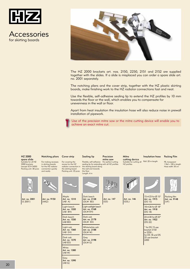
Accessories for skirting boards
Insulation hose
Roll: 20 m length
15-4-23 for Ø 15* Art. no. 1915(DS 15)
18-4-26 for Ø 18* Art. no. 1918(DS 18)
22-4-30 for Ø 22* Art. no. 1922(DS 22)
* for DS 15 usebracket 2150 or 2250 ;for DS 18 und DS 22 use bracket 2450
The HZ 2000 brackets art. nos. 2150, 2250, 2151 and 2152 are supplied together with the slides. If a slide is misplaced you can order a spare slide art. no. 2001 separately.
The notching pliers and the cover strip, together with the HZ plastic skirting boards, make fi nishing work to the HZ radiator connections fast and neat.
Use the fl exible, self-adhesive sealing lip to extend the HZ profi les by 10 mm towards the fl oor or the wall, which enables you to compensate for unevenness in the wall or fl oor.
Apart from heat insulation the insulation hose will also reduce noise in prewall installation of pipework.
Use of the precision mitre saw or the mitre cutting device will enable you to achieve an exact mitre cut.
Packing Film
PE, transparent1 Roll = 100 m lengthHose width: 50 cm
Packing filmArt. no. 9148(VF)

21
Ris
er S
ectio
nsRa
diat
or C
onne
ctio
n Sy
stem
sSk
irtin
g B
oard
Pro
fi les
The easy and completeway to connect radiators
Compression jointPage 29
90° elbow with shut-off valve and 90° bendPages 28 - 29
Radiator connectionPages 22 - 27

22
23
1/2''26
7035
dida
117
50
>15
~13
(L) (R)
35
70
~25,5
194
>15
~13
1/2''
dadi
7035
di da 59
~25,5
>15
~13
1/2"
HKU - Radiator connections for solderingRadiator connection, single-piece, for soldering art. no. 1315R/1315L/1318R/1318L
Radiator connection, two-piece, for soldering art. no. 1415/1418
Radiator connection, two-piece, for soldering art. no. 1015/1018
The upper pipe is the forward fl ow.The lower pipe is the backfl ow.When using the HZ skirting board profi les the following minimum clearances must be observed between the connection thread of the radiator and the fi nished fl oor level:When using SLF, SLT and SLHW* - at least 160 mmWhen using SLF 28-2000 - at least 180 mmWhen using SLL - at least 190 mm
*When using SLHW only the single-piece radiator connection (DN 15 and DN 18) can be used.
For braze joints we recommend Braze Tec Flussmittel Degussa h and Braze Tec Hartlot Degussa 4576.
If expansion of the pipes without stress is not possible, standard commercial expansion joints should be used.
Type Art. no. di da HKU 15 L 1015 15 18 HKU 18 L 1018 18 22
Type Art. no. di da HKU 15 1415 15 18 HKU 18 1418 18 22
Type Art. no. di da ValveHKU-E 15LR 1315R 15 18 rightHKU-E 18LR 1318R 18 22 right
HKU-E 15LL 1315L 15 18 leftHKU-E 18LL 1318L 18 22 left
IMPORTANT for all HZ radiator connections for soldering:
22
23
min. 40 -max. 100
min.120 - max.135
min. 55 - max. 145
min. 160 - max. 235
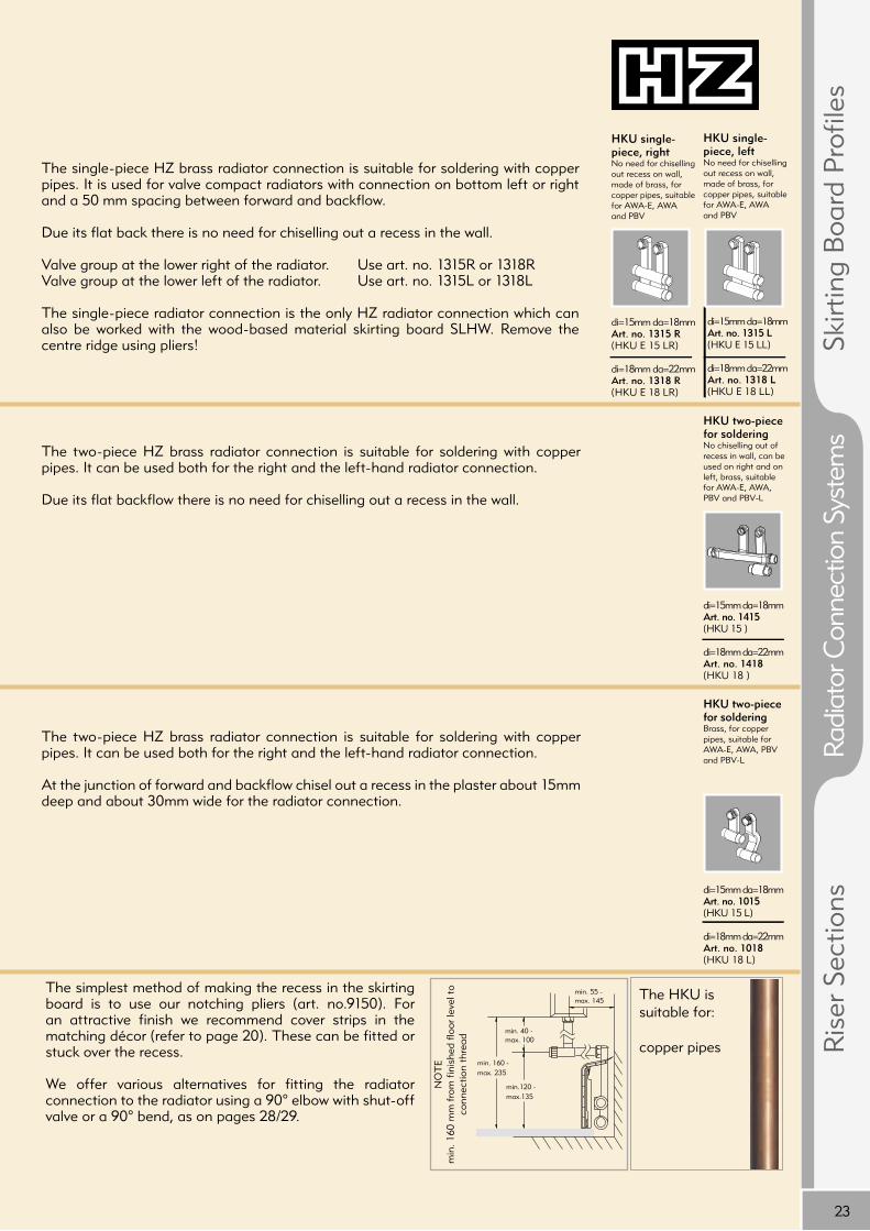
The two-piece HZ brass radiator connection is suitable for soldering with copper pipes. It can be used both for the right and the left-hand radiator connection.
Due its flat backflow there is no need for chiselling out a recess in the wall.
The single-piece HZ brass radiator connection is suitable for soldering with copper pipes. It is used for valve compact radiators with connection on bottom left or right and a 50 mm spacing between forward and backflow.
Due its flat back there is no need for chiselling out a recess in the wall.
Valve group at the lower right of the radiator. Use art. no. 1315R or 1318RValve group at the lower left of the radiator. Use art. no. 1315L or 1318L
The single-piece radiator connection is the only HZ radiator connection which can also be worked with the wood-based material skirting board SLHW. Remove the centre ridge using pliers!
The two-piece HZ brass radiator connection is suitable for soldering with copper pipes. It can be used both for the right and the left-hand radiator connection.
At the junction of forward and backflow chisel out a recess in the plaster about 15mm deep and about 30mm wide for the radiator connection.
HKU two-piece for solderingNo chiselling out of recess in wall, can be used on right and on left, brass, suitable for AWA-E, AWA, PBV and PBV-L
di=15mm da=18mmArt. no. 1415(HKU 15 )
di=18mm da=22mmArt. no. 1418 (HKU 18 )
HKU two-piece for solderingBrass, for copper pipes, suitable for AWA-E, AWA, PBV and PBV-L
di=15mm da=18mmArt. no. 1015(HKU 15 L)
di=18mm da=22mmArt. no. 1018 (HKU 18 L)
HKU single-piece, rightNo need for chiselling out recess on wall, made of brass, for copper pipes, suitable for AWA-E, AWA and PBV
di=15mm da=18mmArt. no. 1315 R(HKU E 15 LR)
di=18mm da=22mmArt. no. 1318 R(HKU E 18 LR)
HKU single-piece, leftNo need for chiselling out recess on wall, made of brass, for copper pipes, suitable for AWA-E, AWA and PBV
di=15mm da=18mmArt. no. 1315 L(HKU E 15 LL)
di=18mm da=22mmArt. no. 1318 L(HKU E 18 LL)
The HKU is suitable for:
copper pipes
NO
TE
min
. 160
mm
fro
m f
inis
hed
floor
leve
l to
conn
ectio
n th
read
The simplest method of making the recess in the skirting board is to use our notching pliers (art. no.9150). For an attractive finish we recommend cover strips in the matching décor (refer to page 20). These can be fitted or stuck over the recess.
We offer various alternatives for fitting the radiator connection to the radiator using a 90° elbow with shut-off valve or a 90° bend, as on pages 28/29.
Ris
er S
ectio
nsRa
diat
or C
onne
ctio
n Sy
stem
sSk
irtin
g B
oard
Pro
files

24
~13
1/2''
di
~255
7035
>15
~25,5
7035
di 96
~29
>15
~14
1/2"
~13
1/2''
di
7035
>15
~25,5
~245
HKU - Radiator connections for press-fi tting
Type Art. no. diHKU 15 VP 1515 15HKU 18 VP 1518 18
Radiator connection, two-piece for copper press-fi tting art. no. 1445/1448
Radiator connection, two-piece for copper press-fi tting art. no. 1515/1518
Radiator connection, two-piece for press-fi tting art. no. 1465/1468
Type Art. no. diHKU U 15 VP 1445 15HKU U 18 VP 1448 18
The upper pipe is the forward fl ow.The lower pipe is the backfl ow.
When using HZ skirting board profi les the following clearances must be observed between the connection thread of the radiator and the fi nished fl oor level:
When using SLF and SLT - at least 160 mmWhen using SLF 28-2000 - at least 180 mmWhen using SLL - at least 190 mm
If expansion of the pipes without stress is not possible, standard commercial expansion joints should be used.
Type Art. no. diHKU U 15 M 1465 15HKU U 18 M 1468 18
IMPORTANT for all HZ radiator connections for press-fi tting:
25
min. 40 -max. 100
min.120 - max.135
min. 55 - max. 145
min. 160 - max. 235
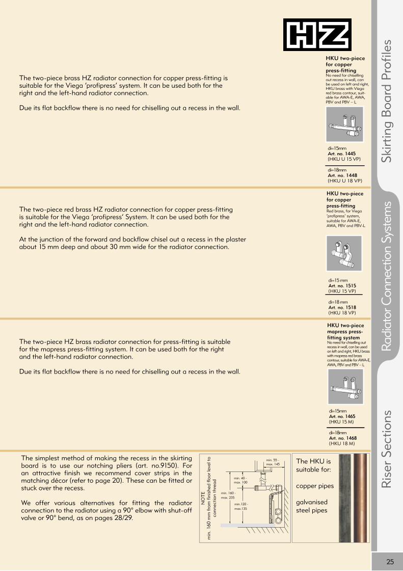
The two-piece red brass HZ radiator connection for copper press-fitting is suitable for the Viega ‘profipress’ System. It can be used both for the right and the left-hand radiator connection.
At the junction of the forward and backflow chisel out a recess in the plaster about 15 mm deep and about 30 mm wide for the radiator connection.
The two-piece brass HZ radiator connection for copper press-fitting is suitable for the Viega ‘profipress’ system. It can be used both for the right and the left-hand radiator connection.
Due its flat backflow there is no need for chiselling out a recess in the wall.
The two-piece HZ brass radiator connection for press-fitting is suitable for the mapress press-fitting system. It can be used both for the right and the left-hand radiator connection.
Due its flat backflow there is no need for chiselling out a recess in the wall.
HKU two-piece mapress press-fitting systemNo need for chiselling out recess in wall, can be used on left and right, HKU brass with mapress red brass contour, suitable for AWA-E, AWA, PBV and PBV – L
di=15mm Art. no. 1465(HKU 15 M)
di=18mmArt. no. 1468 (HKU 18 M)
HKU two-piece for copper press-fittingNo need for chiselling out recess in wall, can be used on left and right, HKU brass with Viega red brass contour, suit-able for AWA-E, AWA, PBV and PBV – L
di=15mm Art. no. 1445(HKU U 15 VP)
di=18mm Art. no. 1448(HKU U 18 VP)
HKU two-piece for copper press-fittingRed brass, for Viega ’profipress‘ system, suitable for AWA-E, AWA, PBV and PBV-L
di=15 mmArt. no. 1515(HKU 15 VP)
di=18 mmArt. no. 1518(HKU 18 VP)
The simplest method of making the recess in the skirting board is to use our notching pliers (art. no.9150). For an attractive finish we recommend cover strips in the matching décor (refer to page 20). These can be fitted or stuck over the recess.
We offer various alternatives for fitting the radiator connection to the radiator using a 90° elbow with shut-off valve or 90° bend, as on pages 28/29.
The HKU is suitable for:
copper pipes
galvanised steel pipes
Ris
er S
ectio
nsRa
diat
or C
onne
ctio
n Sy
stem
sSk
irtin
g B
oard
Pro
files
NO
TE
min
. 160
mm
fro
m f
inis
hed
floor
leve
l to
conn
ectio
n th
read
26
70
35
~25,5
194
>15
~13
da=3/4''
1/2''
70
35
~25,5
194
>15
~13
di=1/2''
1/2''
~13
1/2"
di
~233
7035
>15
~25,5
HKU – radiator connections with tapered seal, female thread and for copper push-fi tting
Type Art. no. diHKU 1/2 I 1412 1/2“
Two-piece radiator connection with 3⁄4” male thread/tapered seal art. no. 1434
Two-piece radiator connection with 1/2” female thread art. no. 1412
Radiator connection, two-piece for copper push-fi tting art. no. 1455/1458
Type Art. no. daHKU 3/4E 1434 3/4“
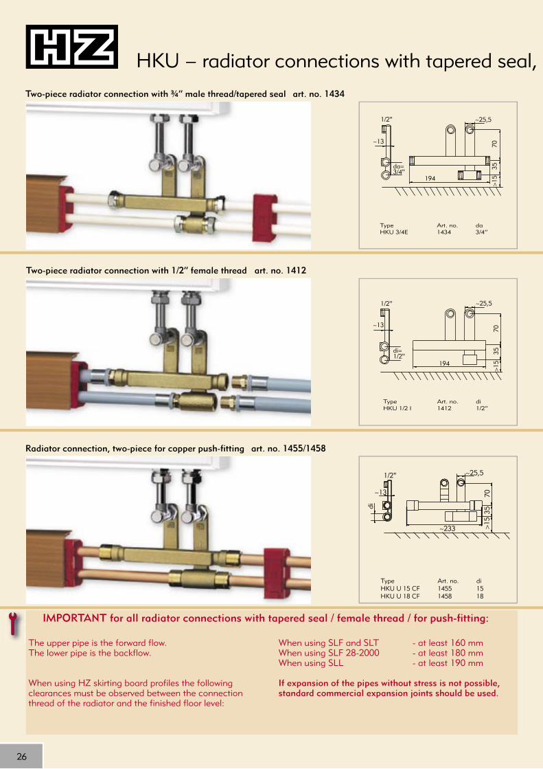
The upper pipe is the forward fl ow.The lower pipe is the backfl ow.
When using HZ skirting board profi les the following clearances must be observed between the connection thread of the radiator and the fi nished fl oor level:
When using SLF and SLT - at least 160 mmWhen using SLF 28-2000 - at least 180 mmWhen using SLL - at least 190 mm
If expansion of the pipes without stress is not possible, standard commercial expansion joints should be used.
IMPORTANT for all radiator connections with tapered seal / female thread / for push-fi tting:
Type Art. no. diHKU U 15 CF 1455 15HKU U 18 CF 1458 18

27
min. 40 -max. 100
min.120 - max.135
min. 55 - max. 145
min. 160 - max. 235
The two-piece HZ brass radiator connection is suitable for adaptor unions with 1⁄2” female thread. It can be used both for the right and the left-hand radiator connection.
Due its flat backflow there is no need for chiselling out a recess in the wall.
The two-piece HZ brass radiator connection with 3⁄4” male thread/tapered seal is suitable for composite pipes. The pipe is connected with an adaptor union fitting the 3⁄4” male thread/tapered seal from the relevant pipe manufacturer. It can be used both for the right and the left-hand radiator connection.
Due its flat backflow there is no need for chiselling out a recess in the wall.
HKU – radiator connections with tapered seal, female thread and for copper push-fitting
The two-piece HZ brass radiator connection for copper push-fitting is suitable for Cuprofit push-fit systems. Only DIN EN 1057 and RAL 641/1 tested copper pipe may be used. It can be used both for the right and the left-hand radiator connection.
Due its flat backflow there is no need for chiselling out a recess in the wall.
Observe the following steps in installation:
1. Cut the copper system pipe to length using a pipe cutter.2. Trim the end of the pipe carefully and calibrate with pin and ring.3. Mark the insert depth for the push-fitting.4. Slip the push-fitting onto the pipe as far as the marking.5. With soft copper pipe use appropriate support sleeves.
HKU, two-piece with 3⁄4” male thread/tapered sealFor composite pipes, no chiselling out of recess in wall, can be used on right and on left, brass, suitable for AWA-E, AWA, PBV and PBV-L
f. adaptor unionda= 3/4“ male thread / tapered sealArt. no. 1434(HKU 3/4 E)
HKU two-piece, 1⁄2” female threadNo chiselling out of recess in wall, can be used on right and on left, brass, for adapter union, suitable for AWA-E, AWA, PBV and PBV-L
di=1/2“Art. no. 1412(HKU 1/2 I)
HKU two-piece for copper push-fittingNo chiselling out of recess in wall, can be used on right and on left, brass, for Cuprofit push-fit system, suitable of AWA-E, AWA, PBV and PBV-L
di=15mmArt. no. 1455(HKU U 15 CF)
di=18mm Art. no. 1458 (HKU U 18 CF)
The simplest method of making the recess in the skirting board is to use our notching pliers (art. no.9150). For a more attractive finish we recommend cover strips in the matching décor (refer to page 20). These can be fitted or stuck over the recess.
We offer various alternatives for fitting the radiator connection to the radiator using a 90° elbow with shut-off valve or 90° bend, as on pages 28/29.
Ris
er S
ectio
nsRa
diat
or C
onne
ctio
n Sy
stem
sSk
irtin
g B
oard
Pro
files
NO
TE
min
. 160
mm
fro
m f
inis
hed
floor
leve
l to
conn
ectio
n th
read

28
1
2
3
4
5
6
7
1 2 3 4 5 6 7
min. 40 -max. 100
min.120 - max.135
min. 55 - max. 145
min. 160 - max. 235
min. 40 -max. 150
min. 120 - max. 135
min. 55 - max. 170
min. 160 - max. 285
The following applies to all HZ compression joints:
tighten the union nut as far as possible by hand and then one more turn max. using a spanner.
AWA the fast and fl exible connection between the HZ radiator connector and compact radiator with integrated valve
90° elbow with shut-off valve, can be shut off/drained art. nos. 1022/102390° elbow with shut-off valve, can be drained, nickel plated
Made of copper pipe with compression joint 1⁄2”, Ø 15 mm, for connection between HZ HKU and compact radiator with integrated valve, nickel plated, no. required: 1 pair/HZ radiator connection
Art. no. 1023(AWA-E)
90° elbow with shut-off valve, nickel plated
Made of copper pipe with compression joint 1⁄2”, Ø 15 mm, for connection between HZ HKU and compact radiator with integrated valve, nickel plated, no. required: 1 pair/HZ radiator connection
Art. no. 1022(AWA)
• can be shut off
• can be drained ( art no. 1023)
• 15 mm copper pipe, nickel plated
• fi ts all HZ radiator connections
• Length: 125 mm Height: 100 mm
• can be trimmed to required height and depth
• incl. compression joint to the radiator connector
• compression joint between 90° elbow and the radiator art. nos. 1025 / 1026 see page 29
• Cock block not required
• can be shut off
• 15 mm copper pipe, nickel plated
• fi ts all HZ radiator connections
• Length: 150 mm Height: 150 mm
• can be trimmed to required height and depth
• incl. compression joint to the radiator connector
• compression joint between 90° elbow and the radiator art. nos. 1025 / 1026 see page 29
• Cock block not required
90° elbow with shut-off valvelong, nickel plated
Made of copper pipe with compression joint 1⁄2”, Ø 15 mm, length of the pipe sockets: 150 mm, for connecting HZ HKU and compact radiator with integrated valve. no. required: 1 pair/HZ radiator connection
Art. no. 1022L(AWA-L)
90° elbow with shut-off valve, can be shut off/ long art. no. 1022L
Adjustment of fl ow rate for art. nos. 1022, 1023 und 1022L
Note:min. 160 mm from fi nished fl oor level
to connection thread
Note:min. 160 mm from fi nished fl oor level
to connection thread
Turns of adjusting nipple
2,5 turns
3,5 turns
4,5 turns
5,5 turns
6,5 turns
7,5 turns
8,5 turns
dp [bar] flow restrictor [m3/h]: 0,42 0,71 0,94 1,29 1,66 2,07 2,461
0,1
0,01 50 100 500 1000 2000 3000 5000 Flow [l/h]

29
min. 40 -max. 70
min.120 - max.135
min. 160 - max. 205
min. 65 - max. 130
min. 160 - max. 1135
min. 40 -max. 1000
min.120 - max.135
min. 65 - max. 130
AWA the fast and fl exible connection between the HZ radiator connector and compact radiator with integrated valve
90° bendnickel plated
Made of copper pipe with compression joint 1⁄2”, Ø 15 mm, for connection between HZ HKU and compact radiator with integrated valve No. required: 1 pair/HZ radiator connection
Art. no. 1021(PBV)
• 15 mm copper pipe, nickel plated
• fi ts all HZ radiator connections
• Length: 115 mm Height: 72 mm
• can be trimmed to required height and depth
• incl. compression joint to the radiator connector
• compression joint between 90° bend and the radiator art. nos. 1025 / 1026 see below
• Cock block not required
90° bend, long,chromium plated
Made of precision steel tube with compression joint 1⁄2”, Ø 15 mm, for radiators with lateral connection using HZ HKU two-piece,no. required:1 pair/HZ radiator connection
Art. no. 1031(PBV-L)
• 15 mm precision steel tube, chromium plated
• Length: Forward fl ow 1000 mm Backfl ow 72 mm Height: Forward fl ow 120 mm Backfl ow 115 mm
• can be trimmed to required height and depth
• forward fl ow with thermostat head and backfl ow must be valve in axial or angular form with locking ring for 15 mm Ø
• incl. compression joint to the radiator connector
• 90° bend 1031 for fi tting two-piece, fl at radiator connections (14XX) can only be used with composite pipes up to 20 mm Ø or with copper pipes up to 18 mm Ø • compression joint between 90° bend and the radiator art. nos. 1025 / 1026 see below
• Cock block not required
90° bend art. no. 1021
90° bend art. no. 1031
Note:min. 160 mm from fi nished fl oor level
to connection thread
Note:min. 160 mm from fi nished fl oor level
to connection thread
PBV the fast and fl exible connection between the HZ radiator connector and compact radiator with integrated valve
Compression joint art. no. 1026 (KVI)
With self-sealing double nipple for fi tting 90° bend (PBV) or 90° elbow with shut-off valve (AWA-E, AWA) and the compact radiator with integrated valve with 1⁄2” female thread, nickel plated, package quantity: 10 pces
Compression joint art. no. 1025 (KVA)
for connecting 90° bend (PBV) or 90° elbow with shut-off valve (AWA-E, AWA)and compact radiator with integrated valve with 3/4” male thread, nickel plated, package quantity: 10 pces
Compression joint 15 x 1⁄2“ art. no. 1034 (KV 15)
To fi t the top connector for all HZ radiator connections, for CU and soft steel pipes, Ø 15 mm, nickel plated, package quantity: 10 pces
Compression joint for connecting AWA and PBV to the radiator
Ris
er S
ectio
nsRa
diat
or C
onne
ctio
n Sy
stem
sSk
irtin
g B
oard
Pro
fi les

30
Vdi
Hdi
Hda
Vda
70
70a
b
c
STK Riser unions
Specifi cations in mm
Vertical HorizontalArt.no. Vdi Vda Hdi Hda a b c12215 22 28 15 18 52 36 2512218 22 28 18 22 52 36 2512815 28 35 15 18 69 50 3712818 28 35 18 22 69 50 37
Riser union
from red brass, for solderingDiameter: vertical ID=22mm / OD=28mmhorizontal ID=18mm / OD=22mm
Art. no. 12218 (STK 22/18 L)
Riser union
from red brass, for solderingDiameter: vertical ID=22mm / OD=28mmhorizontal ID=15mm / OD=18mm
Art. no. 12215 (STK 22/15 L)
Riser union
from red brass, for solderingDiameter: vertical ID=28mm / OD=35mmhorizontal ID=15mm / OD=18mm
Art. no. 12815 (STK 28/15 L)
Riser union
from red brass, for solderingDiameter: vertical ID=28mm / OD=35mmHorizontal ID=18mm / OD=22mm
Art. no. 12818 (STK 28/18 L)
HZ riser unions allow you to save both space and time in installation for the transition from horizontal to vertical copper pipes. This convincing and inexpensive solution in red brass for soldering is available in four different sizes. This is where multi-storey pipe distribution is made easy!
For cladding junctions we recommend using the riser sections art. no. 980 and 6580 (see page 31).
If expansion of the pipes without stress is not possible, standard commercial expansion joints should be used.
31
114100
757 50
164150
782 75
214200
7107
100
264250
7157
150
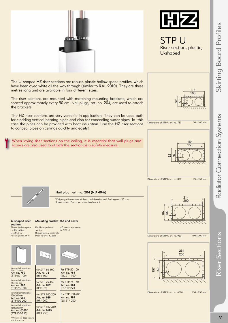
STP U Riser section, plastic, U-shaped
Dimensions of STP U art. no. 780
Dimensions of STP U art. no. 880
Dimensions of STP U art. no. 980
Dimensions of STP U art. no. 6580
Mounting bracket
For U-shaped riser sectionRequirements: 2 pces/metrePacking unit: 40 pces
for STP 50-100Art. no. 78(BFK 100)
for STP 75-150 Art. no. 889 (BFK 150)
for STP 100-200 Art. no. 989(BFK 200)
for STP 150-250 Art. no. 6589 (BFK 250)
U-shaped riser section Plastic hollow space profile, white, length:3 m Packing unit: 24 m
Internal dimensions 50x100 mmArt. no. 780(STP 50-100)
Internal dimensions 75x150 mmArt. no. 880(STP 75-150)
Internal dimensions 100x200 mmArt. no. 980(STP100-200)
Internal dimensions 150x250 mmArt. no. 6580*(STP150-250)
*With art. no. 6580 packing unit: 6 m in box
HZ end cover
HZ plastic end cover for STP U
for STP 50-100Art. no. 784(ES STP 100)
for STP 75-150 Art. no. 884(ES STP 150)
for STP 100-200 Art. no. 984(ES STP 200)
Nail plug art. no. 204 (ND 40-6)
Wall plug with countersunk head and threaded nail. Packing unit: 50 pcesRequirements: 2 pces. per mounting bracket
The U-shaped HZ riser sections are robust, plastic hollow space profi les, which have been dyed white all the way through (similar to RAL 9010). They are three metres long and are available in four different sizes.
The riser sections are mounted with matching mounting brackets, which are spaced approximately every 50 cm. Nail plugs, art. no. 204, are used to attach the brackets.
The HZ riser sections are very versatile in application. They can be used both for cladding vertical heating pipes and also for concealing water pipes. In this case the pipes can be provided with heat insulation. Use the HZ riser sections to conceal pipes on ceilings quickly and easily!
When laying riser sections on the ceiling, it is essential that wall plugs and screws are also used to attach the section as a safety measure.
Ris
er S
ectio
nsRa
diat
or C
onne
ctio
n Sy
stem
sSk
irtin
g B
oard
Pro
fi les
50 x 100 mm
75 x 150 mm
100 x 200 mm
150 x 250 mm

164157
782 75
214207
7107
100
214207
7
214
207
32
Dimensions of STP L art. no. 6280
Dimensions of STP L art. no. 6380
Dimensions of STP L art. no. 6480
Mounting bracketFor L-shaped riser sectionNumber required: 2 pces/metrePacking unit: 40 pces
for STP L 75-150 Art. no. 6289(BFK L 75-150)
for STP L 100-200Art. no. 6389(BFK L 100-200)
for STP L 200-2002x Art. no. 989*(BFK 200)
*4 pces per metre required
for STP 6480
L-shaped riser sectionWhite plastic hollow space profi le, length: 3 m, packing unit: 24 m in box
Internal dimensions 75x150mm Art. no. 6280(STP L 75-150)
Internal dimensions 100x200 mmArt. no. 6380(STP L 100-200)Internal dimensions 200x200 mmArt. no. 6480(STP L 200x200)
Nail plug art. no. 204 (ND 40-6)
Wall plug with countersunk head and threaded nail. Packing unit: 50 pcesNumber required: 2 pces. per mounting bracket
STP LRiser section, plastic, L-shaped
The L-shaped HZ riser sections are robust, plastic hollow space profi les, which have been dyed white all the way through (similar to RAL 9010). They are three metres long and are available in three different sizes.
The riser sections are mounted with matching mounting brackets, which are spaced approximately every 50 cm. Nail plugs, art. no. 204, are used to attach the brackets.
They are intended for cladding pipes laid in corners in particular. In this case the pipes can also be provided with heat insulation. They can also be used as skirting board profi les for larger pipes.
Four mounting brackets art. no. 989 are required per metre to install the riser section art. no. 6480.
75 x 150 mm
100 x 200 mm
200 x 200 mm

33
AccessoriesAccessories for riser sections
Butt joint cover section art. no. 6078 (ST STP)
For all HZ riser sections, white, self-adhesive, length: 1 m, packing unit: 25 m
Inspection door 15 x 15 cm art. no. 6018 (RT 15-15)
Sheet steel, for installing in STP no. 980, 6380, 6480, 6580, white
Flexible sealing lip art. no. 6088 (DLW)
For sealing the STP on the wall, white, self-adhesive, length: 3 m, packing unit: 48 m
Riser rosette art. no. 6082 (STR 22)
For pipe outlets at the side of riser sections, suitable for pipes up to 22 mm
Riser rosette art. no. 6081 (STR 18)
For pipe outlets at the side of riser sections, suitable for pipes up to 18 mm
Nail plug art. no. 204 (ND 40-6)
Wall plug with countersunk head and threaded nail.Packing unit: 50 pces. Number required: 2 pces. per mounting bracket
Inspection door 15 x 20 cm art. no. 6028 (RT 15-20)
Sheet steel, for installing in STP no. 980, 6380, 6480, 6580, white
Inspection door 15 x 25 cm art. no. 6038 (RT 15-25)
Sheet steel, for installing in STP no. 980, 6380, 6480, 6580, white
HZ lifting tool art. no. 9151 (AW)
For removing HZ riser sections
Ris
er S
ectio
nsRa
diat
or C
onne
ctio
n Sy
stem
sSk
irtin
g B
oard
Pro
files
34
+49 (0) 6132 / 78 36 21Fax reply to Hans Weitzel GmbH & Co. KGIngelheim am Rhein
or download from: http://www.hz-weitzel.deRequest for Promotional Material
We are a Plumbing and fitting company Wholesaler Educational institution End consumer Property company Planner Other
Date:
(Please complete missing information in capitals in dark-coloured ink, if this is not included in your fi rm‘s stamp.)
Customer reference:
Company:
Attn / Position:
Street no.:
Postal code City:
Country:
Language for correspondance:
Tel.:
Fax.:
Email:
Please send us free of charge and without obligation:
HZ sample box incl.
HZ Main Catalogue
HZ Price List
HZ Installation Instructions
HZ End Consumer Folder
Sample of art. no.
We want more! We would like ...........
Visit by representative from sales force Telephone consultation

+49 (0) 6132 / 78 36 21Fax reply to Hans Weitzel GmbH & Co. KGIngelheim am Rhein
or download from: http://www.hz-weitzel.de
Since the company was founded in 1963 the idea of pipe cladding for pre-wall installation has given rise to an all-round package for heating and piping. Nowadays our family business which is rich in tradition presents itself as a system provider for pre-wall installation with three product groups. Apart from the skirting board profi les developed by Hans Weitzel we also offer the HZ riser sections for vertical pipe cladding and the HZ connector groups for fi tting radiators.
Over the past decades HZ has proven its spirit of innovation again and again. The range of HZ 2000 Skirting Boards was launched on the market a while back. The advantages in installation, typical of HZ, have been further improved on.
Our modern production sites are in Ingelheim am Rhein, about 60 km south west of Frankfurt am Main. This is where our high-quality products are manufactured under constant quality control in state-of-the-art production sites in round-the-clock operation. Environmentally friendly production is a particularly high priority here.
Service for our customers in the western states of Germany and abroad is managed at our headquarters in Ingelheim, to which a modern logistics centre is attached. Our customers in the eastern part of Germany, the new states, are served by our branch founded in 1997 in Radefeld near Leipzig. The export department has been expanded in order to meet the demand stemming from an increasing presence in foreign markets.
Sales of our products are handled via trade wholesalers and guarantee you prompt availability.
Please send us free of charge and without obligation:
HZ sample box incl.
HZ Main Catalogue
HZ Price List
HZ Installation Instructions
HZ End Consumer Folder
Sample of art. no.
Stei
gstr
angp
rofil
eH
eizk
örpe
ranb
inde
syst
eme
Hans Weitzel GmbH & Co. KGKonrad-Adenauer-Straße 20D-55218 Ingelheim
Export:
Tel.: +49 (0) 61 32 / 790 89 - 10
Tel.: +49 (0) 61 32 / 790 89 - 12
Fax: +49 (0) 61 32 / 78 36 - 10
Fax: +49 (0) 61 32 / 78 36 - 12
e-mail: [email protected]
www.hz-weitzel.de