GeoWest Engineering Ltd. - newwestcity.ca
24
GeoWestEngineeringLtd. 200∙34425McConnellRoad,Abbotsford,BCV2S7P1 www.geowestengineering.com [email protected]|604∙852∙9088 GeotechnicalandEnvironmentalConsultants AbbotsfordLangley 19October2018 GeoWestFile: GA18-1251-00 WedlerEngineeringLLP #202–10216–128Street Surrey,BCV3T2Z5 Attention: Mr.StanReid,P.Eng.–Partner,ProjectEngineer Viaemail: [email protected] Project: CityofNewWestminsterNWRFP-18-13–EngineeringServices,PhillipsStreetRoadwayDesign Subject: GeotechnicalAssessmentReport DearSir, 1. INTRODUCTION At the request of Wedler Engineering LLP on behalf of the City of New Westminster (the Client), GeoWest Engineering Ltd. (GeoWest) provides herein a geotechnical assessment report for the proposed road improvementsdetailedintheCityofNewWestminsterNWRFP-18-13. Thisgeotechnicalassessmentreporthasbeencompletedinaccordancewithourproposaldated12June2018 andapprovedbyWedlerEngineeringLLPon10September2018. Thepurposeofthegeotechnicalassessmentwastoestablishthesubsurfaceconditionsatthesiteandtoprovide relatedgeotechnicaldiscussionandrecommendationsinregardtoproposedtrenches,beddingandbackfillfor thenewstormpipes,sitepreparationandnewpavementinroadwideningareas,andforrehabilitationofthe existingpavementwherepossible. 2. PROPOSEDCONSTRUCTION WeunderstandthattheCityofNewWestminsterintendstoproceedwithutilityandroadimprovementson PhillipsStreetbetweenEwenAvenueandCanilAvenue,whichencompassesatotalroadlengthofapproximately 175mandisshownontheattachedFigure1. Atthetimeofthepreparationofthisreport,designdrawingsfortheproposedimprovementswerenotavailable. Forourutilitytrenchrecommendations,wehaveproceededontheassumptionthattheinvertofthenewpipe will approximately match the existing ditch invert, which is approximately 0.6 to 0.9 m below existing road surfaceelevations.
Transcript of GeoWest Engineering Ltd. - newwestcity.ca

GeoWest Engineering Ltd. 200 ∙ 34425 McConnell Road, Abbotsford, BC V2S 7P1
www.geowestengineering.com
[email protected] | 604∙852∙9088
Geotechnical and Environmental Consultants
Abbotsford Langley
19 October 2018
GeoWest File: GA18-1251-00
Wedler Engineering LLP
#202 – 10216 – 128 Street
Surrey, BC V3T 2Z5
Attention: Mr. Stan Reid, P.Eng. – Partner, Project Engineer
Via email: [email protected]
Project: City of New Westminster NWRFP-18-13 – Engineering Services, Phillips Street Roadway Design
Subject: Geotechnical Assessment Report
Dear Sir,
1. INTRODUCTION
At the request of Wedler Engineering LLP on behalf of the City of New Westminster (the Client), GeoWest
Engineering Ltd. (GeoWest) provides herein a geotechnical assessment report for the proposed road
improvements detailed in the City of New Westminster NWRFP-18-13.
This geotechnical assessment report has been completed in accordance with our proposal dated 12 June 2018
and approved by Wedler Engineering LLP on 10 September 2018.
The purpose of the geotechnical assessment was to establish the subsurface conditions at the site and to provide
related geotechnical discussion and recommendations in regard to proposed trenches, bedding and backfill for
the new storm pipes, site preparation and new pavement in road widening areas, and for rehabilitation of the
existing pavement where possible.
2. PROPOSED CONSTRUCTION
We understand that the City of New Westminster intends to proceed with utility and road improvements on
Phillips Street between Ewen Avenue and Canil Avenue, which encompasses a total road length of approximately
175 m and is shown on the attached Figure 1.
At the time of the preparation of this report, design drawings for the proposed improvements were not available.
For our utility trench recommendations, we have proceeded on the assumption that the invert of the new pipe
will approximately match the existing ditch invert, which is approximately 0.6 to 0.9 m below existing road
surface elevations.

City of New Westminster NWRFP-18-13
Engineering Services, Phillips Street Roadway Design
Geotechnical Assessment Report
19 October 2018
File: GA18-1251-00
Page 2
The civil design drawings should be provided to GeoWest for review in advance of tendering to confirm the
assumptions and recommendations contained herein.
3. SITE DESCRIPTION
The area of the proposed work is located in the Queensborough neighbourhood of New Westminster. The
subject portion of Phillips Street is located within a residential subdivision bordered by residential homes and
townhomes.
Phillips Street is a relatively narrow, two-lane asphalt paved road with gravel or grass covered shoulders on both
sides of the road for the full length of the assessment area. The visual condition of the asphalt varies, in our
opinion, from fair to poor with the asphalt surface estimated to be in excess of 20 years old and possessing
multiple areas of cracked pavement and utility and pothole patches. Further discussion regarding our pavement
assessment is provided in Section 6.2.
The topography of the assessment area is relatively flat with an elevation of about 1 m, geodetic, according to
the City of New Westminster GIS.
4. FIELD WORK
4.1. Drill Investigation
A drill-based investigation was completed on 3 October 2018. A total of 4 auger holes were drilled using a
subcontracted, truck-mounted auger drill rig supplied and operated by Downrite Drilling Ltd. of Chilliwack, BC.
The approximate locations of the auger holes are shown on Figure 2.
The auger holes were drilled to a depth of 4.6 m below current local grades. All auger holes were logged in the
field by a member of our engineering staff and backfilled immediately upon completion of testing and logging in
accordance with provincial groundwater protection regulations. The auger holes were sealed with a surface
treatment of asphalt cold patch. Selected samples were collected from the auger flights for routine laboratory
index testing. The test hole logs are presented in Appendix A, following this report. The laboratory results are
included on the relevant test hole logs.
A Dynamic Cone Penetration Test (DCPT) was conducted at borehole AH18-02. The DCPT is widely used by local
geotechnical practitioners and is conducted by advancing a steel cone with the same diameter as a standard split
barrel sampler into the ground using an automatic trip hammer with a weight of 63 kg and a free-fall drop of 750
mm (the same driving energy used for the Standard Penetration Test [SPT]). The number of blows required for
each 305 mm interval of depth of advancement of the cone is recorded. The blow counts for the DCPT provide a
continuous indication of the in-situ relative density / consistency of the soils. However, this test method is not
an ASTM recognized procedure, nor is it universally accepted as a reliable alternative to SPT testing. The DCPT
data is included on the relevant test hole log.

City of New Westminster NWRFP-18-13
Engineering Services, Phillips Street Roadway Design
Geotechnical Assessment Report
19 October 2018
File: GA18-1251-00
Page 3
4.2. Benkelman Beam Testing
Benkelman Beam Testing (BBT) was conducted in both the northbound and southbound lanes of Phillips Street
between Ewen Avenue and Canil Avenue by Metro Testing Laboratories (MTL) of Burnaby, BC. The BBT is a non-
destructive test of the pavement that consists of the measurement of the rebound of the pavement after being
subjected to the load of a dual-tired single axle loaded to 18,000 lbs. The data is collected in set intervals and
adjusted for temperature and seasonal effects. The average of the data plus two standard deviations yields the
Most Probable Spring Rebound (MPSR). This value may be correlated to City pavement design standards and
design traffic volumes to assist in the assessment of the ability of the existing pavement to support current and
future traffic volumes.
The BBT was completed at 10 m intervals, alternating between the inner and outer wheel path. Station 0+00 is
located at the intersection of Canil Avenue and Phillips Street. Station 1+40 is identified by MTL as being located
at the driveway to 1330 Ewen Avenue. A total of 30 rebound values were recorded with 15 in each of the
northbound and southbound lanes.
The BBT data is presented in Appendix B for reference and discussed in Section 6.2.
5. SITE CONDITIONS
5.1 Surficial Geology
According to Geological Survey of Canada (GSC) Surficial Geology Map 1484A, the site is underlain by post-glacial
sediments (SAb) which include “bog, swamp, and shallow lake deposits”. For the SAb deposit, this specifically
includes “lowland peat up to 14 m thick, in part overlying Fb, Fc” (Fraser River sediments). The GSC map also
suggests that peat deposits are lacking to the south of Canil Avenue.
The drilling indicates general conformance with the above referenced geology.
5.2 Soil Conditions
The test hole logs should be referred to for the specific soil conditions at each auger hole location. The test hole
logs attached to this report provide description of the soil conditions encountered at discrete locations. Actual
soil conditions remote from the boreholes may vary. Contractors should make their own interpretation of the
test hole logs and the site conditions for the purposes of bidding and performing work at the site.
A summary of the conditions at the boreholes is provided below.
5.2.1 Fill
All auger hole locations were surfaced with asphalt, with the thickness of asphalt varying from
approximately 32 to 50 mm. The pavement structure fill below the asphalt consisted of compact to dense
sand and gravel. The sand was specifically observed to be medium grained and the gravel was generally
City of New Westminster NWRFP-18-13
Engineering Services, Phillips Street Roadway Design
Geotechnical Assessment Report
19 October 2018
File: GA18-1251-00
Page 4
less than 50 mm in diameter and sub-rounded. This fill was observed to extend to depths of 0.6 to 0.9 m
below the ground surface.
5.2.2 Organic Silt and Peat
Organic silt and peat were observed below the pavement structure fills at all auger hole locations and
extended to depths of 3.8 to 4.1 m below current elevations.
The peat was observed to be dark brown, very soft, moist to saturated and fibrous to semi amorphous.
The total thickness of peat at the auger hole locations varied from 1 to 1.8 m with moisture contents
ranging from 363 to 751%.
The organic silt was observed to be brown to dark brown, moist to saturated, very soft and had inclusions
of peat. The total thickness of the organic silt varied from 1.5 to 2 m with moisture contents varying
between 122 and 518%.
The moisture contents indicate that both the peat and organic silt will exhibit very high compressibility
under new loading. The organic component of both materials will also result in unavoidable long-term
settlements due to gradual decay of these materials.
5.2.3 Overbank Silt (Fraser River Sediments)
The organic silt and peat is underlain by grey, very soft, moist silt with some fibrous peat. Moisture
contents of this material ranged from 77 to 178% at the borehole locations, indicating that this deposit
will exhibit high compressibility under new loads.
This deposit extended to the full depth of exploration at all auger hole locations.
5.3 Groundwater Conditions
The static groundwater table was observed at the time of our investigation at depths of about 0.6 to 0.9 m below
current road elevations. The moisture contents of the soils in the auger holes correspond with observed water
levels in the ditch on the west side of Phillips Street. Water levels in the area are expected to vary seasonally,
with generally higher water levels after periods of prolonged precipitation, and to a lessor extent tidally.
It should be appreciated that, due to the relatively low elevation of the site at approximately 1 m, geodetic, this
area of New Westminster may be subject to periodic flooding.
Perched water should also be expected to develop during wetter periods of the year in the surficial fills overlying
the relatively low permeability organic silt and peat.

City of New Westminster NWRFP-18-13
Engineering Services, Phillips Street Roadway Design
Geotechnical Assessment Report
19 October 2018
File: GA18-1251-00
Page 5
6. DISCUSSIONS AND RECOMMENDATIONS
6.1 General
Phillips Street is designated as a local road between Canil Avenue and Ewen Avenue. The City of New
Westminster’s minimum pavement standard for local roads is as follows: 85 mm asphalt, 230 mm granular base
and 300 mm granular subbase.
The existing thickness of asphalt does not meet the City’s design specifications. As well, the gradation of the
existing fill does not likely meet the gradation requirements for granular base. The total thickness of the existing
pavement structure does exceed the above referenced City standard, but it is inadequate in our opinion for the
natural soil conditions.
The natural soil conditions directly underlying the pavement structure are comprised of highly compressible
deposits of peat, organic silt, and overbank silt. Existing road elevations should be maintained, if possible. Very
nominal grade increases are likely to trigger settlement that may be impactful to existing structures and
specifically gravity-based utilities.
Unavoidable long-term settlements of Phillips Street will occur due to the gradual decay of the organic
component of the peat and organic silt. There are no methods to accurately calculate the magnitude of
settlement generated the decay of organics. However, our general experience indicates that settlements may be
on the order of 150 to 200 mm over the next 15 to 20 years provided that existing grades are maintained. These
settlements will not necessarily occur in a uniform manner and so differential settlements should be expected,
which may be impactful to gravity-based utilities and the road structure.
6.2 Existing Pavement Structure
As noted in Section 3 the existing asphalt is in relatively fair to poor condition. The MPSR obtained from the BBT
data has been determined to be 7.28 mm. The City of New Westminster’s maximum permissible MPSR for a local
road is 1.50 mm. The measured MPSR substantially exceeds the allowable value and is a function, in our
considered opinion, of a combination of an inadequately thick pavement structure and the underlying very soft
natural soil conditions.
An asphalt overlay of the existing pavement surface, which is commonly undertaken to reduce pavement
deflections, is not considered practical as extrapolation between the in-situ MPSR to design MPSR yields a
required asphalt overlay in excess of 300 mm. Therefore, we recommend complete reconstruction of the Phillips
Street pavement structure between Canil Avenue and Ewen Avenue. Our recommendations for new pavement
are provided in Section 6.4.
6.3 Pavement Subgrade Preparation
Prior to construction of new pavement structures stripping of all existing asphalt and any other loose or
otherwise disturbed materials must be completed to expose a subgrade of sand and gravel fill or brown to dark

City of New Westminster NWRFP-18-13
Engineering Services, Phillips Street Roadway Design
Geotechnical Assessment Report
19 October 2018
File: GA18-1251-00
Page 6
brown, very soft peat to organic silt. We expect that the stripping depths will be dictated by the thickness of the
new pavement structure, presuming that existing grades are maintained, rather than the soil conditions.
The stripping of unsuitable soils must extend out beyond the road edges based on a 1H:1V (Horizontal:Vertical)
ratio. For example, if the depth of stripping is 1 m at the edge of the road, then all unsuitable soils should be
excavated horizontally 1 m beyond the road as well. The Geotechnical Engineer should review the exposed
subgrade to confirm that the unsuitable soils are removed.
The existing sand and gravel fill may be retained for use as subbase in the new pavement structure. The condition
of the fill will have to be assessed as it is exposed to confirm its suitability for re-use. If additional fills are required
to reinstate grade then Select Granular Subbase (SGSB), per the Master Municipal Construction Documents
(MMCD) gradation specifications, should be employed.
No vehicles or other equipment should traverse directly on the stripped pavement subgrade. It should be
protected prior to filling with a layer of non-woven Geotex 351 filter cloth, or equivalent pre-approved by
GeoWest. Due to the soft and weak subgrade conditions, the initial lift of pavement structure fill placed on the
subgrade soils should be 600 mm thick. The initial lift should be compacted with small “walk-behind” roller
compactors or similar small width (1.2 m or less) ride-on compactors. It should be appreciated that, due to the
required thickness of this lift and the weaker subgrade conditions, some additional compactive effort will be
required to achieve a satisfactory degree of compaction. Larger compaction equipment must not be employed
on the initial lift due to the potential to cause punching and shear failures of the underlying soils. After
completion of the initial lift of fill, subsequent lifts should not exceed 300 mm.
All fills should be compacted in-situ to at least 95% Modified Proctor maximum dry density (MPD). Compaction
should be confirmed by in-place soil density testing conducted by the Geotechnical Engineer at the time of fill
placement.
Seepage will likely be encountered at the time of stripping. Seepage volumes may be relatively heavy if perched
groundwater or high static groundwater conditions exist at the time of the work. Seepage rates can be limited
to some extent by limiting the subgrade preparation to discrete panels rather than a large open excavation.
Standing water must not be allowed to accumulate on the excavated subgrade and must be pumped off-site to
appropriate discharge facilities.
6.4 New Pavement
Based on the natural soil conditions observed at the test hole locations, it is our opinion that the implementation
of the City of New Westminster’s minimum local design pavement structure on Phillips Street is likely to result
in premature degradation of that pavement and associated elevated long-term maintenance requirements. We
recommend that the pavement structure provided in Table 1 be employed for new pavement construction on
Phillips Street.

City of New Westminster NWRFP-18-13
Engineering Services, Phillips Street Roadway Design
Geotechnical Assessment Report
19 October 2018
File: GA18-1251-00
Page 7
Table 1: Recommended Pavement Structure for Phillips Street, Canil Avenue to Ewen Avenue
Material Thickness (mm)
Asphalt 85
Road Base 230
Subbase 700
Geotex 351 non-woven filter cloth -
Geotechnical Engineer Approved Subgrade -
The gradation of the pavement structure materials should conform with the MMCD specifications with all fills
compacted to 95% MPD.
Quality control and assurance testing should be completed in accordance with City of New Westminster
requirements.
Incorporation of the recommended pavement structure will result in the excavation of peat and replacement
with heavier subbase fill. This will likely generate some settlement. Therefore, we recommend that once the
filter cloth, subbase, and base is in place that the road right-of-way be allowed to settle prior to final paving with
asphalt. Due to the variability of the natural soils below the site the settlements generated by filling will be
correspondingly variable as well. We suggest as an initial approximation that the top of the road base elevation
be set at the proposed top-of-asphalt elevation. Some additional filling or cutting of the base may be required
after the road settles and prior to paving, which we estimate to be about a 4 week period. Settlements should
be monitored with settlements gauges as per the procedure outlined in Section 6.5. Alternatively, the thickness
of peat that is removed can be replaced with the equivalent thickness of light weight fill to limit the settlements
generated by the new pavement structure and allow installation of the asphalt surface to proceed immediately.
For example, if 400 mm of peat was removed, it would be replaced with 400 mm of light weight fill followed by
300 mm of subbase to achieve the required total subbase design thickness of 700 mm. The design thickness of
the base and asphalt remain unchanged. Geotex 351 filter cloth may be required to separate the light weight fill
and subbase subject to the gradation of the two fills. Our recommended light weight fill specifications are
provided in Section 6.5.
The intent of the above referenced road site preparation and design recommendations is to balance, to the
extent possible, the reasonable life expectancy of the pavement and the impacts of long-term settlement. The
recommendations provided herein are on the basis of attempting to limit the magnitude of settlement of the
finished asphalt pavement surface and correspondingly achieve as long a pavement structure life as possible.
Irrespective of the implementation of these recommendations, it should be expected that the long-term
maintenance requirements for Phillips Street are likely to be higher than for other areas of New Westminster
that are underlain by more competent soils.
If there are any existing settlement sensitive utilities or other structures located within the Phillips Street right-
of-way then we recommend that the light weight fill option be solely employed.

City of New Westminster NWRFP-18-13
Engineering Services, Phillips Street Roadway Design
Geotechnical Assessment Report
19 October 2018
File: GA18-1251-00
Page 8
6.5 Ditch Infill
Prior to filling of the ditch all existing vegetation, topsoil and any other loose or deleterious materials must be
stripped to expose a subgrade of sand and gavel fill or brown to dark brown very soft peat to organic silt. The
ditch should be kept free of standing water during pipe installation and backfilling. The minimum depth of
stripping should be to the invert of the proposed storm sewer + diameter of the pipe. For example, if the
proposed sewer is 450 mm in diameter and the invert is 0.1 m, geodetic, then stripping should extend to -0.35
m, geodetic.
If grade is to be reinstated with conventional mineral fill, then we recommend that this material be placed to
finished elevations after the completion of the stripping to allow for consolidation of the natural soils. We
estimate that settlements will take approximately 4 weeks to occur. Settlements should be monitored with
settlement gauges placed at least every 25 m and monitored by a BC Licensed Surveyor (BCLS) on a weekly basis.
Survey results should be provided to GeoWest for review. Construction of utilities or road widening into the ditch
infill area should not proceed until directed otherwise by GeoWest.
Alternatively, construction of the new storm sewer and road may proceed immediately if light weight fill is used
to reinstate grade in the ditch after site stripping. This would entail the use of light weight fill as pipe bedding
and trench backfill as well. Light weight fills should consist of pumice or vesicular basalts, or other material pre-
approved by GeoWest, with a maximum saturated unit weight of 12 kN/m3. Styrofoam may also be considered
for use, subject to the final grading and utility designs. Where placed at shallow elevations Styrofoam may be
subject to the risk of flotation during high water table events and overstressing due to pavement structure
loading. Light weight granular fills can also be gap graded, which may require the incorporation of a non-woven
filter cloth into the design to prevent migration of fine-grained particles.
GeoWest can provide definitive recommendations for the ditch infill and utility installation process once the civil
design is further refined.
6.6. Utility Installation
We expect that the new storm sewer inverts will approximately match the existing ditch invert elevations, which
are about 0.6 to 0.9 m below current road elevations. The proceeding recommendations are based on that
scenario. The civil design drawings should be provided to GeoWest in advance of tendering to confirm the
recommendations provided herein.
The subgrade soils are soft, weak and moisture sensitive. Any seepage or rainwater entering the excavation
should be pumped to maintain dry conditions. We expect that inflows would be handled with conventional sump
pumps. However, as noted in Section 6.3, seepage rates may be high during elevated groundwater table
conditions. It should also be appreciated that, during flood conditions, pipe installation work is not likely to be
feasible.
The trench subgrade should be protected with pipe bedding material immediately after review and prior to
worker entry. The base of the trench should be excavated to one pipe diameter below the invert of the sewer.

City of New Westminster NWRFP-18-13
Engineering Services, Phillips Street Roadway Design
Geotechnical Assessment Report
19 October 2018
File: GA18-1251-00
Page 9
The utility trench bedding and backfill should be in accordance with MMCD Drawing No. G4. Imported pipe
bedding should meet the gradation requirements stated in MMCD Platinum Edition Section 31 05 17, Article 2.7,
Type 1 bedding, or as directed otherwise by the City of New Westminster. Imported trench backfill should meet
the requirements for the materials stated in MMCD Platinum Edition Section 31 23 01, Article 3.5 or as directed
otherwise by the City of New Westminster. The utility trench backfill should be compacted to 95% MPD. Note
that these MMCD approved materials are only suitable for use if the ditch is infilled with conventional mineral
fills and allowed to settle, as discussed in Section 6.5. Alternative light weight bedding and backfill will be required
if construction is desired to proceed immediately.
Due to the anticipated relatively shallow depth of the new storm sewer, we expect that the temporary slopes
would be cut at up to 1H:1V. Temporary slopes should be covered with poly sheeting. Any excavation in excess
of 1.2 m in depth requiring worker-entry should be sloped or shored in accordance with the latest Work Safe BC
Occupational Health & Safety guidelines, or under the direction of a professional geotechnical engineer
experienced in excavation design.
6.7 Geotechnical Review
Sufficient field reviews during construction should be conducted by the Geotechnical Engineer to ensure that the
geotechnical design recommendations contained within this report have been adequately communicated to the
design team and to the contractors implementing the design. These field reviews are not carried out for the
benefit of the contractors and therefore do not in any way affect the contractor’s obligations to perform under
the terms of their contract.
It is the contractors’ responsibility to advise GeoWest (a minimum of 48 hours in advance) that a field review is
required. Geotechnical field reviews are normally required at the time of the following:
1. Stripping – Review of stripping depth to suitable subgrade materials
2. Pavement Structure – Review of pavement structure fill gradation testing and compaction results
3. Subgrade – Review of trench subgrade prior to bedding placement
4. Backfill – Review of trench backfill gradation testing and compaction results
5. Temporary Excavations – Review of any excavation in excess of 1.2 m depth requiring worker entry
It is critical that these reviews are carried out to ensure that our intentions have been adequately communicated.
It is also critical that contractors working on the site view this document in advance of any work being carried
out so that they become familiarised with the sensitive aspects of the works proposed. It is the responsibility of
the Client and contractor to notify GeoWest when conditions or situations not outlined within this document are
encountered.
GeoWest accepts no responsibility for any geotechnical related aspects of the design which are not specifically
reviewed and approved by GeoWest at the time of construction.

City of New Westminster NWRFP-18-13
Engineering Services, Phillips Street Roadway Design
Geotechnical Assessment Report
19 October 2018
File: GA18-1251-00
Page 10
7. CLOSURE
This geotechnical engineering assessment report has been prepared by GeoWest Engineering Ltd. exclusively for
Wedler Engineering LLP and the City of New Westminster. The information contained in this report reflects our
judgement in light of the information provided to us at the time it was prepared.
Any use of this report by third parties, or any reliance on or decisions made based on it, are the responsibility
of such third parties. GeoWest does not accept responsibility for damages suffered, if any, by a third party as a
result of their use of or reliance on this report.
The attached Terms of Reference are an integral part of this report.
GeoWest trusts this meets your immediate requirements. If you have any questions or require further
information, please contact us.
Yours truly,
GeoWest Engineering Ltd.
REVIEWED BY:
Per: John Carter, M.Eng, P.Eng. Michael Gutwein, P.Eng.
Senior Geotechnical Engineer Senior Geotechnical Engineer
Attachments: Terms of Reference
Figure 1
Figure 2
Appendix A – Geotechnical Borehole Logs
Appendix B – Benkelman Beam Test Results

TERMS OF REFERENCE FOR GEOTECHNICAL REPORTS ISSUED BY GEOWEST ENGINEERING LTD.
Page 1 of 2
1. STANDARD OF CARE
GeoWest Engineering Ltd. (“GeoWest”) prepared and issued this geotechnical report (the “Report”) for its client (the “Client”) in accordance with generally-accepted engineering consulting practices for the geotechnical discipline. No other warranty, expressed or implied, is made. Unless specifically stated in the Report, the Report does not address environmental issues.
The terms of reference for geotechnical reports issued by GeoWest (the “Terms of Reference”) contained in the present document provide additional information and cautions related to standard of care and the use of the Report. The Client should read and familiarize itself with these Terms of Reference.
2. COMPLETENESS OF THE REPORT
All documents, records, drawings, correspondence, data, files and deliverables, whether hard copy, electronic or otherwise, generated as part of the services for the Client are inherent components of the Report and, collectively, form the instruments of professional services (the “Instruments of Professional Services”). The Report is of a summary nature and is not intended to stand alone without reference to the instructions given to GeoWest by the Client, the communication between GeoWest and the Client, and to any other reports, writings, proposals or documents prepared by GeoWest for the Client relative to the specific site described in the Report, all of which constitute the Report.
To properly understand the information, observations, findings, suggestions, recommendations and opinions contained in the report, reference must be made to the whole of the report. GeoWest cannot be responsible for use by any party of portions of the report without reference to the whole report and its various components.
3. BASIS OF THE REPORT
GeoWest prepared the Report for the Client for the specific site, development, building, design or building assessment objectives and purpose that the Client described to GeoWest. The applicability and reliability of any of the information, observations, findings, suggestions, recommendations and opinions contained in the Report are only valid to the extent that there was no material alteration to or variation from any of the said descriptions provided by the Client to GeoWest unless the Client specifically requested GeoWest to review and revise the Report in light of such alteration or variation.
4. USE OF THE REPORT
The information, observations, findings, suggestions, recommendations and opinions contained in the Report, or any component forming the Report, are for the sole use and benefit of the Client and the team of consultants selected by the Client for the specific project that the Report was provided. NO OTHER PARTY MAY USE OR RELY UPON THE REPORT OR ANY PORTION OR COMPONENT WITHOUT THE WRITTEN CONSENT OF GEOWEST. GeoWest will consent to any reasonable request by the Client to approve the use of this Report by other parties designated by the Client as the “Approved Users”. As a condition for the consent of GeoWest to approve the use of the Report by and Approved User, the Client must provide a copy of these Terms of Reference to that Approved User and the Client must obtain written confirmation from that Approved User that the Approved User will comply with these Terms of Reference, such written confirmation to be provided separately by each Approved User prior to beginning use of the Report. The Client will provide GeoWest with a copy of the written confirmation from an Approved User when it becomes available to the Client, and in any case, within two weeks of the Client receiving such written confirmation.
The Report and all its components remain the copyright property of GeoWest and GeoWest authorizes only the Client and the Approved Users to make copies of the Report, but only in such quantities as are reasonably necessary for the use of the Report by the Client and the Approved Users. The Client and the Approved Users may not give, lend, sell or otherwise disseminate or make the Report, or any portion thereof, available to any party without the written permission of GeoWest. Any use which a third party makes of the Report, or any portion of the Report, is the sole responsibility of such third parties. GeoWest accepts no responsibility for damages suffered by any third party resulting from the use of the Report. The Client and the Approved Users acknowledge and agree to indemnify and hold harmless GeoWest, its officers, directors, employees, agents, representatives or sub-consultants, or any or all of them, against any claim of any nature whatsoever brought against GeoWest by any third parties, whether in contact or in tort, arising or relating to the use of contents of the Report.

TERMS OF REFERENCE FOR GEOTECHNICAL REPORTS ISSUED BY GEOWEST ENGINEERING LTD. (CONTINUED)
Page 2 of 2
5. INTERPRETATION OF THE REPORT
a. Nature and Exactness of Descriptions: The classification and identification of soils, rocks and geological units, as well as engineering assessments and estimates have been based on investigations performed in accordance with the standards set out in Paragraph 1 above. The classification and identification of these items are judgmental in nature and even comprehensive sampling and testing programs, implemented with the appropriate equipment by experienced personnel, may fail to locate some conditions. All investigations or assessments utilizing the standards of Paragraph 1 involve an inherent risk that some conditions will not be detected and all documents or records summarizing such investigations will be based on assumptions of what exists between the actual points sampled. Actual conditions may vary significantly between the points investigated and all persons making use of such documents or records should be aware of, and accept, this risk. Some conditions are subject to changes over time and the parties making use of the Report should be aware of this possibility and understand that the Report only presents the conditions at the sampled points at the time of sampling. Where special concerns exist, or when the Client has special considerations or requirements, the Client must disclose them to GeoWest so that additional or special investigations may be undertaken, which would not otherwise be within the scope of investigations made by GeoWest or the purposes of the Report.
b. Reliance on Information: The evaluation and conclusions contained in the Report have been prepared on the basis of conditions in evidence at the time of site investigation and field review and on the basis of information provided by GeoWest. GeoWest has relied in good faith upon representations, information and instructions provided by the Client and others concerning the site. Accordingly, GeoWest cannot accept responsibility for any deficiency, misstatement or inaccuracy contained in the report as a result of misstatements, omissions, misrepresentations or fraudulent acts of persons providing information.
c. Additional Involvement by GeoWest: To avoid misunderstandings, GeoWest should be retained to assist other professionals to explain relevant engineering findings and to review the geotechnical aspects of the plans, drawings and specifications of other professionals relative to the engineering issues pertaining to the geotechnical consulting services provided by GeoWest. To ensure compliance and consistency with the applicable building codes, legislation, regulations, guidelines and generally-accepted practices, GeoWest should also be retained to provide field review services during the performance of any related work. Where applicable, it is understood that such field review services must meet or exceed the minimum necessary requirements to ascertain that the work being carried out is in general conformity with the recommendations made by GeoWest. Any reduction from the level of services recommended by GeoWest will result in GeoWest providing qualified opinions regarding adequacy of work.
6. ALTERNATE REPORT FORMAT
When GeoWest submits both electronic and hard copy versions of the Instruments of Professional Services, the Client agrees that only the signed and sealed hard copy versions shall be considered final and legally binding upon GeoWest. The hard copy versions submitted by GeoWest shall be the original documents for record and working purposes, and, in the event of a dispute or discrepancy, the hard copy versions shall govern over the electronic versions; furthermore, the Client agrees and waives all future right of dispute that the original hard copy signed and sealed versions of the Instruments of Professional Services maintained or retained, or both, by GeoWest shall be deemed to be the overall originals for the Project.
The Client agrees that the electronic file and hard copy versions of Instruments of Professional Services shall not, under any circumstances, no matter who owns or uses them, be altered by any party except GeoWest. The Client warrants that the Instruments of Professional Services will be used only and exactly as submitted by GeoWest.
The Client recognizes and agrees that GeoWest prepared and submitted electronic files using specific software or hardware systems, or both. GeoWest makes no representation about the compatibility of these files with the current or future software and hardware systems of the Client, the Approved Users or any other party. The Client further agrees that GeoWest is under no obligation, unless otherwise expressly specified, to provide the Client, the Approved Users and any other party, or any or all of them, with specific software and hardware systems that are compatible with the electronic files submitted by GeoWest. The Client further agrees that should the Client, an Approved User or a third party require GeoWest to provide specific software or hardware systems or both, compatible with electronic files prepared and submitted by GeoWest, for any reason whatsoever included but not restricted to and order from a court, then the Client will pay GeoWest for all reasonable costs related to the provision of the specific software or hardware systems, or both. The Client further agrees to indemnify and hold harmless GeoWest, its officers, directors, employees, agents, representative or sub-consultant, or any or all of them, against any claim or any nature whatsoever brought against GeoWest, whether in contract or in tort, arising or related to the provision or use or any specific software or hardware provided by GeoWest.

TITLE:
PROJECT:
ADDRESS:
CLIENT:
SITE LOCATION MAP
DATE:
PROJECT/DWG. NO:
ADAPTED FROM:
ReviewDrawnIssue/Revision Description
REV Date
DRAWN: FILE NO:
SCALE:
DATE:DESIGN:
REVIEW:
FIG. NO:
SEAL:
NTS
REVISIONS
1
CITY OF NEW WESTMINSTER MAP
SEPTEMBER 2018
N/A
N
JC
WEDLER ENGINEERING
PHILLIPS STREET, NEW WESTMINSTER, BC
GA18-1251-00
SEPT. 2018
RK
PHILLIPS STREET ROADWAY DESIGN
N/A
JCRKIssued for Client Review
0
18 September 2018
This drawing is the sole property of GeoWest
Engineering Ltd. and cannot be used or duplicated
in any way without the expressed written consent
of GeoWest. The general contractor shall
verify all dimensions and report any
discrepancies to GeoWest.
SITE LOCATION

TITLE:
PROJECT:
ADDRESS:
CLIENT:
PROPOSED AUGER HOLE LOCATION PLAN
DATE:
PROJECT/DWG. NO:
ADAPTED FROM:
ReviewDrawnIssue/Revision Description
REV Date
DRAWN: FILE NO:
SCALE:
DATE:DESIGN:
REVIEW:
FIG. NO:
SEAL:
NTS
REVISIONS
2
N
JC
WEDLER ENGINEERING
PHILLIPS STREET, NEW WESTMINSTER, BC
GA18-1251-00
SEPT. 2018
RK
PHILLIPS STREET ROADWAY DESIGN
N/A
JCRKIssued for Client Review
0
18 September 2018
This drawing is the sole property of GeoWest
Engineering Ltd. and cannot be used or duplicated
in any way without the expressed written consent
of GeoWest. The general contractor shall
verify all dimensions and report any
discrepancies to GeoWest.
LEGEND
AH18-XXAPPROXIMATE AUGER HOLE LOCATION
AH18-01
E
W
E
N
A
V
E
H
U
M
E
S
T
P
H
I
L
L
I
P
S
S
T
AH18-02
AH18-03
AH18-04
C
A
N
I
L
A
V
E
CITY OF NEW WESTMINSTER MAP
SEPTEMBER 2018
N/A

APPENDIX A – GEOTECHNICAL TEST HOLE LOGS

ASPHALT (38mm thickness)
Compact, brown, SAND and GRAVEL, mediumgrained sand, 50mm minus subrounded gravel, moist,FILL
Compact, grey, SAND and GRAVEL, some silt,medium grained sand, 50mm minus subroundedgravel, moist, FILL
Very soft, dark brown, fibrous to semi-amorphousPEAT, moist
Very soft, brown / dark brown, organic SILT andfibrous PEAT, moist
Very soft, dark brown, fibrous to semi-amorphousPEAT, some organic silt, moist to saturated
Very soft, grey, SILT, some clay, some fibrous peat,trace sand, moist
No groundwater seepage encountered during drillingBottom of hole at 4.6 metres
AU1
AU2
AU3
AU4
AU5
AU6
AU7
AH18-01Pg 1 of 1
Depth
Type: Type of Sampler
SPT : 2 in. standard
ST : Shelby
G : Grab
CORE
SOIL CLASSIFICATION IN ACCORDANCE WITH THE CANADIANFOUNDATION ENGINEERING MANUAL 4TH EDITION 2006.
Checked by: JC
Date Drilled: 10/3/2018
Logged by: RK
Liquid Limit (%)Plastic Limit (%)
Moisture Content (%)
Ground Water Level
Shear strength in kPa (Torvane)
PP Pocket Penetrometer
(compressive strength in kPa)
Shear strength in kPa (Unconfined)
Shear strength in kPa (Field vane)
Remolded strength in kPa
Percent Passing # 200 sieve
Phillips Street Roadway DesignWedler Engineering LLP
Phillips StreetNew Westminster, BC
(m)
2
4
6
(ft)
2
4
6
8
10
12
14
16
18
20
22
24
Drill Method:
Solid Stem Auger
THIS LOG IS FOR GEOTECHNICAL PURPOSES ONLY
C: Condition of Sample
Good
Disturbed
No Recovery
N: Number of Blows
WH : Weight of Hammer
WR : Weight of Rod
Standard Penetration Test : ASTM D1586
Hammer Type:
Project No: GA18-1251-00
Description
THIS LOG IS THE SOLE PROPERTY OF GEOWEST ENGINEERING LTD,AND CANNOT BE USED OR DUPLICATED
IN ANY WAY WITHOUT EXPRESS WRITTEN PERMISSION.
GeoWest Engineering Ltd
200-34425 McConnell Road
Abbotsford, BC V2S 7P1
1 L
OG
PE
R P
AG
E
10
/16
/18
Type/
Sam
ple
#
C10 20 30 40 50 60 70 80 90W
ate
rLevel
N
DYNAMIC CONE PENETRATION TEST
MC = 510.4%
MC = 284.4%
MC = 279%
MC = 750.9%

ASPHALT (32mm thickness)
Compact, brown, SAND and GRAVEL, mediumgrained sand, 50mm minus subrounded gravel, moist,FILL
Compact, grey, SAND and GRAVEL, some silt,medium grained sand, 50mm minus subroundedgravel, moist, FILL
Very soft, dark brown, fibrous to semi-amorphousPEAT, moist to saturated
Very soft, brown / dark brown, organic SILT andfibrous PEAT, moist to saturated
Very soft, dark brown, fibrous to semi-amorphousPEAT, moist to saturated
Very soft, grey, SILT, some organic silt, some fibrouspeat, some clay, trace sand, moist
No groundwater seepage encountered during drillingBottom of hole at 4.6 metres
AU1
AU2
AU3
AU4
AU5
AU6
AH18-02Pg 1 of 1
Depth
Type: Type of Sampler
SPT : 2 in. standard
ST : Shelby
G : Grab
CORE
SOIL CLASSIFICATION IN ACCORDANCE WITH THE CANADIANFOUNDATION ENGINEERING MANUAL 4TH EDITION 2006.
Checked by: JC
Date Drilled: 10/3/2018
Logged by: RK
Liquid Limit (%)Plastic Limit (%)
Moisture Content (%)
Ground Water Level
Shear strength in kPa (Torvane)
PP Pocket Penetrometer
(compressive strength in kPa)
Shear strength in kPa (Unconfined)
Shear strength in kPa (Field vane)
Remolded strength in kPa
Percent Passing # 200 sieve
Phillips Street Roadway DesignWedler Engineering LLP
Phillips StreetNew Westminster, BC
(m)
2
4
6
(ft)
2
4
6
8
10
12
14
16
18
20
22
24
Drill Method:
Solid Stem Auger / DCPT
THIS LOG IS FOR GEOTECHNICAL PURPOSES ONLY
C: Condition of Sample
Good
Disturbed
No Recovery
N: Number of Blows
WH : Weight of Hammer
WR : Weight of Rod
Standard Penetration Test : ASTM D1586
Hammer Type:
Project No: GA18-1251-00
Description
THIS LOG IS THE SOLE PROPERTY OF GEOWEST ENGINEERING LTD,AND CANNOT BE USED OR DUPLICATED
IN ANY WAY WITHOUT EXPRESS WRITTEN PERMISSION.
GeoWest Engineering Ltd
200-34425 McConnell Road
Abbotsford, BC V2S 7P1
1 L
OG
PE
R P
AG
E
10
/16
/18
Type/
Sam
ple
#
C10 20 30 40 50 60 70 80 90W
ate
rLevel
N
WH
WH
WH
WH
WH
WH
WH
WH
DYNAMIC CONE PENETRATION TEST
MC = 517.5%
MC = 355.2%
MC = 569.6%
MC = 115%

ASPHALT (32mm thickness)
Compact, brown, SAND and GRAVEL, mediumgrained sand, 50mm minus subrounded gravel, moist,FILL
Compact, grey, SAND and GRAVEL, some silt,medium grained sand, 50mm minus subroundedgravel, moist, FILL
Very soft, dark brown, fibrous to semi-amorphousPEAT, moist
Very soft, brown / dark brown, organic SILT andfibrous PEAT, moist to saturated
Very soft, grey / brown, SILT, some organic silt, somefibrous peat, trace to some clay, wet
Very soft, dark brown, fibrous to semi-amorphousPEAT, moist
Very soft, grey, SILT, some organic silt, some fibrouspeat, some clay, trace sand, moist
No groundwater seepage encountered during drillingBottom of hole at 4.6 metres
AU1
AU2
AU3
AU4
AU5
AU6
AH18-03Pg 1 of 1
Depth
Type: Type of Sampler
SPT : 2 in. standard
ST : Shelby
G : Grab
CORE
SOIL CLASSIFICATION IN ACCORDANCE WITH THE CANADIANFOUNDATION ENGINEERING MANUAL 4TH EDITION 2006.
Checked by: JC
Date Drilled: 10/3/2018
Logged by: RK
Liquid Limit (%)Plastic Limit (%)
Moisture Content (%)
Ground Water Level
Shear strength in kPa (Torvane)
PP Pocket Penetrometer
(compressive strength in kPa)
Shear strength in kPa (Unconfined)
Shear strength in kPa (Field vane)
Remolded strength in kPa
Percent Passing # 200 sieve
Phillips Street Roadway DesignWedler Engineering LLP
Phillips StreetNew Westminster, BC
(m)
2
4
6
(ft)
2
4
6
8
10
12
14
16
18
20
22
24
Drill Method:
Solid Stem Auger
THIS LOG IS FOR GEOTECHNICAL PURPOSES ONLY
C: Condition of Sample
Good
Disturbed
No Recovery
N: Number of Blows
WH : Weight of Hammer
WR : Weight of Rod
Standard Penetration Test : ASTM D1586
Hammer Type:
Project No: GA18-1251-00
Description
THIS LOG IS THE SOLE PROPERTY OF GEOWEST ENGINEERING LTD,AND CANNOT BE USED OR DUPLICATED
IN ANY WAY WITHOUT EXPRESS WRITTEN PERMISSION.
GeoWest Engineering Ltd
200-34425 McConnell Road
Abbotsford, BC V2S 7P1
1 L
OG
PE
R P
AG
E
10
/16
/18
Type/
Sam
ple
#
C10 20 30 40 50 60 70 80 90W
ate
rLevel
N
DYNAMIC CONE PENETRATION TEST
MC = 525%
MC = 338.7%
MC = 362.8%
MC = 177.5%

ASPHALT (50mm thickness)
Compact, brown, SAND and GRAVEL, mediumgrained sand, 50mm minus subrounded gravel, moist,FILL
Compact, grey, SAND and GRAVEL, some silt,medium grained sand, 50mm minus subroundedgravel, moist, FILL
Very soft, dark brown, fibrous semi-amorphous PEAT,some organic silt, moist
Very soft, brown / grey, SILT, some organic silt, somefibrous peat, some clay, moist
Very soft, brown / grey, organic SILT, some fibrouspeat, some clay, moist
Very soft, dark brown, fibrous semi-amorphous PEAT,moist to saturated
Soft to very soft, grey, SILT, some organic silt, someclay, trace to some fibrous peat, trace sand, moist
No groundwater seepage encountered during drillingBottom of hole at 4.6 metres
AU1
AU2
AU3
AU4
AU5
AU6
AU7
AH18-04Pg 1 of 1
Depth
Type: Type of Sampler
SPT : 2 in. standard
ST : Shelby
G : Grab
CORE
SOIL CLASSIFICATION IN ACCORDANCE WITH THE CANADIANFOUNDATION ENGINEERING MANUAL 4TH EDITION 2006.
Checked by: JC
Date Drilled: 10/3/2018
Logged by: RK
Liquid Limit (%)Plastic Limit (%)
Moisture Content (%)
Ground Water Level
Shear strength in kPa (Torvane)
PP Pocket Penetrometer
(compressive strength in kPa)
Shear strength in kPa (Unconfined)
Shear strength in kPa (Field vane)
Remolded strength in kPa
Percent Passing # 200 sieve
Phillips Street Roadway DesignWedler Engineering LLP
Phillips StreetNew Westminster, BC
(m)
2
4
6
(ft)
2
4
6
8
10
12
14
16
18
20
22
24
Drill Method:
Solid Stem Auger
THIS LOG IS FOR GEOTECHNICAL PURPOSES ONLY
C: Condition of Sample
Good
Disturbed
No Recovery
N: Number of Blows
WH : Weight of Hammer
WR : Weight of Rod
Standard Penetration Test : ASTM D1586
Hammer Type:
Project No: GA18-1251-00
Description
THIS LOG IS THE SOLE PROPERTY OF GEOWEST ENGINEERING LTD,AND CANNOT BE USED OR DUPLICATED
IN ANY WAY WITHOUT EXPRESS WRITTEN PERMISSION.
GeoWest Engineering Ltd
200-34425 McConnell Road
Abbotsford, BC V2S 7P1
1 L
OG
PE
R P
AG
E
10
/16
/18
Type/
Sam
ple
#
C10 20 30 40 50 60 70 80 90W
ate
rLevel
N
DYNAMIC CONE PENETRATION TEST
MC = 514.4%
MC = 109.6%
MC = 122%
MC = 122.4%

APPENDIX B – BENKELMAN BEAM TEST RESULTS
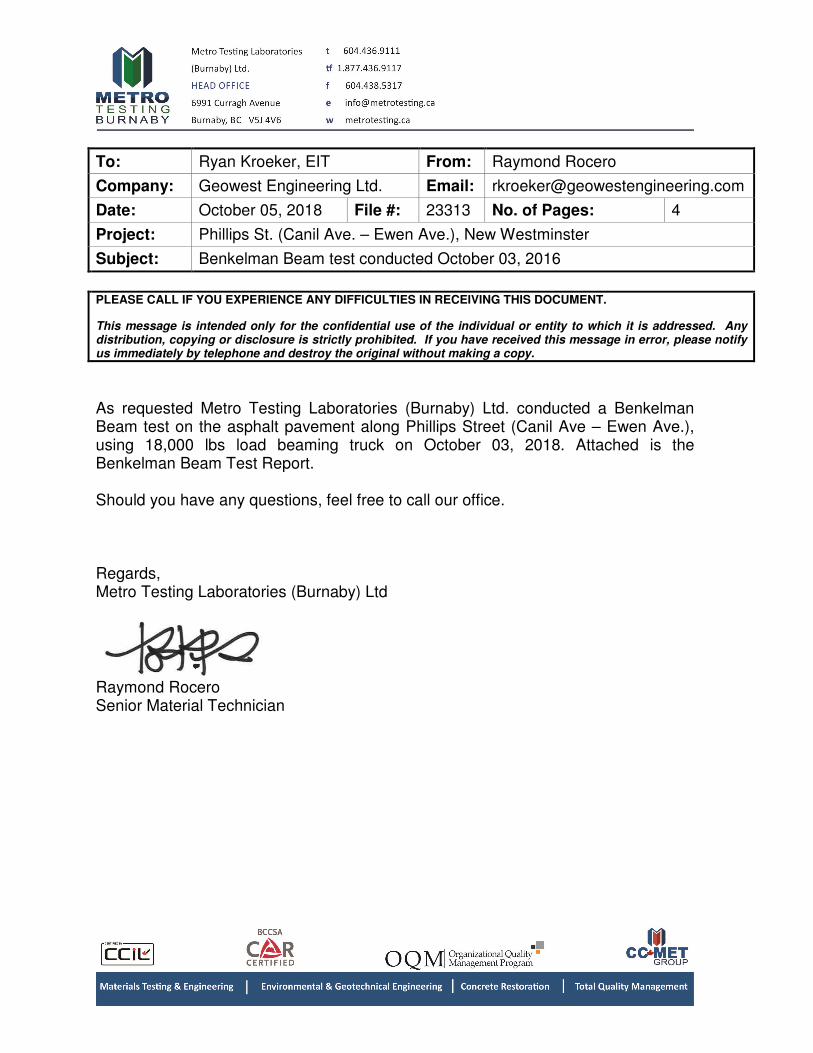
To: Ryan Kroeker, EIT From: Raymond Rocero
Company: Geowest Engineering Ltd. Email: [email protected]
Date: October 05, 2018 File #: 23313 No. of Pages: 4
Project: Phillips St. (Canil Ave. – Ewen Ave.), New Westminster
Subject: Benkelman Beam test conducted October 03, 2016
PLEASE CALL IF YOU EXPERIENCE ANY DIFFICULTIES IN RECEIVING THIS DOCUMENT.
This message is intended only for the confidential use of the individual or entity to which it is addressed. Any distribution, copying or disclosure is strictly prohibited. If you have received this message in error, please notify us immediately by telephone and destroy the original without making a copy.
As requested Metro Testing Laboratories (Burnaby) Ltd. conducted a Benkelman Beam test on the asphalt pavement along Phillips Street (Canil Ave – Ewen Ave.), using 18,000 lbs load beaming truck on October 03, 2018. Attached is the Benkelman Beam Test Report. Should you have any questions, feel free to call our office. Regards, Metro Testing Laboratories (Burnaby) Ltd
Raymond Rocero Senior Material Technician

Project: 23313
Load-Deflection (Benkelman Beam) Report
Geowest Engineering Ltd.
200 - 34425 McConnell Rd., Abbotsford
V2S 7P1
Project: Phillips St. (Canil Ave. - Ewen Ave.)
Tested on: October 03, 2018
Pavement Temperature: 10 deg C
Seasonal Correction: 1.24
FIELD CORRECTED
REBOUND REBOUND
STATION LANE (mm) (mm) COMMENT
(1) (2) (3) (4) (5)
0+0 Phillips St. North Bound 1.02 1.39
0+10 Phillips St. North Bound 1.72 2.35
0+20 Phillips St. North Bound 1.52 2.07
0+30 Phillips St. North Bound 1.14 1.55
0+40 Phillips St. North Bound 2.08 2.84
0+50 Phillips St. North Bound 1.64 2.24
0+60 Phillips St. North Bound 1.24 1.69
0+70 Phillips St. North Bound 1.94 2.65
0+80 Phillips St. North Bound 1.90 2.59
0+90 Phillips St. North Bound 2.48 3.38
1+00 Phillips St. North Bound 2.06 2.81
1+10 Phillips St. North Bound 2.14 2.92
1+20 Phillips St. North Bound 2.50 3.41
1+30 Phillips St. North Bound 2.16 2.95
1+40 Phillips St. North Bound 2.36 3.22
1+40 Phillips St. South Bound 3.36 4.58
1+30 Phillips St. South Bound 2.04 2.78
1+20 Phillips St. South Bound 2.70 3.68
1+10 Phillips St. South Bound 3.72 5.07
1+00 Phillips St. South Bound 3.78 5.16
0+90 Phillips St. South Bound 4.08 5.57
0+80 Phillips St. South Bound 3.64 4.96
0+70 Phillips St. South Bound 3.14 4.28
0+60 Phillips St. South Bound 5.08 6.93
0+50 Phillips St. South Bound 5.00 6.82
0+40 Phillips St. South Bound 5.78 7.88
0+30 Phillips St. South Bound 5.40 7.37
0+20 Phillips St. South Bound 3.28 4.47
0+10 Phillips St. South Bound 1.64 2.24
0+0 Phillips St. South Bound 1.18 1.61
Mean 3.72 mm
Standard Deviation 1.78 mm
Most Probable Spring Rebound 7.28 mm
Design Rebound 1.5 mm to be confirmed
Overlay Required - mm
Notes:
Paced distance.
Tests in every 10m.
Sta.0+00 @ Canil Ave. (see sketch)
Metro Testing Laboratories Ltd
6991 Curragh Ave.,Burnaby, BC V5J 4V6
Tel: (604) 436-9111 Fax: (604) 436-9050
MTL Phillips St., New Westminster Page 1 of 1

0.00
1.00
2.00
3.00
4.00
5.00
6.00
7.00
8.00
0+00 0+10 0+20 0+30 0+40 0+50 0+60 0+70 0+80 0+90 1+00 1+10 1+20 1+30 1+40
Reb
ou
nd
, m
m
Station, m
Geowest Engineering Ltd..Phillips St., (Canil Ave. - Ewen Ave.), New Westminster
North Bound
design rebound
South Bound