Geothermal Heat Use in Gas Processing Facilities
184
Geothermal Heat Use in Gas Processing Facilities A Feasibility Study Cameron Huddlestone-Holmes, Trevor Hadley, Ashleigh Cousins, Jenny Hayward and Chaoen Li 3 July 2015 Report Number: EP155211 Prepared for Greg Wong, Geodynamics Ltd ENERGY FLAGSHIP
Transcript of Geothermal Heat Use in Gas Processing Facilities

Geothermal Heat Use in Gas Processing Facilities A Feasibility Study
Cameron Huddlestone-Holmes, Trevor Hadley, Ashleigh Cousins, Jenny Hayward and Chaoen Li 3 July 2015
Report Number: EP155211
Prepared for Greg Wong, Geodynamics Ltd
ENERGY FLAGSHIP

Oil, Fuels and Gas Research Program CSIRO Energy
© Commonwealth Scientific and Industrial Research Organisation 2015. To the extent permitted by law, all rights are reserved and no part of this publication covered by copyright may be reproduced or copied in any form or by any means except with the written permission of CSIRO.
Important disclaimer
CSIRO advises that the information contained in this publication comprises general statements based on scientific research. The reader is advised and needs to be aware that such information may be incomplete or unable to be used in any specific situation. No reliance or actions must therefore be made on that information without seeking prior expert professional, scientific and technical advice. To the extent permitted by law, CSIRO (including its employees and consultants) excludes all liability to any person for any consequences, including but not limited to all losses, damages, costs, expenses and any other compensation, arising directly or indirectly from using this publication (in part or in whole) and any information or material contained in it.
CSIRO is committed to providing web accessible content wherever possible. If you are having difficulties with accessing this document please contact [email protected].
Geothermal Heat Use in Gas Processing Facilities | i
Foreword
This report details the results of a study of the energy use in gas processing facilities with the aim of understanding whether heat from geothermal energy resources could be incorporated into those processes. The technical and economic feasibility of this source of heat within gas processing facilities was investigated for a range of raw natural gas compositions. High-level mapping of geothermal energy and gas resources in Australia was also completed.
The project was conducted as a series of desktop studies that:
• summarised the range of raw gas compositions in gas fields in Australia and the processing requirements for these gas resources to produce pipeline grade natural gas;
• reviewed typical technologies used for gas processing in Australia and the significant energy usage and demand elements/components within gas processing plants;
• characterised the geothermal energy resources that could be combined with gas processing facilities and the costs of producing heat from these resources;
• conducted broad-based engineering calculations to demonstrate various opportunities for the integration of renewable heat sources into gas processing plants on a selection of raw gas compositions chosen for this study;
• conducted techno-economic optimisation of the use of geothermal heat sources in targeted areas of gas processing plants; and
• developed an economic framework for the assessment of the economic viability of the use of geothermal energy within gas processing plants under a range of future energy market scenarios.
Several workshops were held with Geodynamics Ltd throughout the project to promote the exchange of knowledge between CSIRO’s study and Geodynamics’ own work. An external peer reviewer was engaged to provide feedback on the approach taken within this study. The Peer reviewer also attended two of the workshops.
It is important to note that there is limited information available on the costs of developing geothermal energy resources in Australia, and no known examples of the incorporation of geothermal heat in gas processing facilities. The accuracy of modelled costs for the use of geothermal heat in gas processing facilities is therefore limited by the uncertainty that results from this lack of data. Similarly, future gas market scenarios are also uncertain. An important part of this project will be the identification of the key parameters and the sensitivity of the feasibility of this technology to this uncertainty.

ii | Geothermal Heat Use in Gas Processing Facilities
Contents
Foreword i
Acknowledgments ........................................................................................................................... xi
Executive Summary ........................................................................................................................ xii
Part I Introduction 15
1 The Opportunity ............................................................................................................... 16
2 Gas Processing Requirements .......................................................................................... 17
Part II Australia’s Natural Gas and Geothermal Energy Resources 20
3 Australia’s Geothermal Energy Resources ....................................................................... 21
3.1 Geothermal Energy Overview ............................................................................. 21
3.2 Australia’s Geothermal Energy Resource Types ................................................. 24
3.3 Geothermal Energy Use in Australia ................................................................... 26
3.3.1 Direct Use Geothermal ........................................................................................ 28
3.4 Australia’s Geothermal Energy Resources .......................................................... 28
3.5 Challenges for Geothermal Energy in Australia .................................................. 30
4 Australia’s Natural Gas Resources .................................................................................... 32
4.1 Natural Gas Sector Overview .............................................................................. 32
4.2 Australia’s Natural Gas Resources ....................................................................... 35
4.2.1 Australia’s Natural Gas Resource Types .............................................................. 36
4.3 Major Basins ........................................................................................................ 39
4.3.1 Cooper/Eromanga ............................................................................................... 41
4.3.2 Carnarvon ............................................................................................................ 42
4.3.3 Gippsland ............................................................................................................. 43
4.3.4 Otway ................................................................................................................... 44
4.3.5 Bowen/Surat CSG ................................................................................................ 45
4.3.6 Discussion ............................................................................................................ 46
5 Relationship between Australia’s Geothermal Energy and Natural Gas Resources ........ 47
Part III Natural Gas Processing 50
6 Gas Processing Plant Technology ..................................................................................... 51

Geothermal Heat Use in Gas Processing Facilities | iii
6.1 Liquid Separation ................................................................................................. 51
6.2 Contaminant Removal ......................................................................................... 52
6.2.1 Gas Sweetening (CO2 and H2S Removal) ............................................................. 52
6.2.2 Hg Removal .......................................................................................................... 55
6.2.3 Dehydration ......................................................................................................... 56
6.2.4 Nitrogen Removal ................................................................................................ 58
6.2.5 NGL Removal ....................................................................................................... 59
6.2.6 NGL Fractionation ................................................................................................ 60
6.2.7 Compression ........................................................................................................ 61
7 Major Sources of Energy Utilisation in an Australian Gas Processing Plant ..................... 62
7.1 Major Energy Requirements for an Gas Processing Plant for Pipeline Grade Gas ............................................................................................................................. 62
7.1.1 Gas Sweetening ................................................................................................... 63
7.1.2 Gas Dehydration .................................................................................................. 64
7.1.3 NGL Removal and Fractionation .......................................................................... 64
7.1.4 Compression ........................................................................................................ 64
7.1.5 Pumps .................................................................................................................. 65
7.2 Qualitative Assessment of Primary Energy Requirements in Gas Processing Facilities ............................................................................................................................ 65
8 Mass & Energy Balances and Design of Identified Major Energy Processing Steps ......... 68
8.1 Inlet Gas Conditions ............................................................................................. 68
8.2 Gas Sweetening using Aqueous Amines .............................................................. 69
8.3 Gas Dehydration using Glycol Absorption ........................................................... 73
8.4 Further Gas Processing Required ........................................................................ 74
9 Integration of Geothermal Energy in the Identified Major Energy Processing Steps ...... 76
9.1 Integration in Aqueous Amine Sweetening Step ................................................ 77
9.2 Integration in Glycol Dehydration Step ............................................................... 80
9.3 Alternative Integration in Amine Sweetening Step - Using Working Fluid ......... 81
9.4 Integration of Aqueous Amine Sweetening and Dehydration Steps .................. 84
9.5 Geothermal Brine Considerations ....................................................................... 85
9.6 Discussion ............................................................................................................ 87
10 Liquefied Natural Gas Plants ............................................................................................. 90
Part IV Economics of Geothermal Heat Use in Gas Processing Facilities 92

iv | Geothermal Heat Use in Gas Processing Facilities
11 Capital and Operating Cost Assumptions ......................................................................... 93
11.1 Geothermal Costs ................................................................................................ 93
11.2 Gas sweetening Process Costs ............................................................................. 97
11.3 Steam plant for gas-only cases .......................................................................... 101
11.4 Dehydration Plant Costs .................................................................................... 102
11.5 Total Gas Processing Plant Costs ....................................................................... 103
12 Financial Assumptions .................................................................................................... 105
12.1 Gas Prices ........................................................................................................... 105
12.2 Carbon Pricing ................................................................................................... 106
13 Methodology .................................................................................................................. 109
14 Results and Discussion .................................................................................................... 110
14.1 Levelised Cost of CO2 Removed ......................................................................... 110
14.2 Sensitivity of Levelised Cost to Assumptions .................................................... 114
14.3 Strategies for Equalising the Difference between Geothermal and Non-Geothermal Levelised Costs ........................................................................................... 119
Part V Conclusions and Future Work 125
15 Conclusions ..................................................................................................................... 126
16 Future Work .................................................................................................................... 130
17 Notation .......................................................................................................................... 132
18 References ...................................................................................................................... 134
Part VI Appendices 140
Appendix A Australian Gas Processing Plants ....................................................................... 141
Appendix B Assumptions used in the Qualitative Comparison of Gas Processing Plants for Pipeline Grade and LNG production ........................................................................................... 145
Appendix C ProTreat® Modelling of CO2 Removal from Natural Gas using Liquid Absorbents ........................................................................................................................... 147
Appendix D Modelling of Natural Gas Dehydration using Glycol ......................................... 163
Appendix E Amine Gas Sweetening Equipment Design Assumptions ................................. 169
Appendix F Gycol Gas Dehydration Equipment Design Assumptions .................................. 171
Appendix G Assumptions used for Alternative Means of Geothermal Heat Integration for the Amine Gas Sweetening Step – Using Working Fluid ................................................................... 173
Appendix H Gas-Fired Steam Boiler Assumptions ................................................................ 174
Appendix I Capital and Running Cost Assumptions ............................................................. 175

Geothermal Heat Use in Gas Processing Facilities | v
Figures Figure 1. Generalised gas processing plant flow diagram.. .......................................................... 19
Figure 2. A schematic of a geothermal system in a conductive geothermal resource................. 21
Figure 3. Temperature as a function of depth. ............................................................................. 22
Figure 4. The amount of thermal energy (Megawatts thermal = MWth) produced by a geothermal well as a function of temperature and geothermal fluid flow rate .......................... 24
Figure 5. Categorisation of Australia’s geothermal resource styles as a function of depth (approximates temperature) and the amount of enhancement required to produce the required flow rates........................................................................................................................ 26
Figure 6. The extent of the Great Artesian Basin .......................................................................... 27
Figure 7. The “Hot Baths” at Comeroo Camel Station, near Bourke, NSW .................................. 28
Figure 8. Geoscience Australia’s OzTemp interpreted temperature at 5 km depth. ................... 29
Figure 9. Australia’s natural gas production with domestic consumption and exports ............... 32
Figure 10. Australia’s gas markets, major gas producing basins, gas pipelines and processing facilities ......................................................................................................................................... 33
Figure 11. Production from Australia’s major gas producing basins ............................................ 34
Figure 12. Hydrocarbon generation is dependent on the nature of the organic matter that is buried in sediments and the pressure (depth) and temperature that that organic matter is subjected to overtime. .................................................................................................................. 37
Figure 13. A schematic showing different types of gas accumulation. ........................................ 39
Figure 14. Gas composition data for the Cooper/Eromanga Basin .............................................. 42
Figure 15: Gas composition data for the Carnarvon Basin ........................................................... 43
Figure 16. CO2 concentration in Gippsland Basin ......................................................................... 44
Figure 17. Gas composition data for the Gippsland Basin ............................................................ 44
Figure 18: Gas composition data for theOtway Basin .................................................................. 45
Figure 19. Geoscience Australia’s OzTemp map of interpreted temperatures at 5 km and Australia’s gas processing facilities and pipelines. ....................................................................... 47
Figure 20. Detailed view of key gas producing basins showing Geoscience Australia’s OzTemp map of interpreted temperatures at 5 km and gas processing facilities and gas pipelines ......... 48
Figure 21. Block flow diagram showing typical sections in a gas processing plant. ..................... 51
Figure 22. Flow diagram of a gas sweetening plant using the Benfield process .......................... 54
Figure 23. Standard amine based absorption process for removal of acid gases ........................ 55
Figure 24. Flow diagram of a typical glycol dehydration process ................................................ 57
Figure 25. Flow diagram of typical natural gas dehydration process using molecular sieves ...... 58

vi | Geothermal Heat Use in Gas Processing Facilities
Figure 26. Flow diagram of (a) single-column heat-pumped cycle, and (b) double-column heat-pumped cycle for the removal of nitrogen .................................................................................. 59
Figure 27. Diagram showing general layout of a fractionation column ...................................... 60
Figure 28. Flow diagram showing example of a fractionation train for the separation of ethane, propane and butane column ........................................................................................................ 61
Figure 29. Major energy requirements in an Australian gas processing plant, with a reference raw natural gas flow of 125 MMscfd. ........................................................................................... 63
Figure 30. Estimated normalised heat and electrical requirements for gas processing plants with low and high CO2 feed concentrations, feed with NGLs present, and LNG plants. Energy values given per kmol of CH4 produced. .................................................................................................. 66
Figure 31. Calculated reboiler duties for aqueous amine capture of CO2, showing effect of inlet CO2 concentration and stripper column pressure. ....................................................................... 71
Figure 32. Calculated reboiler duties for MDEA and PZMDEA capture of CO2, showing effect of inlet CO2 concentration and stripper column pressure. ............................................................... 71
Figure 33. Refined reboiler duties for aqueous MDEA capture of CO2, showing effect of inlet CO2 concentration and stripper column pressure. .............................................................................. 72
Figure 34. Calculated reboiler temperatures for aqueous amine capture of CO2, showing effect of inlet CO2 concentration and stripper column pressure. ........................................................... 72
Figure 35. Calculated recycle pump duties for aqueous amine capture of CO2, showing effect of inlet CO2 concentration and stripper column pressure. ............................................................... 73
Figure 36. Calculated reboiler and recycle pump duties for TEG dehydration of natural gas stream, showing effect of original CO2 inlet concentration to the sweetening step. Reboiler temperature = 200°C..................................................................................................................... 74
Figure 37. Diagram showing options for integration of geothermal energy with (a) heat used directly at source, (b) using geothermal brine to heat a separate heat fluid, and (c) geothermal brine integrated into steam generation system to preheat water prior to a boiler. ................... 76
Figure 38. Flow diagrams showing direct integration of geothermal heat for the (a) gas sweetening step, and (b) dehydration step reboilers. .................................................................. 77
Figure 39. Calculated geothermal brine flow required to supply heat to the MDEA reboiler, as a function of brine inlet temperature, CO2 concentration and stripper pressure. ......................... 78
Figure 40. Calculated MDEA reboiler surface area required when utilising geothermal brine as heat source, as a function of brine inlet temperature, CO2 concentration and stripper pressure......................................................................................................................................... 79
Figure 41. Calculated geothermal brine flow required to supply heat to the TEG reboiler and TEG reboiler surface area required, as a function of brine inlet temperature, CO2 concentration and stripper pressure. ................................................................................................................... 81
Figure 42. Flow diagram showing alternative means of integrating geothermal heat for the gas sweetening step, with the use of a working fluid. ........................................................................ 82

Geothermal Heat Use in Gas Processing Facilities | vii
Figure 43. Calculated geothermal brine flow required to supply heat to the MDEA reboiler directly (entering at 150°C) or via a working fluid (entering at 200°C), as a function of the CO2 concentration and stripper pressure. ........................................................................................... 83
Figure 44. Calculated MDEA reboiler and brine/working fluid heat exchanger surface areas required when utilising geothermal brine as heat source, via a working fluid, as a function of CO2 concentration and stripper pressure. .................................................................................... 83
Figure 45. Diagram showing possible means of integrating geothermal heat for the gas sweetening and dehydration steps, with (a) geothermal brine used to supply heat to the two steps sequentially, and (b) separate sources of geothermal heat used for the sweetening and dehydration steps. ........................................................................................................................ 84
Figure 46. Geothermal well drill cost per metre (blue) and oil price over time (pink). Note that data was not available for some years [60]. ................................................................................. 95
Figure 47. Key components used in calculating the Gas sweetening Process Capital Costs. ....... 98
Figure 48. Share each component contributes to the capital cost in a geothermal case. ......... 100
Figure 49. Share each component contributes to the capital cost in a gas-only case. .............. 101
Figure 50. Reference case projected gas prices for the EAGM derived from [73]. .................... 106
Figure 51. Carbon price scenarios. .............................................................................................. 108
Figure 52. Projected levelised cost of CO2 removed for the cases with 40% CO2 in the raw gas ............................................................................................................................................... 111
Figure 53. Projected levelised cost of CO2 removed for the cases with 21% CO2 in the raw gas ............................................................................................................................................... 111
Figure 54. Projected levelised cost of CO2 removed for the cases with 10% CO2 in the raw gas. .............................................................................................................................................. 112
Figure 55. Projected levelised cost of CO2 removed for the cases with 40% CO2 in the raw gas and under carbon price scenarios ............................................................................................... 113
Figure 56. Projected levelised cost of CO2 removed for the cases with 21% CO2 in the raw gas and under carbon price scenarios ............................................................................................... 113
Figure 57. Projected levelised cost of CO2 removed for the cases with 10% CO2 in the raw gas and under carbon price scenarios ............................................................................................... 114
Figure 58. Tornado chart of levelised cost of case 21-200-1 ...................................................... 115
Figure 59. Tornado chart of levelised cost of case 21-120-1 ...................................................... 116
Figure 60. Tornado chart of levelised cost of case 21-gas .......................................................... 117
Figure 61. Levelised costs of lowest-cost geothermal cases compared to highest-cost gas-only cases. ........................................................................................................................................... 118
Figure 62. Levelised cost of 20% cases with and without technology learning on drilling. ....... 120
Figure 63. Relationship between per well flow rate and well cost showing the influence of various carbon pricing scenarios for a feed gas with 21% CO2 ................................................... 122

viii | Geothermal Heat Use in Gas Processing Facilities
Figure 64. Relationship between per well flow rate and well cost showing the effect of geothermal resource temperature and with no-carbon price ................................................... 123
Figure 65. Relationship between per well flow rate and well cost showing the effect of geothermal resource temperature and a no carbon price scenario, a carbon price equivalent to the current Emissions Reduction Fund, and the moderate carbon price scenario (New Policy) for a feed gas with 21% CO2. ............................................................................................................ 124
Figure 66. ProTreat® models of (a) absorber, and (b) stripping column. ................................... 152
Figure 67. ProTreat® flowsheet for acid gas removal plant based on amine sweetening. ........ 153
Figure 68. ProTreat® model of glycol dehydration plant. ........................................................... 164

Geothermal Heat Use in Gas Processing Facilities | ix
Tables Table 1. Typical ranges for raw natural gas composition. Modified from literature [4]. ............. 17
Table 2. Summary of key specifications for natural gas from Australian Standard 4564 [5]. ...... 19
Table 3. Australia’s total gas resources [11]. ................................................................................ 35
Table 4. Gas reserves and production for 2014 [24]. ................................................................... 40
Table 5. Inlet raw gas concentrations used for simulations. ........................................................ 69
Table 6. Calculated gas composition and properties exiting the dehydration step. .................... 74
Table 7. Summary of key parameters for the geothermal cases used in this study. ................... 97
Table 8. Components and variables used for calculating the Gas sweetening Process Capital Costs. The materials used in costing are listed in brackets in the Variable column. CS=carbon steel and SS=stainless steel. See Figure 47 for numbering of components. ................................ 99
Table 9. Parameters related to steam generation for gas-only cases. ....................................... 101
Table 10. Details of the reboiler equipment cost and dehydration plant capital costs. ............ 102
Table 11. Direct and indirect costs as a fraction of the equipment cost associated with the gas processing plant. ......................................................................................................................... 103
Table 12. Inclusions and their assumed costs as a fraction of either Operating (OL), Fraction of Capital Investment (FCI) or Maintenance costs. ......................................................................... 104
Table 13. Financial assumptions used for calculating the levelised cost of CO2 removed. ........ 105
Table 14. Projected carbon prices from IEA scenarios in selected world regions and for various sectors ($/tCO2-e). ...................................................................................................................... 107
Table 15. Difference in levelised cost between lowest-cost geothermal and gas-only cases. A negative number indicates that geothermal has a lower levelised cost. ................................... 110
Table 16. Summary of levelised costs of lowest-cost geothermal cases. ................................... 112
Table 17. Difference in levelised cost between lowest-cost geothermal and gas-only cases under carbon price scenarios. A negative number indicates that geothermal has a lower levelised cost. ............................................................................................................................................. 114
Table 18. Combinations of gas and carbon price required to remove levelised cost differences. ................................................................................................................................. 119
Table 19. Analysis of required geothermal capital cost reduction in order to equal non-geothermal cost. A negative difference (as in the 450 ppm scenarios) means that the geothermal option costs less than the non-geothermal option without reducing the geothermal capital costs. ................................................................................................................................ 121
Table 20. Australia’s gas processing facilities, compiled from various sources. ND indicates no data published. ............................................................................................................................ 141
Table 21. Inlet natural gas conditions used for simulations. ...................................................... 148
Table 22. Standard concentration ranges for solvents, and concentration used in simulation. 150

x | Geothermal Heat Use in Gas Processing Facilities
Table 23. Recommended maximum lean and rich CO2 loading ranges for solvents. ................. 150
Table 24. Maximum lean and rich CO2 loadings used in this study. ........................................... 150
Table 25. Effect of packing type on CO2 capture, column diameter and pressure drop in absorber. ..................................................................................................................................... 152
Table 26. Overview of modelling results achieved using MDEA as solvent for CO2 removal from gas stream containing low hydrocarbons. .................................................................................. 155
Table 27. Overview of modelling results achieved using MDEA as solvent for 10% and 21% CO2 removal with random packing, and gas stream containing higher hydrocarbon content. ........ 156
Table 28. Overview of modelling results achieved using MDEA as solvent for 40% CO2 removal with random packing from gas stream containing higher hydrocarbon content. Cooler temperatures of 40 and 50°C. ..................................................................................................... 157
Table 29. Overview of modelling results achieved using PZMDEA as solvent for CO2 removal from gas stream containing higher hydrocarbon content. ......................................................... 158
Table 30. Overview of modelling results achieved using DEA as solvent for CO2 removal from gas stream containing higher hydrocarbon content. ........................................................................ 159
Table 31. Overview of modelling results using 30 wt% MEA to treat gas stream containing 21 % CO2 and higher hydrocarbon content. ........................................................................................ 160
Table 32. Overview of TEG dehydration system results. ............................................................ 166
Table 33. Effect of altering stripper pressure on TEG regeneration temperature. .................... 167
Table 34. Effect of altering stripper pressure on temperature of DEG regeneration. ............... 167
Table 35. Characteristics of cases examined. ............................................................................. 175
Table 36. Geothermal capital cost components and total geothermal capital cost including 18.5% contingency and project management, per project. The total cost also includes the costs of exploration, well head and brine reticulation systems and reservoir stimulation. The operating cost is also shown. ...................................................................................................... 176
Table 37. Details of the reboiler costing and the total gas sweetening plant capital costs ........... 1
Table 38. Summary of costs assumed per case. ............................................................................. 2

Geothermal Heat Use in Gas Processing Facilities | xi
Acknowledgments
This project was co-funded by Geodynamics Ltd and CSIRO. We would like to thank Greg Wong and Ben Humphries from Geodynamics Ltd for many valuable discussions throughout the life of this project.
The Australian Renewable Energy Agency is acknowledged for their role in suggesting that this study be conducted.
We would also like to thank Dr Trina Dreher (SUEZ Environnement Oil & Gas Systems, formally Process Group), who acted as a peer reviewer for this study. Dr Dreher was able to provide very useful insight into the practical considerations for the design of gas processing facilities.
Dr Nick Burke and Aaron Cottrell from CSIRO provided thorough reviews of this report.
Dr Liam Wagner, Lecturer in Economics at Griffith University, provided assistance with gas price forecasts.
In acknowledging the input of others, we acknowledge that the work presented here is that of the authors and any errors or omissions are ours.

xii | Geothermal Heat Use in Gas Processing Facilities
Executive Summary
Natural gas is an important resource for Australia, both as a domestic energy resource and as an export commodity. Exports of LNG are forecast to increase by four to five times from current levels by the end of the decade, with Australia expected to become the world’s largest exporter of LNG. Export revenue is forecast to exceed $50 billion per annum. Australia’s gas sector consumes approximately 8 to 10% of the gas produced – the equivalent of the output of one large LNG facility – for the processing of gas. If this energy for processing could be sourced from alternatives to gas, then additional supply for domestic consumption and export would be available.
The scope of work in this study is presented in the foreword to this report. This study has attempted to understand the feasibility of using geothermal heat in gas processing plants to offset the use of potential sales gas within those facilities. The use of geothermal energy to provide energy for process heat could be desirable if it reduces costs, increases the amount of gas available for sale, or helps to mitigate a future carbon price. Using geothermal energy in direct use applications may provide a more effective use of this resource as it avoids the relatively low conversion efficiencies associated with converting the low grade heat in geothermal resources in to electricity.
Natural Gas and Geothermal Resources
A desktop study was conducted using available data of Australia’s natural gas and geothermal resources. Australia has large conventional gas and coal seam gas resources that are reasonably well defined along with significant potential for unconventional gas resources that have not been as well tested. The specifications for gas to be sold to domestic markets or used for LNG production for export are well understood and reasonably consistent. However, the composition of raw gas in situ in Australia is highly variable at basin scale. It is difficult to obtain data on the raw gas compositions produced from the various basins in Australia or the feed gas composition of existing gas processing facilities. While gas analyses conducted during exploration have to be reported, production test data and detailed gas analysis does not. This information is considered commercially sensitive and is rarely published.
While some basins show higher degrees of maturity than others, all basins have gas accumulations that have high concentrations of impurities such as CO2, H2S and N2 that will need to be removed if that gas is to be brought to market. Processing to separate NGL’s and condensate from gas will also be required in many instances, and dehydration is a ubiquitous requirement. LNG plants have lower tolerance to water, CO2 and condensing hydrocarbon content as these components would cause problems during the liquefaction processes.
Australia’s geothermal resources are not as well defined as its gas resources. While the temperature distribution is reasonably well understood in the basins that have seen significant amounts of oil and gas exploration, information on permeability at depth, or the existence of conditions favourable to the enhancement of permeability, is not readily available. The highest geothermal gradients seen in Australia are in the Nappamerri Trough in the Cooper Basin. This heat resource is the target of Geodynamics Ltd’s Innamincka Deeps Project. Elevated geothermal gradients are also observed in
Geothermal Heat Use in Gas Processing Facilities | xiii
most of Australia’s other hydrocarbon producing basins including the Gippsland, Otway, North Perth and onshore Carnarvon Basin. Locally elevated thermal gradients are also observed in the Surat Basin.
Within each sedimentary basin, there are local heat anomalies that result from heterogeneities in the geology at the kilometre to tens of kilometre scale. Detailed exploration would be required to identify the most prospective geothermal targets. Data collected as part of exploration for oil and gas could be used if added emphasis was placed on collecting appropriate data (temperature logs, thermal conductivities, geomechanical properties). New build gas processing facilities could be located on or near these resources as it is easier to move gas to a processing plant than heat to a gas plant.
Australia’s geothermal resources are relatively unproven. This study has assumed flow rates of 100 kg/s for natural reservoirs and 80 kg/s for EGS resources. These flow rates are yet to be demonstrated in Australia. This highlights one of the key challenges for geothermal heat utilisation for industrial process heat in Australia, and that is demonstrating that the required flow rates can be achieved, and reducing the risks in discovering geothermal resources.
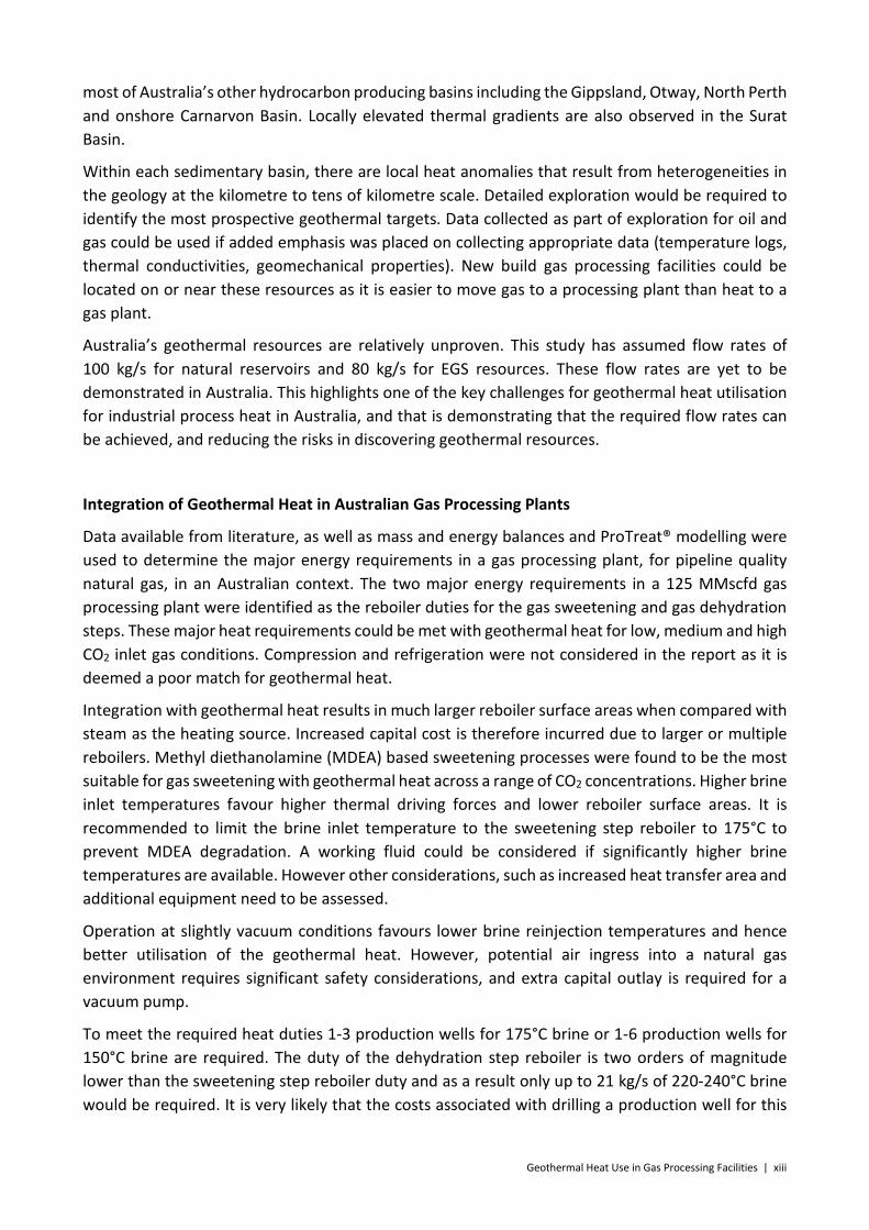
Integration of Geothermal Heat in Australian Gas Processing Plants
Data available from literature, as well as mass and energy balances and ProTreat® modelling were used to determine the major energy requirements in a gas processing plant, for pipeline quality natural gas, in an Australian context. The two major energy requirements in a 125 MMscfd gas processing plant were identified as the reboiler duties for the gas sweetening and gas dehydration steps. These major heat requirements could be met with geothermal heat for low, medium and high CO2 inlet gas conditions. Compression and refrigeration were not considered in the report as it is deemed a poor match for geothermal heat.
Integration with geothermal heat results in much larger reboiler surface areas when compared with steam as the heating source. Increased capital cost is therefore incurred due to larger or multiple reboilers. Methyl diethanolamine (MDEA) based sweetening processes were found to be the most suitable for gas sweetening with geothermal heat across a range of CO2 concentrations. Higher brine inlet temperatures favour higher thermal driving forces and lower reboiler surface areas. It is recommended to limit the brine inlet temperature to the sweetening step reboiler to 175°C to prevent MDEA degradation. A working fluid could be considered if significantly higher brine temperatures are available. However other considerations, such as increased heat transfer area and additional equipment need to be assessed.
Operation at slightly vacuum conditions favours lower brine reinjection temperatures and hence better utilisation of the geothermal heat. However, potential air ingress into a natural gas environment requires significant safety considerations, and extra capital outlay is required for a vacuum pump.
To meet the required heat duties 1-3 production wells for 175°C brine or 1-6 production wells for 150°C brine are required. The duty of the dehydration step reboiler is two orders of magnitude lower than the sweetening step reboiler duty and as a result only up to 21 kg/s of 220-240°C brine would be required. It is very likely that the costs associated with drilling a production well for this

xiv | Geothermal Heat Use in Gas Processing Facilities
supply would far outweigh the advantages of replacing the steam to the gas dehydration reboiler with geothermal heat.
In an Australian context, based on the raw natural gas assumptions in this report and in the absence of a techno-economic analysis, utilising geothermal heat for the gas dehydration step is not warranted, unless a source of high temperature brine already exists. In this scenario, it is suggested that a separate supply of geothermal brine, at the required temperature is utilised for the gas sweetening and gas dehydration reboilers.
In an Australian context, geothermal heat is best matched with the gas sweetening step, as the high reboiler duties allow for a good match with flow rates anticipated from geothermal resources. The largest geothermal brine flows are required for CO2 inlet gas concentrations of 40%. At this high inlet concentration it is estimated that energy savings of up to 5% of the sales natural gas can be made. However, compromises may need to be made between operating cost savings and the increased capital cost required when integrating geothermal heat.
Economic Evaluation
An economic evaluation was made of the 125 MMscfd gas processing plant. A comparison of the economics of utilising geothermal heat in gas processing plants against the use of gas to supply heat found that the costs are comparable within the level of accuracy of this study. This finding indicates that the use of geothermal heat in a processing plant warrants more detailed consideration on a case-by-case basis. A higher gas price or the introduction of a carbon price would further enhance the economics of the geothermal option.
The CO2 removed in the sweetening step is in a concentrated form making it a good candidate for sequestration. If integration with geothermal heat required a high carbon price to be attractive, then CO2 sequestration may also be attractive to reduce the overall carbon price liability.
The economic results were found to be most sensitive to geothermal capital costs, gas fuel costs and gas processing plant operating costs. There is a great deal of uncertainty around geothermal field costs and well flow rates. To deal with this uncertainty, we have considered what the geothermal field costs would have to be to allow the geothermal option to be competitive with the base case (non-geothermal) for a range of resource temperatures.
Final Comments
This study has found that the use of geothermal energy in the gas sweetening step is technically feasible in an Australian context and that integrating geothermal heat directly at the reboiler can readily be done, unless there are concerns for scaling or corrosion. For the cases investigated, geothermal heat is well matched to supply the heat duty in the gas sweetening step, particularly in scenarios allowing lower reboiler operating temperatures and natural gas streams with high CO2 concentration. The integration with geothermal heat would reduce the self-consumption of gas if no other heat source is available. No major above ground technical barriers are envisaged, and integration would be determined based the economics and the below-ground challenges. The economic evaluation results show that integration of geothermal heat is competitive with the gas-only options, but only with geothermal resources at the higher end of the temperature scale.

Geothermal Heat Use in Gas Processing Facilities | 15
Part I Introduction

16 | Geothermal Heat Use in Gas Processing Facilities
1 The Opportunity
Natural gas is an important energy source globally, supplying approximately 21% of the world’s primary energy demand in 2012 [1]. The natural gas industry in Australia is also growing rapidly with a doubling of production since the turn-of-the-century to approximately 2,000 MMscf per year in 2014.
Natural gas is formed from organic manner, such as plants, algae and zooplankton, which have been buried in sediments. The composition of natural gas resources is highly dependent on the nature of the organic matter from which it is derived and the burial history (pressure, temperature and time) of the sediments that they are buried in. Most natural gas resources are predominantly methane, but can have significant quantities of longer chain hydrocarbons, other gases such as carbon dioxide and nitrogen, and water. This raw gas needs to be processed to provide a product with consistent properties before it can be used as a fuel. Hydrocarbons other than methane are usually extracted for higher value uses such as fuel (e.g. propane and butane for liquefied petroleum gas, or LPG) or as a feedstock for petrochemicals (e.g. ethane which is used to make ethylene).
Processing of natural gas can require significant amounts of energy in the form of heating, cooling, pumping and compression (see Section 6 for a detailed description of gas processing). These energy requirements are typically met through the consumption of some of the gas produced within the plant. 8% of gas production at the Moomba gas processing facilities is used to provide energy (heat as steam and electricity) within the facilities [2]. Gas is burned to produce heat (usually in the form of steam), to produce electricity (typically in combined heat and power systems) and for compression (gas turbine driven compressors). The amount of energy used in each form will be very much dependent on the composition of the raw gas entering the processing plant, the composition of the produced gas, and the choice of processes within the plant. The consumption of gas within the plant reduces the quantity of saleable gas produced, reducing revenue, and contributes to the CO2 emissions of the plant.
Geothermal energy in the form of heat and/or power could be used within gas processing facilities to reduce the amount of feed gas consumed. A preliminary study of the potential applications of geothermal energy in hydrocarbon fields conducted for the Australian Renewable Energy Agency’s International Geothermal Expert Group [3] found that heat from geothermal energy had a good probability of becoming a commercially viable replacement to heat produced from burning gas in the Cooper Basin region between 2020 and 2030.
The Evans & Peck (2014) assessment was made on the basis of the cost of supplying geothermal energy to various processes and did not consider CO2 emissions costs in any detail. Reducing the CO2 emissions and increasing the available volume of gas for sales may provide an additional driver for considering geothermal heat in gas processing plants.

Geothermal Heat Use in Gas Processing Facilities | 17
2 Gas Processing Requirements
Natural gas resources contain hydrocarbons, water vapour and a range of contaminants. The hydrocarbon component of raw natural gas is predominantly methane (CH4) but also includes other low molecular weight hydrocarbons including ethane (C2H6), butane (C3H8), and propane (C4H10) and their isomers. These hydrocarbons are in the gas phase at standard atmospheric conditions. Raw gas at reservoir conditions (typically higher pressures and temperatures than atmospheric) may contain longer chain hydrocarbons in the gas phase which condense once at the surface and these compounds are referred to as natural gas condensates (or simply ‘condensates’). Raw gas at reservoir conditions is typically saturated with water and when the gas is brought to the surface, its ability to carry water will be reduced because of the reduced temperatures and pressures and some of that water will condense (the raw gas will still be saturated with water). Some of the other impurities include carbon dioxide (CO2), nitrogen (N2), hydrogen sulphide (H2S), helium (He), and mercaptans (organic sulphur compounds). Table 1 shows some of the typical ranges of raw gas compositions. It is important to note that actual gas compositions are infinitely variable with some gas accumulations containing methane and water vapour only, such as in the case of the majority of coal seam gas resources currently being developed in Queensland, and others containing over 90% CO2, as found in the Caroline-11 well in South Australia.
Table 1. Typical ranges for raw natural gas composition. Modified from literature2 [4].
Methane CH4 60-90% Ethane C2H6
0-20% Propane C3H8 Butane C4H10 Pentane C5H12 Carbon Dioxide CO2 0-30% Oxygen O2 0-0.2% Nitrogen N2 0-5% Hydrogen Sulphide H2S <1% Other Rare gases trace Water# H2O ~103 to 104 mg/m3
#The water content of the gas at surface will be strongly dependent on the pressure and temperature of the gas. The range of water content given here assumes temperatures and pressures typically found at the point where gas arrives at the surface (separator).
Natural gas as a product used by consumers is predominantly methane. The raw natural gas must be processed to remove impurities and also to remove hydrocarbons of higher value (as further discussed in Section 6). For example, Liquefied Petroleum Gas (LPG) is predominantly propane and butane, and sells at a premium over natural gas. Natural gas is typically
1 The gas produced from the Caroline-1 well provides CO2 for industrial purposes, and is not a ‘natural gas’ resource per se.
2 http://naturalgas.org/overview/background/ (accessed 23/4/2015)

18 | Geothermal Heat Use in Gas Processing Facilities
distributed via pipelines and the gas delivered to pipelines must have a consistent specification so that it can be safely transported (via pipelines) and used efficiently by consumers. Australian Standard 4564 [5] “sets out requirements for the safe composition, transportation and supply of general purpose natural gas for use in natural gas appliances and equipment, and for use as fuel in natural gas vehicles” provides a useful reference for pipeline grade natural gas. The standard defines the composition of natural gas in terms of its energy content (maximum and minimum), allowable content of non-combustible gases and other contaminants, water content, and hydrocarbon dew point (Table 2). The specifications ensure that the gas can be safely transported by pipeline without causing corrosion or forming liquid phases, and that the gas burns in a consistent and safe way in appliances without any harmful or toxic by-products (aside from those normally produced by the combustion of natural gas). The energy content is measured via the Wobbe Index, which allows the burning characteristics of different composition gases to be compared and is often referred to as a measure of interchangeability.
The vast majority of natural gas used in Australia either complies with this standard or is at a specification that is close to this standard. Exceptions exist where a gas processing facility supplies an end user directly. For example, the 80 MW Ladbroke Grove Power Station was designed to use the natural gas with high CO2 concentrations that were delivered from the Ladbrook Grove field and processed by the adjacent Katnook processing plant3. Gas production from this field ceased in 2006 and the power plant is now fuelled from pipeline gas originating in Victoria4.
The specifications for Liquefied Natural Gas require lower concentrations of CO2 (typically less than 50 ppm [6]) and water (typically less than 1 ppm [7], [8]) as these impurities freeze in the cryogenic processes used to liquefy the gas. Similarly, the amounts of butane and heavier hydrocarbons are also limited as they may also freeze during this process. Other specifications for LNG will depend on the market that the product is being supplied to.
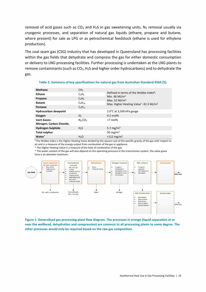
The processing requirements for a particular gas resource are determined by the composition of gas within that resource. The high degree of variability of raw gas compositions from resource to resource means there is a high degree of variability in the detailed design of gas processing plants. However, there is a basic process flow that most gas processing plants follow and this is presented in Figure 1. These processes are discussed in more detail in Section 6. All gas processing plants will have some kind of liquid separator to capture the liquids (water and hydrocarbons) that condense as the gas temperature and pressure drops as it is brought to the surface. Further dehydration will invariably be required to lower the water content to a point suitable for transport in pipelines, and compression will be required to drive the gas through pipelines. Other steps, in the process will only be used if the gas composition and the specification for the processed natural gas require it. These steps include
3 http://www.petroleum.dmitre.sa.gov.au/__data/assets/pdf_file/0019/27307/pgsa1_v2_chapter_4.pdf
4 http://www.misa.net.au/__data/assets/pdf_file/0011/34112/prospectivity_otway.pdf
Geothermal Heat Use in Gas Processing Facilities | 19
removal of acid gases such as CO2 and H2S in gas sweetening units, N2 removal usually via cryogenic processes, and separation of natural gas liquids (ethane, propane and butane, where present) for sale as LPG or as petrochemical feedstock (ethane is used for ethylene production).
The coal seam gas (CSG) industry that has developed in Queensland has processing facilities within the gas fields that dehydrate and compress the gas for either domestic consumption or delivery to LNG processing facilities. Further processing is undertaken at the LNG plants to remove contaminants (such as CO2, H2S and higher order hydrocarbons) and to dehydrate the gas.
Table 2. Summary of key specifications for natural gas from Australian Standard 4564 [5].
Methane CH4 Defined in terms of the Wobbe Index#: Min. 46 MJ/m3 Max. 52 MJ/m3 Max. Higher Heating Value^: 42.3 MJ/m3
Ethane C2H6 Propane C3H8 Butane C4H10 Pentane C5H12 Hydrocarbon dewpoint 2.0°C at 3,500 kPa gauge Oxygen O2 0.2 mol% Inert Gases: Nitrogen, Carbon Dioxide,
N2,CO2 <7 mol%
Hydrogen Sulphide H2S 5.7 mg/m3 Total sulphur 50 mg/m3 Water* H2O <112 mg/m3
# The Wobbe Index is the Higher Heating Value divided by the square root of the specific gravity of the gas with respect to air and is a measure of the energy output from combustion of the gas in appliance. ^ The Higher Heating Value is a measure of the heat of combustion of the gas. * The water content of the gas will also depend on the operating pressure in the transmission system, the value given here is an absolute maximum.
Figure 1. Generalised gas processing plant flow diagram. The processes in orange (liquid separation at or near the wellhead, dehydration and compression) are common to all processing plants to some degree. The other processes would only be required based on the raw gas composition.

20 | Geothermal Heat Use in Gas Processing Facilities
Part II Australia’s Natural Gas and Geothermal Energy Resources

Geothermal Heat Use in Gas Processing Facilities | 21
3 Australia’s Geothermal Energy Resources
3.1 Geothermal Energy Overview
Geothermal energy is simply heat from the earth. While there is a good deal of variety in geothermal energy systems all have three basic components. The first is the geothermal resource (the heat), the second is the method with which this heat is accessed, and the third is the component that uses the heat.
Figure 2 shows a geothermal system that illustrates these three components. The primary aspect of a geothermal resource is heat. In this case, the heat in the resource comes from deep within the earth and has been trapped by insulating rocks that overlie the resource. Another important characteristic of geothermal resources is the presence of fluid such as water or steam that can easily flow through the rock. In this case the fluid exists in fractures in the rock. These fractures could be naturally occurring or engineered through reservoir stimulation. The fluid may be naturally occurring or introduced to the system
The heat energy in geothermal resources is accessed through wells drilled into the resource. The heat is then brought to the surface in a fluid (water or steam) through production wells. In the example shown here, the fluid is circulated in a loop comprising of a pair of wells. Cool water is injected into the resource through one well. This water travels through the reservoir where it is heated before it is produced from the resource through the second well, bringing heat to the surface.
Once the heat has been brought to the surface in this hot fluid, the heat can be put to work. This can be through a power
Figure 2. A schematic of a geothermal system in a conductive geothermal resource.

22 | Geothermal Heat Use in Gas Processing Facilities
station, as shown in this example, or the heat can be used in direct use applications such as district heating or industrial processes. Applications for direct use of geothermal heat in gas processing could include: use in a central boiler for the provision of low pressure steam; preheating for high pressure steam; in turbines to drive compressors; in reboilers to supply the duty requirement.
Temperatures increase with depth in almost all geological settings. However, the rate at which temperature increases with depth is highly variable and dependent on a range of geological factors. The majority of the geothermal resources currently exploited for power generation are convective hydrothermal systems (where the heat is carried upwards by fluids, Figure 3) that are found in regions associated with tectonic plate boundaries and volcanic areas (e.g. west coast of the USA, New Zealand, Indonesia, Iceland, Italy and Japan), and extensional to transtentional tectonic settings (e.g. Basin and Range province, western USA). These systems have high temperatures at shallow depths (<3,000 m), due to high heat flows caused by hot fluids moving upwards through rocks with high natural permeability. This permeability is usually within sub-vertical faults and fractures caused by active tectonic processes with flow concentrated in these fractured zones. These conventional, convection dominated, geothermal resources are restricted to geological settings that are in regions of active tectonics along plate boundaries.
Globally, there is growing activity in developing geothermal resources outside of these geological settings to increase the uptake of geothermal energy. These geothermal resources are dominated by conductive heat flow (Figure 3) and are often described as ‘unconventional’ because of their differences to those geothermal resources that have been developed. Conductive heat flow occurs when heat moves without the movement of the material or fluids within that material (heat moving through a metal rod for example), and is less efficient than convective heat flow. As a result, these resources tend to have lower thermal gradients than convection dominated resources, requiring deeper drilling to reach high enough resource temperatures. Australia’s geothermal resources are predominantly conductive.
Thermal gradients (dT/dZ) in conductive regimes are related to crustal heat flow (Q) and thermal conductivity (λ) via the following equation:
Temperature
Dep
th
Temperature
Dep
th
ConvectiveHeat Transport
Conduction
Figure 3. Temperature as a function of depth for a conduction dominated regime (left) and convection dominated regime on the right. After Sanyal and Butler [85].

Geothermal Heat Use in Gas Processing Facilities | 23
𝑑𝑑𝑑𝑑𝑑𝑑𝑑𝑑
= −𝑄𝑄λ
The average thermal gradient for the continents is around 25 to 30°C/km [9], indicating that the average crustal temperature at 5,000 m depth will be around 150°C. Higher temperatures could be found by drilling deeper or by targeting areas with higher than average thermal gradients. Anomalous thermal gradients in conductive thermal regimes are found where crustal heat flow (Q) is above average (due to mantle heat flow variations or heat production within the crust), thermal conductivity (λ) is below average, or a combination of these factors. Heat flow has two components, mantle derived heat flow and heat generated in the crust (the outer 25 to 70 km layer of the Earth). Mantle heat flow is relatively uniform although it may be higher in areas where the crust is thinner, above mantle hot spots, or where mantle degassing carries heat in to the lower crust. The primary mechanism of heat generation in the crust is through the decay of the radioactive isotopes of potassium, uranium and thorium. The heterogeneous distribution of these elements creates significant variations in the heat generated in the crust. These elements are often found in relatively high abundances in some granitic rocks and these rocks are often targeted for geothermal energy development.
The thermal conductivity of rock depends on its composition and structure (grain size, presence of pore space or fractures). Organic rich sedimentary rocks such as mudstone, shale and coal typically have lower than average thermal conductivities whereas rocks like granite, sandstone and gneiss have relatively high thermal conductivities. Areas that have high amounts of rock with low thermal conductivity (e.g. coal rich sedimentary basins) will tend to have high thermal gradients because of the insulating properties of these sediments.
Fluid flow is also very important for geothermal energy resources. Beneficial use of geothermal heat can only be achieved by bringing the heat to the surface in a fluid (steam or water). This fluid may occur naturally in the subsurface reservoir or it may have to be introduced into the system. High flow rates require wells to either intersect formations that have high natural permeability (a measure of the ability of fluid to flow through the rock) or for the existing permeability to be increased. In convective geothermal resources this fluid is present by definition as is the permeability, usually in the form of open fractures. In conductive geothermal setting, as found in Australia, the permeability and fluid may be present in fractures or primary porosity/permeability (the fluid flows within interconnected space, or pores, between sedimentary grains). Alternatively, there may by not be sufficient volumes of fluid in the rock and the fluid pathways may not exist. In this case these reservoirs would need to be enhanced or engineered, usually through the injection of water at high pressure (reservoir stimulation) to open existing fractures or to create new fractures.
The amount of energy that can be extracted from an individual geothermal well will be dependent on the temperature of the resource and the available flow rate. This concept is demonstrated in Figure 4 which shows the amount of thermal energy available as a function of the flow rate and the temperature of the resource. By comparison, burning natural gas at a rate of one cubic metre per second would produce approximately 38 MWth.

24 | Geothermal Heat Use in Gas Processing Facilities
Figure 4. The amount of thermal energy (Megawatts thermal = MWth) produced by a geothermal well as a function of temperature and geothermal fluid flow rate (assuming an ambient temperature of 20°C and pure water).
For a geothermal energy resource to be viable then the amount of energy produced per well needs to be high enough to account for the cost of the well and associated plant. While drilling deeper may result in accessing higher temperatures, permeability (and therefore flow rates) may be lower and the total energy produced may not be as high as desired. Drilling deeper will also increase drilling costs. The development of geothermal resources will require achieving a balance between temperature, flow rate and the cost of accessing the resource.
3.2 Australia’s Geothermal Energy Resource Types
The Australian continent lies entirely within the Indo-Australian tectonic plate, As a result of this tectonic setting, the generally compressive stress regime in Australia [10] and low levels of tectonic activity, Australia does not have the convective heat flow regimes that typify the majority of geothermal provinces worldwide. The Australian continent’s thermal structure is dominated by conductive processes and the geothermal resources in Australia are generally considered to fall in the conductive category.
Australia’s geothermal resources have often been categorised as either Hot Sedimentary Aquifers (HSA) or Enhanced (or Engineered) Geothermal Systems (EGS). HSA resources could be considered as one end member in a continuum, representing resources that have high natural permeability. EGS resources then cover a broad spectrum with increasing amounts of reservoir enhancement required up to a point where reservoirs have no natural permeability. The three resource categories shown in Figure 5 provide useful distinctions for describing the fundamental aspects of different geothermal resource types in Australia.
Thermal Energy
Flow Rate (kg/s)
20 40 60 80 100 120 140 160
Res
ourc
e Te
mpe
ratu
re °C
50
100
150
200
250 180 MWth160 MW
th140 MW
th120 MWth
100 MWth80 MW
th60 MWth
40 MWth20 M
Wth

Geothermal Heat Use in Gas Processing Facilities | 25
A. Shallow, direct use: Typically in the 500 m to 1,500 m depth range targeting aquifers with high permeabilities at low to moderate temperatures for direct use applications. Geothermally heated swimming pools in Perth are an example. The geothermal resource that provides heat for the geothermal power station at Birdsville in Queensland also fits in to this category, even though it is not a direct use application.
B. Deep, natural reservoir: Typically greater than 1,500 m targeting aquifers with high permeabilities (no or minimal stimulation required) for direct use or electricity generation. These resources are in sedimentary aquifers (the fluid is stored within the space between sedimentary grains), fractured aquifers (the fluid is stored and flows within fractures in the rock) or some combination of the two.
C. Enhanced Geothermal Systems: Geothermal resources where the reservoir needs to have its permeability increased via the stimulation of existing structures or the creation of new ones. Heat may be used for direct use or electricity generation, although electricity generation is the main target. An example of this resource type is Geodynamics Limited’s Innamincka Deeps project in the Cooper Basin.
Figure 5 also shows a schematic of the variety of geological settings for the three resource types described above. The primary difference between types A and B is the depth of the resource, with the shallower type A resources having lower temperatures, lower drilling costs and lower resource characterisation costs. The direct use applications that these shallow resources are used for (swimming pool heating, space heating) do not require very high temperatures but do require good flow rates.
A common factor of all of these resource types is the importance of sedimentary basins. Type A and B resources, in most cases, rely on the aquifers found within basins. All three resource types benefit from the fact that in many cases basins have rocks (coal, carbonaceous mudstones and shales) with low thermal conductivities that trap heat, increasing the thermal gradient. Over 60% of the Australian continent is covered by sedimentary basins.
When these basins are over basement rocks with average or above average heat flow, anomalously high thermal gradients result. For example, heat generated in the Big Lake Suite Granodiorite is trapped by the insulating carbonaceous mudstones, siltstones and coals of the overlying Cooper and Eromanga Basins at Geodynamics’ geothermal development near Innamincka in South Australia. Anomalously high heat flows from lower in the crust may also contribute to this resource. Here, the thermal gradient exceeds 50°C/km and the heat flow exceeds 100 mW/m2 nearly double the average for continental crust (25–30°C/km and 65 mW/m2). High heat producing basement rocks are thought to be widespread within Australia [11].

26 | Geothermal Heat Use in Gas Processing Facilities
3.3 Geothermal Energy Use in Australia
There have been three distinct phases in the development of the Australian geothermal sector. Before the mid-90s, there was limited activity primarily focussed on direct use applications of hot groundwater. From the mid-90s, geothermal energy received a significant boost in interest with a focus on power generation, with a peak of activity around 2010. More
Effort to increase permeability(hydraulic fracturing or other form of stimulation)
Dep
th (~
Tem
pera
ture
)
A
C
B
Type B
Type A
150 C
200 C
Sandstone
Shale
Insulating coaland mudstone
Sandstone
Type B or C
Type B or C
Type C Type C Shale
No resource, no insulating layers
to trap heat
100m
2000m
4000m
Figure 5. Categorisation of Australia’s geothermal resource styles as a function of depth (approximates temperature) and the amount of enhancement required to produce the required flow rates. A) shallow, direct use; B) deep, natural reservoirs; and C) Enhanced Geothermal Systems and hypothetical geological settings for geothermal resources in Australia.

Geothermal Heat Use in Gas Processing Facilities | 27
recently the geothermal sector has undergone a significant decline in activity with little activity in Australia in 2015 [12].
Prior to the 1990s, there had been several localities with limited tourist development around natural springs including Tallaroo and Innot (Queensland), Daley River (Northern Territory), Hastings (Tasmania), Tumut (New South Wales) and in Perth (Western Australia), district heating in Portland, Victoria, and process water for paper manufacturing, in Taralgon, Victoria [13].
Australia’s first two geothermal power plants were developed in Mulka, South Australia in 1986 and in Birdsville, Queensland in 1992. Mulka only produced 20 kW and ran for three years. The Birdsville plant has been running intermittently since commissioning with several upgrades. Current output is approximately 80 kWe net with a capacity factor of over 95%, supplying just under a third of Birdsville’s electricity needs
Following these early efforts, there was a rapid uptake in geothermal energy activity primarily
driven by the private sector during the 2000’s, with the peak of activity coming in 2010, with over 414 exploration licences or licence applications held by over 50 entities covering approximately 472,000 km2 across all Australian states and the Northern Territory [13]. During this period the industry was focussed on developing resources suitable for electricity generation, targeting reservoir temperatures over 150°C, with only a few exceptions. There have been four projects that have drilled to reservoir depths in Australia: Geodynamics Limited’s Innamincka Deeps Project; Petratherm’s Paralana Project, Origin Energy Limited’s Innamincka Shallows Project and Panax Limited’s Penola Project. The first two are targeting EGS (Type C) resources while the second two were targeting natural reservoirs (Type B). Only the Innamincka Deeps Project with six wells has progressed beyond a single well. In all cases, the temperatures found were close to expectations. The flow rates, however, have been lower than expected, particularly for the natural reservoirs. These projects are described in more detail in [13].
Figure 6. The extent of the Great Artesian Basin (beige) showing recharge areas (dark yellow), flow direction (green arrows) and clusters of springs (red dashed outline). Source: http://wetlandinfo.ehp.qld.gov.au/wetlands/ecology/aquatic-ecosystems-natural/groundwater-dependent/unweathe

28 | Geothermal Heat Use in Gas Processing Facilities
3.3.1 Direct Use Geothermal
There has been a long history of the exploitation of geothermal resources for direct use application, with direct use application, as briefly mentioned above. There are many examples of the hot artesian waters in the Great Artesian Basin being used for tourism. In nearly all cases, hot water accessed in water bores drilled for drinking water are used, with varying levels of sophistication (Figure 7). There are some localities where natural hot springs occur in the Great Artesian Basin (Dalhousie Hot Spring in South Australia for example), and these are popular tourist attractions.
There are two fish farms that use warm groundwater for aquaculture, producing barramundi, a tropical fish, in Victoria and South Australia. A meat processing plant in Victoria, owned by the Midfield Group, uses 42°C groundwater from an 800 m deep bore as feedwater for sterilisation (82°C) and hand washing water (40°C). Significant energy savings are achieved by using the groundwater, which is 30°C hotter than the town water supply used previously.
There are two geothermal spas in Victoria – Quality Suites Deep Blue (which includes a resort) in Warrnambool and Peninsula Hot Springs at Rye on the Mornington Peninsula. These two spas draw
water from aquifers approximately 700 m deep at temperatures in around 43°C [12].
There are 11 commercial direct use geothermal projects in Perth, producing geothermal fluid from the Yarragadee Aquifer to use the geothermal energy to heat swimming pools. This aquifer is a freshwater aquifer that supplies a significant portion of Perth’s potable water. The Yarragadee Formation is a Jurassic non-marine fine to coarse-grained, poorly sorted feldspathic sandstone that has high permeabilities with a maximum thickness of 4,000 m. With the exception of the Bicton Geothermal Therapy Pool, all water is reinjected into the aquifer [14]. Geothermal energy has yet to be exploited for larger scale industrial in Australia. However, this practice is more common internationally, with direct use applications including large scale district heating systems, timber drying, and powdered milk production [15].
3.4 Australia’s Geothermal Energy Resources
The Australian Energy Resource Assessment [11] describes geothermal energy as a major resource, with significant potential. However, the assessment also points out that the majority of Australia’s geothermal projects are still at proof-of-concept or early commercial demonstration stage. A compilation of geothermal resources presented in the AERA as at December 2012 was presented in the assessment with a total resource size of 440,570 PJ
Figure 7. The “Hot Baths” at Comeroo Camel Station, near Bourke, NSW are an example of the many hot baths that use hot water from a bores in the Great Artesian Basin. In this case, the well produces water at 44°C with flow rates of 4 l/s. Used with permission http://www.comeroo.com

Geothermal Heat Use in Gas Processing Facilities | 29
(recoverable geothermal energy). These resources were reported by geothermal energy companies listed on the Australian Stock Exchange. These resource estimates are based on exploration activities that cover only a small portion of the Australian continent, by companies listed on the Australian Stock Exchange (unlisted companies have no obligation to report their resources or to follow the code if they do), and only three of these companies have drilled to reservoir depths.
By comparison, the Australian Energy Resource Assessment (Geoscience Australia and BREE, 2014) reports a recoverable black coal resource of just over 3,408,845 PJ. The black coal resource includes recoverable economic and sub-economic demonstrated resources and inferred resources. The size of the Australian geothermal resource is very uncertain because of the lack of data about temperature at depth. Geoscience Australia has maintained a national well temperature database [16]. Based on these data, the amount of heat in rocks less than 5km deep but over 150°C in temperature in the Australian continent has been approximated by Budd et al. [17] at over 1.9 x 10¹⁰ PJ. These resource estimates suggest that resource size for geothermal energy is very large. However, unless these heat resources can be extracted economically, the estimates are only an indication of the potential contribution geothermal energy could make in Australia.
The distribution of Australia’s geothermal resources is poorly understood. While we have some knowledge of the temperature distribution within the Australian continent (Figure 8), particularly in the sedimentary basins that have seen active oil and gas exploration (and the
Figure 8. Geoscience Australia’s OzTemp interpreted temperature at 5 km depth. By Gerner and Holgate, Geoscience Australia. Available at http://www.ga.gov.au/metadata-gateway/metadata/record/gcat_a05f7892-f9e7-7506-e044-00144fdd4fa6/OZTemp+-+Interpreted+Temperature+at+5km+Depth+Image. Licence at http://creativecommons.org/licenses/by/4.0/

30 | Geothermal Heat Use in Gas Processing Facilities
resultant in down hole temperature measurements), our understanding of permeability, or the ability to bring the heat to the surface, is not as well understood. Figure 8 shows an interpreted map of temperatures at 5 km depth in the Australian crust. There is a strong correlation between areas with elevated temperatures and sedimentary basins. This is because these areas have the insulating sediments required to trap heat. They are also areas that may have higher mantle derived heat flows as well as igneous rocks in the basement beneath the basins that may contain abundant radiogenic elements. Older basement rocks that are exposed at the surface are relatively depleted in these elements so do not produce as much heat. The large blue area in southern Western Australia is coincident with the Yilgarn Craton, which contains rocks well over two billion years old. These rocks also have high thermal conductivities and do not trap heat in the same way that some sedimentary rocks (shales and coals) do.
The distribution of temperature measurements is also shown in Figure 8, and the concentration around areas of active petroleum exploration is evident. The high temperature anomaly in the Northern Territory may not be as extensive as shown as it is based on a small number of data points from shallow wells. The detail in the heat anomaly in central Australia, along the southern Victorian coast line and in North West Western Australia reflects the higher sample density in these areas. The patchy nature of the temperature map shows that detailed fairway to prospect scale (10’s to 100’s of km) exploration is needed to identify temperature anomalies that would allow higher temperatures to be accessed at reasonable depths.
Unfortunately there is no matching map of permeability, or of areas with conditions favourable to the creation of permeability, at depth to compare with this temperature map. This lack of data is one of the challenges in identifying and developing geothermal resources in Australia.
3.5 Challenges for Geothermal Energy in Australia
In late 2013 the Australian Renewable Energy Agency commissioned a study to investigate and report on the prospects for the commercial development of geothermal energy in Australia [18]. This study was focussed on utility scale electricity delivered from geothermal resources. The reports key conclusions on the technical challenges facing geothermal energy in Australia were a lack of pre-competitive data and suitable exploration methods to increase the likelihood of drilling geothermal wells in a prospective resource, and a the absence of reliable methods to enhance the flow rate from reservoirs.
The study also identified that the costs of drilling are the largest contributor to the overall capital costs for geothermal projects in Australia. The current high drilling costs, determined by developments in the oil and gas sector, create a barrier to further investment in geothermal energy, especially in high risk and exploration stages of geothermal projects.
Projections for the levelised cost of utility-scale power generation from geothermal projects conducted for the study ranged from $170 to $300/MWh. These costs are not competitive in 2014 and are not expected to be cost competitive in 2020. This is because

Geothermal Heat Use in Gas Processing Facilities | 31
the wholesale price of electricity is expected to be between $50-$100/MWh). The study did find that utility-scale power generation from geothermal projects may become cost competitive with fossil fuel dispatchable power generation by 2030, but only with a high carbon price and in a ‘least cost’ or most favourable scenario for geothermal energy, although it may not be cost competitive with the lowest cost forms of renewable energy (such as wind).
The most prospective markets for geothermal energy in Australia identified in the study out to 2030 are in remote, off the grid locations where there are commercial-scale applications for either electricity or direct heat. Direct heat uses in the gas sector, especially in the processing of shale gas, in locations where both gas and proven geothermal resources are co-located were identified as offering the most likely cost-competitive, commercial-scale market for geothermal energy in the next decade.

32 | Geothermal Heat Use in Gas Processing Facilities
4 Australia’s Natural Gas Resources
4.1 Natural Gas Sector Overview
Australia’s gas sector has grown steadily over the last two decades at an average-annualised rate of around 4.5% [19]. Current production levels sit at over 2,400 PJ per year with the rate of production expected to grow rapidly over the next decade as a number of LNG export facilities come online. Figure 9 shows Australia’s annual natural gas production since 1991, and the proportion of domestic consumption to net exports5.
Figure 9. Australia’s natural gas production with domestic consumption and exports [19]. By Lambie et al., Department of Industry and Science. Available at http://www.industry.gov.au/Office-of-the-Chief-Economist/Publications/Pages/Gas-market-report.aspx. Licence at http://creativecommons.org/licenses/by/4.0/
Domestically, Australia consumed 1,387 PJ (about 3,583 MMscfd) of gas in 2012-13 with electricity supply and manufacturing the two largest users [20]. Gas supplied 24% of Australia’s energy consumption in 2012-13 (with oil supplying 37.7% and coal 33.1%).
Natural gas is produced in all Australian states and territories, except for Tasmania and the ACT, as well as from resources within Australia’s territorial waters. Australia has three
5 Australia does not import gas for domestic consumption. Gas produced in the Joint Petroleum Development Area in the Timor Sea is classed as an import. This gas is liquefied at Darwin and then exported.

Geothermal Heat Use in Gas Processing Facilities | 33
geographically distinct gas markets [19]: the Eastern Gas Market that covers Queensland, New South Wales, Victoria, South Australia, Tasmania, the ACT and resources offshore of South Australia and Victoria; the Western Gas Market that covers Western Australia and resources offshore of Western Australia; and, the Northern Gas Market that covers the Northern Territory and resources offshore of the Northern Territory and northern Western Australia (Figure 10).
Figure 10. Australia’s gas markets, major gas producing basins, gas pipelines (blue lines) and processing facilities (brown = conventional gas; green = coal seam gas; red = LNG export; pink triangle = micro-LNG).

34 | Geothermal Heat Use in Gas Processing Facilities
Figure 11. Production from Australia’s major gas producing basins [19]. By Ball et al., Department of Industry and Science. Available at http://www.industry.gov.au/Office-of-the-Chief-Economist/Publications/Pages/Australian-energy-statistics.aspx Licence at http://creativecommons.org/licenses/by/4.0/
The Western Australian market is Australia’s largest accounting with production from the Carnarvon Basin, Western Australia, accounting for more than half of Australia’s total natural gas production (Figure 11), Two-thirds of the gas produced in the Western Australian market in 2012-13 was exported as LNG, with exports having commenced in 1989 from the North West Shelf Venture. The Eastern Australian Market is the second largest and was a domestic only market until LNG exports commenced from the Queensland Curtis LNG facility in January 2015. The Northern Gas Market is predominantly an export market producing LNG for export from gas imported from the Joint Petroleum Development Area in the Timor Sea with minor production from onshore basins.
Australia has large resources of natural gas and the sector is undergoing a period of rapid growth as an export market for LNG develops. There are currently seven LNG export plants under construction across Australia with a total nameplate capacity of 61.8 Mtpa (3,262 PJ/year), which will add to the three existing LNG plants (combined capacity of 24.3 Mtpa or 1,347 PJ/year). These LNG developments are based on coal seam gas from Queensland in the Eastern Gas Market and conventional gas resources in offshore basins in the Northern and Western Gas Markets. This growth in the export gas market from Australia is feeding into increasing demand from Asia. While domestic consumption of gas has been steadily growing over the last two decades, declining demand for electricity in Australia along with evolving policies around renewable energy and exposure of the Eastern Gas Market to the world market make the future demand for domestic gas uncertain.

Geothermal Heat Use in Gas Processing Facilities | 35
4.2 Australia’s Natural Gas Resources
Australia has abundant natural gas resources and an excellent summary of these resources is available in the Australian Energy Resource Assessment [11]. According to the AERA, Australia’s natural gas resources at the start of 2012 were over 430,000 PJ as demonstrated or inferred resources6 with estimates of as much as another 1,000,000 PJ in potential as yet undiscovered resources (Table 3). These resources include conventional gas resources which have provided the vast majority of production to date, and unconventional resources. Of the unconventional gas resources, coal seam gas (CSG) resources are undergoing a period of rapid development in Queensland and will supply three large export LNG processing facilities. Australia’s shale gas and tight gas resources have not seen substantial levels of development and their potential contribution to future gas production is not well understood [11] However, shale gas is a resource that is receiving considerable interest in Australia with a substantial amount of exploration activity underway [21].
Table 3. Australia’s total gas resources [11].
RESOURCE CATEGORY
CONVENTIONAL GAS
COAL SEAM GAS TIGHT GAS SHALE GAS TOTAL GAS
PJ tcf PJ tcf PJ tcf PJ tcf PJ tcf EDR* 109,433 99 35,905 33 ~3 145,341 132 SDR^ 62,664 57 65,529 60 2,200 2 130,393 119 Inferred ~11,000 ~10 122,020 111 22,052 20 155,072 141 All identified resources
183,097 166 223,454 203 22,052 20 2,200 2 430,806 392
Estimates of potential resources#
249,700 227 258,888 235 Unknown 480,700 437
* EDR = Economic Demonstrated Resource. ^ SDR = Sub-economic Demonstrated Resource. # Undiscovered, in ground and preliminary tcf = trillion standard cubic feet of gas
6 Geologically based non-renewable energy resources such as gas are typically reported based on the level of geological knowledge about the resource along with the economic feasibility of exploiting that resource. Publicly listed companies are required by the Australian Securities Exchange to report oil and gas resources using the Petroleum Resources Management System (PRMS) of the Society of Petroleum Engineers. Geoscience Australia has developed its own scheme to describe resources (minerals as well as oil and gas) and the PRMS maps closely to that scheme. Economic Demonstrated Resources (EDR), Sub-economic Demonstrated Resources (SDR) in the geoscience Australia scheme are resources where the geological knowledge of resource is high but the economic feasibility of expectation is either acceptable or not respectively. In the PRMS, EDR is equivalent to proved and probable petroleum reserves and SDR is equivalent to contingent proved and probable petroleum resources. Inferred resources are those for which there is less certainty about the geology of the resource but that there is some prospect of exploitation and are equivalent to possible petroleum resources and contingent possible petroleum resources in the PRMS. Potential or undiscovered resources are those resources that are been estimated based on basin scale assessments of resource.

36 | Geothermal Heat Use in Gas Processing Facilities
4.2.1 Australia’s Natural Gas Resource Types
A complete summary of natural gas reservoirs, how they form and the implications for gas formation and composition is beyond the scope of this study. However, the following overview has been provided for those who may be unfamiliar with these resources.
Natural gas is formed from organic manner, such as plants, algae and zooplankton, which have been buried in sediments. As this material is buried, biogenic methane is generated by methanogenic organisms. These biogenic processes do not form oil and the gas that is produced is predominantly methane.
As the organic matter is buried deeper, the temperature and pressure increases and the thermogenic processes that produce oil and gas from this matter starts. Figure 12 shows the general relationship between burial depth (pressure), temperature and the maturation of organic matter during these thermogenic processes. The evolution of organic matter and the amounts and types of hydrocarbons produced will be depend on many factors including the nature of the original organic matter (e.g. algal matter tends to form oil and gas while plant matter tends to form coal and dry gas) and the burial history (pressure-temperature-time) that it is subjected to so the information in Figure 12 should be considered as a guide only, but is useful in demonstrating some of the complexities in the contributions of the original organic matter and thermogenic processes that lead to the formation of oil and gas.
Thermogenic processes will typically produce oil initially with gas forming at higher pressures and temperatures, as the hydrocarbons mature. As temperatures increase, longer chain hydrocarbons are ‘cracked’ so heavy oils become light oils, which in turn becomes condensate, then wet gas (methane, ethane, propane, butane) and finally dry gas (predominantly methane). Thermogenic gas associated with coal seams is usually derived directly from the organic material performs the coal with no significant oil formation.
The sediments that contain significant amounts of organic matter are mudstones, shales and coal. These are often referred to as source rocks, as they are whether hydrocarbons form within a sedimentary sequence. However, extracting hydrocarbons from these rocks is difficult because they typically have low permeability and porosity.
Once hydrocarbons have formed in source rocks, they may migrate through the sedimentary sequence that they are in. This migration may be through the pore space in the sediment, or along pathways created by faulting. Migration may lead to fractionation of the hydrocarbons as shorter chain hydrocarbons (less carbon atoms) are more mobile than heavier, longer chain compounds. Hydrocarbons tend to migrate upwards as they are less dense than the water that typically occupies void space with the rock. Oil and gas are also immiscible with water so do not mix.

Geothermal Heat Use in Gas Processing Facilities | 37
Figure 12. Hydrocarbon generation is dependent on the nature of the organic matter that is buried in sediments and the pressure (depth) and temperature that that organic matter is subjected to overtime. After [22] and [23].
21 4 53
6030 120
150
90
0.2
0.3
0.38
0.4
0.5
0.6
0.7
0.8
1.1
1.2
1.35
1.5
2.0
2.5
3.0
4.0
5.0
Oil Window
~0.5
% R
O
~1.0
% R
O
~1.4
% R
O
biog
enic
CH4
Livingorganisms
Lign
inCa
rbo-
hydr
ates
Prot
eins
Lipi
ds
Fulv
ic ac
ids
Hum
ic ac
ids
Hum
in
Kero
gen
Geoc
hem
ical
Foss
ils
Hydr
ocar
bons
Low
to m
ediu
mm
olec
ular
wei
ght
Met
hane
+Lig
ht h
ydro
carb
ons
HC
High
MW
Crude OilGas
Carb
onre
sidue
Una
ltere
dm
olec
ules
Mic
robi
alde
grad
atio
nPo
lymer
izatio
nCo
nden
satio
n
Recentsediment
Principle zoneof oil formation
Zone ofgas formation
Min
or a
ltera
tion
rem
aini
ng ca
rbon
sk
elet
on
Rele
ase
of tr
appe
dm
olec
ules Cr
acki
ng
Ther
mal
degr
adat
ion
Crac
king

38 | Geothermal Heat Use in Gas Processing Facilities
If the migrating hydrocarbons reach a layer of rock with high porosity (void space between grains) and permeability, they may accumulate forming a reservoir. For the hydrocarbons to accumulate, they need to be caught by layers that are impervious to further migration. This trap may be in the form of a dome caused by folding of the layers of sediment in the basin, or through faulting that juxtaposes low permeability sediments against the upwards extent of the reservoir rocks.
Figure 13 shows the main types of gas accumulation. Conventional reservoirs are those that follow this source-migration-reservoir-trap path and a key feature of these resources is that the oil and gas were not generated within the reservoir. Conventional gas that is in a reservoir with oil is termed associated gas. Gas will pool above the oil in these reservoirs because of the gasses lower density. Gas that accumulates in reservoirs without oil is termed non-associated gas. Conventional reservoirs contain accumulations of hydrocarbons that come from source rocks of much greater extent than the reservoir. Individual wells can produce large volumes of oil and gas from these reservoirs due to the high permeability.
Tight gas is an unconventional reservoir (unconventional refers to those resource types that cannot be developed using ‘conventional’ technologies) refers to gas that is trapped in low permeability reservoirs that are not the source rocks for the gas. These reservoirs will require some form of permeability enhancement through reservoir stimulation to allow the gas to be produced. Shale gas refers to reservoirs in which the gas is trapped within the source rock. The gas may be in fractures in the rock, in pores, or adsorbed onto organic matter within the rock. These reservoirs will also require reservoir stimulation for the gas to be produced. Shale gas resources can have a high degree of lateral extent and do not require structural traps to allow the gas to accumulate and therefore can be very large. Coal seam gas (CSG) reservoirs are similar to shale gas reservoirs and in this case the coal is the source, trap and reservoir for the gas. As for shale gas, the gas may be in fractures or adsorbed into the coal.
The quality of the gas is dependent on the source rocks, the thermogenic processes that formed them as well as the migration-reservoir-trap history. Gas resources can be:
• Gas condensate which is a gas at reservoir conditions. When brought to atmospheric conditions, longer chain hydrocarbons (pentane and heavier) condense to the liquid phase;
• Wet gas which has methane and abundant natural gas liquids (NGL) such as ethane, propane, and butane; and,
• Dry gas, which has high maturity and is predominantly methane.
Most oils will also exsolve gas when brought to the surface. Non-associated gas is mostly methane, although they can have higher end hydrocarbons.
CO2 is a common inorganic component of gas that can be derived as product of gas formation (usually in low amounts) or derived from other sources (igneous or mantle derived). Igneous sources are considered to be the most likely source of for high CO2 concentrations. The distribution of CO2 in a basin can be very patchy as it will depend on the migration pathways that this gas travelled through in to the basin.

Geothermal Heat Use in Gas Processing Facilities | 39
CSG has a high methane content as the thermogenic (and biogenic) gas forming processes produce predominantly methane. CSG may also contain significant concentrations of CO2 that may be a product of thermogenic processes or through igneous activity, particularly in the vicinity of intrusions that intersect the coal seam.
Once formed gas accumulations may be altered through further maturation (increased temperature and pressure), water washing, biogredation, and seal integrity (lighter, more mobile compounds can escape).
Figure 13. A schematic showing different types of gas accumulation. Modified from http://www.eia.gov/oil_gas/natural_gas/special/ngresources/ngresources.html
4.3 Major Basins
Hydrocarbon bearing basins are spread across Australia, with major production coming from conventional gas resources in the Carnarvon, Gippsland, Cooper and Surat/Bowen Basins (Figure 10). Coal Seam Gas from the Surat Basin has become increasingly important as a source of domestic gas and to supply the LNG processing facilities in Queensland. Production and reserves for key basins are presented in Table 4.
Data on the composition of gas produced from each basin is difficult to obtain as this information is considered commercially sensitive by most producers. Gas data on a well or field basis may not be representative of overall production as the operators will blend gas from individual wells and fields to obtain an optimum raw gas composition for processing. Some of the considerations in managing gas production are minimising overall processing
Coal Seam Gas
OilSeal
Shale (source)Shale Gas
Ground Surface
Conventionalassociated gas
Conventionalnon-associated
gas
Tight Gas

40 | Geothermal Heat Use in Gas Processing Facilities
costs (avoiding impurities or additional processing steps) and maximising the available sales gas and high value by-products. Natural gas liquids (NGL = ethane, propane and butane) sell at a premium to natural gas, which is predominantly methane. Condensates have an even higher value. An operator will therefore have an incentive to produce condensate and NGL rich resources where they are abundant enough to warrant the costs of the extra processing steps within the gas processing plant.
Table 4. Gas reserves and production for 2014 [24].
GAS PRODUCTION (YEAR TO JUNE 2014 PROVED AND PROBABLE (EDR) RESERVES (FEBRUARY 2014)
GAS BASIN PJ
SHARE OF AUSTRALIAN PRODUCTION
(%)
CHANGE FROM PREVIOUS YEAR
(%) PJ SHARE OF AUSTRALIAN
RESERVES (%)
EASTERN AUSTRALIA Cooper (South Australia
104 4.3 –2.9 1 802 1.3
Gippsland (Victoria) 279 11.4 –9.4 3 568 2.6 Otway (Victoria) 119 4.9 –1.6 750 0.5
Bass (Victoria) 17 0.7 47.8 250 0.2 Surat–Bowen
(Queensland) i l
5
0.2
9.8
131
0.1
coal seam gas 290 11.8 5.3 41 156 29.6 New South Wales basins
conventional gas 0 0.0 0.0 17 0.0 coal seam gas 5 0.2 –14.4 2 266 1.6
EASTERN AUSTRALIA TOTALS
820 33.5 49 940
36.0
WESTERN AUSTRALIA
Browse 0 0.0 0.0 17 384 12.5 Carnarvon 1 599 65.2 3.1 70 386 50.7
Perth 6 0.2 –
54 0.0
NORTHERN TERRITORY Amadeus <1 0.0 –4.6 178 0.1 Bonaparte (Blacktip) 26 1.1 0.2 870 0.6
AUSTRALIAN TOTALS 2,451 138
DOMESTIC
1,395
LIQUEFIED NATURAL
1,055
The best available data on the composition of Australia’s gas resources is Geoscience Australia’s Petroleum Wells Database7. This database collates publically available data from wells across Australia and includes organic chemistry data such as gas composition. The limitation of this database is that the data are for individual samples from wells and information on the size of the reservoir that the sample represents, and whether that reservoir has been produced (and if so at what rates), is not directly linked to the samples.
7 http://dbforms.ga.gov.au/www/npm.well.search

Geothermal Heat Use in Gas Processing Facilities | 41
However, this data is useful in providing an overview of the range of gas compositions found within individual basins. An additional source of information on raw gas compositions are in the environmental impact statements for gas processing facilities. Table 20 in Appendix A lists Australia’s significant gas processing facilities. These documents include an assessment of greenhouse gas emissions and other waste products. Details about the processing technologies used individual gas plants are also difficult to find. Where available, this information was also useful in understanding what the raw gas compositions might be.
4.3.1 Cooper/Eromanga
Natural gas was first discovered in the Cooper Basin in 1963 with production commencing in 1969 [25]. The gas is produced from over 180 gas fields with 820 producing gas wells and processed at the Moomba processing plant (oil and gas) in South Australia and the Ballera gas processing plant in Queensland8. The gas treated at these facilities includes approximately 20% CO2 at Moomba [26] and 18% CO2 at Ballera at [27]. Gas has been produced from conventional resources ranging from gas adsorbed in crude oil through to dry gas non-associated conventional accumulations. Some gas fields require stimulation and could be described as unconventional tight gas resources. Recently, exploration activity in the basin has explored other and unconventional resources such as shale gas and deep coal reservoirs. Santos Ltd. claims that the Moomba-191 well, brought on-line in late 2012, is Australia’s first shale gas production well [28].
Figure 14 shows that the gas in the Cooper/Eromanga Basin is predominantly wet gas with a moderate spread of maturity. This range of compositions is reflected in the Moomba processing plant, which produces oil, condensate, LPG, ethane and pipeline quality natural gas. The plant also has to reduce the CO2 from the gas during processing. The mean CO2 component in analyses from the Cooper/Eromanga Basin in the Geoscience Australia Petroleum Wells Database is 10.6 mol%, with a maximum of 91%. Recent exploration results from Beach Energy Ltd’s Nappamerri Trough Natural Gas have been reported to have approximately 30% CO2 [29].
Boreham et al. [30] have suggested that CO2 concentrations of over 5 mol%, as found in much of the Cooper/Eromanga Basins, are from inorganic (igneous and/or mantle) derived sources. This interpretation is based on isotopic evidence, although they do point out that local accumulations of CO2 may be generated during decarboxylation of organic matter during early stages of oil formation. Distribution of CO2 within the Cooper Basin is also associated with areas of high gas and oil maturity, suggesting that an igneous or mental import is more likely.
8 http://www.santos.com/our-activities/eastern-australia/cooper-basin-overview-.aspx, accessed 14/04/2015

42 | Geothermal Heat Use in Gas Processing Facilities
The N2 content has a mean value of 4.8%, however the data is highly skewed with a median value of 1.9%. These low concentrations of N2 mean that the gas does not require N2 to be removed.
Figure 14. Gas composition data for the Cooper/Eromanga Basin. The plot on the left shows the proportion of methane (C1) to wet gas (C2-C5) plotted against the ratio of ethane (C2) to propane (C3). The ethane to propane ratio is controlled by the maturity of the gas. The arrow indicates the trend towards increasing maturity. Dry gas is a gas with a methane to wet gas ratio greater than 97% (area shaded grey). The plot on the right is a histogram showing the concentrations of methane, CO2 and N2 in 186 samples from this basin.
4.3.2 Carnarvon
The Carnarvon Basin (Figure 10) in Western Australia and offshore of Western Australia is Australia’s most productive petroleum basin, and is responsible for most of Australia’s current oil and gas production [11]. The vast majority of development has been in the offshore Northern Carnarvon Basin, which holds the resources that supply several large processing facilities for domestic gas as well as LNG for export (Figure 8, Table 20).
Natural gas in the Carnarvon Basin shows a recently consistent trend of compositions with a significant amount of dry gas with high maturity Figure 15. All of the gas processing facilities produce condensate in addition to gas. The CO2 concentration in the raw gas is variable from field to field and has a mean of 4.7 mol% and a median of 2.5 mol%. Gas projects in the Northern Carnarvon Basin have CO2 concentrations of up to 13% for the Gorgon project and 10% for the Wheatstone project, while the Pluto LNG facility will have a raw gas composition with around 2% CO2 and the NWSV has a raw gas composition with 3% CO2 [31].
The mean N2 composition of gas in the Carnarvon Basin is 4.5 mol% with a median of 3.1 mol%. These low concentrations of N2 mean that the gas typically does not require N2 removal for domestic consumption, although it may be removed for LNG production.

Geothermal Heat Use in Gas Processing Facilities | 43
Figure 15: Gas composition data for the Carnarvon Basin. See Figure 14 for further details. There are 658 samples in this dataset.
4.3.3 Gippsland
The Gippsland Basin has been Australia’s most productive basin for oil and gas production and it is still a major contributor [19]. Although oil production has declined over the last decade, gas production has remained relatively constant. The majority of production comes from offshore gas and oil fields in the Bass Strait. Significant levels of production from offshore fields in this basin started in the late 1960s. Oil and gas are processed at Exxon Mobil Australia’s Longford Gas Plant, which has a gas processing capacity of over 1,000 TJ/day, and the Orbost Gas Plant (100 TJ/day). The resources that have been developed are conventional reservoirs containing associated gas and oil. According to APPEA production statistics for 2014 [32], the Longford Gas Plant was Australia’s largest single LPG producer (over 10 million barrels per annum) and second largest condensate producer (over 7 million barrels per annum).
Gas production in this basin has been from fields (e.g. Barracouta, Marlin, Snapper, Flounder, Whiting and Bream) that have low concentrations of CO2. However, these existing fields have been depleted and new fields are being developed (Kipper, Tuna and Turrum) that will have much higher levels of CO2 [33]. The forecast average feed gas CO2 content at the Longford Gas Plant will increase from approximately 3 mol% to 13 mol% (Figure 16). This change in composition requires the construction of a new gas conditioning facility at Longford to extract these higher levels of CO2 as well as dealing with some other contaminants such as mercury.
The mean CO2 component in analyses from the Gippsland Basin in the Geoscience Australia Petroleum Wells Database is 7.8 mol%, with a median of 3 mol%. Nitrogen content of this basin is low with the mean of 1.9 mol%. Figure 17 shows that the gas in the Gippsland Basin is predominantly wet gas with low maturity relative to other Australian basins, and is consistent with the associated nature of many of the gas fields in the basin.

44 | Geothermal Heat Use in Gas Processing Facilities
Figure 17. Gas composition data for the Gippsland Basin. See Figure 14 for further details. There are 512 samples in this dataset.
4.3.4 Otway
Gas production commenced in the Otway Basin in the mid-1980s. Production has been increasing over the last decade and now accounts for approximately 5% of total gas production in Australia. The resources developed predominantly contain wet gas with significant quantities of condensate and LPG produced from processing facilities at Iona (570 TJ/day), Port Campbell (205 TJ/day), Minerva (81 TJ/day) and Lang Lang (70 TJ/day).
The gas resources in the Otway Basin have highly variable CO2 content [30]. The Caroline-1 well has been producing gas with up to 90% to 95% CO2 for over 40 years, supplying liquid CO2 to industrial customers. The CO2 is most likely derived from igneous sources, and the highly variable distribution is likely to be related to migration pathways for this gas [30], [34]. The CO2 component in analyses from the Otway Basin in the Geoscience Australia Petroleum Wells Database shows this high degree of variability with a mean of 11.9 mol%, with a median of 0.5 mol%. Nitrogen content of this basin has a mean of 3.8 mol%, and a median of 3.3 mol%.
Figure 16. CO2 concentration in Gippsland Basin gas fields with comparisons to the Cooper Basin and Otway Basin (left) and forecast feed gas CO2 content for the Longford gas processing plant (right) showing the effect of production from the Kipper, Tuna and Turrum fields (from [33]).

Geothermal Heat Use in Gas Processing Facilities | 45
Adding the sources also postulated for N2 and helium in this basin [34]. Figure 18 shows that the gas in the Otway Basin is predominantly wet gas, and also shows the variability of the CO2 composition.
Figure 18: Gas composition data for theOtway Basin. See Figure 14 for further details. There are 155 samples in this dataset
4.3.5 Bowen/Surat CSG
Historically, conventional resources in the Bowen/Surat Basins have been developed for both oil and gas, with production commencing in the early 1960’s as part of the first onshore oil production in Australia [35]. Production of conventional oil and gas from these basins, while important early in the history of the industry, has been relatively small [11] and current production levels are very low [32]. There are only three gas analyses in the in the Geoscience Australia Petroleum Wells Database and very little other data are available for these resources.
More recently, coal seam gas (CSG) from the Bowen/Surat Basins has become a very important gas resource that will supply a major LNG export industry in Queensland. In 2013-14, CSG accounted for 88% of Queensland’s gas production and 99% of the proved and probable (2P) gas reserves (equivalent to EDR, see Section 4.2) [36]. CSG production commenced in 1996 and a rapid expansion is currently underway with three LNG export facilities that will have a combined capacity of over 25 Mtpa commencing production during 2015-16.
Coal seam gas can form from coalification, methogenic processes and biogenic processes. In all cases the gas tends to be dry with a very high methane content. The coal seam gas resources being developed in the Bowen/Surat Basins are reported to have methane contents in excess of 98%. CO2 and N2 are also present in trace quantities. In one example, CO2 contents of up to 33% have been measured in samples from the Walloon Subgroup in the Surat Basin [37] although this was very much the exception with mean values for CO2 content of well under 1% in the study area.

46 | Geothermal Heat Use in Gas Processing Facilities
4.3.6 Discussion
Gas compositions are highly variable on a field-to-field scale in most of Australia’s gas producing basins. In the extreme example of the Cooper/Eromanga Basin, over 180 fields are produced providing the operators of the processing facilities with a high degree of flexibility in blending different composition gas from each field to produce a feed gas for the plant that is consistent and meets the design requirements of that plant. Over time, as existing gas fields are depleted and new discoveries are brought online, the overall composition may change and this may require upgrades to existing facilities as in the case of the Longford gas processing facility. The Moomba and Ballera gas plants also demonstrate how gas plants can operate as distributed systems, with field satellite facilities separating liquids, performing some dehydration and compression to feed the gas to central compression plants for further compression, liquids separation and dehydration before sending the gas to the main gas processing facility. At this facility CO2 and H2S are removed, NGL are separated, LPG produced and the final product gas further dehydrated before it is delivered to pipelines for transport to market. The coal seam gas developments follow a similar style of development, with field gathering systems separating water from the gas stream before sending the gas to central processing plants for dehydration and compression. The gas is then transferred to pipelines for delivery to domestic markets or LNG facilities for export.
It is interesting to note that both the Moomba gas processing plant and the Longford plant have had to increase their CO2 removal capacity to cope with changing raw gas feeds. This change in feed gas composition is likely the result of a number of technical and economic factors. For example, gas fields with high amounts of impurities may have been avoided early in the development of resources in the respective basins due to the additional costs, or liquids rich gas fields (with high value condensate and NGL) were preferred due to the extra revenue, or a combination of these factors.
Coal seam gas resources currently under development and production in Queensland have very high methane concentrations. Impurities typically account for less than 1% of the gas volume. The processing requirements for gas from these resources are limited to dehydration and compression. Where the gas is delivered to LNG facilities, additional processing may be required to further reduce the CO2 and water content to prevent freezing of these components during liquefaction.
A conclusion that can be drawn from this study is that the composition of gas that is produced from a basin is dependent in part of the composition of gas within the basin, the economics of treating that gas and the value of the end products. The costs of processing include the capital costs of the plant, the operating costs as well as the costs of getting the products to market (e.g. access to pipelines for products in the gas phase and to trucking or rail for LPG or liquid products). In addition to natural gas, higher value products include ethane, LPG, and condensates. A final investment decision to proceed with the development of a gas resource and the associated gas processing facilities will therefore require a detailed study on a case by case basis.

Geothermal Heat Use in Gas Processing Facilities | 47
5 Relationship between Australia’s Geothermal Energy and Natural Gas Resources
Australia’s most prospective areas for geothermal energy development are in, or under, sedimentary basins, the same regions that host gas resources. The highest geothermal gradients seen in Australia are in the Nappamerri Trough in the Cooper Basin. This heat resource is the target of Geodynamics Ltd’s Innamincka Deeps project (Figure 19). The target reservoir is in the granite basement to the sediments in the Cooper Basin. Elevated geothermal gradients are also observed in most of Australia’s other hydrocarbon producing basins including the Gippsland, Otway, North Perth and onshore Carnarvon Basin. Locally elevated thermal gradients are also observed in the Surat Basin Figure 20.
Figure 19. Geoscience Australia’s OzTemp map of interpreted temperatures at 5 km and Australia’s gas processing facilities and pipelines. Gas pipelines (blue lines) and processing facilities (brown = conventional gas; green = coal seam gas; red = LNG export; pink triangle = micro-LNG).

48 | Geothermal Heat Use in Gas Processing Facilities
Within each sedimentary basin, there are local heat anomalies that result from heterogeneities in the geology at the kilometre to tens of kilometre scale. This is particularly evident in Figure 20. Detailed exploration would be required to identify the most prospective geothermal targets. The data required would be temperature logs and thermal conductivity to allow heat flow to be determined, and temperatures at depth to be predicted. 3D seismic surveys would also allow the structure of deeper layers within the basin and the underlying basement to be assessed, potentially allowing structures that may be permeable to be targeted.
Many of these data are already collected as part of exploration for oil and gas. 3D seismic surveys have become common. Collecting temperature and thermal conductivity data is also useful in understanding the behaviour of the reservoir for gas production. Added emphasis on collecting these data (temperature logs and thermal conductivities) would not significantly increase the cost of gas exploration and would improve the understanding of the geothermal energy potential of the resource. The depths required to achieve the high temperatures are likely to be greater than the depths of gas resources. At this point in time, techniques that allow the permeability of deep reservoirs to be determined are not readily available and ultimately drilling will be required to test this aspect of the resource. Extending wells drilled for oil and gas exploration may help to reduce the costs of exploration for geothermal resources.
Figure 20. Detailed view of key gas producing basins showing Geoscience Australia’s OzTemp map of interpreted temperatures at 5 km and gas processing facilities and gas pipelines. Clockwise from left: North Perth Basin; Cooper Basin; Surat Basin; and the Otway and Gippsland Basins. Gas pipelines (blue lines) and processing facilities (brown = conventional gas; green = coal seam gas; red = LNG export; pink triangle = micro-LNG).

Geothermal Heat Use in Gas Processing Facilities | 49
Maximising the temperature and flow will be critical to the successful development of geothermal resources. From this perspective, new build gas processing facilities could be located on or near the most prospective resources for geothermal energy development as it will be easier to move gas to a processing plant than moving heat to a gas plant. This approach suits the distributed nature of many gas developments, with production from many gas fields/wells feeding in to a central gas plant.

50 | Geothermal Heat Use in Gas Processing Facilities
Part III Natural Gas Processing
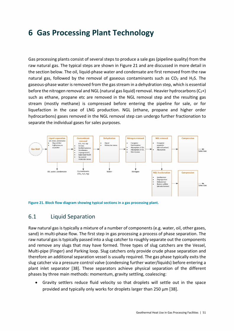
Geothermal Heat Use in Gas Processing Facilities | 51
6 Gas Processing Plant Technology
Gas processing plants consist of several steps to produce a sale gas (pipeline quality) from the raw natural gas. The typical steps are shown in Figure 21 and are discussed in more detail in the section below. The oil, liquid-phase water and condensate are first removed from the raw natural gas, followed by the removal of gaseous contaminants such as CO2 and H2S. The gaseous-phase water is removed from the gas stream in a dehydration step, which is essential before the nitrogen removal and NGL (natural gas liquid) removal. Heavier hydrocarbons (C2+) such as ethane, propane etc are removed in the NGL removal step and the resulting gas stream (mostly methane) is compressed before entering the pipeline for sale, or for liquefaction in the case of LNG production. NGL (ethane, propane and higher order hydrocarbons) gases removed in the NGL removal step can undergo further fractionation to separate the individual gases for sales purposes.
Figure 21. Block flow diagram showing typical sections in a gas processing plant.
6.1 Liquid Separation
Raw natural gas is typically a mixture of a number of components (e.g. water, oil, other gases, sand) in multi-phase flow. The first step in gas processing a process of phase separation. The raw natural gas is typically passed into a slug catcher to roughly separate out the components and remove any slugs that may have formed. Three types of slug catchers are the Vessel, Multi-pipe (Finger) and Parking loop. Slug catchers only provide crude phase separation and therefore an additional separation vessel is usually required. The gas phase typically exits the slug catcher via a pressure control valve (condensing further water/liquids) before entering a plant inlet separator [38]. These separators achieve physical separation of the different phases by three main methods: momentum, gravity settling, coalescing:
• Gravity settlers reduce fluid velocity so that droplets will settle out in the space provided and typically only works for droplets larger than 250 µm [38].
52 | Geothermal Heat Use in Gas Processing Facilities
• Centrifugal separators use centrifugal forces to separate out different phases. They can be particularly useful for gas streams with high particulate loading, and can be used to separate out droplet sizes greater than 100 µm.
• Coalescers are used for fine aerosol mist removal. They use diffusion and direct interception to separate out the mist/aerosol. Generally, high efficiency gas-liquid coalescers are used for inlet aerosol concentrations of a few thousand parts per million (ppm wt%) and are placed downstream of other bulk removal separators as the final purification stage [38].
6.2 Contaminant Removal
The general contaminants removed at this stage are CO2, H2S and Hg (mercury), but may include sulphur containing contaminants of lower concentrations such as COS, CS2 and mercaptans. The removal of CO2 and H2S is usually termed gas sweetening.
6.2.1 Gas Sweetening (CO2 and H2S Removal)
Australian natural gas sources have a wide range of CO2 concentrations, but usually contain low concentrations of H2S. A gas stream containing one or both of these components is referred to as a sour stream, and the removal process as gas sweetening.
Gas sweetening processes based on absorption include the use of amines, high temperature potassium bicarbonate (Benfield, Catacarb, Flexsorb HP processes), and ambient temperature sodium and potassium carbonate systems. The Catacarb process uses a catalysed hot potassium carbonate solution, while the Flexsorb process uses a sterically hindered amine as the activator. When choosing the gas conditioning process for the Longford plant, Esso Australia found the ExxonMobil Flexsorb PS and Flexsorb SE processes to be less attractive than a formulated amine process. Similarly the Varanus Island plant uses an amine (MDEA) process [39].
Ambient temperature systems include the Seaboard process, which is an older process and has been largely superseded by the Vacuum Carbonate Process. The Vacuum Carbonate process recovers H2S in a concentrated usable form. Its application is primarily for coke-oven gas. The Vacasulf process is also primarily applied to coke-oven gas. Ambient temperature potassium carbonate systems such as the Tripotassium phosphate and the Sodium Phenolate process have been superseded by other technologies [40].
Liquid phase oxidation processes include the Giammarco-Vetrocoke processes, developed in the 1950s and originally involving the use of toxic potassium and sodium arsenite solutions. Physical solvents are often considered when the raw gas stream is available at high pressure. Regeneration can be achieved by solvent flashing, leading to low energy requirements for the process. However, physical solvents will also absorb heavier hydrocarbons to some extent.
There are a number of physical solvent processes available for natural gas treating, however many are patented and thus can be expensive. Physical solvent methods include Selexol and

Geothermal Heat Use in Gas Processing Facilities | 53
Purisol (preferred for high H2S concentrations), Fluor solvent and mixed physical/chemical solvents such as Sulfinol, Amisol and Selefining [40].
Membranes can be used to separate gases by selective permeation of one or more gaseous components from one side of a membrane barrier to the other side. Gases such as H2S and CO2 will permeate through a membrane at a faster rate than hydrocarbons (methane, ethane etc) allowing separation, with the driving force for separation is the difference in the gaseous partial pressures [41].
Sweetening using membranes has been reported to have significant advantages over more conventional methods such as using aqueous amines. Membranes can be used by themselves or combined with aqueous amine sweetening. Membranes are particularly attractive for high feed gas pressure (over 35 bar) and/or high inlet CO2 composition (over 10%) [41]. Membranes are however not used commercially as the sole means of gas sweetening. This is because of permeation of desired gas components (methane slippage) across the membrane resulting in difficulties in meeting sweetening specifications. As such, membranes are better suited to bulk removal, however membrane robustness is also an issue not yet resolved [42]. Additionally, technology uptake by a traditionally conservative petrochemical industry has been slow with worries regarding membrane pretreatment. Processes involving membranes do not have a high heat requirement, with typical operating conditions of 40-50°C, and as such are not a good match for geothermal heat.
Further focus is given here to the Benfield (potassium bicarbonate), as used at Moomba and Ballera, and amine systems, as used at Wheatstone.
Benfield Process
In the Benfield process H2S and CO2 can be absorbed into aqueous alkaline solutions to form an acid in solution. The basic flow sheet is shown in Figure 22.
In the Benfield process, and with reference to Figure 22, the raw gas enters an absorption column (left) where it is contacted counter-currently with a lean solution of potassium carbonate. The sweet (purified) gas stream (with reduced CO2 and H2S) exits at the top of the column, while the rich solution exits from the bottom of the absorption column. This stream pressure is reduced and then passes into the regenerating/stripping column (right), which is used to remove the CO2 from the rich solution. The stripping column is operated with a reboiler, which is typically heated using steam. The lean solution exiting the bottom of the stripping column is pumped back to the absorption column where a fraction of the stream may be cooled and fed higher up the column. The separation of CO2 is driven by the difference in CO2 solubility in the absorber (high partial pressure) and the stripper (low partial pressure) and greater efficiencies can be expected with increased CO2 partial pressure in the feed gas [40].

54 | Geothermal Heat Use in Gas Processing Facilities
Figure 22. Flow diagram of a gas sweetening plant using the Benfield process [26].
Improvements to the Benfield process include the two stage Benfield LoHeat process, with internal steam generation, the Benfield LoHeat process with steam ejectors and mechanical vapour compression, and the Benfield HiPure process. The latter system incorporates an amine activator (DEA) and used in cases where extremely low CO2 product specifications are imposed [40].
The Benfield process is used in a number of gas treating facilities due to the low cost of the potassium carbonate solution. However, safety concerns relating to the use of vanadium-based corrosion inhibitors, and the requirement for heat tracing/steam can limit its use. This was the case for Esso Australia, who rejected the Benfield Process technology in favour of a formulated amine process for the Longford Gas Processing Plant. The technology also requires steam, which is not currently used at the Longford Plants [39].
The main energy requirement is process heat (usually low pressure steam) for the reboiler, and electricity for the recycle pump.
Amine Process
Aqueous amine based absorption/de-sorption processes are commonly used to remove CO2 and H2S from the natural gas stream, and a typical process is shown in Figure 23. In many cases, process requirements can be met by a number of different amines, and an economic analysis is required to make the final determination [40].

Geothermal Heat Use in Gas Processing Facilities | 55
Sour gas
Contaminants
Inlet separator
Sour gas
Absorber
Rich solvent
Gas
Rich solvent
Liquid hydrocarbons
Outlet separator Sweet gas
Solvent
Sweet gas
Mechanical filter
Lean/rich cross HX
H2SCO2
H2O
Condenser
Accumulator
Reflux
H2SCO2
Stripper
Reboiler
Surge tankCoolerMechanical filter
Carbon filter
Lean solvent
Figure 23. Standard amine based absorption process for removal of acid gases [38].
Natural gas enters the absorption column at the base and rises to contact counter-currently with the lean amine solvent. Packing and trays are typically used in the column to provide surface area for gas/liquid contact, though packing is now generally favoured [42]. The solvent absorbs the CO2 and H2S, causing a temperature increase in the absorption column. Sweet natural gas exits from the top of the absorption column. Depending on the vapour pressure of the solvent used, it may also pass through a wash section. Most amine solvents are aqueous, as such the gas stream leaving the amine plant will be saturated.
The rich solvent loaded with CO2 is typically flashed to the lower pressure of the regeneration column, releasing some CO2 and co-absorbed hydrocarbons. It then passes through the cross heat exchanger, before entering the stripping column. In the stripping column energy is provided at the base through the reboiler to strip the CO2 from the solvent. CO2 and steam (and H2S if present) leave from the top of the column and enter the condenser section. Here the majority of the steam is condensed and returned to the stripping column, leaving a high purity CO2 product stream. The regenerated lean solvent leaves from the base of the stripping column, passes through the cross heat exchanger, is pumped back up to the higher pressure of the absorption column, passes through a trim cooler and filter before being returned to the absorption column.
The main energy requirement is process heat (usually low pressure steam) for the reboiler, and electricity for the recycle pump (on the rich solvent stream, and not shown in Figure 23).
6.2.2 Hg Removal
If mercury is present in the raw natural gas stream it could result in severe corrosion of aluminium, such as brazed aluminium heat exchangers in LNG (liquefied natural gas) and turboexpander plants [40]. Mercury also needs to be removed to comply with the Australian Standard (AS4564) for Pipeline-quality natural gas specifies the level of mercury at 1µg/m3.

56 | Geothermal Heat Use in Gas Processing Facilities
Options for removing mercury include non-regenerative methods such as sulphided metal oxides on alumina, metal oxides on carbon, and sulphur impregnated activated carbon. In the latter case sulphur is used to fix mercury as a sulphide in the carbon structure [40]. The Longford Gas Processing plant has chosen sulphided metal oxide on alumina for mercury removal from natural gas originating from offshore gas fields in the Bass Strait [33].
Silver-coated molecular sieves can be used as a regenerative means of removing the mercury, but require a regeneration cycle. The released mercury can be captured using a separate smaller non-regenerative bed.
6.2.3 Dehydration
Raw natural gas is saturated with water at the conditions (temperature and pressure) exiting the wellhead. Process steps such as gas sweetening (removal of CO2 and H2S) may also saturate the gas stream with water. As a result, gas dehydration (water removal) may be required for the following reasons [41]:
• to prevent hydrate formation and water condensation in downstream processes, • to meet water specifications in the natural gas product stream, and • to prevent corrosion.
Natural gas dehydration can be achieved by a number of processes, including absorption using liquid (such as glycol) or solid desiccants (such as alumina, silica gel, molecular sieves), refrigeration, membrane permeation, gas stripping, distillation and calcium chloride [41]. The most commonly used processes are glycol and solid desiccants.
Glycol absorption
Glycol dehydration is favoured where dew point depressions between 15°C and 49°C are required. Diethylene glycol (DEG), triethylene glycol (TEG) and tetraethylene glycol (TREG) are used, however TEG is most commonly used for natural gas dehydration [41]. The layout of a typical glycol dehydration plant is shown in Figure 24.

Geothermal Heat Use in Gas Processing Facilities | 57
Wet gas inlet
Water vapour
Free liquid
Glycol contactor
Lean glycol
Dry gas
Flash tank
Filter
Surge drum
Reboiler
Flash gas
Figure 24. Flow diagram of a typical glycol dehydration process [41].
In typical operation (and with reference to Figure 24), the natural gas stream enters a glycol contactor (left), where the water content is absorbed by the glycol, while the dry gas exits at the top of the contactor and may pass through a heat exchanger. The rich glycol stream exits near the bottom of the contactor and is heated before entering a glycol flash tank (centre). The stream is further heated and then filtered before entering the glycol reconcentrator/stripper (still) (top right) to distil off (strip) the water content at elevated temperatures. The lean glycol stream exits the reboiler, passing through a surge tank before being cooled and pumped back to the top of the glycol contactor. Heat is supplied to the glycol stripper via a reboiler. The maximum reboiler temperature depends on the type of glycol being used. For TEG at near-atmospheric pressures the maximum temperature is 205°C, after which the glycol starts to degrade. Regeneration in the stripper can be enhanced by lowering the water vapour partial pressure in the gas phase, and can be achieved via gas injection, azeotrope formation and vacuum stripping [40]. Vacuum stripping is however not generally utilised due to the added complexity and because the same result can generally be achieved more cheaply using stripping gas [43].
The main energy requirement for a glycol process is process heat (high pressure steam or fuel burner) for the reboiler, and electricity for the recycle pump.
Solid dessicants
Solid desiccant units are generally more expensive to buy and operate than glycol units. Liquid desicants cannot reach very low dewpoints and therefore solid desiccants are only used in gas processing plants when very low water dewpoints are required. Common desiccants include gels of alumina or silica, alumina, and molecular sieves. Molecular sieves produce the lowest water dewpoints, their equilibrium water capacity is less dependent on the adsorbing tower temperature, but they are usually more expensive [41].
Systems based on solid dessicants are based on two or more towers, with a typical layout for molecular sieves shown in Figure 25. One tower is used to capture water from the gas stream,

58 | Geothermal Heat Use in Gas Processing Facilities
via adsorption onto the molecular sieves, while the other tower undergoes regeneration. Hot gas is typically used to regenerate the molecular sieves by driving off the adsorbed water at elevated temperatures. This is followed by cooling with an unheated gas stream before the tower is prepared for the adsorption phase. A fraction of the dry exit gas can be used in the regeneration, as shown in Figure 25, but other gas streams can also be used, such a fraction of the natural gas stream after compression (as implemented by Moomba). The regeneration temperature is typically around 215°C, with process gas heated to 260-370°C to heat the regenerated tower, packing and water, and cover the heat of water desorption [40]. The regeneration gas stream is typically heated using a gas heater.
The main energy requirement for dehydration using molecular sieves is process heat (fuel burner) to heat the regeneration gas.
Figure 25. Flow diagram of typical natural gas dehydration process using molecular sieves [41].
6.2.4 Nitrogen Removal
Nitrogen levels in raw natural gas are usually low and removal is uncommon in Australian gas processing plants. When required, cryogenic removal of nitrogen is a common method requiring typical operating temperatures of -160°C to -190°C in the coldest sections. Because of this operation, any impurities in the gas stream which might form solid phases need to be removed before the nitrogen removal stage. Impurities which require removal include water, CO2, H2S, methanol and ethylene glycol [40].
Two processes suitable for cryogenic removal of nitrogen from natural gas are shown in Figure 26. The single-column heat-pumped cycle (left) is capable of producing high pressure nitrogen, but has an added heat pump compressor. The double-column heat-pumped cycle (right) is favoured for high pressure gas containing a relatively high concentration of nitrogen [40].

Geothermal Heat Use in Gas Processing Facilities | 59
The main energy requirement is electricity for the compressors and refrigeration cooling.
(a) (b)
Figure 26. Flow diagram of (a) single-column heat-pumped cycle, and (b) double-column heat-pumped cycle for the removal of nitrogen [40].
6.2.5 NGL Removal
The NGL content (C2+ hydrocarbons), such as ethane, propane, butane etc is removed from the gas stream to produce a very high methane content sale gas. Two primary ways of conducting this are via absorption and via a cryogenic expander (fractionation).
The NGL absorption is conducted using absorbing oil, in a similar way to glycol dehydration. Lean oil is used to capture the NGLs in an absorption column. The rich oil stream is passed to a lean oil stripper/still at elevated temperature (or steam stripping) to recover the NGLs for further processing [41].
Fractionation can also be used to separate NGLs from the methane-rich gas stream. Fractionation is based on separating various components based on their relative volatility and dependant also on the required purity of the product stream. The layout of a typical fractionation column is shown in Figure 27. Feed gas enters a column consisting of trays or packing to promote contact of liquid and vapour streams.
A fractionator used for NGL removal is commonly referred to as a demethaniser. In this case the gas stream is first cooled to sub-zero (cryogenic) temperatures, using refrigerants, before entering the demethaniser column. A fraction of the gas stream may also be expanded rapidly (pressure reduced) in an expander/expander turbine to reduce the inlet gas temperature even further. The NGLs are removed as a liquid from the bottom of the column, while the methane-rich gas stream is removed from the top of the column. Typical operating pressures are between 13 and 27 bar,a [41].

60 | Geothermal Heat Use in Gas Processing Facilities
The main energy requirement is process heat for the reboiler, refrigerants for the gas cooling, and electricity for various pumps.
Figure 27. Diagram showing general layout of a fractionation column [41].
6.2.6 NGL Fractionation
Cryogenic systems are required for high recovery of the higher order hydrocarbons. The extraction of ethane and heavier gases are therefore based on the economic viability of their extraction and sale thereof. Additional fractionation columns are added to achieve this separation, with an example of three stages given in Figure 28. Typical additional stages are termed as follows:
• Deethaniser – separation of ethane (C2) • Depropaniser – separation of propane (C3) • Debutaniser – separation of butane (C4) • Deisobutaniser/Butane splitter – separation of isobutane (iC4) and butane (C4)
The main energy requirement is process heat for the reboiler (usually low pressure steam), refrigerants for gas cooling, and electricity for various pumps. The gas flows become sequentially lower with additional fractionation stages, and is related to the concentration of the removed gaseous constituents. The related energy requirements for each subsequent stage therefore also become lower.
The Moomba gas processing plant has a deethaniser installed for the recovery and compression of ethane for sales purposes.

Geothermal Heat Use in Gas Processing Facilities | 61
Figure 28. Flow diagram showing example of a fractionation train for the separation of ethane, propane and butane column [41].
6.2.7 Compression
The methane-rich gas exiting the demethaniser (typically operating between 13 bar,a and 27 bar,a) needs to be compressed before entering the pipeline. The initial compression can be done through compressors integrated with the demethaniser expanders (see Section 6.2.5), thereby converting some of the energy released during gas expansion (and hence gas cooling) upstream of the demethaniser to recompressing the methane-rich gas stream, as utilised at the Moomba gas processing plant [44]. The remaining compression is conducted in a separate compressor. The main energy requirement in this stage is electricity for the remaining compression.
Any additional sales gas streams, such as ethane or propane, need to be compressed to the required value for intermediate storage, or for transport to point of sale/usage. The main energy requirement in this stage is electricity for the gas compression.

62 | Geothermal Heat Use in Gas Processing Facilities
7 Major Sources of Energy Utilisation in an Australian Gas Processing Plant
Energy is required in a gas processing plant for applications such as heating, cooling, refrigeration, pumping, compression etc. The energy can be in the form of electricity, steam, thermal fluid, or direct gas-fired furnaces. Gas processing plants are generally designed with good energy integration. Examples are the use of hot process streams to preheat cooler process streams via heat exchangers, or expanders coupled to compressors where a high pressure gas is expanded to produce the work required to drive a compressor.
Heat can also be derived via waste heat recovery units (WHRU) which can be installed on gas compressor turbines. The heat from the exhaust gas of the compressor gas turbines can be utilised elsewhere in the plant, such as in the planned Longford gas conditioning plant where the WHRU supplements a hot oil heater to supply heat to the amine regenerator reboilers [39].
However, residual energy is still required in parts of a gas processing plant, for instance for pumps or where energy integration is not possible, based on the physical location, temperature, heat load etc. For these cases ‘over the fence’ energy can be obtained from on- or near-grid processing plants in the form of gas, electricity or geothermal energy. If this is not available, then a fraction of the sales natural gas is used to fire furnaces, or generate high pressure steam, which is in turn used as a heat source in the plant, or to raise electricity for equipment such as pumps and compressors.
7.1 Major Energy Requirements for an Gas Processing Plant for Pipeline Grade Gas
The process steps in a general gas processing plant (for pipeline grade production) are given in Figure 29. In an Australian context, the raw natural gas mercury and nitrogen levels are typically very low and therefore these removal steps have been disregarded in determining major energy requirements. Similarly, C2+ (ethane, propane, butane etc) levels are typically low in comparison to the CH4 (methane) and CO2 levels resulting in NGL fractionation (e.g. deethaniser, depropaniser etc) only required in certain cases where these gas levels are sufficiently high and the economic viability of their extraction is warranted by their sale price. Gas plant LPG (butane and propane) and ethane in Australia comes mainly from the North West Shelf LNG gas processing plant at Karratha, the Gippsland gas processing plant and several smaller new gas processing plants near Victoria in the South East and the Moomba gas processing plant in the Cooper basin [45].

Geothermal Heat Use in Gas Processing Facilities | 63
Figure 29. Major energy requirements in an Australian gas processing plant, with a reference raw natural gas flow of 125 MMscfd.
The energy values and operating temperatures presented in Figure 29 are based on a raw natural gas flow of 125 MMscfd (million standard cubic feet of natural gas per day) and are estimated for a range of inlet gas conditions including pressure, temperature and CO2 concentration.
The following information relates to the major energy requirements (heat and electricity) in a typical Australian gas processing plant. Information relating to refrigeration or cooling requirements in the gas processing plant is not covered here, as this type of energy requirement cannot be derived easily from geothermal heat.
7.1.1 Gas Sweetening
The major energy requirement in a typical Australian gas processing plant is in the gas sweetening step. The reboiler at the bottom of the stripping column requires between 10 MWth and 55 MWth for aqueous amine (MDEA) stripping (see more detailed results in Section 8.2), while values of 10 MWth to 30 MWth are estimated for the Benfield process depending on the technology utilised [40]. A value of 26 MWth has been estimated and scaled from 2002 Moomba plant operation values [26]. The typical reboiler operating temperatures are 110-125°C for both technologies. However lower reboiler temperatures can be achieved by stripping at or just below atmospheric pressure (see Section 8.2 for more details of reduced pressure stripping calculations).
Electricity is required for the recycle pump, and values of 0.9-3.6 MWe are calculated for aqueous amine (MDEA) stripping, while values of 1 MWe or lower are estimated for the Benfield process based on scaled operation at the Moomba gas processing plant [44].

64 | Geothermal Heat Use in Gas Processing Facilities
7.1.2 Gas Dehydration
The second largest heat requirement in a typical Australian gas processing plant is in the gas dehydration step. For removal based on molecular sieves, hot gas is required to regenerate the molecular sieves. The regeneration itself occurs typically between 215°C and 220°C. However the gas used for regeneration has to be heated to much higher temperatures (260-370°C) to account for heat of the regenerated tower, packing and water, and cover the heat of water desorption [40]. The heat requirement is estimated between 0.7 MWth and 2 MWth for the gas heating required.
For removal based on glycol absorption, heat is required in the reboiler on the stripper column. The column typically operates at 200°C using TEG, while lower temperatures are required for DEG absorption (160°C). The reboiler heat requirement is estimated between 0.2 MWth and 2.5 MWth, based on a range of gas inlet conditions and operating conditions (see more detailed results in Section 8.3).
7.1.3 NGL Removal and Fractionation
The NGL removal and fractionation (separate removal) of ethane and higher order hydrocarbon gases is site-specific, and highly dependent on inlet gas composition and economic viability of their (C2+) extraction.
Excluding refrigeration, the major energy requirement in a NGL fractionation train is heat for the distillation column reboiler. The reboiler temperature is dependent on the vapour pressure of the gas components, resulting in deethaniser reboiler temperatures potentially between 70°C and 120°C. Reboiler temperatures between 90°C and 100°C are estimated for the deethaniser reboiler at the Moomba gas processing plant. The Moomba deethaniser reboiler duty is estimated at 3-4 MWth (for 125 MMscfd operation).
The latter fractionation steps (depropaniser, debutaniser etc.), where present, have progressively reduced gas inlet volumes and hence progressively lower reboiler duties. The heat requirements are therefore low and not regarded further in this study.
7.1.4 Compression
The exit pressure of the natural gas product stream is dependent on the pipeline specifications. The natural gas may therefore require compression after the demethaniser step (where present), to raise the pressure from the demethaniser operating pressure, which is typically between 13 and 27 bar,a [41]. Compression is also required for the ethane and other fractionated product streams, if present.
The compression energy has also been estimated as 3.5 MWe for the natural gas stream and 0.6 MWe for the ethane product stream, based on scaled operation at the Moomba gas processing plant [44].

Geothermal Heat Use in Gas Processing Facilities | 65
7.1.5 Pumps
Pumps are used in a gas processing plant to transport a liquid stream from one vessel to another, and increase the liquid pressure, if required, to the operating pressure of the latter vessel. Typical pump locations are in the sweetening and dehydration steps where they are used to recycle the absorbent liquid from the stripping column to the absorbing column. They can also be used in the demethaniser step to pump liquid fractions requiring external heating (via heat exchange) back to the demethaniser column. Pumps are used in subsequent fractionation steps to transport the liquid product from the bottom of the preceding fractionation column to the next fractionation step.
The recycle pumps for the sweetening step are estimated to have the highest electrical energy requirement, with estimates of 0.9-3.6 MWe for aqueous amine (MDEA) absorption (see Section 8.2). The remaining pumps are estimated to have a much lower electrical energy requirement, typically below 1 MWe each.
7.2 Qualitative Assessment of Primary Energy Requirements in Gas Processing Facilities
A qualitative comparison was made of energy requirements for a generalised gas processing plant, in an Australian context, based on the concentration of CO2 and NGLs in the feed, and for low and high inlet gas pressures. These were compared with a gas processing plant producing LNG. The energy requirements were separated into low pressure steam (MWth), high pressure steam (MWth), compression (MWe) and refrigeration (MWth), with the estimated energy requirements given in Figure 30. The inlet gas conditions and assumptions relating to gas sweetening, gas dehydration, NGL removal, compression and natural gas liquefaction (for LNG scenario) steps are given in Appendix A. The results in Figure 30 only consider the refrigeration required for cooling of the demethaniser gas inlet stream (Scenarios 5-8), as well as liquefaction of the natural gas for the LNG scenarios (7+8). The scenarios considered are as follows:
1. Low CO2 (2 vol%) concentration in the raw natural gas, at a low pressure (10 bar,a) 2. Low CO2 (2 vol%) concentration in the raw natural gas, at a high pressure (75 bar,a) 3. High CO2 (20 vol%) concentration in the raw natural gas, at a low pressure (10 bar,a) 4. High CO2 (20 vol%) concentration in the raw natural gas, at a high pressure (75 bar,a) 5. High CO2 and NGL (20% and 10% respectively) concentration in the raw natural gas,
at a low pressure (10 bar,a) 6. High CO2 and NGL (20% and 10% respectively) concentration in the raw natural gas,
at a high pressure (75 bar,a) 7. High CO2 and NGL (20% and 10% respectively) concentration in the raw natural gas, at
a low pressure (10 bar,a), used for LNG 8. High CO2 and NGL (20% and 10% respectively) concentration in the raw natural gas,
at a high pressure (75 bar,a), used for LNG

66 | Geothermal Heat Use in Gas Processing Facilities
Figure 30. Estimated normalised heat and electrical requirements for gas processing plants with low and high CO2 feed concentrations, feed with NGLs present, and LNG plants. Energy values given per kmol of CH4 produced.
The estimated energy requirements in Figure 30 are normalised and reported per kmol of methane produced. The results show higher normalised energy requirements for the low pressure raw natural gas streams. In Scenarios 1 and 2, with a low CO2 concentration in the raw natural gas, there is no sweetening step and the major energy requirement (electrical) is for the compression of the product gas stream.
In Scenarios 3 and 4, the results with a high CO2 inlet concentration shows that the normalised energy requirements (excluding low pressure steam) are all lower than for the low CO2 inlet concentration scenarios (1 and 2).
For Scenarios 3 to 8, the results show that the major energy requirement is low pressure steam, required by the reboiler in the gas sweetening step. High pressure steam requirement (used for gas dehydration) is significantly lower, while electrical energy for compression is appreciable.
For the LNG scenarios (7 and 8) the CO2 exiting the gas sweetening step has to be much lower (50 ppm vol% [6]) than in the other scenarios (2 vol%) to avoid CO2 condensation during downstream natural gas liquefaction. Therefore the LNG scenarios have a higher demand for low pressure steam compared to the other scenarios.
Refrigeration is needed in the demethaniser (NGL removal) step for Scenarios 5-8, where the inlet gas contains NGLs. Additionally, for the LNG scenarios (7 and 8), the demethaniser gas exit stream is cooled to -155°C to liquefy the natural gas. This results in a high energy requirement for refrigeration in the LNG scenarios.

Geothermal Heat Use in Gas Processing Facilities | 67
Final stage compression is not required for the LNG scenarios (7 and 8). Intermediary compression is however required for Scenario 7 (low inlet pressure scenario) prior to the demethaniser step to raise the pressure of the gas to 27 bar,a.
The results in Figure 30 show that the major energy requirement is in the form of low pressure steam, which is used in the sweetening step. Lower energy amounts are required for compression, and for refrigeration (in the case of LNG plants). The lowest energy requirement is generally in the form of high pressure steam, which is used in the dehydration step.
The energy required for compression and refrigeration cannot be derived easily from geothermal heat. The remaining two large energy requirements are therefore in the form of low and high pressure steam. Of these, the major energy requirement is for the gas sweetening step (low pressure steam) while a much lower amount is required for the gas dehydration step (high pressure steam). These two process steps are further investigated in the subsequent report sections.

68 | Geothermal Heat Use in Gas Processing Facilities
8 Mass & Energy Balances and Design of Identified Major Energy Processing Steps
The major energy requirements in a typical Australian gas processing plant were identified in Section 7. The major heat requirements are in the sweetening and dehydration steps, while the major electricity requirement is in the sweetening and compression step.
The fractionation (separate removal) of ethane and higher order hydrocarbon gases is site-specific, and highly dependent on economic viability of their extraction. Additionally, the fractionation steps (deethaniser, depropaniser, debutaniser etc.), where present, have progressively reduced gas inlet volumes and hence progressively lower reboiler duties. In terms of geothermal energy integration, the NGL fractionation steps are not considered further in this study.
Refrigeration and cooling requirements are not investigated further, in terms of possible integration with geothermal energy.
The gas sweetening and dehydration steps are therefore the two gas processing steps, in an Australian context, which are considered further for potential integration of geothermal energy, and hence the mass & energy balances for these processing steps have been investigated, coupled with more detailed design of the absorbing and stripping columns and associated pumps, reboilers, condensers and heat exchangers. The information relating to the reboilers and recycle pumps are shown in Section 8, while the assumptions used for the sizing of the column, condensers, heat exchangers are given in Appendix E and Appendix F. This information is used further in the development of a capital cost in Sections 11 and 14.
Three inlet raw gas stream CO2 concentrations were considered (10%, 21% and 40%), representing a low, medium and high concentration. These streams were taken as input into ProTreat® modelling of an aqueous amine absorption step, and subsequent outlet gas used as input into the design of a glycol dehydration step.
8.1 Inlet Gas Conditions
A raw natural gas flow rate of 125 MMscfd, at 49°C and 75.1 bar,a was used as the inlet gas flow conditions to the processing plant. Inlet saturated and dry gas streams with CO2 concentrations of 10%, 21% and 40% were investigated, and the concentration of the other gas components were scaled accordingly. The saturated raw gas inlet concentrations considered for simulation calculations are given in Table 5, representing a low, medium and high CO2 concentration scenario.
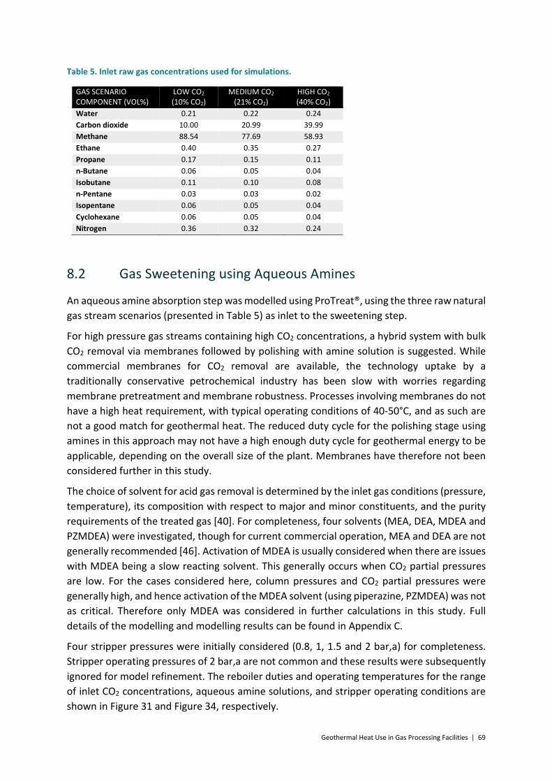
Geothermal Heat Use in Gas Processing Facilities | 69
Table 5. Inlet raw gas concentrations used for simulations.
GAS SCENARIO COMPONENT (VOL%)
LOW CO2 (10% CO2)
MEDIUM CO2 (21% CO2)
HIGH CO2 (40% CO2)
Water 0.21 0.22 0.24 Carbon dioxide 10.00 20.99 39.99 Methane 88.54 77.69 58.93 Ethane 0.40 0.35 0.27 Propane 0.17 0.15 0.11 n-Butane 0.06 0.05 0.04 Isobutane 0.11 0.10 0.08 n-Pentane 0.03 0.03 0.02 Isopentane 0.06 0.05 0.04 Cyclohexane 0.06 0.05 0.04 Nitrogen 0.36 0.32 0.24
8.2 Gas Sweetening using Aqueous Amines
An aqueous amine absorption step was modelled using ProTreat®, using the three raw natural gas stream scenarios (presented in Table 5) as inlet to the sweetening step.
For high pressure gas streams containing high CO2 concentrations, a hybrid system with bulk CO2 removal via membranes followed by polishing with amine solution is suggested. While commercial membranes for CO2 removal are available, the technology uptake by a traditionally conservative petrochemical industry has been slow with worries regarding membrane pretreatment and membrane robustness. Processes involving membranes do not have a high heat requirement, with typical operating conditions of 40-50°C, and as such are not a good match for geothermal heat. The reduced duty cycle for the polishing stage using amines in this approach may not have a high enough duty cycle for geothermal energy to be applicable, depending on the overall size of the plant. Membranes have therefore not been considered further in this study.
The choice of solvent for acid gas removal is determined by the inlet gas conditions (pressure, temperature), its composition with respect to major and minor constituents, and the purity requirements of the treated gas [40]. For completeness, four solvents (MEA, DEA, MDEA and PZMDEA) were investigated, though for current commercial operation, MEA and DEA are not generally recommended [46]. Activation of MDEA is usually considered when there are issues with MDEA being a slow reacting solvent. This generally occurs when CO2 partial pressures are low. For the cases considered here, column pressures and CO2 partial pressures were generally high, and hence activation of the MDEA solvent (using piperazine, PZMDEA) was not as critical. Therefore only MDEA was considered in further calculations in this study. Full details of the modelling and modelling results can be found in Appendix C.
Four stripper pressures were initially considered (0.8, 1, 1.5 and 2 bar,a) for completeness. Stripper operating pressures of 2 bar,a are not common and these results were subsequently ignored for model refinement. The reboiler duties and operating temperatures for the range of inlet CO2 concentrations, aqueous amine solutions, and stripper operating conditions are shown in Figure 31 and Figure 34, respectively.

70 | Geothermal Heat Use in Gas Processing Facilities
Figure 31 shows the variation in the reboiler duty for all amines, while Figure 32 shows more detail of the reboiler duty for MDEA and PZMDEA only. The reboiler duty is largely influenced by the choice of aqueous amine, with the MEA results being significantly higher than the rest. The results show a general decrease in the reboiler duty with an increase in the stripper operating pressure for MEA and PZMEA. Figure 33 shows only the results for MDEA and shows the estimated Moomba (based on Benfield process) reboiler duty as reference (estimated to have an inlet CO2 concentration of 21%). The reboiler duty values increase as a function of the stripper operating pressure, when using aqueous MDEA. Higher solvent flow rates are required to remove CO2 at increased concentrations. The reboiler duties are therefore higher for gas streams containing higher CO2 concentrations. The Benfield process reboilers at Moomba were estimated to have a reboiler duty of 27 MWth (scaled for operation at 125 MMscfd), which corresponds well with MDEA results using 21% CO2 inlet concentrations.
The reboiler temperature is a function of the choice of amine and operating pressure, as shown in Figure 34, where higher stripper operating pressures result in higher reboiler temperatures. The reboiler temperature is a function of the flow of aqueous amine solvent. The aqueous amines have similar structures and therefore similar boiling points can be expected, for a given stripper operating pressure [42]. This is shown in Figure 34 where the reboiler temperatures are only mildly influenced by the choice of aqueous amine. Reboiler temperatures of ~115°C are required for a stripper pressure of 1.5 bar,a, while lower reboiler temperatures can be achieved with decreased stripper pressures. A reboiler temperature of ~103°C is required for operation near atmospheric pressure, while a temperature of ~96°C is required for slight vacuum stripper operation.
Operation at slightly vacuum conditions favours the utilisation of geothermal heat at lower temperatures due to reduced reboiler temperatures and hence lower geothermal brine outlet temperatures. However, operation under vacuum in the stripper is usually not considered unless it is absolutely necessary due to:
• Safety implications of air ingress into a natural gas environment, • Requirement for a vacuum pump (additional process step), and • Larger CO2 compression requirement if considering CO2 sequestration.
The MDEA results were used further as a stream input to the dehydration step as detailed in Section 8.3. The MDEA results were also used further in Section 9.1 to determine the amount of geothermal brine required to supply the required boiler duty, instead of using low pressure steam.

Geothermal Heat Use in Gas Processing Facilities | 71
Figure 31. Calculated reboiler duties for aqueous amine capture of CO2, showing effect of inlet CO2 concentration and stripper column pressure.
Figure 32. Calculated reboiler duties for MDEA and PZMDEA capture of CO2, showing effect of inlet CO2 concentration and stripper column pressure.
0
50
100
150
200
250
300
0 0.5 1 1.5 2 2.5
Rebo
iler d
uty
(MW
th)
Stripper pressure (bar,a)
MEA, 40% CO2
MEA, 21% CO2
MEA, 10% CO2
MDEA, 40% CO2
MDEA, 21% CO2
MDEA, 10% CO2
PZMDEA, 40% CO2
PZMDEA, 21% CO2
PZMDEA, 10% CO2
DEA, 40% CO2
DEA, 21% CO2
DEA, 10% CO2
0
20
40
60
80
100
0 0.5 1 1.5 2 2.5
Rebo
iler d
uty
(MW
)
Stripper pressure (bar,a)
MDEA, 40% CO2
MDEA, 21% CO2
MDEA, 10% CO2
PZMDEA, 40% CO2
PZMDEA, 21% CO2
PZMDEA, 10% CO2

72 | Geothermal Heat Use in Gas Processing Facilities
Figure 33. Refined reboiler duties for aqueous MDEA capture of CO2, showing effect of inlet CO2 concentration and stripper column pressure.
Figure 34. Calculated reboiler temperatures for aqueous amine capture of CO2, showing effect of inlet CO2 concentration and stripper column pressure.
0
10
20
30
40
50
60
0 0.5 1 1.5 2
Rebo
iler d
uty
(MW
th)
Stripper pressure (bar,a)
MDEA, 40% CO2
MDEA, 21% CO2
MDEA, 10% CO2
Moomba Benfield
90
95
100
105
110
115
120
125
0 0.5 1 1.5 2 2.5
Rebo
iler t
empe
ratu
re (°
C)
Stripper pressure (bar,a)
MEA, 40% CO2
MEA, 21% CO2
MEA, 10% CO2
MDEA, 40% CO2
MDEA, 21% CO2
MDEA, 10% CO2
PZMDEA, 40% CO2
PZMDEA, 21% CO2
PZMDEA, 10% CO2
DEA, 40% CO2
DEA, 21% CO2
DEA, 10% CO2

Geothermal Heat Use in Gas Processing Facilities | 73
Figure 35. Calculated recycle pump duties for aqueous amine capture of CO2, showing effect of inlet CO2 concentration and stripper column pressure.
8.3 Gas Dehydration using Glycol Absorption
A glycol-based dehydration step was modelled using ProTreat® and using the worked examples provided in the GPSA Engineering Data Book [41]. Gas flows, concentrations, temperatures and pressures exiting the MDEA sweetening step (as detailed in Section 8.2) were used as the inlet to the glycol contactor (absorber). TEG was chosen as the liquid desiccant as it is the most commonly used glycol for natural gas dehydration. It was assumed that the gas stream will be dehydrated to 100 mg/Sm3 water content. The stripper column pressure was held constant at approximately atmospheric pressure (105 kPa) and a reboiler temperature of 200°C was used, as thermal decomposition of TEG is an issue at higher temperatures. Full details of the modelling and modelling results can be found in 0, together with a sensitivity analysis on the stripper pressure and choice of glycol.
The reboiler and recycle pump duties for the range of original CO2 inlet concentrations (to the MDEA sweetening section) are shown in Figure 36. The reboiler duties are much smaller than those for the sweetening step (cf ~300 kWth and ~25 MWth). The TEG reboiler duty is related to the water content of the gas entering the dehydration step - higher inlet water content results in a higher solvent circulation rate and therefore a higher reboiler duty. The entering water content is a function of the conditions leaving the upstream sweetening step with higher water content associated with a lower gas stream pressure, higher temperature and higher acid gas content (CO2 and H2S). The dehydration inlet conditions were modelled for this study as ~75.1 bar,a and ~50°C with <2 vol% CO2.
0
1
2
3
4
5
6
0 0.5 1 1.5 2 2.5
Recy
cle
pum
p du
ty (M
Wth
)
Stripper pressure (bar,a)
MEA, 40% CO2
MEA, 21% CO2
MEA, 10% CO2
MDEA, 40% CO2
MDEA, 21% CO2
MDEA, 10% CO2
PZMDEA, 40% CO2
PZMDEA, 21% CO2
PZMDEA, 10% CO2
DEA, 40% CO2
DEA, 21% CO2
DEA, 10% CO2

74 | Geothermal Heat Use in Gas Processing Facilities
The results in Figure 36 show a decrease in the TEG reboiler duty with increases in the original CO2 inlet concentration to the upstream sweetening step. There is also a related decrease in the recycle pump duty. The main reason is that, for a constant raw natural gas feed rate (125 MMscfd), higher CO2 inlet concentrations result in lower gas volumes exiting the gas sweetening step. This results in lower gas volumes (as shown in Figure 36), for a constant raw natural gas feed rate, requiring dehydration (and subsequent steps) and the heating and electrical requirements are therefore lower for higher CO2 inlet concentrations.
Figure 36. Calculated reboiler and recycle pump duties for TEG dehydration of natural gas stream, showing effect of original CO2 inlet concentration to the sweetening step. Reboiler temperature = 200°C.
8.4 Further Gas Processing Required
The composition of the gas stream exiting the dehydration step (Section 8.3) is given in Table 6.
Table 6. Calculated gas composition and properties exiting the dehydration step.
Component 10% CO2 Case Vol%
21% CO2 Case Vol%
40% CO2 Case Vol%
Water 0.01 0.01 0.01 CO2 2.00 2.00 2.00 Methane 96.64 96.63 96.62 Ethane 0.43 0.43 0.44 Propane 0.18 0.19 0.18 n-Butane 0.07 0.06 0.07 Isobutane 0.12 0.12 0.13 n-Pentane 0.03 0.04 0.03
0
15
30
45
60
75
90
105
120
135
150
0
50
100
150
200
250
300
350
400
450
500
0% 10% 20% 30% 40% 50%In
let g
as fl
ow to
dey
drat
ion
(MM
scfd
)
Duty
(kW
)
Original CO2 inlet concentration (%)
Recycle pump
Reboiler
Inlet gas flow

Geothermal Heat Use in Gas Processing Facilities | 75
Isopentane 0.07 0.06 0.07 Cyclohexane 0.06 0.06 0.06 Nitrogen 0.39 0.40 0.39 Gas flow rate (MMscfd)
110.6 96.9 73.1
Gas temperature (°C)
55.1 54.7 54.3
Gas pressure (bar,a)
74.9 74.9 74.9
Gas density (kg/m3) 0.715 0.715 0.715 Air density (standard conditions) (kg/m3)
1.202 1.202 1.202
Relative density (-) 0.595 0.595 0.595 Wobbe Index (MJ/Sm3)
48.40 48.40 48.41
Gross heating value (MJ/Sm3)
37.33 37.32 37.34
The calculated Wobbe Indices (as shown in Table 6) are within the range (46 – 52 MJ/Sm3) required by the Australian Standard for pipeline quality gas (AS 4564-2011) and the gross heating values are also below the maximum (42.3 MJ/Sm3) specified by the standard [5]. The exit gas streams also comply with the requirements for oxygen content, hydrogen sulphide, total sulphur, water content, hydrocarbon dewpoint, total inert gases and oil content.
The exit gas streams therefore do not need further gas processing steps and therefore steps such as NGL removal and NGL fractionation were not considered here.
Additionally, the exit gas stream is at 74.9 bar,a pressure and it is assumed that this is at or above the pressure required by the pipeline and therefore product gas compression is also not considered here.

76 | Geothermal Heat Use in Gas Processing Facilities
9 Integration of Geothermal Energy in the Identified Major Energy Processing Steps
Three potential means of utilising the heat from the geothermal brine were identified, and are shown in Figure 37. The options are as follows:
a) Utilised at source – The geothermal brine is utilised at the point of heat requirement e.g. used instead of process steam on the tube side of a reboiler.
b) Separate heating system – The geothermal brine is used to preheat a separate heating fluid. This heating fluid is then used at the point of heat requirement.
c) Integrated into steam production – The geothermal brine could be integrated into a steam generation cycle and used to preheat the boiler feed water, prior to entering the boiler. The steam would then be used at the point of heat requirement.
Options (b) and (c) are favourable if fouling is a concern. Option (a) is the simplest and involves the least heat loss as the heat from the geothermal brine is transferred directly to the point of heat requirement. Option (a) (utilised at source) was chosen for further investigation. Option (b) is presented in Section 9.3 as a possible alternative means of integrating geothermal heat in the amine sweetening step. We have not investigated option (c) in this study.
Figure 37. Diagram showing options for integration of geothermal energy with (a) heat used directly at source, (b) using geothermal brine to heat a separate heat fluid, and (c) geothermal brine integrated into steam generation system to preheat water prior to a boiler.
The gas sweetening and dehydration steps were identified in Sections 7 and 8 to have the major heat requirements. The detailed results obtained for the mass & energy balance of the gas sweetening and dehydration steps (as detailed in Sections 8.2 and 8.3 respectively) were therefore used in calculations to determine possible direct integration of geothermal energy for the reboilers, as shown in Figure 38.

Geothermal Heat Use in Gas Processing Facilities | 77
(a) (b)
Figure 38. Flow diagrams showing direct integration of geothermal heat for the (a) gas sweetening step, and (b) dehydration step reboilers.
9.1 Integration in Aqueous Amine Sweetening Step
The MDEA reboiler duty and temperature values obtained in Section 8.2 were used to determine the flow of geothermal brine required to supply the heat. The reboiler surface areas were also determined and utilised in Section 11.2 to determine a capital costing.
A 10°C approach temperature was assumed, which set the geothermal brine outlet temperature for each scenario. Further assumptions are given in Appendix E. For completeness, four geothermal brine inlet temperatures were considered, being:
• 120°C at 2.5 bar,a • 150°C at 5 bar,a • 175°C at 9.5 bar,a • 200°C at 16 bar,a
The calculated geothermal brine flow (using aqueous MDEA) as well as the required reboiler surface area are shown in Figure 39 and Figure 40 respectively. These results are shown as a function of the brine inlet temperature (120°C, 150°C, 175°C and 200°C), the inlet CO2 concentration (10%, 21% and 40%) as well as the stripper operating pressure (x-axis). The results show that increased geothermal brine flow rates are required with increased stripper pressures, due to the increased reboiler temperatures. The geothermal flow is also lower with lower inlet CO2 concentrations. These results mirror the trend of the reboiler duty results shown in Figure 33.
The thermal driving force in the reboiler is affected by the approach temperature (difference between the reboiler temperature and the outlet temperature of the geothermal brine) as well as by the difference in the inlet and outlet temperature of the geothermal brine. Lower thermal driving forces result in higher heating fluid flow rates for a given duty. Lower thermal

78 | Geothermal Heat Use in Gas Processing Facilities
driving forces are achieved with decreased approach temperatures and decreased differences in the inlet and outlet geothermal brine temperatures. Therefore significantly higher geothermal brine flow rates are required when the brine inlet temperature is reduced to 120°C. This brine inlet temperature is not high enough to supply reboiler heat for stripper pressures of 1 bar,a and above.
The calculated reboiler surface areas (as shown in Figure 40) show similar trends as those in Figure 39, with the lowest surface areas required when a geothermal brine inlet temperature of 200°C is used. This is because the heat transfer surface area is related to the thermal driving force and higher surface areas are required, at a given duty, for lower thermal driving forces.
Figure 39. Calculated geothermal brine flow required to supply heat to the MDEA reboiler, as a function of brine inlet temperature, CO2 concentration and stripper pressure.
To avoid thermal degradation of the aqueous amine, bulk temperature limits are usually imposed on the reboiler. Additionally, the reboiler heat medium temperatures are generally limited to maximum values to minimise corrosion. The amine degradation has other knock-on operational effects such issues with foaming in the columns. Consequently a maximum steam temperature of 150°C (300°F) is suggested in the reboiler for amine sweetening [40]. The same literature source recommends that the fired heater tube skin temperature be limited to a maximum of 177°C (350°F) [40]. During an external review it was suggested that bulk temperature limits are ~145-165°C to avoid thermal degradation of the amines (exact limit depends on the amine) and that the wall temperature limits are usually ~20 °C above bulk [46]. While further investigation, for integration of geothermal heat via direct contact, was continued in this work for geothermal brine inlet temperatures of up to 200°C, it is strongly cautioned that the inlet temperature of 175°C should be regarded as operation at the very upper bound. Above this temperature, considerable mechanical design would be
0
500
1,000
1,500
2,000
2,500
3,000
0 0.5 1 1.5 2
Geo
ther
mal
brin
e flo
w (k
g/s)
Stripper pressure (bar,a)
200°C, 40% CO2
200°C, 21% CO2
200°C, 10% CO2
175°C, 40% CO2
175°C, 21% CO2
175°C, 10% CO2
150°C, 40% CO2
150°C, 21% CO2
150°C, 10% CO2
120°C, 40% CO2
120°C, 21% CO2
120°C, 10% CO2

Geothermal Heat Use in Gas Processing Facilities | 79
required to limit the wall/skin temperature. The detailed reboiler thermal design required to avoid thermal degradation conditions is outside the scope of current work.
Figure 40. Calculated MDEA reboiler surface area required when utilising geothermal brine as heat source, as a function of brine inlet temperature, CO2 concentration and stripper pressure.
An alternative integration arrangement, using geothermal water at 200°C and a working fluid, is described in Section 9.3.
The CO2 removed in the sweetening step is in a concentrated form making it a good candidate for sequestration. If integration with geothermal heat required a high carbon price to be attractive, then CO2 sequestration would be attractive to reduce the overall cost. However, the approach we have used here, of lowering the stripper pressure, may negatively impact the economics when CO2 sequestration is required as the stream exits the stripper at a low pressure (0.8-1.5 bar,a) and would likely require compression to ~150 bar,a.
0
1,000
2,000
3,000
4,000
5,000
6,000
7,000
0 0.5 1 1.5 2
Rebo
iler s
urfa
ce a
rea
(m2)
Stripper pressure (bar,a)
200°C, 40% CO2
200°C, 21% CO2
200°C, 10% CO2
175°C, 40% CO2
175°C, 21% CO2
175°C, 10% CO2
150°C, 40% CO2
150°C, 21% CO2
150°C, 10% CO2
120°C, 40% CO2
120°C, 21% CO2
120°C, 10% CO2

80 | Geothermal Heat Use in Gas Processing Facilities
9.2 Integration in Glycol Dehydration Step
The TEG dehydration reboiler duty and temperature values obtained in Section 8.3 were used to determine the flow of geothermal brine required to supply the heat. The reboiler surface areas were also determined and utilised in Section 11.4 to determine a capital costing.
A 10°C approach temperature was assumed, which set the geothermal brine outlet temperature for each scenario. Further assumptions are given in Appendix F. Two geothermal brine inlet temperatures were considered, being:
• 220°C at 24 bar,a • 240°C at 34 bar,a
The calculated flow of geothermal brine required in the reboiler (using TEG) and the reboiler surface area required are shown in Figure 41. These results are shown as a function of the brine inlet temperature (220°C and 240°C) and the inlet CO2 concentration (x-axis). The results show that lower geothermal brine flow rates and reboiler surface areas are required with increased original CO2 inlet concentrations to the MDEA sweetening step. These results mirror the trend of the reboiler duty results shown in Figure 36. Higher geothermal brine flow is required at the lower brine inlet temperature of 220°C. The geothermal brine flow rates (2-11 kg/s) are significantly lower than those calculated for the MDEA reboiler where flows of 58-500 kg/s were calculated for a brine inlet temperature of 150°C and 225-2,400 kg/s for a brine inlet temperature of 120°C.
A constant heat flux of 18930 W/m2 (6,000 Btu/h.ft2) was obtained as a guideline from literature [43]. As a heat flux is not temperature dependent (within a given temperature band), the calculated reboiler surface areas are the same for brine inlet temperatures of 220°C and 240°C.

Geothermal Heat Use in Gas Processing Facilities | 81
Figure 41. Calculated geothermal brine flow required to supply heat to the TEG reboiler and TEG reboiler surface area required, as a function of brine inlet temperature, CO2 concentration and stripper pressure.
9.3 Alternative Integration in Amine Sweetening Step - Using Working Fluid
The temperature of the geothermal brine is limited when used directly at the reboiler for heating of the aqueous amine. The calculations in Section 9.1 have included a geothermal brine inlet temperature of 200°C though it is cautioned that inlet temperatures no higher than 175°C should be used.
If a geothermal heat source higher than 175°C is available, then one alternative may be to utilise the heat above 175°C in another identified area around the gas processing plant, where the temperature and heat loads are matched. The resultant cooler brine could then be used to supply the heat for the aqueous amine reboiler.
Another alternative integration scenario could be where the geothermal brine, at a much higher inlet temperature of, for instance, 200°C is used to heat a working fluid (water) to 150°C. The working fluid is then used in the reboiler to provide the heat required, as shown in Figure 42. After exchanging heat, the working fluid is pumped back to brine/water heat exchanger to heat up to 150°C. The pump is also used to raise the pressure of working fluid from 4.5 bar,a (exiting the reboiler) to 5.5 bar,a to overcome pressure drops in the heat exchanger and reboiler. Further assumptions relating to the reboiler, pump and heat exchanger can be found in Appendix G. The calculated reboiler and heat exchanger surface areas and recycle pump details were utilised in Sections 11 and 14 to determine a capital costing.
0
5
10
15
20
25
0
5
10
15
20
25
0% 10% 20% 30% 40% 50%
Rebo
iler s
urfa
ce a
rea
(m2)
Geo
ther
mal
brin
e flo
w (k
g/s)
Original CO2 inlet concentration (%)
Flow, 240°C
Flow, 220°C
Area, 240°C
Area, 220°C

82 | Geothermal Heat Use in Gas Processing Facilities
Figure 42. Flow diagram showing alternative means of integrating geothermal heat for the gas sweetening step, with the use of a working fluid.
The calculated flow of geothermal brine for the alternative integration (via indirect contact with a working fluid) is shown in Figure 43. The inlet temperature of the geothermal brine is 200°C for these cases. The flows are compared in Figure 43 with the geothermal brine flow (entering at 150°C) required for direct contact (without using a working fluid) at the reboiler. The results show that a reduced geothermal brine flow (at a given inlet CO2 concentration) is required for the alternative integration because the inlet brine temperature is much higher (cf 200°C and 150°C) and there is therefore a higher thermal driving force. The brine inlet temperature for the direct contact case is limited to 150°C because of the potential for amine degradation in the reboiler.
The calculated reboiler and brine/working fluid heat exchanger surface areas are given in Figure 44 for the alternative integration. Higher surface areas are required for higher CO2 inlet concentrations and higher stripper operating pressures. Additionally, the heat exchanger surface area is higher (between 17% and 46%) than the surface area of the reboiler and results in an overall increase in the heat exchange surface area required for the alternative integration scenario. The increased surface area is expected as the heat exchanger has a slightly higher duty than the reboiler (assuming heat losses) and a lower overall heat transfer coefficient was assumed for the brine/working fluid heat exchanger (380 W/m2.K) than for the reboiler (500 W/m2.K).

Geothermal Heat Use in Gas Processing Facilities | 83
Figure 43. Calculated geothermal brine flow required to supply heat to the MDEA reboiler directly (entering at 150°C) or via a working fluid (entering at 200°C), as a function of the CO2 concentration and stripper pressure.
Figure 44. Calculated MDEA reboiler and brine/working fluid heat exchanger surface areas required when utilising geothermal brine as heat source, via a working fluid, as a function of CO2 concentration and stripper pressure.
0
100
200
300
400
500
600
0 0.5 1 1.5 2
Geo
ther
mal
brin
e flo
w (k
g/s)
Stripper pressure (bar,a)
Direct contact, 40% CO2
Direct contact, 21% CO2
Direct contact, 10% CO2
Indirect contact, 40% CO2
Indirect contact, 21% CO2
Indirect contact, 10% CO2
0
1,000
2,000
3,000
4,000
5,000
6,000
0 0.5 1 1.5 2
Surf
ace
area
(m2)
Stripper pressure (bar,a)
Reboiler, 40% CO2
Reboiler, 21% CO2
Reboiler, 10% CO2
HX, 40% CO2
HX, 21% CO2
HX, 10% CO2

84 | Geothermal Heat Use in Gas Processing Facilities
9.4 Integration of Aqueous Amine Sweetening and Dehydration Steps
The amount of geothermal brine required for the gas sweetening and dehydration steps has been reported in Sections 9.1 and 9.2. Figure 45 shows two possible means of utilising geothermal heat for the gas sweetening and dehydration steps in a gas processing plant with Australian context. These possible means are:
• Series – Using a fraction of high temperature brine (220°C and above) to supply heat to the dehydration reboiler and then utilising the remaining heat to supplement the need for the amine sweetening reboiler.
• Parallel – Using separate geothermal heat sources for the sweetening and dehydration steps, with a matching of the source temperatures to the heat application.
(a) (b)
Figure 45. Diagram showing possible means of integrating geothermal heat for the gas sweetening and dehydration steps, with (a) geothermal brine used to supply heat to the two steps sequentially, and (b) separate sources of geothermal heat used for the sweetening and dehydration steps.
Series
The dehydration reboiler duty is significantly lower than that of the sweetening reboiler. The dehydration reboiler therefore requires a much lower flow of geothermal brine than the sweetening reboiler necessitating a geothermal brine top up after the dehydration step.
The geothermal brine outlet temperature from the dehydration reboiler is above the maximum suggested temperature for heating fluid to the aqueous amine reboiler (to avoid amine degradation). As a result, the geothermal brine requires cooling before use in the sweetening step. This can be achieved if another form of heating, with matching temperatures, is identified in the gas processing plant, or via sacrificial cooling of the geothermal brine stream.

Geothermal Heat Use in Gas Processing Facilities | 85
Parallel
In parallel operation the two steps are operated independently which allows independent supply of geothermal heat to the two steps, at matching flows and temperatures. The parallel option requires no intermediary cooling of the geothermal brine, maximising the available geothermal heat.
Optimum Integration Method
The series operation would be favoured where only one source of geothermal heat, at high temperature, exists. This operation would also be favoured in conditions where the gas sweetening and dehydration heat requirements are more evenly matched, such as operation with a low CO2 concentration (lower sweetening step reboiler duty) and low gas pressure (saturated with a higher water content leaving the sweetening step resulting in higher dehydration step reboiler duty). However, based on the above information, the parallel option is favoured for the plant conditions considered in this report. This decision is nevertheless subject to a detailed economic analysis, which is reported in Section 14.
9.5 Geothermal Brine Considerations
Geothermal brines contain dissolved solids and gases derived from interaction between water in the reservoir and the reservoir rock, or in fluids that have migrated into the reservoir. The amount of dissolved solids in geothermal fluids can vary from as low as 100 ppm to as high as 250,000 ppm (sea water has 30,000 to 40,000 ppm) [47]. Scaling and corrosion within geothermal wells and surface equipment caused by these components in geothermal brine are well known problems for in the use of geothermal energy Invalid source specified., [48], Invalid source specified. and can cause significant operational problems within geothermal plants (power and direct use) if not managed properly. These problems can occur at any point in a geothermal sysem, within production and injection wells, and within plant and other surface equipment. Scaling can also cause problems in the reservoir around injection wells.
The composition of a geothermal brine will vary between and within reservoirs, and is dependent on the geology of the reservoir rock, the history of the fluids and the temperatures and pressures in the reservoir. Scaling occurs when minerals precipitate from the geothermal brine as result of changes in pressure and temperature within the wells or surface equipment, causing a change in equilibrium in the system. These changes in temperature and pressure are most prominent across heat exchanges (temperature drop), and in wells (pressure drop). Local pressure changes around pumps, valves, bends and joints in piping can also result in scale formation. Most scales in geothermal systems fall in to three main classes: silica and silicates; carbonates; and, sulphide compounds. Of these, silicates and carbonates are the most common [48]. Metals associated with silicate and sulphide scales include zinc, iron, lead, magnesium, antimony and cadmium Invalid source specified. while calcium is commonly associated with carbonate scales. Scaling can cause restrictions in flow and reduce the performance of heat exchanges.

86 | Geothermal Heat Use in Gas Processing Facilities
Corrosion is the degradation of metals through chemical processes. The chemical composition of a brine, it’s physical properties (such as its acidity, or pH), and the operating conditions of the plant (temperatures, pressures and flow rate) all influence the corrosivity of a geothermal brine. The main components of geothermal brines that cause corrosion are dissolved gasses such as H2S and CO2 and Cl- ions. There are a number of forms and mechanisms of corrosion: uniformly on the entire metal surface; concentrated through pitting and in crevices; stress corrosion cracking where tensile stress is present in the metal and the environment is corrosive; galvanic corrosion can occur where two dissimilar metals are exposed to the brine; hydrogen embrittlement, causing a loss of ductility in the metal as a result of penetration of hydrogen; and, erosion corrosion where mechanical or hydraulic wear of the metal helps to accelerate corrosion [48].
There is no single approach to managing scaling and corrosion because of the high degree of variability in geothermal brine compositions Invalid source specified.. However, the starting point is always in the characterisation of the geothermal brine. If the properties of the brine are available (through sampling of reservoir fluids), thermodynamic methods can be used to determine the corrosivity/rate of scale formation throughout a geothermal system as a function of temperature, pressure, aqueous concentrations of dissolved solids, concentrations of dissolved gasses, degree of supersaturation, and the kinetics of the associated reactions [46]. A geothermal brine can cause scaling and corrosion as a result of changes to its chemical and physical properties at different points within a geothermal plant [48], so understanding the whole system is important.
The main ways in which corrosion can be controlled are through appropriate selection of materials and good design practices [48]. These materials can add significantly to the cost of geothermal systems. Corrosion inhibitors can also be injected in to the geothermal brine to help control corrosion, but this can be an expensive solution.
Scaling can be controlled by keeping the geothermal brine at physical conditions above the point at which the brine would become saturated in the mineral species of concern. There may be a trade-off between the minimum desirable temperature required to reduce scale formation and the need to extract as much energy (heat) from the geothermal brine as possible. The pH of the solution can be adjusted to by adding acid or caustic solutions to change solubilities to reduce scaling. Scaling inhibitors that affect the surface chemistry can also be used to reduce scale formation. Scaling in reinjection wells can be reduced through the use of settling ponds and retention tanks [48], although this may incur additional pumping requirements. Another way of managing scaling is to remove scale as part of periodic maintenance. Scale can be removed through high pressure water blasting and cleaning using solvents. This may require a shutdown of normal operations. For example, the brine used at Geodynamics Habanero project deposits stibnite (Sb2S3) that fouls heat exchangers. Geodynamics use a periodic hot flush using a 10% caustic soda and 5% propylene glycol solution to remove this fouling [49].
Corrosion and scaling problems in the context of the direct use of geothermal fluid for heat supply in gas plants in Australia would need to be considered as part of the detailed design of

Geothermal Heat Use in Gas Processing Facilities | 87
such a plant. The fact that the geothermal brine is likely to be maintained in the liquid state (no large, sudden changes in pressure or saturation) and the fact that the brines will not be running through turbines simplify the problem compared to geothermal power plants accessing conventional convective geothermal resources binary. Geothermal brines from low temperature sedimentary resources, such as those found in the Great Artesian Basin around Birdsville can have relatively low amounts of total dissolved solids (e.g. Birdville ~98 °C, ~600 TDS, ~1,200 m depth [50]) and scaling and corrosion will not be major issues. However, Australia’s high temperature geothermal resources are likely to be in older geological settings (many 10’s of millions of years or older) and the geothermal fluids are likely to have moderate to high levels of total dissolved solids (Habanero reservoir has approximately 20,000 ppm TDS [51]).
9.6 Discussion
Based on the findings for a 125 MMscfd gas processing plant (for pipeline quality gas), the following evaluation is made:
• Major energy requirements – The required gas processing steps are based on the composition of the raw natural gas. In an Australian context, the largest non-integrated energy need is in the form of heat for the gas sweetening reboiler. For an appreciable NGL content a deethaniser may be incorporated requiring approximately one order of magnitude lower heat for the reboiler. The next highest heat requirement is for gas dehydration. The electrical energy required for compression is largely dependent on the raw natural gas pressure, and whether a demethaniser and deethaniser are present.
• Reboiler surface area – Low pressure steam is typically used in the gas sweetening reboiler necessitating surfaces areas of 200 - 1,200 m2. Steam condenses in the reboiler and the heat is obtained from the heat of condensation. This heat of condensation is much higher than the specific heat of a non-condensing heating fluid and therefore the surface areas, using geothermal brine, are much higher, requiring larger MDEA reboilers, or multiple reboilers for the same duty. The reboiler surface area for the TEG dehydration is 1-2 orders of magnitude lower than that of the gas sweetening step.
• Dehydration step - Gas dehydration is typically carried out using molecular sieves or glycol based systems. When using molecular sieves, heated process gas is required to regenerate the molecular sieves. The gas needs to be heated to temperatures between 260 and 370°C which is too hot to be integrated with geothermal heat. The use of molecular sieves was not considered further in this study. The temperature required by the dehydration reboiler is around 200°C for glycol based processes. This would require brine at an even higher temperature. Significantly lower reboiler duties are required for the dehydration step compared with the sweetening step. This reboiler duty is a function of the inlet gas pressure (as this relates to the amount of water saturated in the inlet stream).
• Geothermal brine inlet temperature – Higher thermal driving forces, and hence lower reboiler surface areas and brine usage, are achieved with an increase in the brine inlet

88 | Geothermal Heat Use in Gas Processing Facilities
temperature. Calculations have included inlet temperatures of 200°C for the gas sweetening step. However, to prevent MDEA degradation, a maximum brine inlet temperature of 175°C is recommended. Above this temperature, considerable mechanical design would be required to limit the wall/skin temperature. The detailed reboiler thermal design required to avoid thermal degradation conditions is outside the scope of current work. If however the geothermal brine is available at a higher temperature, an alternative could be considered where the brine is used to heat a working fluid, which is turn is used, at the required temperature, to supply the heat to the MDEA reboiler. However, this would introduce additional equipment in the form of a heat exchanger and a working fluid pump.
• Reboiler approach temperature - A larger approach temperature would favour a lower reboiler surface area, however it also increases the outlet temperature of the geothermal brine and decreases the flow of geothermal brine required. To maximise the energy utilisation of the brine, it is advantageous to reject the brine (return the brine for reinjection) at the lowest practical temperature. The reinjection temperature has been fixed at 10°C above the reboiler temperature in this study. Given the relative differences in expected higher capital cost of geothermal brine vs. a reboiler, it would be advantageous to reduce the brine flow rate and increase the size of the reboiler (i.e. operate with a low approach temperature).
• Geothermal wells – Well depths of around 3,000 m are expected for brine temperatures of 150°C, 4,000 m for 175°C, and 4,500 m for 200°C (see more details in Section 11.1). The number of geothermal wells drilled depends on the geothermal brine flow requirement. If a geothermal brine flow of 80 kg/s per production well is assumed [52] then 1-3 production wells are required for 175°C brine sources and 1-6 production wells for 150°C brine sources. The number of wells is doubled if it is assumed that there is one reinjection well per production well [52]. The geothermal brine flows for the TEG reboiler are one order of magnitude lower than those required for the MDEA reboiler. For these cases one production well is required to supply the geothermal brine, however the cost to drill to the required depth would far outweigh the advantage of supplying such low brine flows (up to 21 kg/s).
• MDEA stripper pressure – Operation at slightly vacuum conditions favours lower brine reinjection temperatures and hence better utilisation of the geothermal heat. However, potential air ingress into a natural gas environment requires significant safety considerations. Additionally extra capital outlay is required for a vacuum pump. The CO2 removed in the sweetening step is in a concentrated form making it a good candidate for sequestration. If integration with geothermal heat required a high carbon price to be attractive, then CO2 sequestration would be attractive to reduce the overall cost. However, lowering the stripper pressure, may negatively impact the economics when CO2 sequestration is required as the stream exits the stripper at a low pressure (0.8-1.5 bar,a) and consequently requires higher compression to the required sequestration pressure.
• Integration of sweetening and dehydration steps - The series integration operation would be favoured where only one source of geothermal heat, at high temperature, exists. This operation would also be favoured in conditions where the gas sweetening and dehydration heat requirements are more evenly matched, such as operation with

Geothermal Heat Use in Gas Processing Facilities | 89
a low CO2 concentration (lower sweetening step reboiler duty) and low gas pressure (saturated with a higher water content leaving the sweetening step resulting in higher dehydration step reboiler duty). However, the parallel option is favoured for the raw natural gas feed conditions considered in this report.
• Integration of geothermal heat – In an Australian context, and based on the raw natural gas assumptions in this report, utilising geothermal heat for the gas dehydration step is not warranted unless a source of high temperature brine already exists. This is due to the very low heat requirements in comparison with that of the sweetening step. However, geothermal heat is well matched to supply the duty for the gas sweetening step and the largest flow of geothermal brine is for CO2 inlet gas concentrations of 40%. Lower brine rejection temperatures are achieved with lower stripper pressures.
• Use of sales gas – A portion of the product natural gas is used to generate steam and electricity for use in the plant. If it is assumed that this steam is generated in a high pressure boiler at 250°C, with heat loss of 5% and that the natural gas energy value is 39.3 MJ/m3 [53] then the reduction in natural gas usage (as a result of integrating geothermal heat in the MDEA sweetening step) is 0.7-0.8% for 10% CO2, 1.5-1.8% for 21% CO2 and 4.4-5.1% for 40% CO2. Therefore significant savings can be achieved for the higher CO2 inlet compositions. Assuming 51.2 kg CO2 is released per GJ of natural gas [53], the associated reduction in CO2 emissions (as a result of not burning natural gas) is 0.5 kg/s for 10% CO2, ~0.9 kg/s for 21% CO2 and 2.6-3.0 kg/s for 40% CO2.
• Scaling and Corrosion – Corrosion and scaling problems in the geothermal brine loop would need to be considered as part of the detailed design of such a plant. There is no single approach to managing scaling and corrosion because of the high degree of variability in geothermal brine compositions. Sampling and analysis of the brines is necessary to allow thermodynamic methods to be used so that the corrosivity/rate of scale formation within the loop can be determined. Scaling and corrosion can be controlled through selection of operating conditions and materials of construction. Periodic maintenance could also be used to manage these issues.

90 | Geothermal Heat Use in Gas Processing Facilities
10 Liquefied Natural Gas Plants
LNG plants are becoming a significant component of the Australian natural gas sector. Primarily used for exporting natural gas, several micro-LNG plants have been developed in Australia to supply the domestic market with gas in a form that can be delivered using rail or road transport. While not part of the scope of this project, we have briefly considered the potential application of geothermal energy in LNG plants. LNG facilities have two main stages: processing of the feed gas to meet product specifications; and, liquefaction of the product gas.
The product specifications for LNG differ from those used for pipeline gas primarily to avoid the formation of solids during liquefaction, as liquefaction involves cooling the gas to -161°C. As a result, the amounts of NGL’s, CO2 (typically < 50 ppm vol% [6]) and water (< 1 ppm [7], [8]) allowable are typically lower than for pipeline gas. However, the processes used for processing the gas in an LNG facility are the same as those used for processing gas for domestic consumption.
In the analysis of primary energy requirements of gas processing plant presented in Section 7.2 and Figure 30, Scenarios 7 and 8 are for LNG processing facilities. The LNG scenarios have a higher demand for low pressure steam for gas sweetening compared to the other scenarios because of the requirements for much lower CO2 concentrations (50 ppm vol%) for the product gas than in the pipeline scenarios (2 vol%). Provision of low pressure steam for the gas sweetening step is the highest energy load in both of the LNG scenarios. These scenarios assume a CO2 content of 20% in the feed gas. However, for a low CO2 content feed gas, such as that typically found in the coal seam gas resources supplying the LNG facilities in Queensland, the low pressure steam requirements will be significantly less. The high pressure steam requirements for the dehydration step are similar to those found for pipeline gas scenarios which incorporate the removal of NGL content. The suitability of geothermal heat for application in these gas processing steps in LNG facilities is the same as that for gas processing for pipeline quality natural gas discussed in Sections 7, 8 and 9 of this study.
The refrigeration used for the liquefaction process has a high energy requirement (the change in enthalpy is approximately 720-860 kJ/kg). For large export facilities, multi-stage refrigeration processes are typically used, while in smaller plants single stage refrigeration (such as liquid nitrogen) is more common. The refrigeration stage is followed by an expansion cycle. A review of energy use in the LNG facilities developed in Queensland [54] suggested that these facilities would self-consume approximately 8% of their feed gas for liquefaction, and that the majority of this gas would be consumed in driving the compressors in the refrigeration process. In these facilities, it is believed that the compressors are all driven by gas turbines [54].
The energy required to run refrigerant compressors within the liquefaction stage cannot be derived easily from geothermal heat because of the low efficiency of converting heat into

Geothermal Heat Use in Gas Processing Facilities | 91
kinetic energy. Sorption-based chillers are not likely to be effective in cooling to the very low temperatures required for liquefaction. Refrigerant compressors in LNG facilities can be driven directly by gas turbines or they can be driven by electric motors [54]. Electricity for these motors may be derived from gas fired power plants within the LNG facility or from grid power. Where gas is used to supply energy to the compressors either directly or through gas fired power plants, a significant amount of waste heat will be generated. This waste heat can be utilised within the plant, limiting the need for other heat sources. For example, Chevron’s Gorgon and Wheatstone LNG plants both utilise waste heat recovery units on their refrigerant compressors to provide all of the process heat required [55], [56] (see also Section 9). If electricity is supplied for the refrigerant compressors from the grid or from outside of the facility, then heat would need to be supplied from another source. This is where geothermal energy may be a viable alternative. Location of the LNG facility in an area with good geothermal prospects would also be important.
The prospects for geothermal heat use in large scale LNG facilities (> 1.5 Mtpa) are limited by the fact that waste heat from refrigerant compression is readily available. However, if energy for this compression was supplied from outside the facility, then the use of geothermal heat may be viable, especially if the feed gas has a high CO2 content. Smaller LNG facilities that supply domestic markets may also provide an opportunity for geothermal energy as the option of using grid supplied power would be more attractive, although these facilities would need to be of a sufficient scale to provide a duty cycle that is well matched to geothermal energy (~10’s of MWth).

92 | Geothermal Heat Use in Gas Processing Facilities
Part IV Economics of Geothermal Heat Use in Gas Processing Facilities

Geothermal Heat Use in Gas Processing Facilities | 93
11 Capital and Operating Cost Assumptions
This study has examined the economics of 45 different gas processing plant configurations, consisting of three scenarios for CO2 concentration (10%, 21% and 40%), three scenarios for reboiler pressure (0.8, 1.0 and 1.5 bar), four scenarios for geothermal resource temperature (120°C, 150°C, 175°C and 200°C) and three “base” cases in which geothermal is not used. These have been included to allow comparison between the geothermal and non-geothermal gas processing plant economics. The cases are outlined in Table 35 in Appendix I, based on the process modelling cases shown in Table 26, Table 27 and Table 28 in Appendix C. These cases all assume MDEA as the solvent for CO2 removal from the gas stream containing hydrocarbons.
The general approach we have taken is to calculate the geothermal and gas processing plant costs separately so the relative contribution of each to the overall cost can be determined. The approach used to determine the geothermal capital costs is closely based on the study conducted by the International Geothermal Expert Group (IGEG), appointed by ARENA to examine the current status and future prospects of the geothermal industry in Australia [18].
All capital and operating costs of the gas processing plant have been based on standard practice in cost estimation of chemical engineering and gas processes. Materials used in construction were assumed to be carbon steel (i.e. lowest cost) unless more specialised materials were required due to the use of the equipment within the plant. This information was determined from the process modelling and in consultation with industry experts.
We have estimated costs for the major sections of a gas processing plant where geothermal could be used, as shown in Figure 47. Costs for piping the gas from the field to the plant, processing gas for sale, compressors etc have not been included. This is because this study is focussed on the application of geothermal heat and the differential between using geothermal heat and gas for gas processing, not the total cost of gas processing to produce sales gas.
This analysis is based on a plant unit size of 125 MMscfd. While costs have been normalised to this scale where practical, the capital costs per unit of output would decrease for a larger plant due to economies of scale.
11.1 Geothermal Costs
Various studies examined the costs of geothermal energy in Australia (see for example [57], [52], [58]). While they have focussed on using geothermal energy to generate electricity, the assumptions around drilling & well costs and pumping & brine field costs are valid for this study, since the equipment is the same. The components of geothermal energy systems have been described in Section 3.1. For costing purposes the system is assumed to have several

94 | Geothermal Heat Use in Gas Processing Facilities
deep wells (production and injection), a brine collection system and pumps to extract the brine from the reservoir, circulate it through the plant and then reinject it into the reservoir.
There is great deal of uncertainty around the costs of developing geothermal systems in conductive thermal regimes, not just in Australia but around the world, as no utility scale power stations have been built that utilise these types of resources. The global experience is limited to plants with few wells that produce only a few MW of electricity [58]. There is a great deal of uncertainty surrounding well costs and well flow rates. This uncertainty has been dealt with to some extent by examining a wide variety of cases of geothermal brine temperature (and thus well depth and flow rate). Geothermal operating costs have been based on those of geothermal electricity generation.
While there is a great deal of uncertainty, it is clear that the costs of drilling can be as much as 80% of the capital cost of for geothermal systems. Individual well costs will vary considerably depending on the depth of the resource and the design of the well. Drilling costs are also strongly influenced by the price of oil, because the same drilling rigs and associated services are used for oil and gas wells and geothermal wells. In the USA in particular, when the price of oil is high, drilling rigs for geothermal wells are scarcer as they are used to drill for oil which pushes up the rig price. The correlation between cost of drilling for geothermal and the price of oil can be seen in Figure 46. The data for the drilling cost are based on wells deeper than 2 km as the cost per metre for drilling deeper wells is higher than for shallower wells [59].
In Australia, the situation may be different as there is not as much drilling activity as in North America. The Australian drilling services sector is relatively small with only 8 land-based rigs operating that are capable of drilling to the depths required for geothermal energy development, compared to well over 800 in the USA as at the end of May 2015 (data from the Baker Hughes Rig Count9). As a result of the relatively small size of the industry in Australia, drilling costs are quite volatile and can vary markedly depending on contractual arrangements for individual wells or drilling campaigns.
9 http://phx.corporate-ir.net/phoenix.zhtml?c=79687&p=irol-rigcountsoverview on 30/04/2014

Geothermal Heat Use in Gas Processing Facilities | 95
Figure 46. Geothermal well drill cost per metre (blue) and oil price over time (pink). Note that data was not available for some years [60].
A study of drilling costs for petroleum wells in Australia [61] suggested a correlation between drilling day rates and overall costs per day for drilling activities. This correlation allows for some estimates of current well costs to be made based on current drilling rig day rates. The relationship is as follows:
Well Cost = (Rig Day Rate / Rig Ratio) x Well Time
The well time is the number of days that the drill rig spends drilling a well (between spudding and rig release). The well time is dependent on the depth of the well, the nature of the formations being drilled through, the size (diameter) of the well, and the design of the well (including the number of casing strings). The rig ratio is a factor that relates the rig day rate to the overall daily cost of drilling. Leamon [61] found that the rig ratio varied between 0.25 and 0.40. For this study, a rig ratio of 0.25 has been assumed as this seems to produce drilling costs identified through consultation with the drilling sector. The rig day rate increases with well depth because of the increased rig size required for deep wells.
These costs do not include mobilisation or demobilisation costs. The costs also assume that there are no unusual geological conditions that may increase the cost of drilling. It has also been assumed that the wells are drilled as part of a campaign and that the drilling is being conducted in an area that has been drilled previously allowing some local learning. The costs also assume that the drilling is “trouble free”. Drilling “trouble” can be caused by adverse geological conditions or equipment/operator failures and can increase the well time, and therefore costs, significantly. No allowance has been made for unsuccessful wells and all wells drilled are assumed to perform as expected. The scenarios modelled here assume that dry wells will not occur as either reservoir stimulation will always be able to create a reservoir, or exploration methods will allow the appropriate geology to be targeted ahead of drilling. The
0
10
20
30
40
50
60
70
0
500
1000
1500
2000
2500
3000
3500
1974 1975 1980 1981 1984 1985 1986 1987 1989 1991 1996 1997 2003 2004 2009
Oil p
rice
(200
3 U
SD
/bar
rel)
Avg
cos
t / m
etre
/ ye
ar (U
SD
200
3)

96 | Geothermal Heat Use in Gas Processing Facilities
assumptions made about these drilling costs mean they should be considered to be minimum costs.
The number of geothermal wells drilled depends on the thermal energy flow needed for the gas sweetening reboiler, which is shown in Section 9. It was assumed that each well would produce the same amount of geothermal brine flow (80 kg/s) and that there would be one reinjection well per production well [52]. However, in some of the high temperature cases where a flow rate of less than 80 kg/s was required, the well cost was reduced proportionately as these calculations are based on a unit cost for processing 125 MMscfd. In addition, it was assumed that two confirmation wells would be drilled at a higher cost and that only one of these would be used for production. All wells were assumed to be stimulated for resources with a reservoir temperature over 150°C (i.e. they were assumed to be EGS resources – see Figure 5), while the 120°C case did not require stimulation (i.e. assumed to be a Natural Reservoir). Pumping power of 1,000 hp per doublet was assumed for all systems.
In addition to the drilling costs, a fixed rate of $2 million per well has been included for surface equipment including the well head and brine reticulation systems, along with a reservoir stimulation cost of $1 million per well. Exploration costs, which would have occurred at the start of the project i.e. before any drilling of $2 million per project have also been included. This cost assumes that data would be available from exploration and appraisal activities for gas resources in the same location.
The rate of heat extraction from a geothermal reservoir in a conductive regime is likely to exceed the rate at which heat is replenished into the reservoir. As a result, the temperature of the geothermal brine produced from the reservoir will decrease over time. This could be managed by drilling additional wells to provide high temperature brine or considering this decline in the detailed design of the reboiler. An annual rate of decline of 0.3% in temperature has been assumed. However, we have not considered this temperature decline as part of this study.
An 18.5% contingency/project management expenses overhead has been applied to the overall capital costs of the geothermal system. It has been included to factor in the possibilities of additional costs in the drilling program (as well as for other components of the project, including costs associated with engineering, procurement and contracting, land access, licensing and permitting).
As the geothermal system consists of few moving parts and is self-contained, it has been assumed that the operations and maintenance will be handled by the gas processing plant. However, electricity is required for running the pumps and ongoing maintenance and repairs will be needed. The annual cost of maintenance and repairs is assumed to be 1.2% of the total geothermal capital cost, and the cost of power supply for brine pumps is assumed to be $120/MWh (the same value used for electrical power supply in the gas plant, see Section 11.5) Note that these costs are less than those of a geothermal power station, which is to be expected since the components are fewer and should require less maintenance.

Geothermal Heat Use in Gas Processing Facilities | 97
A summary of the key assumptions is presented in Table 7 and below. The capital cost assumptions not already described in this section, the number of wells assumed per case and the operating costs are shown in Table 36 in Appendix I.
Table 7. Summary of key parameters for the geothermal cases used in this study.
CASE 120 °C 150 °C 175 °C 200 °C Depth 2,500 m 3,000 m 4,000 m 4,500 m Well Cost $7,200,000 $11,200,000 $19,200,000 $19,200,000 Stimulation No Yes Yes Yes Flow rate 100 kg/s 80 kg/s 80 kg/s 80 kg/s
Key assumptions:
• Exploration cost $2m (no exploration wells)
• 2 confirmation wells (1.2 x well cost)
• 1 confirmation well to production
• 1:1 Production to Injection well ratio
• Learning rate for drilling
• Pumping power 1,000 hp per production/injection doublet
• Pump cost $474k
• Stimulation $1m per well
• Well head and brine field $2m per well
• Contingency and project management 18.5 %
• Fixed O&M cost 1.2% of total capital
• Variable O&M cost for pumping, 75 % efficiency, $120/MWh
• No dry wells or well failures, no thermal decline
During a drilling campaign, a high degree of learning occurs when drilling in one field especially when the same rig and crew are used [62] [63] [64]. More than one well is required for any geothermal energy system. Therefore, for subsequent wells drilled at any one site a learning rate can be applied to the cost of drilling. The learning rate is based on the cumulative number of wells per site, rather than cumulative capacity. This rate can be quite high – 20% per doubling in the number of wells based on estimates from onshore oil drilling rigs [63]. This learning rate has not been applied in the base geothermal cases but is used as part of a sensitivity study. The 125 MMscfd unit size modelled here also means that a lower number of wells will be required (fractions of wells in scenarios where the required total flow rate is less than 80 kg/s) than would be the case for a larger plant.
11.2 Gas sweetening Process Costs
The gas sweetening process was costed from first principles for the equipment shown in Figure 45. The gas-only cases use low pressure saturated steam, instead of geothermal brine,

98 | Geothermal Heat Use in Gas Processing Facilities
to supply the reboiler heat requirement. However, this does not impact on the equipment required in this particular process. The basis for the costs is outlined in Table 8 using equipment sizes calculated and presented in Appendix C. All costs were scaled to present-day using the Chemical Engineering Plant Cost Index and converted to AUD 2014 using the purchasing power parity exchange rate [65].
Figure 47. Key components used in calculating the Gas sweetening Process Capital Costs.

Geothermal Heat Use in Gas Processing Facilities | 99
Table 8. Components and variables used for calculating the Gas sweetening Process Capital Costs. The materials used in costing are listed in brackets in the Variable column. CS=carbon steel and SS=stainless steel. See Figure 47 for numbering of components.
No. Component Variables Other information Reference 1 Amine Reboiler Area, pressure (CS) [66] 2/3 Column Diameter, height (CS/SS) Included installation
and auxiliaries [67] Fig 15-16
2/3 Column packing Volume (CS) [68] 4 Trim Cooler Area, pressure(CS/SS) [66] 5 Cross Flow Heat
Exchanger Area, pressure,(CS/SS) [66]
6 Condensor Area, pressure(SS) [66] 7/8 Recycle Pump Flow rate, pressure (CS) Centrifugal
10,000 kPa max [67] Fig 12-23
7/8 Recycle pump electric motor
Rating delivered power enclosed and fan-cooled
[67] Fig 12-24
* Vacuum pump Fluid power (SS) liquid ring [69] Fig 5-30 * Vacuum pump electric
motor Shaft power [69] Fig 5-20
+ Brine heat exchanger Area, pressure (CS) [66] Ancillary equipment
(pipes) Considered as part of overall plant costs (see section 11.5)
[67]
* This equipment is only used in the cases with pressure of 0.8 bar + This equipment is only used in the cases with a brine heat exchanger (those marked with “a” in the case number)
As the maximum pressure is used to determine an estimate of the reboiler capital cost, the steam pressure is utilised for the gas-only cases instead of the geothermal brine pressure (all of which are higher than the pressure of the amine solution on the shell side of the heat exchanger). The gas-only cases have nonetheless been compared with geothermal cases with the same amount of CO2 removed. This is a valid assumption as the equipment sizes and thus costs of the gas sweetening process are the same when the amount of CO2 removed is the same. It is only the reboiler and associated equipment that is different and that is due to the use of geothermal heat. More details on this can be found in Appendix C. The actual amount of CO2 removed is 822 kt/year with 40% CO2; 411 kt/year with 21% CO2 and 173 kt/year with 10% CO2.
The costs of the majority of equipment did not have the same degree of variability between cases as the reboiler. This is because this equipment was not in direct contact with the geothermal brine; the only exception to this being the stripper column which is attached to the reboiler. The surface area of the reboiler, reboiler equipment costs (i.e. not including installation) and the total gas sweetening plant capital cost, which includes all direct and indirect costs, are shown in Table 37 in Appendix I.

100 | Geothermal Heat Use in Gas Processing Facilities
In some cases, the size of the particular piece equipment required was larger than that which has been constructed to date. Therefore, several pieces of the same equipment were assumed to be used in parallel and all were assumed to have the same dimensions. This problem occurred for all heat exchangers i.e. the reboiler, trim cooler, cross flow heat exchanger, condensor and the brine heat exchanger (when used).
The share each component makes to the overall gas sweetening plant capital cost is shown in Figure 48 for the case 21-200-1.5a and in Figure 49 for case 20-gas. The overall trends shown in these figures apply for all geothermal and gas-only cases.
Figure 48. Share each component contributes to the capital cost in a geothermal case.
Reboiler (1) Recycle pump (7/8)
Pump (Working fluid alt.) Vacuum pump (low P alt.)
Trim cooler (5) Cross flow heat exchanger (5)
Condensor (6) Brine heat exchanger (Working fluid alt.)
Absorber column + installation (2/3) Stripper column + installation (2/3)
Column packing (2/3)

Geothermal Heat Use in Gas Processing Facilities | 101
Figure 49. Share each component contributes to the capital cost in a gas-only case.
11.3 Steam plant for gas-only cases
As the gas-only cases require steam for the reboiler the capital cost of a boiler was calculated based on the flow rate of steam in kg/s, as discussed in Appendix C. The additional equipment costs [67], the amount of gas consumed in this process to produce steam and the emissions from that gas combustion are shown in Table 9.
Table 9. Parameters related to steam generation for gas-only cases.
Case Capital cost of boiler ($K) Gas consumption (PJ/year) CO2 emissions (kt/year) 40-gas 964 1.3 61 21-gas 386 0.6 28 10-gas 193 0.3 15
Reboiler (1) Recycle pump (7/8)
Pump (Working fluid alt.) Vacuum pump (low P alt.)
Trim cooler (5) Cross flow heat exchanger (5)
Condensor (6) Brine heat exchanger (Working fluid alt.)
Absorber column + installation (2/3) Stripper column + installation (2/3)
Column packing (2/3)
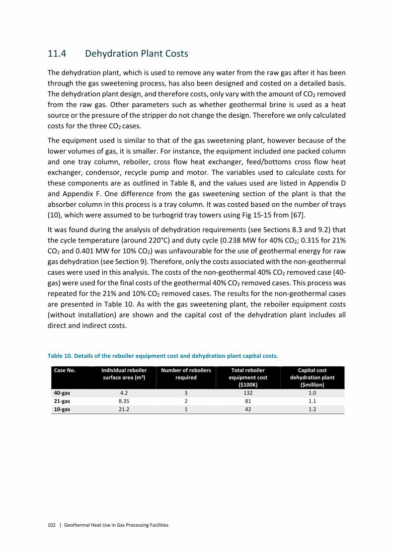
102 | Geothermal Heat Use in Gas Processing Facilities
11.4 Dehydration Plant Costs
The dehydration plant, which is used to remove any water from the raw gas after it has been through the gas sweetening process, has also been designed and costed on a detailed basis. The dehydration plant design, and therefore costs, only vary with the amount of CO2 removed from the raw gas. Other parameters such as whether geothermal brine is used as a heat source or the pressure of the stripper do not change the design. Therefore we only calculated costs for the three CO2 cases.
The equipment used is similar to that of the gas sweetening plant, however because of the lower volumes of gas, it is smaller. For instance, the equipment included one packed column and one tray column, reboiler, cross flow heat exchanger, feed/bottoms cross flow heat exchanger, condensor, recycle pump and motor. The variables used to calculate costs for these components are as outlined in Table 8, and the values used are listed in Appendix D and Appendix F. One difference from the gas sweetening section of the plant is that the absorber column in this process is a tray column. It was costed based on the number of trays (10), which were assumed to be turbogrid tray towers using Fig 15-15 from [67].
It was found during the analysis of dehydration requirements (see Sections 8.3 and 9.2) that the cycle temperature (around 220°C) and duty cycle (0.238 MW for 40% CO2; 0.315 for 21% CO2 and 0.401 MW for 10% CO2) was unfavourable for the use of geothermal energy for raw gas dehydration (see Section 9). Therefore, only the costs associated with the non-geothermal cases were used in this analysis. The costs of the non-geothermal 40% CO2 removed case (40-gas) were used for the final costs of the geothermal 40% CO2 removed cases. This process was repeated for the 21% and 10% CO2 removed cases. The results for the non-geothermal cases are presented in Table 10. As with the gas sweetening plant, the reboiler equipment costs (without installation) are shown and the capital cost of the dehydration plant includes all direct and indirect costs.
Table 10. Details of the reboiler equipment cost and dehydration plant capital costs.
Case No. Individual reboiler surface area (m3)
Number of reboilers required
Total reboiler equipment cost
($100K)
Capital cost dehydration plant
($million) 40-gas 4.2 3 132 1.0 21-gas 8.35 2 81 1.1 10-gas 21.2 1 42 1.2

Geothermal Heat Use in Gas Processing Facilities | 103
11.5 Total Gas Processing Plant Costs
The non-equipment direct and indirect costs were calculated as a fraction of the equipment cost [70] [67]. These fractions are shown in Table 11.
Table 11. Direct and indirect costs as a fraction of the equipment cost associated with the gas processing plant.
Direct costs Fraction of equipment cost Purchased equipment – delivered 1 Purchased equipment – installation 0.47 Instrumentation and controls 0.36 Piping 0.68 Electrical systems 0.11 Buildings 0.18 Yard improvements 0.1 Service facilities 0.7 Indirect costs Engineering and supervision 0.33 Construction expenses 0.41 Contractor’s fee 0.22 Contingency 0.48 Fixed capital investment (FCI) Direct + Indirect
The operating (O&M) costs were calculated on a variable (annual basis). The utility costs were calculated based on the electrical and water requirements of the gas processing plant equipment described in Appendix C. The remaining costs were calculated as either a fraction of the operating labour or a fraction of the Fixed Capital Investment (FCI) as shown in Table 12 [70] [67] [71]. The number of operating labour hours per year was based on the size of the plant, the number of independent processes (in this case, there is only 1), the fact that the process would be operating under average conditions and the expected operating days per year (333 days) (Fig 6-9 [67]). The hourly wage of $56.42/hour used is based on the mining industry average weekly pay and the average number of weekly hours worked by machinery operators [72]. The total operating costs, including geothermal, for each case are shown in Table 38 in Appendix I.
The ratio of the operating costs compared to capital costs may be higher than what would be expected for a commercially-operating gas processing plant. This is in part due to labour costs – it needs to be remembered that in this study we have not considered the whole of the capital required to build a working gas processing plant, but rather only the parts that are relevant for geothermal integration. However, the operating costs and the labour component in particular are those of an entire gas processing plant. In any case, when comparing the gas-only cases with the geothermal cases, the operating costs of the gas processing plant do not vary considerably.

104 | Geothermal Heat Use in Gas Processing Facilities
Table 12. Inclusions and their assumed costs as a fraction of either Operating (OL), Fraction of Capital Investment (FCI) or Maintenance costs.
Parameter Cost Operating labour (OL) $1.9 million/year Operating supervision 0.15 OL Utilities calculated Maintenance and repairs 0.06 FCI Operating supplies 0.15 Maintenance Laboratory charges 0.15 OL Total operating cost Sum of above

Geothermal Heat Use in Gas Processing Facilities | 105
12 Financial Assumptions
The levelised cost of CO2 removed has been calculated in this study. This refers to the removal of CO2 from the raw gas during the gas sweetening step. The amounts removed are the same for the geothermal and non-geothermal cases and only vary by the quantity of CO2 in the raw gas stream. However, the costs of removal are different for each case. The financial assumptions used are shown in Table 13 and the equation used is:
[0.4 × (1 + 𝑟𝑟)2 + 0.4 × (1 + 𝑟𝑟) + 0.2]𝑟𝑟 × (1 + 𝑟𝑟)𝐿𝐿
(1 + 𝑟𝑟)𝐿𝐿 − 1×
𝐾𝐾𝐶𝐶𝑂𝑂2
+𝑂𝑂&𝑀𝑀𝐶𝐶𝑂𝑂2
+ 𝐹𝐹𝐶𝐶𝑂𝑂2
+𝐶𝐶𝐶𝐶𝑂𝑂2
Where the values 0.4, 0.4 and 0.2 represent the share of capital cost paid over the three year construction period in years 1, 2 and 3 respectively; r is the discount rate, L is the amortisation period, K is the capital cost of the entire plant ($), O&M is the operating cost of the entire plant ($/year), CO2 is the amount of CO2 removed per year and F is the cost of gas burnt for fuel in the gas-only cases ($/year). C is the price paid for emissions ($/year) from the use of gas burnt for fuel in the gas-only cases, when a price is put on emissions in the later analysis. The first part of the equation in square brackets takes into account interest paid during construction.
Table 13. Financial assumptions used for calculating the levelised cost of CO2 removed.
Parameter Assumed value Discount rate 7.047% Amortisation period 30 years Construction period 3 years Share of capital cost paid in year 1 40% Share of capital cost paid in year 2 40% Share of capital cost paid in year 3 20%
12.1 Gas Prices
Gas prices in the Eastern Australian gas market (EAGM) were determined using the non-linear model developed by Wagner [73]. This model includes the impact of LNG exports with linkages to international (specifically Asian) gas markets and the impact of the current low oil prices with the international gas price. The model consists of agents (which are the producers), traders/marketers and consumers in the whole of the EAGM. The non-consumer agents maximise their profits in the model. Raw gas production costs, gas reserves and data on producers etc has been sourced from government reports and the literature by Wagner and included in the model.
Reference case oil price scenarios were run on the model and results presented for gas prices from all of hubs in the EAGM, such as Moomba and Curtis Island, for the years 2014 to 2050. The average across the EAGM and the maximum and minimum values per year based on the

106 | Geothermal Heat Use in Gas Processing Facilities
standard deviation (green range) are also shown in Figure 50. This provides a range of plausible prices a producer could expect to receive for their sales gas. This is not cost of production of gas, but the sales price at the hub. However, this would closely follow the cost of production and is valid for the assessment we are undertaking in this study.
Figure 50. Reference case projected gas prices for the EAGM derived from [73].
12.2 Carbon Pricing
While Australia no longer has a price on carbon, there are mechanisms for reducing CO2 emissions from industry such as the Emissions Reduction Fund (ERF), where industry is paid for reducing emissions. The value put on reducing emissions will be determined by reverse auction. In the current round the average price is $14/tCO2-e [74]. This is the price that can be paid to industry to undertake an initiative to reduce emissions, such as incorporating geothermal into a gas processing plant. This amount of money would be paid to the particular industry based on the amount of abatement produced from that process. However, it will only be paid for a nominated period of time and not over the life of the plant. This is the opposite of a carbon price where polluting industries pay a price to pollute; in the ERF polluting industries are paid to reduce their emissions. As the analysis in this report is focussed on single gas processing plants with and without geothermal and not a whole industry, it is valid to assume that the ERF could apply.
As there is a great deal of uncertainty about the actual value of the ERF into the future, a range of carbon prices as well as the ERF have been used in this analysis for comparing the levelised cost of CO2 removed using geothermal vs. using gas. This range is based on
0
2
4
6
8
10
12
14
16
2014 2019 2024 2029 2034 2039
Proj
ecte
d EA
GM
pric
es ($
/GJ)
Year
Average
Moomba
Curtis Island (LNG)

Geothermal Heat Use in Gas Processing Facilities | 107
projections of carbon prices globally as shown in Table 14 with interpolation used to calculate carbon prices for preceding, intervening and later years [75]. The resultant carbon price scenarios and ERF are shown in Figure 51. Because of the uncertainty surrounding the ERF it has been kept constant on a real basis in this study.
Table 14. Projected carbon prices from IEA scenarios in selected world regions and for various sectors ($/tCO2-e).
Scenario Region Sectors 2020 2030 2035
Current policies (CP) EU power industry and aviation
24 39 47
NZ All 24 39 47
Korea power and industry 24 39 47
New policies scenario (NP)
EU power industry and aviation
31 52 63
NZ All 31 52 63
Korea power and industry 31 52 63
China All 16 38 47
South Africa power and industry 13 24 31
450 scenario (450) US and Canada power and industry 31 149 197
EU power industry and aviation
55 149 197
Japan power and industry 31 149 197
Korea power and industry 55 149 197
NZ All 55 149 197
China, Russia, Brazil and south Africa
power and industry 16 110 157

108 | Geothermal Heat Use in Gas Processing Facilities
Figure 51. Carbon price scenarios.
0
50
100
150
200
250
300
2015 2020 2025 2030 2035 2040
Proj
ecte
d ca
rbon
pric
e ($
/tCO
2-e)
Year
Current policies
New policies
450ppm
ERF
Geothermal Heat Use in Gas Processing Facilities | 109
13 Methodology
The levelised cost of CO2 removed has been calculated using the capital and operating costs as described in previous sections. The cost of gas used for steam and the cost of emissions in the form of a price on carbon have been included for the gas-only cases. While in practice the application of the ERF would be used to reduce the levelised cost of the geothermal cases rather than increase the cost of the gas-only cases, in this study it has been used to increase the cost of the gas-only cases to make the comparison between all the different carbon pricing mechanisms on the same basis. Doing this does not impact on the absolute difference in levelised cost between the geothermal and gas-only cases but it does impact on the individual values.
The levelised cost of CO2 removed is a simple metric for comparing the costs of various types of plant. In this study, the levelised cost of the non-geothermal 40% CO2 removed case was compared with the 40% CO2 removed geothermal cases, and similarly for the 21% and 10% CO2 removed cases. The levelised cost determines the revenue that would be required for the producer to recover their expenses. Since the geothermal-based cases in this study have zero emissions and use no gas, they have an opportunity to generate more revenue than the non-geothermal cases. For further comparison because there is a great deal of uncertainty around the costs of geothermal wells, the well cost required for the geothermal cases to match the non-geothermal cases has been calculated under the carbon price and gas price scenarios examined.
To examine the sensitivity of various assumptions used in this analysis, each financial assumption and the capital and operating costs were altered independently by ±30% and the levelised cost calculations repeated. The percentage difference of each re-calculated levelised cost with the unaltered levelised cost is then plotted in a “Tornado chart” (e.g. Figure 58). The length of the bars in the chart is an indication of the impact each assumption has on the levelised cost and thus the sensivity of the levelised cost to each assumption.

110 | Geothermal Heat Use in Gas Processing Facilities
14 Results and Discussion
14.1 Levelised Cost of CO2 Removed
The levelised cost of CO2 removed with 40%, 21% and 10% CO2 in the raw natural gas for each case is shown in Figure 52, Figure 53 and Figure 54 respectively. The contribution of gas processing plant capital, geothermal capital and gas processing and geothermal operating costs to the levelised cost is shown. In the gas-only cases the impact of the cost of gas used as fuel is also shown under various gas price trajectories. These figures do not include a price on emissions. The blue horizontal lines in the figures indicate the lowest-cost geothermal case for that particular amount of CO2 removed.
It can be seen that the geothermal plants are more expensive when compared with a gas-only plant with an average gas fuel price. However, the difference is not great as can be seen in Table 15 where the difference between the two lowest-cost geothermal plants under each CO2 removed scenario and the gas-only plants are shown. The differences in levelised cost are of course greater when the minimal and Moomba gas price trajectories are used. However, under the Curtis Island gas price trajectories several geothermal 10% and 40% CO2 removed cases have a lower levelised cost than the gas-only cases, as can be seen in Table 15.
Table 15. Difference in levelised cost between lowest-cost geothermal and gas-only cases. A negative number indicates that geothermal has a lower levelised cost.
Geothermal cases Gas only cases Average gas price ($/tCO2 rem)
Maximum gas price ($/tCO2 rem)
Curtis Is gas price ($/tCO2 rem)
40-200-1 40-gas 3.5 0.6 -0.8 40-200-0.8 40-gas 2.9 0 -1.4 21-200-1 21-gas 5.4 2.8 1.5 21-200-0.8 21-gas 5.0 2.4 1.1 10-200-1 10-gas 3.8 0.6 -1 10-200-0.8 10-gas 4.0 0.7 -0.9
Operating and fuel costs dominate the cost of all gas-only plants, as can be seen in the figures. In the geothermal cases the geothermal capital cost is the dominant factor, however in the 10% cases the gas processing plant operating cost also makes a significant contribution. The geothermal capital contribution is greater when there is more CO2 in the raw gas, as greater amounts of geothermal brine are required which means more wells and a higher capital cost. The lowest-cost geothermal cases are shown in Table 15, which correspond to brine temperatures of 200°C and column pressures of 1 and 0.8 bar. A summary of these levelised costs can be seen in Table 16. The levelised cost increases as the amount of CO2 to be removed decreases. This is because the denominator in the levelised cost equation – CO2 – is lower and the dominant plant costs such as geothermal capital cost do not scale linearly with size.

Geothermal Heat Use in Gas Processing Facilities | 111
Figure 52. Projected levelised cost of CO2 removed for the cases with 40% CO2 in the raw gas. Case numbers are shown on the x-axis.
Figure 53. Projected levelised cost of CO2 removed for the cases with 21% CO2 in the raw gas. Case numbers are shown on the x-axis.
0
10
20
30
40
50
60
70
80
90
100Pr
ojec
ted
leve
lised
cost
of C
O2
rem
oved
($/t
CO2)
Gas plant capital Gas plant O&M Gas fuel Geothermal O&M Geothermal capital
0
10
20
30
40
50
60
70
80
90
100
Proj
ecte
d le
velis
ed co
st o
f CO
2 re
mov
ed ($
/tCO
2)
Gas plant capital Gas plant O&M Gas fuel Geothermal O&M Geothermal capital

112 | Geothermal Heat Use in Gas Processing Facilities
Figure 54. Projected levelised cost of CO2 removed for the cases with 10% CO2 in the raw gas. Case numbers are shown on the x-axis.
Table 16. Summary of levelised costs of lowest-cost geothermal cases.
Geothermal cases Levelised cost ($/tCO2 removed)
40-200-1 27.0 40-200-0.8 26.4 21-200-1 30.9
21-200-0.8 30.5 10-200-1 45.9
10-200-0.8 46.0
The impact of a carbon price on the levelised cost with an average gas price can be seen in Figure 55, Figure 56 and Figure 57 with 40%, 21% and 10% CO2 in the raw gas respectively. The blue line again indicates the lowest-cost geothermal case. The inclusion of a carbon price has decreased the difference between the geothermal and gas-only cases more than changes to the gas price trajectory had. Under the 450 ppm (450) scenario, the lowest-cost geothermal cases are clearly cheaper than the gas only cases. Under the New Policies (NP) scenario the two lowest-cost 40% and 10% geothermal cases almost match the gas-only cases. The ERF and Current Policies (CP) are not high enough for geothermal to be competitive. However, the difference is still not great as can be seen in Table 17.
0
10
20
30
40
50
60
70
80
90
100Pr
ojec
ted
leve
lised
cost
of C
O2
rem
oved
($/t
CO2)
Gas plant capital Gas plant O&M Gas fuel Geothermal O&M Geothermal capital

Geothermal Heat Use in Gas Processing Facilities | 113
Figure 55. Projected levelised cost of CO2 removed for the cases with 40% CO2 in the raw gas and under carbon price scenarios. Case numbers are shown on the x-axis. The dark blue represents the effect of a carbon price.
Figure 56. Projected levelised cost of CO2 removed for the cases with 21% CO2 in the raw gas and under carbon price scenarios. Case numbers are shown on the x-axis. The dark blue represents the effect of a carbon price.
0
10
20
30
40
50
60
70
80
90
100Pr
ojec
ted
leve
lised
cost
of C
O2
rem
oved
($/t
CO2)
Gas plant capital Gas plant O&M Gas fuel
Geothermal O&M Geothermal capital Lowest cost geothermal
0
10
20
30
40
50
60
70
80
90
100
Proj
ecte
d le
velis
ed co
st o
f CO
2re
mov
ed ($
/tCO
2)
Gas plant capital Gas plant O&M Gas fuel
Geothermal O&M Geothermal capital Lowest cost geothermal
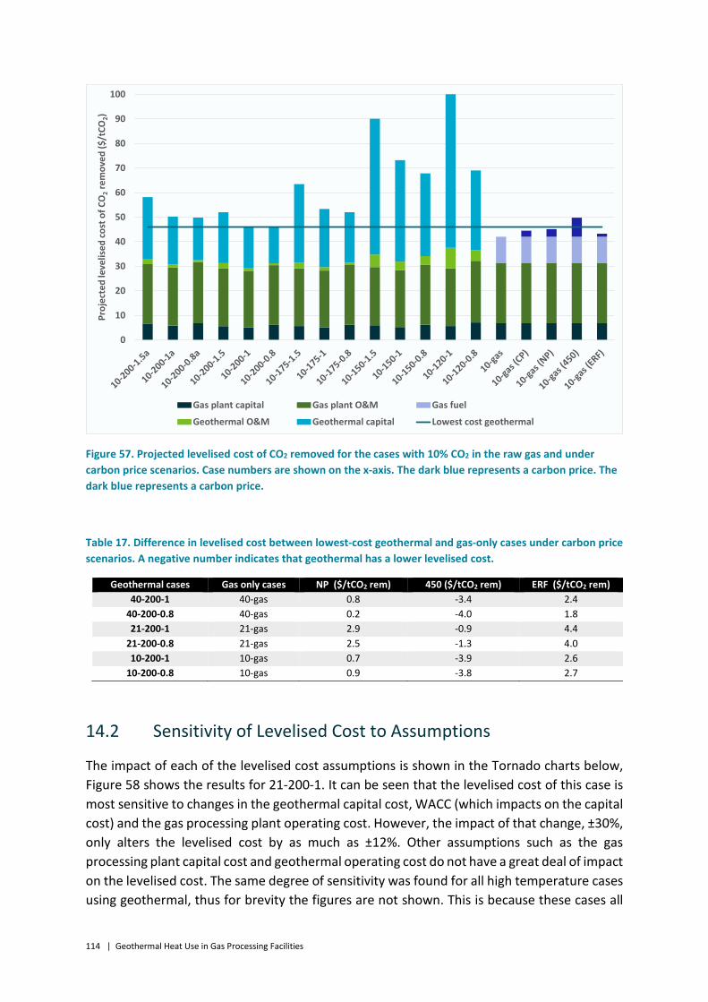
114 | Geothermal Heat Use in Gas Processing Facilities
Figure 57. Projected levelised cost of CO2 removed for the cases with 10% CO2 in the raw gas and under carbon price scenarios. Case numbers are shown on the x-axis. The dark blue represents a carbon price. The dark blue represents a carbon price.
Table 17. Difference in levelised cost between lowest-cost geothermal and gas-only cases under carbon price scenarios. A negative number indicates that geothermal has a lower levelised cost.
Geothermal cases Gas only cases NP ($/tCO2 rem) 450 ($/tCO2 rem) ERF ($/tCO2 rem) 40-200-1 40-gas 0.8 -3.4 2.4
40-200-0.8 40-gas 0.2 -4.0 1.8 21-200-1 21-gas 2.9 -0.9 4.4
21-200-0.8 21-gas 2.5 -1.3 4.0 10-200-1 10-gas 0.7 -3.9 2.6
10-200-0.8 10-gas 0.9 -3.8 2.7
14.2 Sensitivity of Levelised Cost to Assumptions
The impact of each of the levelised cost assumptions is shown in the Tornado charts below, Figure 58 shows the results for 21-200-1. It can be seen that the levelised cost of this case is most sensitive to changes in the geothermal capital cost, WACC (which impacts on the capital cost) and the gas processing plant operating cost. However, the impact of that change, ±30%, only alters the levelised cost by as much as ±12%. Other assumptions such as the gas processing plant capital cost and geothermal operating cost do not have a great deal of impact on the levelised cost. The same degree of sensitivity was found for all high temperature cases using geothermal, thus for brevity the figures are not shown. This is because these cases all
0
10
20
30
40
50
60
70
80
90
100Pr
ojec
ted
leve
lised
cost
of C
O2
rem
oved
($/t
CO2)
Gas plant capital Gas plant O&M Gas fuel
Geothermal O&M Geothermal capital Lowest cost geothermal

Geothermal Heat Use in Gas Processing Facilities | 115
have similar cost ratios, where the dominant costs are the geothermal capital and gas processing plant operating costs.
Figure 58. Tornado chart of levelised cost of case 21-200-1. The value of each parameter is either increased (green) or decreased (blue) and the resultant percentage change in levelised cost is shown on the x axis.
The results are different under the low temperature scenarios, as can be seen in Figure 59. Again for brevity only one case (21-120-1) is shown however, all low temperature cases have similar sensitivities. The changes to the geothermal capital cost and WACC (which impacts capital cost) have a large impact on the levelised cost; a ±30% change alters the levelised cost by up to ±22%. This is because of the high number of wells that need to be drilled in the low temperature cases, which increase the capital cost of geothermal substantially over the other costs. The gas processing plant costs in all cases are very similar, thus an increase geothermal costs decreases the relative contribution of the “fixed” gas processing plant costs to the levelised cost.
-25% -20% -15% -10% -5% 0% 5% 10% 15% 20% 25%
Gas processing plant O&M
Geothermal O&M
WACC
Amortisation period
Gas processing plant capital cost
Geothermal capital cost
lower base higher

116 | Geothermal Heat Use in Gas Processing Facilities
Figure 59. Tornado chart of levelised cost of case 21-120-1. The value of each parameter is either increased (green) or decreased (blue) and the resultant percentage change in levelised cost is shown on the x axis.
The tornado chart of a gas-only case is shown in Figure 60. All gas-only cases have similar sensitivities thus only one is shown for brevity. As there are no large capital cost components in the gas-only plants the assumptions that have the greatest impact on levelised cost are the fuel cost and the gas processing plant operating costs. A ±30% change to the operating cost alters the levelised cost by ±15% and the same change to the fuel cost alters the levelised cost by ±10%. This sensitivity to the fuel cost could have an impact on the economics of gas-only gas processing plants in regions where there is a high fuel cost, such as in new gas field developments. A large change in gas price could make geothermal more affordable as an option for gas processing compared to the use of gas.
The tornado chart analysis shows that in order to reduce the levelised cost, efforts should be focussed on reducing the capital cost of geothermal, reducing financing costs and the operating cost of the gas processing plant. The largest contributors to the capital cost of geothermal are the well costs, and in the case of the operating cost it is labour and utilities.
-25% -20% -15% -10% -5% 0% 5% 10% 15% 20% 25%
Gas processing plant O&M
Geothermal O&M
WACC
Amortisation period
Gas processing plant capital cost
Geothermal capital cost
lower base higher

Geothermal Heat Use in Gas Processing Facilities | 117
Figure 60. Tornado chart of levelised cost of case 21-gas. The value of each parameter is either increased (green) or decreased (blue) and the resultant percentage change in levelised cost is shown on the x axis.
If in the future strong binding global climate targets are reached to reduce emissions there may be a high carbon price, such as the 450 ppm scenario, along with high gas prices. Demand for gas is expected to increase in the early stages of strong climate action, as gas is seen as a transition fuel from coal. Therefore, the impact of the highest carbon price trajectory and the highest gas price trajectory on the levelised cost of the gas-only cases is shown in Figure 61 along with the geothermal cases identified as having the lowest levelised cost. The figure shows that geothermal is lower in cost than gas-only by approximately $6/tCO2 (on a CO2 removed basis) in all cases. This is about the same as the impact of the carbon price i.e. the use of geothermal is offset by the carbon price.
-25% -20% -15% -10% -5% 0% 5% 10% 15% 20% 25%
Fuel cost
Gas processing plant O&M
WACC
Amortisation period
Gas processing plant capital cost
lower base higher

118 | Geothermal Heat Use in Gas Processing Facilities
Figure 61. Levelised costs of lowest-cost geothermal cases compared to highest-cost gas-only cases.
0
10
20
30
40
50
60
40-200-1 40-200-0.8
40-gas 20-200-1 20-200-0.8
20-gas 10-200-1 10-200-0.8
10-gas
Proj
ecte
d le
velis
ed co
st o
f CO
2re
mov
ed ($
/tCO
2)
Gas plant capital Gas plant O&M Geothermal O&M Geothermal capital Max gas 450 ppm

Geothermal Heat Use in Gas Processing Facilities | 119
14.3 Strategies for Equalising the Difference between Geothermal and Non-Geothermal Levelised Costs
Besides the strong level of climate action case described in the previous section it is useful to examine the combinations of carbon price and gas price that can equalise the levelised cost between the geothermal and gas-only cases. This has been determined by assuming a constant real gas price trajectory and then calculating the constant real carbon price trajectory required for the geothermal levelised cost to equal the non-geothermal levelised cost. This calculation has been undertaken only for the 1 bar lowest-cost geothermal cases, noting that the results are similar for the 0.8 bar matching cases. The results are shown in Table 18.
Table 18. Combinations of gas and carbon price required to remove levelised cost differences.
Gas price ($/GJ) 40-200-1 CO2 price ($/tCO2-e)
20-100-1 CO2 price ($/tCO2-e)
110-200-1 CO2 price ($/tCO2-e)
1 153 185 151 2 132 164 130 3 111 143 109 4 90 122 88 5 68 101 67 6 47 80 46 7 26 59 25 8 5 37 4 9 -16 16 -18
10 -37 -5 -39
It can be seen that at higher gas prices such as $9-10/GJ, the required carbon price is negative, which means that geothermal is lower in cost than using gas-only. At a lower gas price of $4/GJ (which is similar to the Moomba gas price trajectory), the required carbon price is $88-122t/CO2-e depending on the particular case. At a gas price of $6/GJ, which was the typical price across the EAGM in recent years, the carbon price required for the 10% and 40% cases is ~$25/tCO2-e. This is equivalent to the 2020 carbon price assumed in the Current Policies scenario (Table 14) and is an entirely plausible medium-term scenario.
Besides adjusting for carbon and gas price, there is a great deal of uncertainty surrounding geothermal well costs in particular. Studies of the oil and gas industry have found that well drilling costs can be reduced by as much as 20% for every doubling in the number of wells drilled using the same crew and at the same location [63]. In this analysis cost reductions due to learning by doing have not been included because the well costs used are an average cost, which may take some small learning into account. The difference in levelised costs when drilling is assumed to have a 20% learning rate is shown in Figure 62 for the 20% cases.

120 | Geothermal Heat Use in Gas Processing Facilities
Figure 62. Levelised cost of 20% cases with and without technology learning on drilling.
The difference is only significant for the lower temperature cases, where the number of wells drilled is quite high. This is because the costs reduce for each subsequent well, thus as more wells are drilled the cost per well reduces even further.
There is also a great deal of uncertainty around flow rates from geothermal wells. The costings conducted in this study are based on somewhat favourable flow rates per well (80-100 kg/s per well). These flow rates have not been achieved in the resources with the required temperatures in Australia to date. If the flow rates are lower, more wells need to be drilled which can have a large impact on the capital cost. Similarly, if the well costs are higher (or lower) then this will also have a strong effect on the economic viability of using geothermal heat.
In order to explore the uncertainty surrounding well costs, the geothermal capital cost required for the lowest-cost geothermal cases to equal the gas-only cases has been calculated using the average gas price trajectory. The results are shown in Table 19. The results are quite sensitive to carbon price scenario. Under the no-carbon price scenario geothermal well costs need to reduce by a minimum of 23% (case 10-200-1) and a maximum of 41% (case 20-200-1) for the geothermal case levelised cost to equal the gas-only case. Under the 450 ppm scenario geothermal costs can actually be higher than what has been assumed; a minimum of 7% higher (case 20-200-1) and a maximum of 29% higher (case 40-200-1).
0
20
40
60
80
100
120Pr
ojec
ted
leve
lised
cost
of C
O2
rem
oved
($/t
CO2)
Learning on wells No learning on wells

Geothermal Heat Use in Gas Processing Facilities | 121
Table 19. Analysis of required geothermal capital cost reduction in order to equal non-geothermal cost. A negative difference (as in the 450 ppm scenarios) means that the geothermal option costs less than the non-geothermal option without reducing the geothermal capital costs.
Case No Carbon price scenario
Amount capital needed to reduce
by ($million)
Current geothermal capital cost ($million)
Required geothermal capital cost ($million)
Difference (%)
40-200-1 None 31.4 103.9 72.5 30% Current policies 12.2 91.7 12% New policies 6.9 97 7% 450 ppm -30.0 133.9 -29% ERF 21.8 82.1 21%
20-200-1 None 24.1 58.6 34.5 41% Current policies 15.3 43.3 26% New policies 12.9 45.7 22% 450 ppm -3.9 62.5 -7% ERF 19.7 38.9 34%
10-200-1 None 7.2 30.9 23.7 23% Current policies 2.6 28.3 8% New policies 1.4 29.5 5% 450 ppm -7.4 38.3 -24% ERF 4.9 26.0 16%
The information presented in Table 19 can be used to further examine the relationship between flow rate and drilling costs for the various scenarios presented. The target cost of accessing the brine in $/kg can be calculated by dividing the drilling component of the required geothermal capital costs in Table 19 by the required overall flow rate (double the total brine flow rate to account for the fact that the productions injection wells each need to carry the total flow). For these calculations we have assumed that 80% of the required geothermal capital cost will be drilling costs. This data can then be plotted on a chart of drilling cost versus flow rate and the line represents the break-even point for the geothermal scenarios with the non-geothermal scenarios. The results are presented in Figure 63. Figure 64 shows the effect of geothermal resource temperature. In these plots, flow rates that fall above a line for a given well cost are more favourable for the geothermal option. For example, in Figure 63, if the average well cost was $20 million per well and the average flow rate was over 75 kg/s per well, the geothermal option would have a lower cost than the non-geothermal option. On the other hand, if the average flow rate was 40 kg/s per well, then the geothermal option would only have a lower cost in the 450 ppm carbon price scenario.
Figure 65 provides a summary of the relative importance of the temperature of the geothermal resource and carbon pricing, along with flow rate and well cost. The gas price will also be important and will act in a similar way to a carbon price (see Table 18). Geodynamics’ Habanero project is Australia’s most technically successful geothermal project, with a resource temperature of over 210°C with a maximum flow rate of 40 kg/s from the Habanero 4 well [13]. Depending on the CO2 concentration of the raw gas feed, this would require a well cost of between $10 million and $15 million if there is no price on carbon and with an average gas price. These drilling costs are significantly lower than the costs used in

122 | Geothermal Heat Use in Gas Processing Facilities
this study. It also highlights the technical challenges around improved flow rates and decreased drilling costs highlighted in the IGEG study of power generation from geothermal power stations [52].
Figure 63. Relationship between per well flow rate and well cost showing the influence of various carbon pricing scenarios for a feed gas with 21% CO2. The geothermal option is equal or lower cost compared to the gas only case for flow/drilling cost combinations that plot on or above the line for each scenario. The above graph is for the data presented in Table 19.

Geothermal Heat Use in Gas Processing Facilities | 123
Figure 64. Relationship between per well flow rate and well cost showing the effect of geothermal resource temperature and with no-carbon price. The lower CO2 scenarios with 120 °C brine do not plot on this chart as their slope is too steep. This chart clearly shows the importance of resource temperature.

124 | Geothermal Heat Use in Gas Processing Facilities
Figure 65. Relationship between per well flow rate and well cost showing the effect of geothermal resource temperature and a no carbon price scenario, a carbon price equivalent to the current Emissions Reduction Fund, and the moderate carbon price scenario (New Policy) for a feed gas with 21% CO2.

Geothermal Heat Use in Gas Processing Facilities | 125
Part V Conclusions and Future Work

126 | Geothermal Heat Use in Gas Processing Facilities
15 Conclusions
Natural gas is an important resource for Australia, both as a domestic energy resource and as an export commodity. Exports of LNG are forecast to increase by four to five times from current levels by the end of the decade [19], with Australia expected to become the world’s largest exporter of LNG. Export revenue is forecast to exceed $50 billion per annum [76]. Australia’s gas sector consumes approximately 8 to 10% of the gas produced – the equivalent of the output of one large LNG facility – for the processing of gas. If this energy for processing could be sourced from alternatives to gas, then additional supply for domestic consumption and export would be available.
This study has attempted to understand the feasibility of using geothermal heat in gas processing plants to offset the use of potential sales gas within those facilities. The use of geothermal energy to provide energy for process heat could be desirable if it reduces costs, increases the amount of gas available for sale, or helps to mitigate a future carbon price. Using geothermal energy in direct use applications may provide a more effective use of this resource as it avoids the relatively low conversion efficiencies associated with converting the low grade heat in geothermal resources in to electricity.
Natural Gas Resources
Australia has large conventional gas and coal seam gas resources that are reasonably well defined along with significant potential for unconventional gas resources that have not been as well tested. The specifications for gas to be sold to domestic markets or used for LNG production for export are well understood and reasonably consistent. However, the composition of raw gas in situ in Australia is highly variable at basin scale. It is difficult to obtain data on the raw gas compositions produced from the various basins in Australia or the feed gas composition of existing gas processing facilities. While gas analyses conducted during exploration have to be reported, production test data and detailed gas analysis does not. This information is considered commercially sensitive and is rarely published.
While some basins show higher degrees of maturity than others, all basins have gas accumulations that have high concentrations of impurities such as CO2, H2S and N2 that will need to be removed if that gas is to be brought to market. Processing to separate NGL’s and condensate from gas will also be required in many instances, and dehydration is a ubiquitous requirement. LNG plants have lower tolerance to water, CO2 and condensing hydrocarbon content as these components would cause problems during the liquefaction processes.
It is worth noting that LNG for domestic consumption may provide a demand for higher levels of gas processing in Australia. The large LNG export facilities are located on the coast to facilitate shipment, and may not be near suitable geothermal resources. LNG produced for domestic consumption via the virtual pipeline approach (where the pipeline is substituted by

Geothermal Heat Use in Gas Processing Facilities | 127
containerised distribution of LNG) could be conducted closer to the gas and/or geothermal resource. A study of LNG processes was not a part of the scope of this study.
Geothermal Resources
Australia’s geothermal resources are not as well defined as its gas resources. While the temperature distribution is reasonably well understood in the basins that have seen significant amounts of oil and gas exploration, information on permeability at depth, or the existence of conditions favourable to the enhancement of permeability, is not readily available. The highest geothermal gradients seen in Australia are in the Nappamerri Trough in the Cooper Basin. This heat resource is the target of Geodynamics Ltd’s Innamincka Deeps Project. Elevated geothermal gradients are also observed in most of Australia’s other hydrocarbon producing basins including the Gippsland, Otway, North Perth and onshore Carnarvon Basin. Locally elevated thermal gradients are also observed in the Surat Basin.
Within each sedimentary basin, there are local heat anomalies that result from heterogeneities in the geology at the kilometre to tens of kilometre scale. Detailed exploration would be required to identify the most prospective geothermal targets. Data collected as part of exploration for oil and gas could be used if added emphasis was placed on collecting appropriate data (temperature logs, thermal conductivities, geomechanical properties). New build gas processing facilities could be located on or near these resources as it is easier to move gas to a processing plant than heat to a gas plant.
Australia’s geothermal resources are relatively unproven. This study has assumed flow rates of 100 kg/s for natural reservoirs and 80 kg/s for EGS resources. These flow rates are yet to be demonstrated in Australia. This highlights one of the key challenges for geothermal heat utilisation for industrial process heat in Australia, and that is demonstrating that the required flow rates can be achieved, and reducing the risks in discovering geothermal resources.
Integration of Geothermal Heat in Australian Gas Processing Plants
The two major energy requirements in a 125 MMscfd gas processing plant in an Australian context were identified as the reboiler duties for the gas sweetening and gas dehydration steps. These major heat requirements could be met with geothermal heat for low, medium and high CO2 inlet gas conditions. Compression and refrigeration were not considered in the report as it is deemed a poor match for geothermal heat.
Integration with geothermal heat results in much larger reboiler surface areas when compared with steam as the heating source. This results in increased capital cost due to larger or multiple reboilers. Methyl diethanolamine (MDEA) based sweetening processes were found to be the most suitable for gas sweetening with geothermal heat across a range of CO2 concentrations. Higher brine inlet temperatures favour higher thermal driving forces and lower reboiler surface areas. Calculations have included inlet temperatures of 200°C for the gas sweetening step. However it is recommended to limit the brine inlet temperature to the sweetening step reboiler to 175°C to prevent MDEA degradation. A working fluid could be

128 | Geothermal Heat Use in Gas Processing Facilities
considered if significantly higher brine temperatures are available. However other considerations, such as increased heat transfer area and additional equipment need to be assessed.
Operation at slightly vacuum conditions favours lower brine reinjection temperatures and hence better utilisation of the geothermal heat. However, potential air ingress into a natural gas environment requires significant safety considerations, and extra capital outlay is required for a vacuum pump.
To meet the required heat duties 1-3 production wells for 175°C brine or 1-6 production wells for 150°C brine are required. The duty of the dehydration step reboiler is two orders of magnitude lower than the sweetening step reboiler duty and as a result only up to 21 kg/s of 220-240°C brine would be required. It is very likely that the costs associated with drilling a production well for this supply would far outweigh the advantages of replacing the steam to the gas dehydration reboiler with geothermal heat.
In an Australian context, based on the raw natural gas assumptions in this report and in the absence of a techno-economic analysis, utilising geothermal heat for the gas dehydration step is not warranted, unless a source of high temperature brine already exists. In this scenario, it is suggested that a separate supply of geothermal brine, at the required temperature is utilised for the gas sweetening and gas dehydration reboilers. The heat requirements for the gas dehydration reboiler are nonetheless very low in comparison with gas sweetening reboiler and it is further suggested that the best gains can be made by focussing solely on the gas sweetening reboiler.
In an Australian context, geothermal heat is best matched with the gas sweetening step, as the high reboiler duties allow for a good match with flow rates anticipated from geothermal resources. The largest geothermal brine flows are required for CO2 inlet gas concentrations of 40%. At this high inlet concentration it is estimated that energy savings of up to 5% of the sales natural gas can be made. However, compromises may need to be made between operating cost savings and the increased capital cost required when integrating geothermal heat into a gas processing plant.
This study has found that the use of geothermal energy in the gas sweetening step is technically feasible and that integrating geothermal heat directly at the reboiler can readily be done, unless there are concerns for scaling or corrosion. The integration with geothermal heat would reduce the self-consumption of gas if no other heat source is available. No major above ground technical barriers are envisaged, and integration would be determined based the economics and the below-ground challenges.

Geothermal Heat Use in Gas Processing Facilities | 129
Economic Evaluation
A 125 MMscfd gas processing plant was evaluated in this study. A comparison of the economics of utilising geothermal heat in gas processing plants against the use of gas to supply heat found that the costs are comparable within the level of accuracy of this study. This finding indicates that the use of geothermal heat in a processing plant warrants more detailed consideration on a case-by-case basis. A higher gas price or the introduction of a carbon price would further enhance the economics of the geothermal option.
The scale of operation investigated in this report (125 MMscfd) is relatively small compared to standard gas processing plants, for instance, Moomba. If the plant in this study was scaled up, the capital costs per unit of output would decrease due to economies of scale. Also the geothermal wells would be better utilised and, as many wells would need to be drilled to increase the amount of brine, cost reductions in drilling may be observed due to learning by doing.
The reinjection temperature has been fixed at 10°C above the reboiler temperature in this study. Given the relative differences in expected higher capital cost of geothermal brine vs. a reboiler, it would be advantageous to reduce the brine flow rate and increase the size of the reboiler (i.e. operate with a low approach temperature).
The CO2 removed in the sweetening step is in a concentrated form making it a good candidate for sequestration. If integration with geothermal heat required a high carbon price to be attractive, then CO2 sequestration may also be attractive to reduce the overall carbon price liability. However, lowering the stripper pressure, may negatively impact the economics when CO2 sequestration is required as the stream exits the stripper at a low pressure (0.8-1.5 bar,a) and consequently requires higher compression to the required sequestration pressure.
The economic results were found to be most sensitive to geothermal capital costs, gas fuel costs and gas processing plant operating costs. There is a great deal of uncertainty around geothermal field costs and well flow rates. To deal with this uncertainty, we have considered what the geothermal field costs would have to be to allow the geothermal option to be competitive with the base case (non-geothermal) for a range of resource temperatures.
Final Comments
For the cases investigated, geothermal heat is well matched to supply the heat duty in the gas sweetening step of an Australian gas processing plant, particularly in scenarios allowing lower reboiler operating temperatures and natural gas streams with high CO2 concentration. The economic evaluation results show that integration of geothermal heat is competitive with the gas-only options, but only with geothermal resources at the higher end of the temperature scale.

130 | Geothermal Heat Use in Gas Processing Facilities
16 Future Work
During the course of this study we have identified many areas for future research that would allow a better understanding of the potential use of geothermal energy in gas processing plants and the efficient use of energy in gas processing plants in general.
This study did not consider the combination of geothermal energy with other sources of heat, such as a dedicated gas-fired boilers or waste heat recovery units, within a gas processing facility. Nor did it consider the implications of using electrical power generated outside of the gas processing plant and the implications for the supply of heat within the facility (where waste heat was not available). An economic study of the implications for capital expenditure versus operating expenditure would also be required. This electrical power could simply be for the existing electrical energy requirements in gas processing plants or be used to replace gas turbine driven compression units (compression used for pipeline delivery in domestic markets, refrigerant compression in NGL removal or in LNG facilities). A detailed study of these aspects could be considered the logical next stage of the work presented here.
For raw gas with high CO2 concentrations, a multistage approach involving membranes for the removal of bulk CO2 followed by a solvent based stage for the removal of the remaining CO2 may produce a more efficient process overall. Optimisation studies of the combination of these two processes to minimise both capital and operating costs would confirm the potential efficiency improvements of such a system.
This study has focused on the use of geothermal heat in gas processing facilities. A similar study to investigate the use of solar thermal heat is also recommended. Such a study could easily build on the work conducted here as the processes within the plant would be very similar - it is primarily the heat source and its associated costs that change. The distribution of solar resources in Australia would need to be addressed as would the different solar thermal technologies (e.g. parabolic troughs versus solar tower). The intermittent nature of solar thermal would have to be considered and a combined solar thermal/gas-fired boiler approach would likely be required. Solar thermal may be useful where LNG facilities need to be built with access to port facilities as a primary consideration rather than the need to co- locate the facility with a good geothermal resource.
Considerable uncertainty still remains around the technical challenges in extracting geothermal resources in Australia. While this study does show a potential commercially viable application for geothermal energy in Australia, that viability is contingent on the ability of geothermal wells in Australia being able to deliver the flow rates required given the costs of developing such resources. Development of the technologies required to achieve these flow rates is an ongoing need for the geothermal sector in Australia. Techniques for characterising geothermal resources, potentially maximising the data are available from oil and gas exploration, would also help to reduce the risks around developing geothermal energy. We

Geothermal Heat Use in Gas Processing Facilities | 131
have not considered the effects of thermal draw down (cooling of the geothermal reservoir due to production) and this would also need to be investigated.
Some of the economic scenarios considered in this study assume a carbon price will be introduced in the future. This may increase the economic imperative to capture and store CO2 emissions from the gas processing plant. Where there is a significant amount of CO2 in the feed gas, the CO2 would need to be compressed for reinjection into a storage reservoir. An optimisation study of the design of the gas sweetening process using geothermal energy as a heat source with compression requirements for sequestration of the captured CO2 would allow the interaction of these processes to be investigated. There may even be potential to use the CO2 as a reservoir fluid for enhanced geothermal systems. This approach is attractive because of the higher transmissivity of CO2 due to its low viscosity. Research on this topic should be monitored if it becomes technically and commercially viable.
This study focused on the use of geothermal energy and gas processing plants in the Australian context. There may be value in conducting similar studies for other regions particularly those where conventional convective geothermal resources exist within pipeline distance of gas resources. An example could be the United States of America which has significant gas resources that may be suitable for export and well understood geothermal resources.
132 | Geothermal Heat Use in Gas Processing Facilities
17 Notation
450 450 ppm scenario
bar,a Absolute pressure in bar (i.e. gauge pressure + 1.01325 bar)
C2 / C2H6 Ethane
CO2 Carbon dioxide
COS Carbonyl sulphide
CP Current Policies
CS Carbon steel
CS2 Carbon disulphide
CSG Coal seam gas
DEA Diethanolamine
DEG Diethylene glycol
EAGM Eastern Australian gas market
EDR Economic Demonstrated Resource
EGS Enhanced (or Engineered) Geothermal Systems
ERF Emissions Reduction Fund
GJ Gigajoule
Hg Mercury
Hp Horsepower
H2S Hydrogen sulphide
HSA Hot Sedimentary Aquifers
kPa Kilo Pascals
LNG Liquefied natural gas
MDEA Methyl diethanolamine
MEA Ethanolamine
MMscfd Million standard cubic feet per day of gas flow
Mtpa Mega (million) tonnes per annum
MWe Mega Watt electrical
MWh Mega Watt hour
MWth Mega Watt thermal
N2 Nitrogen
NGL Natural gas liquid
NP New Policies

Geothermal Heat Use in Gas Processing Facilities | 133
O&M Operations and maintenance
ppm Concentration in parts per million
PJ Peta Joules (1x10¹⁵ Joules)
PZMDEA A solvent blend of MDEA with piperazine as rate promoter
SDR Sub-economic Demonstrated Resource
SS Stainless steel
tcf trillion standard cubic feet
TEG Triethylene glycol
TJ Tera Joules (1x10¹² Joules)
TJ/day Tera Joules per day (a common unit for gas production or consumption)
tpa Tonnes per annum
TREG Tetraethylene glycol
USD United States Dollars
WACC Weighted Average Cost of Capital

134 | Geothermal Heat Use in Gas Processing Facilities
18 References
[1] IEA, “World Energy Outlook 2014,” International Energy Agency, Paris, 2014.
[2] R. McDonough, “Chapter 4: Infrastructure,” in Petroleum Geology of South Australia, D. Gravestock, J. Hibburt and J. Drexel, Eds., Adelaide, South Australia Department of Primary Industries and Resources, 1998, p. Volume 4.
[3] Evans & Peck, “Competitive Role of Geothermal Energy near Hydrocarbon Fields,” Australian Renewable Energy Agency, Australia, 2014.
[4] M. Soltyk, “Gas Exchangeability in Western Australia: Gas Quality Specifications of Interconnected Pipeline Systems,” Economic Regulation Authority, Perth WA, 2007.
[5] Standards Australia, “AS 4564-2011 Australian Standard - Specification for General Purpose Natural Gas,” Council of Standards Australia, Sydney NSW, 2011.
[6] D. Coyle, F. de la Vega and C. Durr, “Natural Gas Specification Challenges in the LNG Industry. Paper PS4-7,” KBR, Houston TX, 2007.
[7] Worley Parsons, “CCS Learning from the LNG Sector: A Report for the Global CCS Institute,” Global CCS Institute, 401010-01060-00-PM-REP-0001, Melbourne VIC, 2013.
[8] Newpoint Gas, “FLNG / LNG Liquefaction Plants Gas Pre-Treatment Systems,” Newpoint Gas, 31 12 2010. [Online]. Available: http://www.newpointgas.com/LNG_Liquefaction_Plants.php. [Accessed 2 July 2015].
[9] G. R. Beardsmore and J. Cull, “Crustal heat flow; a guide to measurement and modelling,” Cambridge, UK, 2001.
[10] R. Hillis and S. Reynolds, “The Australian Stress Map,” Journal of the Geological Society, vol. 157, no. 5, pp. 915-921, 2000.
[11] Geoscience Australia and BREE, “Australian Energy Resource Assessment, 2nd Edition,” Geoscience Australia and BREE, Canberra, 2014.
[12] G. J. Beardsmore, A. Budd, C. R. Huddlestone-Holmes and C. Davidson, “Australia: Country Update,” in Proceddings, World Geothermal Congress, Melbourne, 2015.
[13] C. R. Huddlestone-Holmes, “Geothermal Energy in Australia,” Brisbane, 2014.
[14] M. Pujol, L. Ricard and G. Boltom, “These direct use projects primarily use the geothermal energy to heat swimming pools and,” in Proceddings of the World Geothermal Congress, Melbourne, 2015.
[15] J. W. Lund and T. Boyd, “Direct Utilization of Geothermal Energy 2015 Worldwide Review,” in World Geothermal Congress 2015, Melbourne, 2015.

Geothermal Heat Use in Gas Processing Facilities | 135
[16] F. L. Holgate and E. J. Gerner, “OZTemp Well Temperature Data,” Geoscience Australia, 2010. [Online]. Available: http://www.ga.gov.au/metadata-gateway/metadata/record/gcat_a05f7892-f82c-7506-e044-00144fdd4fa6/OZTemp+Well+Temperature+Data. [Accessed 18 June 2015].
[17] A. R. Budd, F. L. Holgate, E. Gerner, B. F. Ayling and A. Barnicoat, “Pre-competitive geoscience for geothermal exploration and development in Australia,” in Proceedings of the Sir Mark Oliphant International Frontiers of Science and Technology Australia: Geothermal Energy COnference, Geoscience Australia Record 2008/18, Melbourne, 2008.
[18] Commonwealth of Australia (Australian Renewable Energy Agency), “Looking forward: barriers, risks and rewards of the Australian geothermal sector to 2020 and 2030,” Australian Renewable Energy Agency, Canberra, 2014.
[19] BREE, “Gas Market Report 2014,” Commonwealth of Australia, Canberra, 2014.
[20] APPEA, “Key Statistics,” The Australian Petroleum Production & Exploration Association, Canberra, 2014.
[21] P. Cook, V. Beck, D. Brereton, R. Clark, B. Fisher, S. Kentish, J. Toomey and J. Williams, “Engineering Energy: Unconventional Gas Production. Report for the Australian Council of Learned Academies,” ACOLA, Melbourne VIC, 2013.
[22] M. Mastalerz, A. Schimmelmann, A. Drobniak and Y. Y. Chen, “Porosity of Devonian and Mississippian New Albany Shale across a maturation gradient: Insights from organic petrology, gas adsorption, and mercuty intrusion,” AAPG Bulletin, vol. 97, no. 10, p. 1643, 2013.
[23] B. P. Tissot and D. H. Welte, Petroleum Formation and Occurrence: A New Approach to Oil and Gas Exploration, Berlin: Springer, 1978.
[24] Australian Energy Regulator, “State of the energy market 2014,” Australian Energy Regulator, Canberra, 2014.
[25] D. I. Gravestock, J. E. Hubburt and J. F. Drexel, The petroleum geology of South Australia. Vol. 4: Cooper Basin., Adelaide: Department of Primary Industries and Resources. Report Book, 98/9., 1998.
[26] S. Ooi, “Development and Demonstration of a New Non-Equilibrium Rate-Based Process Model for the Hot Potassium Carbonate Process,” PhD Thesis, The University of Adelaide, Adelaide, 2008.
[27] Membrane Technology, “Australian gas producer uses Medal membranes,” Membrane Technology, p. 1, 4 November 2003.
[28] Santos, “Santos Annual Report 2013,” Santos, Adelaide, 2013.
[29] Beach Energy, “Cooper Basin NTNG Exploration Update, 25 November 2014, Ref: #084/14.,” Beach Energy, Glenside SA, 2014.
[30] C. J. Boreham, J. M. Hope and B. Hartung-Kagi, “Understanding source, distribution and preservation of australian natural gas: a geochemical perspective,” APPEA Journal, pp. 523-547, 2001.

136 | Geothermal Heat Use in Gas Processing Facilities
[31] Woodside Energy Ltd, “North West Shelf Gas Project Additional Liquefied Natural Gas (LNG) Facilities,” Environmental Protection Authority, Perth WA, 1999.
[32] APPEA, “Annual Production Statistics 2014,” 2014. [Online]. Available: http://www.appea.com.au/tags/statistics/. [Accessed 12 May 2015].
[33] Esso Australia, “Application form for EPA works approval, Revision 1,” http://environmentvictoria.org.au/sites/default/files/APP_WA71437_Esso.pdf, Southbank VIC, 2012.
[34] K. Mehin and M. Kamel, “Gas Resources of the Otway Basin in Victoria,” Department of Natural Resources and Environment, Victoria, Melboirne, 2002.
[35] M. T. Bradshaw, C. B. Foster, M. E. Fellows and D. C. Rowland, “Australia's search for petroleum: patterns of discovery,” Oil & Gas Journal, vol. 97, no. 23, pp. 37-44, 1999.
[36] DNRM, “Queensland’s petroleum and coal seam gas, 2013-14,” Department of Natural Resources and Mines, January 2015. [Online]. Available: https://www.dnrm.qld.gov.au/__data/assets/pdf_file/0020/238124/petroleum.pdf. [Accessed 22 June 2015].
[37] S. G. Scott, The geology, stratigraphy, and coal seam gas characteristics of the Walloon subgroup - northeastern Surat Basin. Phd Thesis. James Cook University., Townsville, 2007.
[38] S. Mokhatab, W. Poe and J. Speight, Handbook of Natural Gas Transmission and Processing, 1st ed., New York: Elsevier, 2006.
[39] Esso Australia, “Application Form for EPA Works Approval,” Esso, Southbank VIC, 2012.
[40] A. Kohl and R. Nielsen, Gas Purification, 5th ed., Houston TX: Gulf Publishing Company, 1997.
[41] GPSA, GPSA Engineering Data Book, 1st ed., Tulsa OK: Gas Process Suppliers Association, 2004.
[42] T. Dreher, Interviewee, Technology Development Manager, SUEZ Environnement Oil & Gas Systems. [Interview]. 22 May 2015.
[43] M. Stewart and K. Arnold, Gas Dehydration Field Manual, 1st ed., Boston: Elsevier, 2011.
[44] Santos, “Fitness for Purpose Report,” Government of South Australian, Primary Industries & Regions SA (PIRSA), Adelaide, 2001.
[45] IEA, “Natural Gas Liquids - Supply Outlook 2008-2015,” International Energy Agency, City Unspecified, 2010.
[46] T. Dreher, Interviewee, Technology Development Manager, SUEZ Environnement Oil & Gas Systems. [Interview]. 10 April 2015.
[47] K. Brown, “Thermodynamics and kinetics of silica scaling,” in Proceedings International Workshop on Mineral Scaling 2011, Manila, Philippines, 2011.

Geothermal Heat Use in Gas Processing Facilities | 137
[48] S. N. Karlsdóttir, “Corrosion , Scaling and Material Selection in Geothermal Power Production,” in Comprehensive Renewable Energy Volume 7. Geothermal Energy., Elsevier, 2012, pp. 241-259.
[49] T. Mills and B. Humphreys, “Habanero Pilot Project - Australia’s First EGS Power Plant,” in Proceedings Australian Geothermal Energy Conference 2013, Brisbane, 2013.
[50] M. C. Pirlo, “Hydrogeochemistry and geothermometry of thermal groundwaters from the Birdsville Track Ridge, Great Artesian Basin, South Australia,” Geothermics, vol. 33, pp. 743-744, 2004.
[51] B. Goldstein, A. Hill, A. Budd, F. Holgate and M. Malavazos, “Hot rocks in Australia - national outlook,” in Australian Geothermal Energy Conference 2008, Melbourne, 2008.
[52] Q. Grafton, R. N. Horne, M. Moore, S. Petty and B. Livesay, “Looking forward: barriers, risks and rewards of the Australian Geothermal Sector to 2020 and 2030. Prepared for the Australian Renewable Energy Agency,” Commonwealth of Australia (ARENA), Canberra, 2014.
[53] Department of the Environment, “Technical Guidelines for the Estimation of Greenhouse Gas Emissions by Facilities in Australia: National Greenhouse and Energy Reporting (Measurement) Determination,” Australian Government, Canberra ACT, 2008.
[54] R. Lewis and R. Zauner, “Report to AEMO on Gas & Electricity Use in LNG – Jacobs SKM,” AEMO, Canberra, 2014.
[55] Chevron Australia, “Draft environmental impact statement/environmental review and programme for the proposed Wheatstone Project,” Chevron Australia, Perth, 2010.
[56] Chevron Australia, “Final Environmental ImpactStatement/Response to Submissions on the Environmental Reviewand Management Programmefor the Proposed Gorgon Development,” Chevron Australia, Perth, 2006.
[57] BREE, “Australian Energy Technology Assessment 2013 Model Update,” Bureau of Resources and Energy Economics, Canberra, 2013.
[58] C. Huddlestone-Holmes, “Forecast costs for geothermal energy in Australia,” Melbourne, 2015.
[59] A. Chad, J. W. Tester, B. J. Anderson, S. Petty and B. Livesay, “A comparison of geothermal wells with oil and gas well drilling costs,” in Thirty-first Workshop on Geothermal Reservoir Engineering, January 30-February 1, Stanford University, Stanford, California, 2006.
[60] J. A. Hayward, P. W. Graham and P. K. Campbell, “Projections of the future costs of electricity generation technologies: an application of CSIRO's Global and Local Learning Model (GALLM),” CSIRO, Canberra, 2011.
[61] G. R. Leamon, “Petroleum well costs. Available at: http://www.unsworks.unsw.edu.au/primo_library/libweb/action/dDisplay.do?docId=unsworks_1559&vid=UNSWORKS,” University of New South Wales, 2006.

138 | Geothermal Heat Use in Gas Processing Facilities
[62] K. H. Williamson, “Geothermal power: the baseload renewable,” in Generating electricity in a carbon constrained world, Burlington, MA, USA, Academic Press, 2010.
[63] J. F. Brett and K. K. Millheim, “The drilling performance curve: a yardstick for judging drilling performance,” in 61st Annual Technical Conference and Exhibition of the Society of Petroleum Engineers, New Orleans LA, 1986.
[64] C. J. Pinto, D. J. L, L. A. Sinor, O. J and B. Stauffer, “Novel PDC bit achieves ultrafast drilling in the Gulf of Thailand,” Baker Hughes In Depth, pp. 20-29, 1 10 2004.
[65] OECD, “Purchasing power parities (PPP) (indicator),” 10.1787/1290ee5a-en, 2015.
[66] W. D. Seider, “Lecture 6: Equipment Sizing and Capital Cost Estimation,” University of Pennsylvania, 2015.
[67] M. S. Peters, K. D. Timmerhaus and R. E. West, Plant design and economics for chemical engineers: 5th edition, New York, NY: McGraw-Hill, 2003.
[68] H. P. Loh and J. Lyons, “Process equipment cost estimation,” National Energy Technology Center (NETL), Pittsburg, PA and Morgantown, WV, 2002.
[69] G. Ulrich and P. Vasudevan, Chemical Engineering Process Design and Economics - A Practical Guide, 2nd ed., Durham NH: Process Publishing, 2004.
[70] M. Basafa and A. P. Chenar, “Modeling, simulation, and economic assessment of membrane-based gas dehydration system and comparison with other natural gas dehydration processes,” Separation Science and Technology, pp. 2465-2477, 2014.
[71] F. Ahmad, K. K. Lau, A. M. Shariff and G. Murshid, “Process simulation and optimal design of membrane separation system for CO2 capture from natural gas,” Computers and Chemical Engineering, vol. 36, pp. 119-128, 2012.
[72] Australian Bureau of Statistics, “6306.0 Employee Earnings and Hours, Australia,” 2014.
[73] L. Wagner, “Modelling the Australian Domestic Gas Market: A Mixed Complementarity approach with Oligopolistic behaviour,” in The 37th International Association for Energy Economics Conference, New York, USA, 2014.
[74] G. Hunt, “First Emissions Reduction Fund auction delivers significant abatement (Media Release),” 23 April 2015. [Online]. Available: http://www.environment.gov.au/minister/hunt/2015/mr20150423a.html. [Accessed 10 May 2015].
[75] International Energy Agency, “World Energy Outlook,” OECD, Paris, France, 2014.
[76] N. Cassidy and M. Kosev, “Australia and the Global LNG Market,” March 2015. [Online]. Available: http://www.rba.gov.au/publications/bulletin/2015/mar/pdf/bu-0315-4.pdf. [Accessed 1 July 2015].
[77] T. Dreher, Interviewee, Technology Development Manager. [Interview]. 10 April 2015.

Geothermal Heat Use in Gas Processing Facilities | 139
[78] M. DuPart, T. Bacon and D. Edwards, “Understanding Corrosion in Alkanolamine Gas Treating Plants, Part 1 & 2,” Hydrocarbon Processing, vol. 72, no. 4, pp. 75-80, 89-94, 1993.
[79] The Contactor, “Generic MDEA? When, and What Strength?,” The Contactor, vol. 4, no. 6, pp. 1-2, November 2010.
[80] D. Arnold and M. Stewart, Surface Production Operations: Design of Gas Handling Systems and Facilities, 2nd ed., 2nd, Ed., Houston TX: Gulf Publishing Company, 1999, pp. 195-240.
[81] Process Associates, “Typical Overall Heat Transfer Coefficients,” 2015. [Online]. Available: http://www.processassociates.com/process/heat/uvalues1.htm. [Accessed 15 April 2015].
[82] S. Linnenberg, V. Darde, J. Oexmann, A. Kather, J. van Well and K. Thomsen, “Evaluating the Impact of an Ammonia-Based Post-Combustion CO2 Capture Process on a Steam Power Plant with Different Cooling Water Temperatures,” International Journal of Greenhouse Gas Control, vol. 10, no. 9, pp. 1-14, 2012.
[83] A. Aroonwilas, P. Tontiwachwuthikul and A. Chakma, “Effects of operating and design parameters on CO2 absorption in columns with structured packings,” Separation and Purification Technology, vol. 24, no. 3, pp. 403-411, 2001.
[84] R. Lambie, N. Thomas, D. Whitelaw, J. Liu and D. Rentsch, “Gas Market Report,” Bureau of Resources and Energy Economics, Canberra, 2014.
[85] S. Sanyal and S. Butler, “Geothermal Power from Wells in Non-Convective Sedimentary Formations — An Engineering Economic Analysis,” in Geothermal Resources Council Transactions, 2009.
[86] McDonough, “Economics of gas field developments,” in Petroleum geology of South Australia Vol 4: Cooper Basin, 1998.

140 | Geothermal Heat Use in Gas Processing Facilities
Part VI Appendices

Geothermal Heat Use in Gas Processing Facilities | 141
Appendix A Australian Gas Processing Plants
Table 20. Australia’s gas processing facilities, compiled from various sources. ND indicates no data published.
State Basin Name Plate
Capacity (TJ/day)
Start CO2 (%) Operator Comment
Eastern Gas Market
Queensland
Ballera Gas Plant Cooper/ Eromanga
100 1994 18 % Santos
Kincora Surat/Bowen 25 1977 <1 % Origin Energy
Rolleston Bowen (Denison Trough)
30 1989 ND APLNG
Silver Springs Surat/ Bowen
12 1977 ND AGL
Wallumbilla (Wungoona)
Surat/ Bowen
20 1961 ND AGL (100 percent)
Yellowbank Bowen (Denison Trough)
30 1989 <30% APLNG
South Australia
Moomba Gas Plant
Cooper/ Eromanga
390 1969 20% Santos
Katnook Gas/Condensate Plant
Otway ND ND ND Beach Energy
Ladbrooke Grove Gas Plant
Otway ND ND ND Origin Energy
Victoria
Iona Gas Plant Otway 570 1999 ND Energy Australia
Lang Lang Gas Plant
Otway 70 2006 ND Origin Energy

142 | Geothermal Heat Use in Gas Processing Facilities
State Basin Name Plate
Capacity (TJ/day)
Start CO2 (%) Operator Comment
Longford Gas Plant
Gippsland 1145 1969 Up to 16%
Esso Australia
Recent upgrade to allow processing of CO2 bearing gas from new fields
Minerva Gas Plant
Otway 81 2005 ND BHP Billiton
Orbost Gas Plant (Patricia-Baleen)
Gippsland 100 2003 <2% Santos
Otway Gas Plant (Port Campbell)
Otway 205 2007 ~10% Origin Energy
CSG Plants, Queensland
Bellvue Surat/ Bowen
220 2015 <1% QGC
Berwyndale South
Surat/ Bowen
140 2006 <1% QGC
Candabri Central Surat/ Bowen
425 2013 <1% APLNG
Daandine Central
Surat/ Bowen
58.7 2006 <1% Arrow
Eurombah Creek Surat/ Bowen
75 2015 <1% Origin Energy
Fairview Surat/ Bowen
142 1997 <1% Santos Upgrade in 2012
Ironbark Surat/ Bowen
120 ~2015 <1% APLNG Under development
Jordan Surat/ Bowen
440 ~2015 <1% QGC Under development
Kenya Surat/ Bowen
160 2009 <1% QGC
Kogan North Surat/ Bowen
12 2006 <1% APA Group
Meridian SeamGas
Surat/ Bowen
30 1998 <1% Westside
Moranbah Bowen 68 2004 <1% Arrow
Orana Surat/ Bowen
170 2014 <1% APLNG

Geothermal Heat Use in Gas Processing Facilities | 143
State Basin Name Plate
Capacity (TJ/day)
Start CO2 (%) Operator Comment
Peat Surat/ Bowen
15 2001 <1% APLNG
Ruby Jo Surat/ Bowen
440 2014 <1% QGC
Scotia Surat/ Bowen
30 2002 <1% Santos
Spring Gully Surat/ Bowen
69 2014 <1% APLNG
Strathblane Surat/ Bowen
69 2007 <1% APLNG
Talinga Surat/ Bowen
120 2010 <1% APLNG
Taloona Surat/ Bowen
42 2010 <1% APLNG
Tipton West Surat/ Bowen
26 2007 <1% APA Group
CSG Plants, New South Wales
Rosalind Park Sydney 26 2001 <1% AGL
Gloucester Sydney 80 ~2016 <1% AGL Under development
Western Gas Market
Behara Springs Perth 19.6 ND AWE
Devil Creek Gas Plant
Carnarvon 220 3.5% Apache Energy
Dongara Perth 7 ND AWE
Gorgon Domestic
Carnarvon 182 13-14% Chevron
Hovea Oil and Gas
Perth ND - ND AWE Not Producing
Karratha (NWSV)
Carnarvon 630 ND Woodside
Macedon Carnarvon 200 ND BHP Billiton
Red Gully Gas and Condensate Plant
Perth 10 2013 1.8% Empire Oil and Gas

144 | Geothermal Heat Use in Gas Processing Facilities
State Basin Name Plate
Capacity (TJ/day)
Start CO2 (%) Operator Comment
Varanus Island (East Spar JV)
Carnarvon 270 ND Apache Energy
Varanus Island (Harriet JV)
Carnarvon 120 ND Apache Energy
Wheatstone Domestic
Carnarvon 200 5-10% Chevron
Xyris Gas Plant Perth ND - ND AWE Not Producing
Northern Gas Market
Wadeye Gas Processing Facility
Bonaparte 180 <5% ENI
Meerenie Amadeus 55 ND Central Petroleum Limited
Palm Springs Amadeus 10 ND Central Petroleum Limited
LNG Export Facilities
APLNG Surat/ Bowen
9 Mtpa 2015 <1% Origin, Conocco Phillips, Sinopec
QCLNG Surat/ Bowen
7.8 Mtpa 2015 <1% Queensland Gas Coporatio
GLNG Surat/ Bowen
8.5 Mtpa 2015 <1% Santos
Gorgon Carnarvon 15.6 Mtpa 13-14% Chevron
Wheatstone Carnarvon 8.9 Mtpa 5-10% Chevron
Prelude Carnarvon 3.6 Mtpa 9% Shell
Pluto Carnarvon 4.3 Mtpa 2% Woodside
NWSV Carnarvon 16.3 Mtpa 3% Woodside
Darwin LNG JDA 3.7 Mtpa 3% Conoco Phillips
Icthys Browse 8.4 Mtpa 14% Inpex

Geothermal Heat Use in Gas Processing Facilities | 145
Appendix B Assumptions used in the Qualitative Comparison of Gas Processing Plants for Pipeline Grade and LNG production
Inlet Gas
• Flow = 125 MMscfd • Stream temperature = 70°C • Stream pressure = 10 bar,a for low pressure scenario • Stream pressure = 75 bar,a for high pressure scenario • Gas composition for low CO2 (on dry basis) – 98 vol% CH4, 2 vol% CO2 • Gas composition for high CO2 (on dry basis) –80 vol% CH4, 20 vol% CO2 • Gas composition for high CO2 and NGLs (on dry basis) - 70 vol% CH4, 20 vol% CO2, 10
vol% ethane
Sweetening Step
• Sweetening using amine solution o MDEA (50 wt% solution) used for high pressure gas inlet o PZMDEA (45 wt% MDEA, 5 wt% piperazine solution) used for low pressure gas
inlet o PZMDEA (45 wt% MDEA, 5 wt% piperazine solution) used for low and high
pressure gas inlet when treating to LNG specification • Cooler outlet temperature = 50°C • Stripper operating pressure = 1.3 bar,a • CO2 outlet concentration = 2 vol% (no sweetening for low CO2 feed scenarios) for
pipeline grade gas • CO2 outlet concentration = 50 ppm vol% for LNG specification [6]
Dehydration Step
• TEG dehydration used for scenarios with low NGL in the feed gas, for pipeline grade use (exit water content of 65 mg/Sm3.
• Molecular sieves used for the NGL and LNG scenarios as follows: o Molecular sieves used for high pressure inlet scenarios o TEG used for bulk removal and molecular sieves used for polishing for low
pressure scenarios or cases with high water content
Demethaniser
• Used for high NGL feed gas and LNG scenarios

146 | Geothermal Heat Use in Gas Processing Facilities
• Cooling of inlet gas from -1°C - 37°C (assuming a fraction is already cooled via heat integration)
• Operating gas pressure = 27 bar,a
Compression
• Compression from 9.5 bar,a to 27 bar,a between the dehydration step and demethaniser for Scenario 5 (low pressure feed gas, with high CO2 and NGL content) and Scenario 7 (LNG with low pressure feed gas).
• Compression of product gas streams to 150 bar,a (for all scenarios, except LNG)
Natural Gas Liquefaction
• Only used for LNG scenarios (7 and 8) • Cooling of natural gas stream (after NGL removal/demethaniser) from -37°C to -155°C • Operating pressure of 27 bar,a (same as in demethaniser)

Geothermal Heat Use in Gas Processing Facilities | 147
Appendix C ProTreat® Modelling of CO2 Removal from Natural Gas using Liquid Absorbents
The choice of solvent for acid gas removal is determined by the conditions (pressure, temperature) at which the gas to be treated is available, its composition with respect to major and minor constituents, and the purity requirements of the treated gas [40]. For this project, these conditions are unknown. Instead, the operating characteristics of a range of solvents have been analysed for 3 generic gas compositions. The ratio of the hydrocarbon components in the inlet natural gas stream was kept constant. The only variables are the CO2 concentration of the inlet gas stream, and the saturated water content. Saturated and dry gas streams containing 10, 21 and 40% CO2 have been analysed. The resulting inlet gas conditions used are provided in Table 21. For all cases an inlet gas flow rate of 125 MMscfd, and an inlet gas temperature of 49°C and pressure of 75.1 bar,a were used.
The base case operation was completed for a 100% water saturated gas stream with low hydrocarbon content. The inlet gas to the Moomba gas processing facility has quite a high concentration of other hydrocarbons, particularly ethane. For the MDEA cases, modelling was repeated using a higher ethane natural gas stream for comparison. In general this was found to have a negligible effect on the design of the CO2 absorption plant. A small decrease in solvent flow rate (leading to decreases in reboiler and cooler duties) was required for the 40% CO2 case.
For the base case operation, the lean solvent trim cooler and stripping column condenser temperatures were set to 50°C. External review indicated this to be an appropriate temperature for Australian inland conditions [77]. A sensitivity analysis was completed for the MDEA case treating an inlet gas stream containing 40% CO2 by using 40°C cooler temperatures.

148 | Geothermal Heat Use in Gas Processing Facilities
Table 21. Inlet natural gas conditions used for simulations.
COMPONENT (MOL%) 10% CO2 10% CO2
DRY
HIGH ETHANE
10% CO2
SATURATED
HIGH ETHANE
21% CO2 21% CO2
DRY
HIGH ETHANE
21% CO2
SATURATED
HIGH ETHANE
40% CO2 40% CO2
DRY
HIGH ETHANE
40% CO2
SATURATED
HIGH ETHANE
Water 0.21 0 0.22 0.22 0 0.23 0.24 0 0.25
Carbon dioxide 10 10 10 20.99 21 20.99 39.99 39.99 39.99
Methane 88.54 71.46 71.28 77.69 62.73 62.55 58.93 47.63 47.41
Ethane 0.40 12.11 12.08 0.35 10.63 10.6 0.27 8.08 8.05
Propane 0.17 4.05 4.04 0.15 3.55 3.54 0.11 2.73 2.72
n-Butane 0.06 0.85 0.85 0.05 0.74 0.74 0.04 0.56 0.56
Isobutane 0.11 0.45 0.45 0.10 0.39 0.39 0.08 0.3 0.3
n-Pentane 0.03 0.22 0.22 0.03 0.19 0.19 0.02 0.14 0.14
Isopentane 0.06 0.18 0.18 0.05 0.16 0.16 0.04 0.12 0.12
Cyclohexane 0.06 0.31 0.31 0.05 0.27 0.27 0.04 0.21 0.21
Nitrogen 0.36 0.37 0.37 0.32 0.34 0.34 0.24 0.25 0.25

Geothermal Heat Use in Gas Processing Facilities | 149
Solvent selection and concentration
A number of amines are available for gas processing purposes, with monoethanolamine (MEA), diethanolamine (DEA), and methyldiethanolamine (MDEA) having the greater commercial use [40]:
• MEA was widely used for acid gas removal due to its comparatively low cost and fast reaction rate. It is less widely used today, and is not favoured for processing high pressure natural gases, but is still the preferred solvent for gas streams containing relatively low concentrations of H2S and CO2 [40]. MEA has a comparatively high regeneration energy requirement. Due to corrosion issues concentrations have generally been restricted to 15-20 wt%. The current industry standard, incorporating corrosion inhibitors, utilises a 30 wt% solution. As a result, 30 wt% MEA has been chosen for the comparison here.
• DEA has also been used for acid gas removal for a number of years, particularly from refinery gases that contain appreciable amounts of COS and CS2 [40]. A disadvantage of DEA is that it can undergo irreversible reactions with CO2 forming corrosive degradation products. For that reason, DEA may not be suitable for treating gases with high CO2 content [40].
• MDEA is becoming more widely used for natural gas processing, particularly where selective removal of H2S is desired. It has a low vapour pressure, allowing use of concentrations up to 60 wt%. It is highly resistant to thermal and chemical degradation and is only sparingly miscible with hydrocarbons [40]. MDEA is also increasing in use for non-selective removal of high concentrations of acid gases, particularly CO2. This is due to its low energy requirements, high capacity, and good stability [40]. Being a tertiary amine it has a slower reaction rate than MEA or DEA. Due to MDEA’s slow reaction rate, a few % of additional solvents acting as rate promoters are often added. Piperazine is a common additive used in this fashion, and is used in BASF’s activated MDEA process [40].
The choice of amine concentration is typically based on plant experience [40]. Operating with a high concentration can increase vapour losses and corrosion, but lowers the solvent circulation required. In addition, as the solvents become more concentrated, their viscosities typically increase. A higher viscosity will not only require more energy to move it around the system, but will also lower mass transfer rates leading to larger absorber column sizes. The range of typical solvent concentrations for the solvents considered here is provided in Table 22. The final solvent concentration used in the simulations is also provided.

150 | Geothermal Heat Use in Gas Processing Facilities
Table 22. Standard concentration ranges for solvents, and concentration used in simulation.
SOLVENT ABBREVIATION TYPICAL CONCENTRATION RANGE
CONCENTRATION USED IN SIMULATION
Monoethanolamine MEA 15 – 30 wt% 30 wt%
Diethanolamine DEA 25 – 30 wt% 30 wt%
Methyl diethanolamine MDEA 35 - 55 wt% 50 wt%
Activated Methyl diethanolamine incorporating piperazine as a rate promoter
PZMDEA 35 - 55 wt% 45 wt% MDEA 5 wt% PZ
When operating at the high pressures in natural gas processing, it is possible to reach very high CO2 loadings in the solvent (0.8 molCO2/molMEA possible). Whilst such high CO2 loadings will lower the energy required for regeneration, they are not used in practice. This is because corrosion rates increase greatly with increases in solvent concentration and CO2 loading. Maximum allowable CO2 loadings have been proposed for operating plant. These are outlined in Table 23. The loading ranges for the different solvents used in this study are provided in Table 24. For MEA and DEA, advances in corrosion inhibitors have allowed higher maximum rich loadings to be approached. For these two solvents a maximum rich CO2 loading of 0.5 molCO2/mol amine was used. For the PZMDEA blend, due to the high proportion of MDEA, and total amine concentration of 50 wt%, the same maximum lean and rich CO2 loadings for MDEA were used for the PZMDEA blend.
Table 23. Recommended maximum lean and rich CO2 loading ranges for solvents.
SOLVENT MAX LEAN LOADING
MOL CO2 / TOTAL MOL AMINE
MAX RICH LOADING
MOL CO2 / TOTAL MOL AMINE
REFERENCE
Monoethanolamine (MEA)
0.08 – 0.15 0.1 – 0.15
0.25 – 0.45 0.3 – 0.35
[40] [78]
Diethanolamine (DEA)
0.05 – 0.07 0.05 – 0.07
0.33 – 1 0.35 – 0.4
[40] [78]
Methyl diethanolamine (MDEA)
0.004 – 0.01 0.004 – 0.01
0.45 – 0.5 0.45 – 0.5
[40] [78]
Table 24. Maximum lean and rich CO2 loadings used in this study.
SOLVENT MAX LEAN LOADING
MOL CO2 / TOTAL MOL AMINE
MAX RICH LOADING
MOL CO2 / TOTAL MOL AMINE
Monoethanolamine (MEA) 0.15 0.5
Diethanolamine (DEA) 0.07 0.5
Methyl diethanolamine (MDEA) 0.01 0.5
Piperazine / Methyl diethanolamine (PZMDEA)
0.01 0.5

Geothermal Heat Use in Gas Processing Facilities | 151
Packing choice
Economics will generally determine the internals of the absorber and stripping columns. Tray columns are often used for high pressure columns, whilst packing is often specified when a high degree of CO2 removal is required [40].
Given the high degree of CO2 removal required (up to 40% at 75 bar,a) packing was chosen for the column internals. Initially the removal rate of a number of different packing types was evaluated. The absorber column was modelled using 30 wt% MEA to treat a dry inlet gas stream containing 21% CO2. The effect of packing type on the CO2 capture efficiency, pressure drop, and column diameter was evaluated. These results are provided in Table 25.
External review [77] indicated that structured packing is a high cost option. It is often used when trying to attain further performance out of an existing column. For the models considered here, a low-cost random packing (2 inch Pall rings) was used.
Sizing columns
The absorber and stripping column were initially modelled separately to allow faster model convergence when altering conditions to determine the appropriate packed height. The ProTreat® flowsheets of the standalone absorber and stripping columns are provided in Figure 66. For the absorber column an inlet lean solvent temperature of 50°C was used. This was indicated to be an appropriate temperature based on cooling water availability under Australian inland conditions [77]. Typically, a minimum of 20 trays, roughly 10 m packed height, are required for stable column operation. This was set as the minimum packed height used in the simulations. A maximum packed height of 18 m was also used. When sizing the absorber column, the maximum allowable lean loading was used. The inlet lean solvent flow rate was then varied for different packed heights until the target exit concentration of 2 mol% CO2 was achieved. For the stripping column model, the rich solvent stream entered the stripping column at a depth of 0.5 m. Once the individual column models had converged, they were then imported into the full plant model to allow faster convergence of the combined system. It should be emphasised that the simulation results used were those achieved with the full plant model. This avoids impractical results that can sometimes be achieved when the columns are modelled in isolation.

152 | Geothermal Heat Use in Gas Processing Facilities
Table 25. Effect of packing type on CO2 capture, column diameter and pressure drop in absorber.
PACKING TYPE CAPTURE ACHIEVED COLUMN DIAMETER AT 80% FLOODING CAPACITY
PRESSURE DROP
mol% m bar
M250X 85.5 0.8 0.118
M125X 84.9 0.65 0.122
M250Y 85.6 0.9 0.119
M350Y 85.9 1.01 0.113
IMTP25 86.5 0.95 0.130
IMTP50 86.3 0.78 0.128
1 inch Pall rings 86.4 1.05 0.130
2 inch Pall rings 86.5 0.88 0.128
Flexi pac 2.5Y 85.3 0.79 0.125
Flexi pac 250Y 85.6 0.89 0.120
(a)
(b)
Figure 66. ProTreat® models of (a) absorber, and (b) stripping column.
The fast reacting solvents (MEA, DEA, PZMDEA) very quickly reached CO2 rich loadings above the maximum allowable. To lower the rich loading to within limits, higher solvent flow rates were required. This often led to CO2 exit concentrations below the limit (i.e. < 2 mol%) in order to maintain the rich loading below its maximum.
In all cases the diameter of the column was calculated based on the column operating at 80% of flooding capacity. In reality the actual column diameter will be determined by the available standard pipe or pressure vessel head sizes. For this report, the column diameter retuned by the model was used so that the effect of process conditions on the diameter could be determined.
Full plant model Once the absorber and stripping columns models had converged, they were incorporated into a model of the full acid gas removal plant. The ProTreat® flowsheet for the full plant model is

Geothermal Heat Use in Gas Processing Facilities | 153
provided in Figure 67. For a given pressure in the stripping column, the regeneration energy input was varied until the target lean loading (and hence target outlet CO2 concentration) was achieved. Simulations were completed using different pressures in the stripping column (0.8, 1.0, 1.5 and 2 bar,a) to determine the effect of regeneration pressure on reboiler duty and temperature. While external review has indicated that vacuum stripping is not commonly used industrially, the 0.8 bar,a stripping column pressure case is included for completeness [77]. The output from these models then provided the input to the subsequent unit sizing and economic calculations.
Figure 67. ProTreat® flowsheet for acid gas removal plant based on amine sweetening.
Model assumptions • MDEA results achieved for inlet gasses containing 10, 21 and 40 vol% CO2. For all other
simulations (MEA, DEA, PZMDEA) the gas composition containing 21 vol% CO2 was simulated.
• 50°C lean solvent temperature. A sensitivity was performed in which one of the cases (40% CO2 treated with MDEA) was repeated with a lean solvent temperature of 40°C
• 50°C assumed for stripping column condenser temperature. A sensitivity was performed in which one of the cases (40% CO2 treated with MDEA) was repeated with a condenser temperature of 40°C
• A 10°C temperature approach was assumed for the lean/rich cross heat exchanger • Random packing, 2 inch Pall rings, used as packing material in absorber and stripping
column • Columns sized for 80% of flooding capacity • Inlet gas 100% water saturated • MDEA case modelled with high and low hydrocarbon gas concentrations • MEA, DEA and PZMDEA cases modelled with high hydrocarbon inlet gas concentration • The maximum stripping column reboiler temperature was assumed to be 125°C for all
amines to avoid thermal degradation

154 | Geothermal Heat Use in Gas Processing Facilities
• The stripping column was simulated under a number of different pressures, including slight vacuum, to determine the effect on reboiler temperature and duty. Initial stripping column pressures included 2.0, 1.5, 1.0 and 0.8 bar,a. External review indicated that 2 bar,a is rarely used, hence in subsequent case studies, the 2 bar,a scenario was dropped [77].
Results The acid gas removal plant was simulated using the ProTreat® simulation software. This is a mass-transfer rate-based simulation tool. It uses details of the actual plant columns in its calculations and requires no estimates for column efficiencies etc. Four solvents have been evaluated for this report: MEA, DEA, MDEA and a PZMDEA blend. External review has indicated that, for typical natural gas processing requirements, MEA and DEA are rarely used [77]. These results are included here for interest and comparison.
Methyldiethanolamine (MDEA) MDEA is a tertiary amine, and is often used when selective removal of H2S is required. MDEA is highly resistant to thermal and chemical degradation resulting in less corrosion than other amines, so can be used in higher concentrations. It has a low specific heat and heats of reaction with H2S and CO2, and is only sparingly miscible with hydrocarbons. As a result it has gained favour for acid gas removal applications. It is a comparatively slower reacting solvent compared to other commonly used amines, however has lower regeneration energy requirements.
An overview of the model results are provided in Table 26 to Table 28. Results from the case treating a water saturated inlet gas stream with low hydrocarbon content, random packing, and 50°C cooler temperatures were used in subsequent economic calculations.
In Table 28 the effect of lean solvent and condenser temperature can be seen. As the temperature is reduced from 50 (Table 27) to 40 °C (Table 28), a higher solvent flow rate is required to capture the CO2. This leads to higher reboiler and cooler duties when lower cooler temperatures are used. The absorption of CO2 into amine solvents is controlled by the mass transfer resistance in the liquid phase [79]. The reduced performance at 40°C is a result of the increased viscosity of the 50 wt% MDEA solvent at the lower temperature. As such, if CO2 treating were to be considered where operating temperatures are likely to be lower, then lower concentration MDEA solvents should be considered.
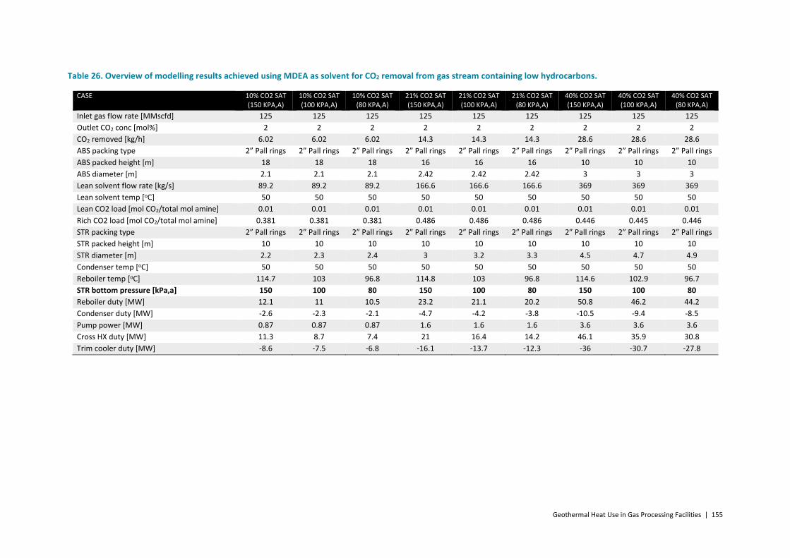
Geothermal Heat Use in Gas Processing Facilities | 155
Table 26. Overview of modelling results achieved using MDEA as solvent for CO2 removal from gas stream containing low hydrocarbons.
CASE 10% CO2 SAT (150 KPA,A)
10% CO2 SAT (100 KPA,A)
10% CO2 SAT (80 KPA,A)
21% CO2 SAT (150 KPA,A)
21% CO2 SAT (100 KPA,A)
21% CO2 SAT (80 KPA,A)
40% CO2 SAT (150 KPA,A)
40% CO2 SAT (100 KPA,A)
40% CO2 SAT (80 KPA,A)
Inlet gas flow rate [MMscfd] 125 125 125 125 125 125 125 125 125 Outlet CO2 conc [mol%] 2 2 2 2 2 2 2 2 2 CO2 removed [kg/h] 6.02 6.02 6.02 14.3 14.3 14.3 28.6 28.6 28.6 ABS packing type 2” Pall rings 2” Pall rings 2” Pall rings 2” Pall rings 2” Pall rings 2” Pall rings 2” Pall rings 2” Pall rings 2” Pall rings ABS packed height [m] 18 18 18 16 16 16 10 10 10 ABS diameter [m] 2.1 2.1 2.1 2.42 2.42 2.42 3 3 3 Lean solvent flow rate [kg/s] 89.2 89.2 89.2 166.6 166.6 166.6 369 369 369 Lean solvent temp [oC] 50 50 50 50 50 50 50 50 50 Lean CO2 load [mol CO2/total mol amine] 0.01 0.01 0.01 0.01 0.01 0.01 0.01 0.01 0.01 Rich CO2 load [mol CO2/total mol amine] 0.381 0.381 0.381 0.486 0.486 0.486 0.446 0.445 0.446 STR packing type 2” Pall rings 2” Pall rings 2” Pall rings 2” Pall rings 2” Pall rings 2” Pall rings 2” Pall rings 2” Pall rings 2” Pall rings STR packed height [m] 10 10 10 10 10 10 10 10 10 STR diameter [m] 2.2 2.3 2.4 3 3.2 3.3 4.5 4.7 4.9 Condenser temp [oC] 50 50 50 50 50 50 50 50 50 Reboiler temp [oC] 114.7 103 96.8 114.8 103 96.8 114.6 102.9 96.7 STR bottom pressure [kPa,a] 150 100 80 150 100 80 150 100 80 Reboiler duty [MW] 12.1 11 10.5 23.2 21.1 20.2 50.8 46.2 44.2 Condenser duty [MW] -2.6 -2.3 -2.1 -4.7 -4.2 -3.8 -10.5 -9.4 -8.5 Pump power [MW] 0.87 0.87 0.87 1.6 1.6 1.6 3.6 3.6 3.6 Cross HX duty [MW] 11.3 8.7 7.4 21 16.4 14.2 46.1 35.9 30.8 Trim cooler duty [MW] -8.6 -7.5 -6.8 -16.1 -13.7 -12.3 -36 -30.7 -27.8

156 | Geothermal Heat Use in Gas Processing Facilities
Table 27. Overview of modelling results achieved using MDEA as solvent for 10% and 21% CO2 removal with random packing, and gas stream containing higher hydrocarbon content.
CASE 10% CO2 SAT (150 KPA,A)
10% CO2 SAT (100 KPA,A)
10% CO2 SAT (80 KPA,A)
21% CO2 SAT (150 KPA,A)
21% CO2 SAT (100 KPA,A)
21% CO2 SAT (80 KPA,A)
Inlet gas flow rate [MMscfd] 125 125 125 125 125 125 Outlet CO2 conc [mol%] 2 2 2 2 2 2 CO2 removed [kg/h] 6.02 6.02 6.02 14.3 14.3 14.3 ABS packing type 2” Pall rings 2” Pall rings 2” Pall rings 2” Pall rings 2” Pall rings 2” Pall rings ABS packed height [m] 18 18 18 16 16 16 ABS diameter [m] 2.15 2.15 2.15 2.46 2.46 2.46 Lean solvent flow rate [kg/s] 89.5 89.5 89.5 167.3 167.3 167.3 Lean solvent temp [oC] 50 50 50 50 50 50 Lean CO2 load [mol CO2/total mol amine] 0.01 0.01 0.01 0.01 0.01 0.01 Rich CO2 load [mol CO2/total mol amine] 0.38 0.38 0.38 0.484 0.484 0.484 STR packing type 2” Pall rings 2” Pall rings 2” Pall rings 2” Pall rings 2” Pall rings 2” Pall rings STR packed height [m] 10 10 10 10 10 10 STR diameter [m] 2.2 2.32 2.39 3.0 3.2 3.3 Condenser temp [oC] 50 50 50 50 50 50 Reboiler temp [oC] 114.7 102.9 96.8 114.7 102.9 96.7 STR bottom pressure [kPa,a] 150 100 80 150 100 80 Reboiler duty [MW] 12.1 11.1 10.6 23.3 21.2 20.3 Condenser duty [MW] -2.6 -2.3 -2.1 -4.7 -4.3 -3.8 Pump power [MW] 0.9 0.9 0.9 1.6 1.6 1.6 Cross HX duty [MW] 11.4 8.8 7.5 21.1 16.6 14.3 Trim cooler duty [MW] -8.6 -7.4 -6.8 -16.1 -13.7 -12.3

Geothermal Heat Use in Gas Processing Facilities | 157
Table 28. Overview of modelling results achieved using MDEA as solvent for 40% CO2 removal with random packing from gas stream containing higher hydrocarbon content. Cooler temperatures of 40 and 50°C.
CASE 40% CO2 SAT (150 KPA,A)
40% CO2 SAT (100 KPA,A)
40% CO2 SAT (80 KPA,A)
40% CO2 SAT (150 KPA,A)
40% CO2 SAT (100 KPA,A)
40% CO2 SAT (80 KPA,A)
Inlet gas flow rate [MMscfd] 125 125 125 125 125 125 Outlet CO2 conc [mol%] 2 2 2 2 2 2 CO2 removed [kg/h] 28.6 28.6 28.6 28.6 28.6 28.6 ABS packing type 2” Pall rings 2” Pall rings 2” Pall rings 2” Pall rings 2” Pall rings 2” Pall rings ABS packed height [m] 12 12 12 11 11 11 ABS diameter [m] 3.03 3.03 3.03 2.94 2.94 2.94 Lean solvent flow rate [kg/s] 364 364 364 330.5 330.5 330.5 Lean solvent temp [oC] 40 40 40 50 50 50 Lean CO2 load [mol CO2/total mol amine] 0.01 0.01 0.01 0.01 0.01 0.01 Rich CO2 load [mol CO2/total mol amine] 0.45 0.45 0.449 0.496 0.496 0.496 STR packing type 2” Pall rings 2” Pall rings 2” Pall rings 2” Pall rings 2” Pall rings 2” Pall rings STR packed height [m] 10 10 10 10 10 10 STR diameter [m] 4.7 4.9 5 4.3 4.5 4.6 Condenser temp [oC] 40 40 40 50 50 50 Reboiler temp [oC] 114.8 102.9 96.8 114.7 102.9 96.8 STR bottom pressure [kPa,a] 150 100 80 150 100 80 Reboiler duty [MW] 55.5 50.8 48.7 46.1 42 40.2 Condenser duty [MW] -11.4 -10.5 -9.9 -9.4 -8.4 -7.6 Pump power [MW] 3.5 3.5 3.5 3.2 3.2 3.2 Cross HX duty [MW] 51.2 40.9 35.9 41.7 32.7 28.2 Trim cooler duty [MW] -42 -36.9 -34.1 -31.9 -27 -24.3

158 | Geothermal Heat Use in Gas Processing Facilities
Activated Methyldiethanolamine (PZMDEA) Whilst MDEA is a low energy solvent, it can also have slow kinetics. It is sometimes ‘activated’ by adding a few wt% of faster reacting primary or secondary amines. Piperazine (PZ) is a fast reacting secondary amine commonly added to MDEA.
The concentration of the activated solvent used in the simulations was 45 wt% MDEA with 5 wt% PZ. As MDEA is the amine in highest concentration, maximum allowable CO2 loadings have been kept the same as used for the 50 wt% MDEA solvent (i.e. max lean loading 0.01 mol CO2/mol (MDEA+PZ), max rich loading 0.5 mol CO2/mol (MDEA+PZ)). An overview of the results achieved with the PZMDEA blend is provided in Table 29. A minimum in regeneration energy was noted to occur between stripping column pressures of 1 – 1.5 bar,a. As such results achieved with a stripping column pressure of 1.3 bar,a are also included.
Table 29. Overview of modelling results achieved using PZMDEA as solvent for CO2 removal from gas stream containing higher hydrocarbon content.
The results indicate that the PZ activated MDEA blend is easily able to reach the outlet CO2 concentration requirement. In order to keep below the maximum rich loading limit, solvent flow rate was increased, leading to nearly 100% capture of the CO2 and an increase in regeneration energy requirement. This highlights that this solvent is over-specified for this case. An option for making this solvent more suited to this case would be to use a lower efficiency packing. Additionally, lower solvent concentrations could be used. However, as this solvent is very reactive to CO2 under the conditions considered here, it will still readily absorb the CO2. As such, high solvent flow rates will still likely be required when using lower solvent concentrations in order to maintain the solvent below the maximum rich loading limit.
CASE 21% CO2 SAT (200 KPA,A)
21% CO2 SAT (150 KPA,A)
21% CO2 SAT (130 KPA,A)
21% CO2 SAT (100 KPA,A)
21% CO2 SAT (80 KPA,A)
Inlet gas flow rate [MMscfd] 125 125 125 125 125 Outlet CO2 conc [mol%] 0.02 0.02 0.02 0.02 0.02 CO2 removed [kg/s] 15.5 15.5 15.5 15.5 15.5 ABS packing type 2” Pall rings 2” Pall rings 2” Pall rings 2” Pall rings 2” Pall rings ABS packed height [m] 10 10 10 10 10 ABS diameter [m] 2.46 2.46 2.46 2.46 2.46 Lean solvent flow rate [kg/s] 170 170 170 170 170 Lean solvent temp [oC] 50 50 50 50 50 Lean CO2 load [mol CO2/total mol amine]
0.01 0.01 0.01 0.01 0.01
Rich CO2 load [mol CO2/total mol amine]
0.489 0.489 0.488 0.489 0.489
STR packing type 2” Pall rings 2” Pall rings 2” Pall rings 2” Pall rings 2” Pall rings STR packed height [m] 16 16 16 16 16 STR diameter [m] 3.43 3.54 3.59 3.99 4.51 Condenser temp [oC] 50 50 50 50 50 Reboiler temp [oC] 125.3 116.2 111.9 104.2 98 STR bottom pressure [kPa,a] 200 150 130 100 80 Reboiler duty [MW] 32.2 31 30.5 37 47 Condenser duty [MW] -7.5 -7.3 -7.3 -14.3 -24.4 Pump power [MW] 1.7 1.7 1.7 1.7 1.7 Cross HX duty [MW] 22.2 18.3 16.5 13.5 11.2 Trim cooler duty [MW] -22.6 -20.8 -19.9 -18.1 -16.6

Geothermal Heat Use in Gas Processing Facilities | 159
Diethanolamine (DEA) Diethanolamine has been widely used in the past, but is less frequently used today. As with the PZMDEA blend, it is also a fast reacting solvent for the conditions simulated here. Results achieved using DEA to treat the saturated gas stream containing 21% CO2 are provided in Table 30.
Table 30. Overview of modelling results achieved using DEA as solvent for CO2 removal from gas stream containing higher hydrocarbon content.
As with the PZ/MDEA results, the 30 wt% DEA solvent was again easily able to meet the treating requirement. Increasing the solvent flow rate to avoid the maximum rich loading limit leadS to high solvent flow rates and hence high pump and reboiler duty requirements. As with the PZ/MDEA case, using a lower efficiency packing and lowering the solvent concentration are possible methods for improving the performance of this solvent for this application. However, as noted above, DEA is not generally suited to treating high CO2 content gas streams due to the potential for it to undergo irreversible reactions with CO2. As such, DEA is not considered a suitable solvent for this application.
CASE 21% CO2 SAT (200 KPA,A)
21% CO2 SAT (150 KPA,A)
21% CO2 SAT (100 KPA,A)
21% CO2 SAT (80 KPA,A)
Inlet gas flow rate [MMscfd] 125 125 125 125 Outlet CO2 conc [mol%] 0.01 0.01 0.01 0.01 CO2 removed [kg/s] 15.5 15.5 15.5 15.5 ABS packing type 2” Pall rings 2” Pall rings 2” Pall rings 2” Pall rings ABS packed height [m] 10 10 10 10 ABS diameter [m] 2.73 2.73 2.73 2.73 Lean solvent flow rate [kg/s] 300 300 300 300 Lean solvent temp [oC] 50 50 50 50 Lean CO2 load [mol CO2/total mol amine] 0.07 0.07 0.07 0.07 Rich CO2 load [mol CO2/total mol amine] 0.483 0.483 0.483 0.483 STR packing type 2” Pall rings 2” Pall rings 2” Pall rings 2” Pall rings STR packed height [m] 16 16 16 16 STR diameter [m] 4.14 4.4 4.75 4.93 Condenser temp [oC] 50 50 50 50 Reboiler temp [oC] 121.1 112.4 100.9 94.9 STR bottom pressure [kPa,a] 200 150 100 80 Reboiler duty [MW] 51.4 51.65 52.3 52.5 Condenser duty [MW] -14 -14.3 -14.4 -14.7 Pump power [MW] 2.9 2.9 2.9 2.9 Cross HX duty [MW] 46.4 36.4 23.7 17.6 Trim cooler duty [MW] -36.4 -36.1 -35.1 -34

160 | Geothermal Heat Use in Gas Processing Facilities
Monoethanolamine (MEA) An overview of the results achieved when operating with 30 wt% MEA are provided in Table 31. The results show that the fast reacting MEA solvent is also over-specified for the conditions considered here. It readily absorbs the CO2 from the gas stream, achieving exit CO2 concentrations below the target 2 vol%. Higher solvent flow rates were required to maintain the rich CO2 solvent load below the maximum limit. Again, using a lower efficiency packing and lowering solvent concentration may aid operation with this solvent under the conditions considered here.
The results provided in Table 31 highlight that stripping CO2 out of MEA solutions is aided by raising the regeneration temperature. This is due to the characteristics of the aqueous MEA solution. The vapour pressure of CO2 over the amine solution increases with temperature more rapidly than the vapour pressure of the water/amine mixture over the same solution. It should be noted that this phenomenon is particular to CO2 in MEA and will not necessarily occur with other amines [40]. As a result, MEA based CO2 removal plants benefit from operation at high stripping column temperatures/pressures. To achieve maximum use from geothermal heat sources however operation at lower stripping column temperatures/pressures is beneficial. This makes the aqueous MEA solvent less attractive for pairing with geothermal heat. As such, operation with MEA was not considered further in this study.
Table 31. Overview of modelling results using 30 wt% MEA to treat gas stream containing 21 % CO2 and higher hydrocarbon content.
CASE 21% CO2 SAT 200
21% CO2 SAT 150
21% CO2 SAT 100
21% CO2 SAT 80
Inlet gas flow rate [MMscfd] 125 125 125 125
Outlet CO2 conc [mol%] 0 0 0 0
CO2 removed [kg/s] 15.5 15.5 15.5 15.5
ABS packing type 2” Pall rings 2” Pall rings 2” Pall rings 2” Pall rings
ABS packed height [m] 10 10 10 10
ABS diameter [m] 2.51 2.51 2.51 2.51
Lean solvent flow rate [kg/s] 215 215 215 215
Lean solvent temp [oC] 50 50 50 50
Lean CO2 load [mol CO2/total mol amine] 0.15 0.15 0.15 0.15
Rich CO2 load [mol CO2/total mol amine] 0.484 0.484 0.484 0.484
STR packing type 2” Pall rings 2” Pall rings 2” Pall rings 2” Pall rings
STR packed height [m] 16 16 16 16
STR diameter [m] 4.2 4.78 6.1 7.09
Condenser temp [oC] 50 50 50 50
Reboiler temp [oC] 123.3 114.5 102.8 96.6
STR bottom pressure [kPa,a] 200 150 100 80
Reboiler duty [MW] 55.9 69.5 111 147
Condenser duty [MW] -17.9 -31.5 -73 -109.1
Pump power [MW] 2.1 2.1 2.1 2.1
Cross HX duty [MW] 23.4 16.4 8.1 4.5
Trim cooler duty [MW] -36.6 -36.1 -34.5 -32.9

Geothermal Heat Use in Gas Processing Facilities | 161
Conclusions Ultimately, the inlet gas conditions and composition will determine the most appropriate acid gas removal technology. This can be seen in the results here to some extent. Where CO2 concentrations (partial pressure) are high, lower energy slower reacting solvents such as MDEA are appropriate. Fast reacting solvents (such as MEA, PZMDEA, DEA) are over-specified for this conditions considered here, achieving CO2 exit concentrations below the target (< 2 vol%). It may be possible to tailor conditions to more suit these fast reacting solvents, such as using lower efficiency packing. However, external review [77] has indicated that MEA and DEA are not commonly used commercially. In addition, the characteristics of the MEA and DEA solvents favour operation at high stripping column temperatures and pressures, making them less suitable for integrating with a geothermal heat source for the conditions considered here. Where the gas stream to be treated is available at lower pressures, the faster reacting PZMDEA blended solvent should be considered. However, for the high pressure application considered in this report, the PZMDEA blend is also over-specified.
Altering the amine solvent had a small effect on the regeneration temperature required. Changing the stripping column pressure was found to have a much more notable effect. Lowering the stripping column pressure lowered the temperature. For MEA and DEA, operation at lower pressures required higher regeneration energy requirements. PZMDEA achieved a minimum regeneration energy requirement at a stripping column pressure of 1.3 bar,a for the conditions evaluated here. For MDEA, lowering the stripping column pressure lowered the regeneration energy requirement.
For the cases investigated here, the MDEA solvent was able to consistently achieve the required CO2 removal with minimum energy requirement. As a result a number of additional scenarios were completed with this solvent. The results of the MDEA cases were also used in the subsequent dehydration simulations, and for economic analysis.
Future work The process operating conditions chosen were often limited by the maximum allowable solvent CO2 loading (based on acceptable corrosion limits). For geothermal heat integration, it may be attractive to operate the regeneration column at lower temperatures than typically used in gas processing applications, as this allows maximum utilisation of the geothermal heat. If amine regeneration is performed at lower temperatures, it is possible that corrosion rates will be reduced. This could potentially allow a wider range of acceptable solvent CO2 loadings, leading to lower allowable solvent flow rates, which will in turn lower operating costs. However, before the limits on CO2 loading in solvents can safely be altered, work will need to be completed to assess corrosion rates under the modified operating conditions. Lower stripping column temperatures will also likely lead to lower solvent degradation rates. This will lower the amine make-up rate required, leading to operating cost reductions. The amount of this benefit is not known, and would require degradation tests to be completed at the lower stripping column temperatures.
For the evaluation completed here a standard absorption/desorption process was simulated. Different regeneration pressures were modelled to evaluate the effect on regeneration

162 | Geothermal Heat Use in Gas Processing Facilities
temperature and energy requirements. It should be noted that this is not necessarily the most optimal plant configuration, with the potential for further reductions in energy requirement through process modifications. Further analysis is required to determine whether any of the common heat integration processes used to date are applicable to the case incorporating a geothermal heat source.

Geothermal Heat Use in Gas Processing Facilities | 163
Appendix D Modelling of Natural Gas Dehydration using Glycol
For this project dehydration to 100 mg/Sm3 was considered. As such a liquid desiccant system using glycol was simulated to determine whether the heat requirement for this process lends itself to incorporation of geothermal heat.
There are a number of different glycols available for dehydration, with TEG the most commonly used. TEG regeneration is typically performed at atmospheric pressure and 200°C as thermal decomposition of TEG is an issue at higher temperatures. TEG is recommended for use with contactor temperatures above 50°C to minimise vapour losses [40].
DEG is favoured when contactor temperatures are below 10°C due to the high viscosity of TEG in this temperature range. DEG has a high vapour pressure which can lead to high losses in the contactor. DEG has a lower decomposition temperature, so regeneration tends to take place at around 160°C. This lower regeneration temperature means that DEG desiccants often can’t get pure enough for most dehydration applications [80].
When dehydrating to very low dew points, such as those required upstream of a refrigeration process, the TEG concentration must be sufficient to dry the gas to the hydrate dew point [41]. Concentration of TEG to 98.5 to 99% can be achieved in a simple atmospheric pressure still. For the cases considered here, 99 wt% TEG has been used. It should be noted that for more stringent dehydration requirements, enhanced regeneration processes would be required, such as using stripping steam in the regenerator. Enhanced stripping can also be achieved by operating the reconcentrator (stripping column) under vacuum conditions.
Calculation method To size the dehydration plant and calculate the energy requirement, the worked examples provided in the GPSA data book were followed (Examples 20-11 and 20-12). Optimised gas treating also provided a template of the GPSA worked example in ProTreat®. This template was modified for the conditions of interest in this study, with results providing information on stream composition and regeneration temperature. A flow diagram of the revised ProTreat® model is provided in Figure 68.

164 | Geothermal Heat Use in Gas Processing Facilities
Figure 68. ProTreat® model of glycol dehydration plant.
The sweet natural gas stream leaving the absorber column in the CO2 removal plant provided the inlet gas stream for the dehydration plant. For the calculations completed here, the exiting gas stream from the cases using MDEA as the solvent were used. ProTreat® was used to provide an estimate of the water content of this gas stream in mg/Sm3 (Win). The target outlet water concentration of the dry gas for the examples here was 100 mg/Sm3 (Wout). The fraction of water removal required is then determined by equation 1.
𝑊𝑊𝑖𝑖𝑖𝑖−𝑊𝑊𝑜𝑜𝑜𝑜𝑜𝑜𝑊𝑊𝑖𝑖𝑖𝑖
(1)
The inlet water mass flow rate to the dehydration column is known, and equation 1 can then be used to calculate the water removal required in the dehydration plant.
99 wt% TEG was used as the dehydration solvent. 2.5 theoretical stages were required for the desired fractional water removal. A tray efficiency of 25% was used, leading to 10 bubble cap trays being required in the absorber column. Bubble cap trays are often used in glycol contactors due to the low L/G ratios. The absorber and stripping column diameters were determined from the ProTreat® simulation.
Most economic dehydration plant designs employ circulation rates of about 15 – 40 L TEG/kg H2O [41]. In the GPSA worked example, a TEG circulation rate of 25 L TEG/kg H2O was specified, and the same flow rate was used here.
Sizing the stripper requires determining the reboiler duty required to regenerate the rich glycol. This was estimated following the GPSA data book worked example (20-12). This was completed for 25 L TEG/kg H2O entering the reboiler at 150°C, with the reboiler operating at slightly above atmospheric pressure (105 kPaa). The energy requirement is the sum of the sensible heat (Qsens) required to heat the glycol up to the regeneration temperature (200°C), the energy required to evaporate the water from the glycol (Qvap), and the condenser duty (Qcond). In addition, a 10% allowance for heat loss is also incorporated. Some reflux of water

Geothermal Heat Use in Gas Processing Facilities | 165
to the top of the stripper is required to wash the exiting gas stream and minimise glycol losses. Reflux is held at a minimum because it directly affects heat required in the reboiler. Typically around 25% of the evaporated water will provide sufficient reflux to lower glycol losses. The reboiler duty for the stripper can then be calculated via equations 2 – 5.
𝑄𝑄𝑠𝑠𝑠𝑠𝑠𝑠𝑠𝑠 = 𝑚𝑚𝐶𝐶𝑝𝑝∆𝑑𝑑 (2)
Where m is the mass flow rate of the TEG (kg/s), Cp is the specific heat (roughly 2.784 kJ/kg.oC), and ∆T is the temperature increase required (from 150 to 200°C).
𝑄𝑄𝑣𝑣𝑣𝑣𝑝𝑝 = 𝑚𝑚𝑤𝑤∆𝐻𝐻𝑣𝑣𝑣𝑣𝑝𝑝 (3)
Where mw is the mass flow rate of water removed (kg/s) and ∆Hvap is the enthalpy of vaporisation of water (roughly 2260 kJ/kgH2O).
𝑄𝑄𝑐𝑐𝑐𝑐𝑠𝑠𝑐𝑐 = 0.25𝑄𝑄𝑣𝑣𝑣𝑣𝑝𝑝 (4)
The total energy requirement, including 10% heat loss, is then given by equation 5.
𝑄𝑄𝑟𝑟𝑠𝑠𝑟𝑟𝑐𝑐𝑟𝑟𝑟𝑟𝑠𝑠𝑟𝑟 = 1.1(𝑄𝑄𝑠𝑠𝑠𝑠𝑠𝑠𝑠𝑠 + 𝑄𝑄𝑣𝑣𝑣𝑣𝑝𝑝 + 𝑄𝑄𝑐𝑐𝑐𝑐𝑠𝑠𝑐𝑐) (5)
The ProTreat® template was used to size the stripper, including approximately 6 m of 2 inch Pall ring packing. The ProTreat® template of the dehydration plant was also run under vacuum conditions to determine the effect of regeneration pressure on the temperature in the stripping column.
RESULTS
Triethylene glycol (TEG) An overview of the results achieved for the TEG dehydration system is provided in Table 32. It should be noted that the water removal requirement for the system simulated here was quite low, leading to low energy requirements for the dehydration. Results achieved when operating the stripper at lower pressures are provided in Table 33.
The results show that regeneration of TEG typically requires temperatures around 200°C, which is likely above the temperature availability of most geothermal heat streams. Operating the stripping column at reduced pressure did lower the stripper temperature, though temperatures are still high.

166 | Geothermal Heat Use in Gas Processing Facilities
Table 32. Overview of TEG dehydration system results.
MDEA BASE CASE EXIT CONDITIONS MDEA, HIGH HYDROCARBON, EXIT CONDITIONS CASE 10% CO2 SAT 21% CO2 SAT 40% CO2 SAT 10% CO2 SAT 21% CO2 SAT 40% CO2 SAT Gas flow rate [MMscfd] 110.9 97.1 73.3 110.8 97.1 73.4 Gas flow rate [kg/h] 93550 81954 61841 114835 100529 75994 Temperature [oC] 50.8 50.6 50.4 50.9 50.6 50.5 Pressure [kPa,a] 7505 7506 7507 7505 7506 7507 Inlet water concentration [mg/Sm3] 1600 1444 1444 1560 1521 1511 Inlet water flow rate [kg/h] 208.9 165.5 124.9 208.8 174 135 Desired outlet water concentration [mg/Sm3]
100 100 100 100 100 100
Water removal efficiency required [frac]
0.938 0.931 0.931 0.936 0.934 0.934
TEG concentration [wt%] 99 99 99 99 99 99 TEG circulation rate [L TEG/kgH2O] 25 25 25 25 25 25 TEG flow rate [kg/h] 5453 4291 3237 5443 4532 3513 Number of trays required in absorber 10 10 10 10 10 10 Absorber diameter [m] 1.5 1.4 1.2 1.6 1.5 1.3 TEG temperature into stripper [oC] 150 150 150 150 150 150 Stripper temperature [oC] 200 200 200 200 200 200 Stripper column diameter [m] 0.3 0.2 0.2 0.3 0.3 0.2 Qsens [kW] 210.8 165.9 125.2 210.4 175.3 135.8 Qvap [kW] 122.9 96.7 73 122.7 102.2 79.2 Qcond [kW] 30.7 24.2 18.2 30.7 25.5 19.8 Total reboiler duty (including 10% heat loss) [kW]
400.9 315.5 238 400.2 333.3 258.3
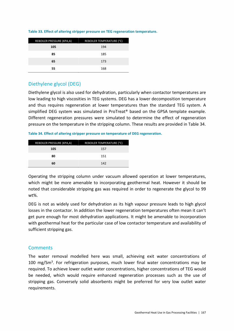
Geothermal Heat Use in Gas Processing Facilities | 167
Table 33. Effect of altering stripper pressure on TEG regeneration temperature.
Diethylene glycol (DEG) Diethylene glycol is also used for dehydration, particularly when contactor temperatures are low leading to high viscosities in TEG systems. DEG has a lower decomposition temperature and thus requires regeneration at lower temperatures than the standard TEG system. A simplified DEG system was simulated in ProTreat® based on the GPSA template example. Different regeneration pressures were simulated to determine the effect of regeneration pressure on the temperature in the stripping column. These results are provided in Table 34.
Table 34. Effect of altering stripper pressure on temperature of DEG regeneration.
Operating the stripping column under vacuum allowed operation at lower temperatures, which might be more amenable to incorporating geothermal heat. However it should be noted that considerable stripping gas was required in order to regenerate the glycol to 99 wt%.
DEG is not as widely used for dehydration as its high vapour pressure leads to high glycol losses in the contactor. In addition the lower regeneration temperatures often mean it can’t get pure enough for most dehydration applications. It might be amenable to incorporation with geothermal heat for the particular case of low contactor temperature and availability of sufficient stripping gas.
Comments The water removal modelled here was small, achieving exit water concentrations of 100 mg/Sm3. For refrigeration purposes, much lower final water concentrations may be required. To achieve lower outlet water concentrations, higher concentrations of TEG would be needed, which would require enhanced regeneration processes such as the use of stripping gas. Conversely solid absorbents might be preferred for very low outlet water requirements.
REBOILER PRESSURE (KPA,A) REBOILER TEMPERATURE (°C)
105 194
85 185
65 173
55 168
REBOILER PRESSURE (KPA,A) REBOILER TEMPERATURE (°C)
105 157
80 151
60 142
168 | Geothermal Heat Use in Gas Processing Facilities
The results here highlight that the dehydration plant utilises a lower amount of energy than the CO2 removal plant. When using TEG, the regeneration temperature is typically around 200°C, which may be too high for incorporating most geothermal heat sources. Operating the regeneration under vacuum does reduce the temperature, though not significantly (55 kPa,a requires regeneration at around 170°C). Using DEG provides regeneration at temperatures around 160°C. However this process suffers from high vapour losses and requires the availability of stripping gas for regeneration.
Due to the comparatively low energy requirement of the dehydration process, it is unlikely that it alone would provide a sufficient case for the use of geothermal heat. However, if geothermal heat was already available, and of sufficient temperature, there might be some benefit from using the heat in this process. Using vacuum regeneration is one possibility for lowering the temperature requirement in the stripping column. Vacuum regeneration (whilst maintaining column temperature) is sometimes used when higher glycol concentrations are required [40]. However, vacuum reboilers are not commonly used due to the added complexity. Air leaks into the system are not only a safety hazard, but the oxygen will also degrade the glycol. In addition, it is normally less expensive to use stripping gas [80].

Geothermal Heat Use in Gas Processing Facilities | 169
Appendix E Amine Gas Sweetening Equipment Design Assumptions
Reboiler
• Type – Kettle Reboiler • Approach temperature of 10°C • Base case utilises low pressure steam to heat the reboiler, entering as saturated steam
at 3.6 bar,a (140°C) and exiting as saturated liquid at 3.4 bar,a (138°C) • Base case heat transfer coefficient of 620 W/m2.K. Values 570-680 Wm2.K suggested
by literature [81] • Maximum tube side temperature of 150°C to prevent amine degradation [40]. Case of
175°C used as comparison. • Geothermal brine available at 175°C (9.5 bar,a), 150°C (5 bar,a) and 120°C (2.5 bar,a) • Pressure drop across reboiler of 50 kPa for geothermal brine • Overall heat transfer coefficient of 500 W/m2.K • 5% heat loss • Maximum reboiler surface area of 1,000 m2 [69] • Materials of construction - Carbon steel
Absorber and Stripper Columns
• Type – Packed Column • Materials of construction – Carbon steel throughout, except 316 Stainless Steel for top
of stripper and column internals • 2” metal Pall rings, random packing • Column height based on packed height, with 25% additional height for necessary
space at the bottom and top of the column, as well as 0.75 m for every 10 m of packed height for liquid collection, liquid distribution and supporting grid [82].
Trim Cooler
• Water used to cool the lean amine solution. • Water inlet temperature of 25°C and outlet of 45°C. • Water pressure of 3 bar,a • Heat transfer coefficient of 500 W/m2.K. Values 455-510 Wm2.K suggested by
literature [81] • 5% heat loss • Materials of construction - 316 Stainless Steel on lean solvent side

170 | Geothermal Heat Use in Gas Processing Facilities
Rich/Lean Heat Exchanger
• Heat transfer coefficient of 500 W/m2.K. Values 425-510 Wm2.K suggested by literature [81]
• 5% heat loss • Materials of construction - 316 Stainless Steel on lean solvent side
Condensor
• Approach temperature of 10°C • Water utilised • Water inlet temperature of 25°C and outlet of 40°C • Water pressure of 3 bar,a • Heat transfer coefficient of 450 W/m2.K. Values 400-510 Wm2.K suggested by
literature [81] • 5% heat loss • Materials of construction - 316 Stainless Steel
Recycle pump
• Type - Centrifugal • 75% pump efficiency • 95% drive efficiency

Geothermal Heat Use in Gas Processing Facilities | 171
Appendix F Gycol Gas Dehydration Equipment Design Assumptions
Reboiler
• Type – Kettle Reboiler • Approach temperature of 10°C • Base case utilises high pressure steam to heat the reboiler, entering as saturated
steam at 250°C (39.8 bar,a) and exiting as saturated liquid at 249°C (39.0 bar,a) • Base case heat flux of 18,930 W/m2 [43] • Geothermal brine available at 220°C (24 bar,a) and 240°C (34 bar,a) • Pressure drop across reboiler of 50 kPa for geothermal brine • Heat flux of 18,930 W/m2. Range of 6,000 – 8,000 Btu/hr.ft2 suggested by literature,
but 6,000 suggested to ensure against glycol decomposition [43]. • 5% heat loss • Maximum reboiler surface area of 1,000 m2 [69] • Materials of construction - Carbon steel
Absorber Column
• Type – Tray column • Tray spacing – 2 ft (60.96 cm) • Materials of construction - Carbon steel, with 316 stainless steel internals
Stripper Column
• Type – Packed Column • Materials of construction - Carbon steel, with 316 stainless steel internals • 2” metal Pall rings, random packing • Column height based on packed height, with 25% additional height for necessary
space at the bottom and top of the column, as well as 0.75 m for every 10 m of packed height for liquid collection, liquid distribution and supporting grid [82].
Feed/Bottoms Cross Flow Heat Exchanger
• Heat transfer coefficient of 60 W/m2.K [43] • 5% heat loss • Materials of construction - Carbon Steel
Cross Flow Heat Exchanger
• Heat transfer coefficient of 250 W/m2.K [43]

172 | Geothermal Heat Use in Gas Processing Facilities
• 5% heat loss • Materials of construction - Carbon Steel
Condensor
• Approach temperature of 10°C • Water utilised • Water inlet temperature of 25°C and outlet of 45°C • Water pressure of 3 bar,a • Heat transfer coefficient of 570 W/m2.K [80] • 5% heat loss • Materials of construction - Carbon Steel
Recycle pump
• Type - Centrifugal • 75% pump efficiency • 95% drive efficiency

Geothermal Heat Use in Gas Processing Facilities | 173
Appendix G Assumptions used for Alternative Means of Geothermal Heat Integration for the Amine Gas Sweetening Step – Using Working Fluid
Reboiler
• Type – Kettle Reboiler • Approach temperature of 10°C • Maximum tube side temperature of 150°C to prevent amine degradation [40] • Working fluid (water) inlet temperature of 150°C (5 bar,a) • Pressure drop across reboiler of 50 kPa for geothermal brine • Overall heat transfer coefficient of 500 W/m2.K • 5% heat loss • Maximum reboiler surface area of 1,000 m2 [69] • Materials of construction - Carbon steel
Brine/Working fluid heat exchanger
• Approach temperature of 10°C • Heat transfer coefficient of 380 W/m2.K • Geothermal brine available at 200°C (16 bar,a) • Pressure drop across heat exchanger of 50 kPa for both streams • 5% heat loss • Materials of construction - Carbon steel
Working fluid recycle pump
• Type – Centrifugal • Inlet pressure 4.5 bar,a • Outlet pressure 5.5 bar,a • 75% pump efficiency • 95% drive efficiency

174 | Geothermal Heat Use in Gas Processing Facilities
Appendix H Gas-Fired Steam Boiler Assumptions
High Pressure Steam Boiler
• Natural gas feed • Raising of high pressure steam at 250°C (39.76 bar,a) • Heat loss of 5%
Natural Gas Feed
• Energy value = 39.3 MJ/m3 [53] • CO2 released during natural gas combustion in the steam boiler = 51.2 kg CO2/GJ
natural gas [53] • Total CO2 equivalent (as a result of CO2, CH4 and N2O) during natural gas combustion
in the steam boiler = 62.6 kg CO2e/GJ natural gas [53]

Geothermal Heat Use in Gas Processing Facilities | 175
Appendix I Capital and Running Cost Assumptions Table 35. Characteristics of cases examined.
Case No. CO2 in input gas stream (%) Geothermal Temp (°C) Reboiler pressure (bar,a) 40-200-1.5a 40 200 1.5 40-200-1a 40 200 1
40-200-0.8a 40 200 0.8 40-200-1.5 40 200 1.5 40-200-1 40 200 1
40-200-0.8 40 200 0.8 40-175-1.5 40 175 1.5 40-175-1 40 175 1
40-175-0.8 40 175 0.8 40-150-1.5 40 150 1.5 40-150-1 40 150 1
40-150-0.8 40 150 0.8 40-120-1 40 120 1
40-120-0.8 40 120 0.8 40-gas* 40 NA 1.5
21-200-1.5a 21 200 1.5 21-200-1a 21 200 1
21-200-0.8a 21 200 0.8 21-200-1.5 21 200 1.5 21-200-1 21 200 1
21-200-0.8 21 200 0.8 21-175-1.5 21 175 1.5 21-175-1 21 175 1
21-175-0.8 21 175 0.8 21-150-1.5 21 150 1.5 21-150-1 21 150 1
21-150-0.8 21 150 0.8 21-120-1 21 120 1
21-120-0.8 21 120 0.8 21-gas* 21 NA 1.5
10-200-1.5a 10 200 1.5 10-200-1a 10 200 1
10-200-0.8a 10 200 0.8 10-200-1.5 10 200 1.5 10-200-1 10 200 1
10-200-0.8 10 200 0.8 10-175-1.5 10 175 1.5 10-175-1 10 175 1
10-175-0.8 10 175 1.5 10-150-1.5 10 150 1 10-150-1 10 150 0.8
10-150-0.8 10 150 1.5 10-120-1 10 120 1
10-120-0.8 10 120 0.8 10-gas* 10 NA 1.5
* Base cases where low pressure steam is used, instead of geothermal brine, to heat the reboiler. a Cases where geothermal brine at 200°C is passed through a heat exchanger and cooled before being used to heat the reboiler

176 | Geothermal Heat Use in Gas Processing Facilities
Table 36. Geothermal capital cost components and total geothermal capital cost including 18.5% contingency and project management, per project. The total cost also includes the costs of exploration, well head and brine reticulation systems and reservoir stimulation. The operating cost is also shown.
Case No. Total brine flow rate
(kg/s)
Production wells
Total wells Total well drilling
campaign
Cost of confirmation
wells ($million/ project)
Cost of first non-
confirmation well ($million
/ project)
Pump cost ($million /project)
Well cost ($/project)
Total geothermal
cost ($million /project)
Geothermal operating cost ($million/year)
40-200-1.5a 182.8 3 6 7 46 19 1.4 122.8 147.2 4.64 40-200-1a 141.0 2 4 5 46 19 0.9 103.0 123.2 3.40
40-200-0.8a 124.9 2 4 5 46 19 0.9 91.2 109.3 3.23 40-200-1.5 150.8 2 4 5 46 19 0.9 110.2 131.7 3.50 40-200-1 118.7 2 4 5 46 19 0.9 86.7 103.9 3.16
40-200-0.8 106.1 2 4 5 46 19 0.9 77.5 92.9 3.03 40-175-1.5 233.5 3 6 7 46 19 1.4 156.9 187.6 5.13 40-175-1 171.3 3 6 7 46 19 1.4 115.1 138.1 4.53
40-175-0.8 148.7 2 4 5 46 19 0.9 108.6 129.9 3.48 40-150-1.5 451.5 6 12 13 27 11 2.8 277.0 331.6 9.73 40-150-1 272.2 4 8 9 27 11 1.9 175.0 209.6 6.35
40-150-0.8 221.5 3 6 7 27 11 1.4 148.9 178.1 5.01 40-120-1 2166.3 22 44 45 17 7 10.4 409.3 497.4 27.07
40-120-0.8 862.0 9 18 19 17 7 4.3 169.0 205.3 11.10 21-200-1.5a 83.3 1 2 3 46 19 0.5 75.5 90.0 2.04 21-200-1a 64.3 1 2 3 46 19 0.5 58.2 69.6 1.79
21-200-0.8a 57.0 1 2 3 46 19 0.5 51.6 61.8 1.70 21-200-1.5 68.7 1 2 3 46 19 0.5 62.2 74.3 1.85 21-200-1 54.1 1 2 3 46 19 0.5 49.0 58.6 1.66
21-200-0.8 48.4 1 2 3 46 19 0.5 43.8 52.5 1.59 21-175-1.5 106.4 2 4 5 46 19 0.9 77.7 93.2 3.04 21-175-1 78.1 1 2 3 46 19 0.5 70.8 84.4 1.97
21-175-0.8 67.9 1 2 3 46 19 0.5 61.5 73.4 1.84 21-150-1.5 227.9 3 6 7 27 11 1.4 153.2 183.2 5.08 21-150-1 137.4 2 4 5 27 11 0.9 100.4 120.0 3.36
21-150-0.8 111.7 2 4 5 27 11 0.9 81.6 97.8 3.09 21-120-1 1093.2 11 22 23 17 7 5.2 212.0 257.4 13.64
21-120-0.8 434.5 5 10 11 17 7 2.4 89.4 108.8 6.10

Geothermal Heat Use in Gas Processing Facilities | 177
Case No. Total brine flow rate
(kg/s)
Production wells
Total wells Total well drilling
campaign
Cost of confirmation
wells ($million/ project)
Cost of first non-
confirmation well ($million
/ project)
Pump cost ($million /project)
Well cost ($/project)
Total geothermal
cost ($million /project)
Geothermal operating cost ($million/year)
10-200-1.5a 43.4 1 2 3 46 19 0.5 39.3 47.1 1.52 10-200-1a 33.6 1 2 3 46 19 0.5 30.4 36.6 1.40
10-200-0.8a 29.8 1 2 3 46 19 0.5 27.0 32.5 1.35 10-200-1.5 35.8 1 2 3 46 19 0.5 32.4 38.9 1.43 10-200-1 28.2 1 2 3 46 19 0.5 25.6 30.9 1.33
10-200-0.8 25.3 1 2 3 46 19 0.5 22.9 27.7 1.29 10-175-1.5 55.4 1 2 3 46 19 0.5 50.2 60.0 1.68 10-175-1 40.8 1 2 3 46 19 0.5 36.9 44.3 1.49
10-175-0.8 35.4 1 2 3 46 19 0.5 32.1 38.6 1.42 10-150-1.5 118.7 2 4 5 27 11 0.9 86.7 103.8 3.16 10-150-1 71.7 1 2 3 27 11 0.5 65.0 77.6 1.89
10-150-0.8 58.4 1 2 3 27 11 0.5 52.9 63.3 1.72 10-120-1 570.9 6 12 13 17 7 2.8 115.4 140.1 7.44
10-120-0.8 227.3 3 6 7 17 7 1.4 50.1 61.0 3.61


Geothermal Heat Use in Gas Processing Facilities | 1
Table 37. Details of the reboiler costing and the total gas sweetening plant capital costs
Case No. Number of reboilers needed
Individual reboiler surface area (m3)
Total reboiler equipment cost
($million)
Capital cost gas sweetening plant
($million) 40-200-1.5a 5 963 1.06 41.7 40-200-1a 4 945 0.84 36.4
40-200-0.8a 3 1122 0.72 40.6 40-200-1.5 3 942 0.64 37.1 40-200-1 3 795 0.57 36.8
40-200-0.8 3 731 0.53 37.7 40-175-1.5 4 879 0.80 38.1 40-175-1 3 966 0.65 33.3
40-175-0.8 3 878 0.60 38.1 40-150-1.5 5 963 1.06 39.6 40-150-1 4 945 0.84 34.4
40-150-0.8 3 1122 0.72 38.8 40-120-1 6 1108 1.43 37.9
40-120-0.8 5 1090 1.17 35.2 40-gas* 3 968 0.64 37.1
21-200-1.5a 3 738 0.52 22.5 21-200-1a 2 864 0.39 19.5
21-200-0.8a 2 770 0.36 22.4 21-200-1.5 2 646 0.33 16.8 21-200-1 1 1089 0.24 16.4
21-200-0.8 1 1003 0.23 19.5 21-175-1.5 2 805 0.37 19.1 21-175-1 2 662 0.32 16.8
21-175-0.8 2 603 0.30 20.0 21-150-1.5 3 738 0.52 20.0 21-150-1 2 864 0.39 17.2
21-150-0.8 2 770 0.36 20.3 21-120-1 3 1017 0.67 25.2
21-120-0.8 3 834 0.57 17.9 21-gas* 2 731 0.34 19.0
10-200-1.5a 2 575 0.29 13.5 10-200-1a 1 902 0.20 11.8
10-200-0.8a 1 805 0.18 13.8 10-200-1.5 1 672 0.17 11.2 10-200-1 1 569 0.15 10.1
10-200-0.8 1 524 0.14 12.3 10-175-1.5 1 838 0.19 11.4 10-175-1 1 691 0.17 10.2
10-175-0.8 1 630 0.16 12.4 10-150-1.5 2 575 0.29 12.0 10-150-1 1 902 0.20 10.4
10-150-0.8 1 805 0.18 12.5 10-120-1 2 797 0.37 11.4
10-120-0.8 2 654 0.32 14.6 10-gas* 1 761 0.18 13.7

2 | Geothermal Heat Use in Gas Processing Facilities
Table 38. Summary of costs assumed per case.
Case No. Total gas processing plant with geothermal ($million)
Total plant running costs ($million /year)
40-200-1.5a 160.6 16.8 40-200-1a 135.8 15.2
40-200-0.8a 127.6 15.9 40-200-1.5 143.5 15.3 40-200-1 119.8 15.1
40-200-0.8 111.3 15.5 40-175-1.5 191.6 16.8 40-175-1 145.7 15.9
40-175-0.8 142.8 15.9 40-150-1.5 314.4 20.6 40-150-1 207.0 17.5
40-150-0.8 184.2 17.2 40-120-1 452.8 36.0
40-120-0.8 204.1 22.4 40-gas* 33.3 12.5
21-200-1.5a 96.0 10.4 21-200-1a 76.2 9.9
21-200-0.8a 72.1 10.3 21-200-1.5 77.9 9.7 21-200-1 64.3 9.5
21-200-0.8 61.9 9.9 21-175-1.5 95.9 11.0 21-175-1 86.5 9.8
21-175-0.8 79.9 10.2 21-150-1.5 172.5 12.7 21-150-1 116.9 11.0
21-150-0.8 100.7 11.3 21-120-1 239.5 21.0
21-120-0.8 107.9 13.9 21-gas* 17.4 8.3
10-200-1.5a 52.3 8.2 10-200-1a 41.9 7.9
10-200-0.8a 40.2 8.2 10-200-1.5 43.4 7.9 10-200-1 35.7 7.7
10-200-0.8 34.8 8.0 10-175-1.5 61.4 8.1 10-175-1 47.1 7.8
10-175-0.8 44.1 8.1 10-150-1.5 98.8 9.5 10-150-1 75.3 8.2
10-150-0.8 65.1 8.4 10-120-1 128.9 13.3
10-120-0.8 64.9 10.4 10-gas* 12.8 6.9


4 | Geothermal Heat Use in Gas Processing Facilities
CONTACT US t 1300 363 400 +61 3 9545 2176 e [email protected] w www.csiro.au
AT CSIRO WE SHAPE THE FUTURE We do this by using science to solve real issues. Our research makes a difference to industry, people and the planet.
As Australia’s national science agency we’ve been pushing the edge of what’s possible for over 85 years. Today we have more than 5,000 talented people working out of 50-plus centres in Australia and internationally. Our people work closely with industry and communities to leave a lasting legacy. Collectively, our innovation and excellence places us in the top ten applied research agencies in the world.
WE ASK, WE SEEK AND WE SOLVE
FOR FURTHER INFORMATION Energy Flagship Cameron Huddlestone-Holmes t +61 7 3327 4672 e [email protected] w www.csiro.au/en/Research/EF Patrick Hartley t +61 3 9545 2595 e [email protected] w www.csiro.au/en/Research/EF