Geotechnical Testing Methods I - IIT Gandhinagarevents.iitgn.ac.in/2013/GAEE2013/handouts... · By...
26
1 Geotechnical Testing Methods I Ajanta Sachan Assistant Professor Civil Engineering IIT Gandhinagar Geotechnical Engg Structures… Buried right Under your Feet…!! Hiding World of Geotechnical Engg…!! Foundations Tunneling Shoring Soil Exploration
Transcript of Geotechnical Testing Methods I - IIT Gandhinagarevents.iitgn.ac.in/2013/GAEE2013/handouts... · By...

1
Geotechnical Testing Methods I
Ajanta SachanAssistant ProfessorCivil EngineeringIIT Gandhinagar
Geotechnical Engg Structures… Buried right Under your Feet…!!
Hiding World of Geotechnical Engg…!!
Foundations
Tunneling
Shoring
Soil Exploration

2
You pay for soil investigation whether you carry out or not. Infact you eventually pay more without a soil investigation.
Leaning Tower of Pisa
… Our Blunders become Monuments !

3
Unfortunately, soils are made by nature and not by man, and the products of nature are always complex…
As soon as we pass from steel and concrete to earth, the omnipotence of theory ceases to exist. Natural soil is never uniform…
Soil Investigation is unique for each soil site!
Terzaghi says:(Father of Soil Mechanics) Karl Terzaghi (1883-1963)
Typical Geotechnical Project
construction site
Geo-Laboratory~ for testing
Design Office~ for design & analysis
soil properties

4
Purpose of Geotechnical Testing?
ground
Can the soils Support the structure?
What is the impact of Excavation or Filling?
Are the earth and rock Slopes stable?
What type of Foundation is best suited for the structure?
How will the site respond to an Earthquake?
Is the site Contaminated?
Determine potential problems and Avoid surprises!!
S : Solid Soil particle
W: Liquid Water (electrolytes)
A: Air Air
v
s
Ve
VVoid ratio,
Three Phases in Soils

5
Grain Size Distribution
In Coarse grained soils …... By Sieve analysis (Dry/Wet)
Sieve Analysis Hydrometer Analysis
soil/water suspension
hydrometer
stack of sieves
sieve shaker
In Fine grained soils …... By Hydrometer analysis
Soil Groups
Fine grain soils
Coarse grain soils
0.002 200(300)
63(80)
2.36 (4.75; IS code)
0.075
Grain size (mm)
BoulderClay Silt Sand Gravel Cobble
Granular soils or Cohesion less soils
Cohesive soils

6
Rounded Subrounded
Subangular Angular
Sand and Gravelparticle size > 75 mm
Clay particle size < 2 mm
Soil particle shapes & sizes
Silt particle size = 75-2 mm
Typical Geotechnical Testing Plan
Borings: No. of bore holes, spacing
Ground Water Monitoring: measure the ground water level
Soil sampling: sampler (split spoon sampler, Shelby tube), Specimen (undisturbed, disturbed)
Laboratory Test: Index properties, Consolidation, Shear strength properties, Relative density, Permeability etc.
Field Test: In-situ dry density, Shear Strength, Plate Load Test

7
Borings: Number & Spacing
No hard and fast rule
Some guidelines – IS:1892-1979
For small projects
On plane site – 4 or 5 borings sufficient
On uneven site – add 1 or 2 more borings
For large projects: 50-100 m spacing in grid pattern
It is important to conduct borings as close as possible to column locations and strip footing locations.
Depth of Exploration

8
Other Exploration Techniques
Test Pits: Unlike boring, soil can be visually observed from the sides of the test pit. Pit is made by excavating ground (typical size =1.2mx1.2m) considering sufficient working space.
Trenches: Trenches are long shallow pits. They are more suitable for exploration on slopes than pits.
Suggestions:
Test pits suggested if required exploration depth = 2-4m
Trenches suggested for slopes (small)
Boring suggested for exploration depth > 4m
Indentifying the Weak Plane: Boring
Estimated Slip Surface

9
Boring Techniques
Auger Boring
Wash Boring
Rotary Boring
Percussion Boring
Use depends on
Nature of soil
Water table Depth
Sample Disturbance
Accuracy of soil exploration
Auger Boring for soils which can stay open without casing or drilling mud. It is not possible for sands below water table. Good for Highways, railways projects where small depth of soil exploration is needed.
18
Auger Boring
Push and rotate the auger until annular space of auger fills up
Withdraw the auger and clean it Repeat the process
Pro
ced
ure
1. Hand Auger – for shallow depth (3 - 5 m)
2. Power Driven Auger – for larger depth
3. Sand Bailer – Heavy duty pipe with cutting
edge– Lifted and then left to fall freely
under self weight. Additional weight (sinker) may be added for ease of sinking

10
19
4. Hollow Stem Auger
Auger Boring
20
Wash Boring
A casing pipe of 2-3 m length is driven into the soil by a heavy drop hammer.
The soil inside the casing is removed by means of a chopping bit attached to a drill rod which forces water at high pressure.
Soil mixed with water moves up in annular gap between drill rod and casing.
Samples are obtained at certain depth by removing drill rod and pushing a sampler instead.

11
Rotary Boring
Boring is done by rapidly rotating drilling bits attached to bottom of drilling rod.
Soil/rock cuttings removed by circulating drilling fluid
Samples are taken a certain depths by removing drill rod and placing sampler.
Mud Rotary Drilling: Hollow drilling rods are used to flow mud slurry (Bentonite) to check caving in of the material (soil) at bottom.
Core Drilling: Core barrels with diamond bit are used.
Design similar to wash boring
Useful when soil is resistant to auguring or wash boring
Percussion Boring
Dry boring or water circulated to remove loose soil
Heavy drilling bit or chisel is dropped while inside the casing to chop the hard soil.
Percussion drilling rods may be replaced by cables.

12
Bore Hole Stabilization
Drilling Mud Use of Casing
Ground Water Observation
High Permeability Soils
Bore hole/Observation wells (Observation time = 24 to 48 Hrs)
Low Permeability Soils
Casagrande Piezometer (when water level in bore hole does not get stabilize in Piezometer is recommended)
Piezometers may be installed in bore hole for seasonal variations in High permeability soils. Chemical analysis of ground water may be performed if its constituents can be damaging to foundation.
13
Soil Sampling
Disturbed Samples: Natural soil structure is modified or destroyed during sampling Representative Samples:
Natural water content and mineral constituents of particular soil layer are preserved
Good for soil identification and water content
Non-representative Samples: Water content altered and soil layers mixed up
Of no use.
Undisturbed Samples: Soil structure and the other mineral properties are preserved to an extent. Some disturbance is always there, e.g. due to stress release.
However it should be minimized in order to have suitable sample for our analysis.
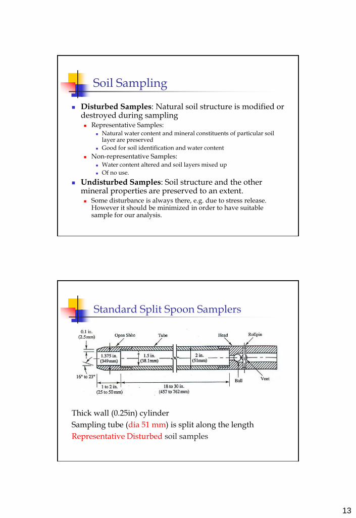
Standard Split Spoon Samplers
Thick wall (0.25in) cylinder
Sampling tube (dia 51 mm) is split along the length
Representative Disturbed soil samples

14
Shelby Tube (Thin-wall) Sampler
Thin wall (1/16in = 0.0625 in) sampling tube
Sampler pushed into the ground hydraulically
Sample extruded from tube and “Undisturbed” soil sample is obtained
Sealing of Sampling Tube
After removing the sampler from ground, it is sealed on both sides using melted wax to preserve moisture
15
Laboratory Test: Index Properties
Index Properties of soil:
Basic soil properties such as (a) Specific gravity (Gs)(b) Grain size distribution (dry/wet Sieve test, Hydrometer test), (c) Liquid Limit (LL), Plastic limit (PL) (d) OMC, Maximum Dry density(Compaction/Proctor test)(e) Permeability (Constant head/Falling head)(f) Relative Density (Minimum & Maximum density for cohesionless soils)
More tests for Problem soils: (a) Shrinkage Limit, Free swell, Swell pressure for Expansive soils(b) Pinhole test, Crumb test for Dispersive soils(c) Chemical Test (PH, Sulphite, Chloride, Iron etc) for soils (may affected with industrial waste or some other waste)(d) Furnace test for Organic Soils (peats etc)
“Representative Disturbed “soil samples are used to perform these tests.
Laboratory Test: Engineering Properties
Engineering Properties of soil:
Consolidation Properties (Oedometer setup)(i) Must to perform for Clayey soils; (ii) Soil parameters obtained: Cc,Cv,Cr, OCR, k
Shear Strength Properties(i) Direct Shear test (for cohesionless soil)(ii) Unconfined Compression test (for cohesive soil)
(iii) Triaxial test (for all soil types; cohesive, cohesionless)
Dynamic Properties(i) Cyclic Triaxial test(ii) Cyclic Simple Shear test(iii) Resonant Column test(iv) Bender Element test
“Undisturbed” soil samples are used to perform these tests.

16
Consolidation Test: Oedometer Test
Input: Vertical Load, Vertical Displacement
Output: Consolidation parameters (Cv, Cc & Cs); void ratio Vs overburden pressure curve
Direct Shear Test (Recommended for Cohesionless soils)
Input: Vertical Load, Vertical Displacement, Lateral Load Lateral Displacement
Output: shear strength, friction angle (f)

17
Unconfined Compression Test (UC test) (Recommended for Cohesive soils)
Input: Vertical Load, Vertical Displacement
Output: Shear Strength under Undrained Conditions (Su)
Triaxial Test:
Measures shear strength parameters of soil (shear strength properties: cohesion, friction angle)
Loading conditions : Static loading (compression is common)

18
Triaxial Testing Setup
Soil specimen
Triaxial setup
Control Panel
Input: Vertical Load, Vertical Displacement, Pore pressure, Cell pressure
Output: Shear Strength properties of soil under UU, CU, CD Conditions: friction angle (f), cohesion (c)
Triaxial & Cyclic Triaxial

19
Soil Properties
Monotonic Loading (Shear strength properties of soil)
Angle of Internal Friction (f)
Cohesion (c)
Dynamic Loading (Dynamic properties of soil)
Shear Modulus (G)
Damping Ratio (D)
Dynamic properties of Soil
Shear Modulus, G = .VS2
Shear wave velocity = VS (m/sec)
Mass density = (g/g) (Kg/m3)
Unit weight of soil = g (KN/m3)
Acceleration of gravity = g (m/sec2)
Damping, D = decay in energy
Shear Modulus (G) is measured in KN/m2 & Damping (D) in %

20
Dynamic properties of soil
Low Strain Amplitude test
For strains (10-6% to 10-4%)
Frequency range: 10 Hz to 200Hz
Vibratory loading (Rotating Machinery etc)
High Strain Amplitude test
For strains (10-4% to 10-2%)
Frequency range: 0.1 Hz to 2 Hz (in general)
Blast loading, Earthquake
Dynamic properties (Lab test)
High Strain Amplitude test
Cyclic Triaxial Test
Cyclic Direct Simple Shear Test
Low Strain Amplitude test
Resonant Column Test
Bender Element Test

21
Cyclic Triaxial Test (High strain amplitude test)
Dynamic properties of soil using Cyclic Triaxial system:
1. Shear Modulus (G)
2. Damping ratio (D)
Cyclic Triaxial Test
DDamping EModulus Young Dynamic
dStress Dynamic aStrain Axial

22
Cyclic Simple Shear Test (High strain amplitude test)
Digitally controlled Electro-mechanical actuators are used to apply the stress or strain controlled loading
Output: Shear modulus (G), Damping (D)
Cyclic Simple Shear Test
DDamping GusShearModul
gnShearStraisShearStres

23
Resonant Column Test (Low strain amplitude test)
The basic principle of the resonant column device is to excite one end of a confined cylindrical soil specimen in a fundamental mode of vibration by means of torsional or longitudinal excitation.
Once the fundamental mode of resonance frequency is established, measurements are made of the resonance frequency and amplitude of vibration from which wave propagation velocities and strain amplitudes are calculated using the theory of elasticity.
The Resonant Column Test provides laboratory values of Shear modulus (G) and Damping ratio (D).
Resonant Column Test (Low strain amplitude test)
(a) Specimen is excited at the bottom and the response is picked up at the top (velocity or acceleration)(b) Driving force is applied on the top. The response pickup is also placed on the top
With known value of the resonant frequency it is possible to back-calculate the velocity (vs or vl) of the wave propagation and thereby G or E
After measuring the resonant condition, the drive system is cut of and the specimen is brought to a state of free vibration. Damping is determined by observing the decay pattern

24
tiCt e)(
Acc.
ff
Resonant freq. f1
+
Sample Geometry
+
End restraint
+
Wave equation (torsion)
( 2
1220 2
T
sF
fHvG
Resonant Column Test:Determination of Shear Modulus of soil (G)
Resonant Column Test:Damping properties of soil (D
D = 1/2·D1

25
Bender Element Test (Low strain amplitude test)
Bender Elements (made by Piezoelectric material)
Bender Element Test (Low strain amplitude test)
Piezo-ceramic elements distort or bend when subjected to a change in voltage.
Two Piezoelectric bender elements are placed opposite one another and inserted a small distance into a soil sample. One bender element work as source and other as receiver.
The voltage in one element is varied creating shear waves through the sample, which are received by the opposite element. The input voltage, (created using a function generator) and the received signal are recorded continuously using an oscilloscope, allowing the travel time of the shear waves to be measured from which the dynamic elastic shear modulus (G) can be determined.
Bender elements provide a reliable, cost effective alternative to undertaking locally instrumented stress path triaxial tests and can be readily performed on unconfined samples in the laboratory.
26
Thank You