Geotechnical - Load and Resistance Factor Design · Geotechnical - Load and Resistance Factor...
67
Geotechnical - Load and Resistance Factor Design By Mir Zaheer, P.E., Geotechnical Engineer , INDOT Office of Geotechnical Engineering INDOT Structures Conference - 2010
Transcript of Geotechnical - Load and Resistance Factor Design · Geotechnical - Load and Resistance Factor...

Geotechnical - Load and Resistance Factor Design
By
Mir Zaheer, P.E.,Geotechnical Engineer ,
INDOT Office of Geotechnical Engineering
INDOT Structures Conference - 2010
MSE Walls
AASHTO Section 11FHWA GEC 11
FHWA-NHI-10-024 & 25

MSE Walls
In LRFD, the external and internal stability of the MSE wall is evaluated at all appropriate Limit states.
In the AASHTO-LRFD framework, there are four limit states, which represent distinct structural performance criteria: (1) strength limit states (2) Serviceability limit states (3) extreme event limit states (4) fatigue limit states
For most earth retaining system designs, the strength or service limit states control the design. For walls subject to earthquake or vessel/vehicle impact, the extreme limit states may control.

Design of MSE walls Using LRFD Methodology
Strength Limit States External Stability
Limiting Eccentricity Sliding Bearing Resistance
Internal Stability Tensile Resistance of
Reinforcement Pullout Resistance of
Reinforcement Structural Resistance of
face elements Structural resistance of
Face Element Connections
Service Limit States External Stability Vertical WALL Movements Lateral Wall Movements
Global Stability Overall Stability Compound Stability
Internal Stability is the responsibility of the manufacturer

LRFD for MSE Walls
Load Combinations Load Factors for Permanent Loads External Stability Resistance Factors

Loads and Combinations
Permanent Loads EH = Horizontal Earth Loads ES = Earth Surcharge Load EV = Vertical Pressure from
dead load of earth fill
Transient Loads CT = Vehicular collision force EQ = Earthquake Load LL = Vehicular Live Load LS = Live Load Surcharge
Load Combination Limit State
EHESEV
LLLS EQ CT
Strength I γP 1.75 -- --
Extreme Event I γP γEQ 1.0 --
Extreme Event II γP 0.5 -- 1.0
Service I 1.0 1.0 -- --
γp =Load factor for permanent loading. May subscript as γP-EV, γP-EH
γEQ = Load factor for live load applied simultaneously with seismic loads
Table 3.4.1-1 AASHTO 2007
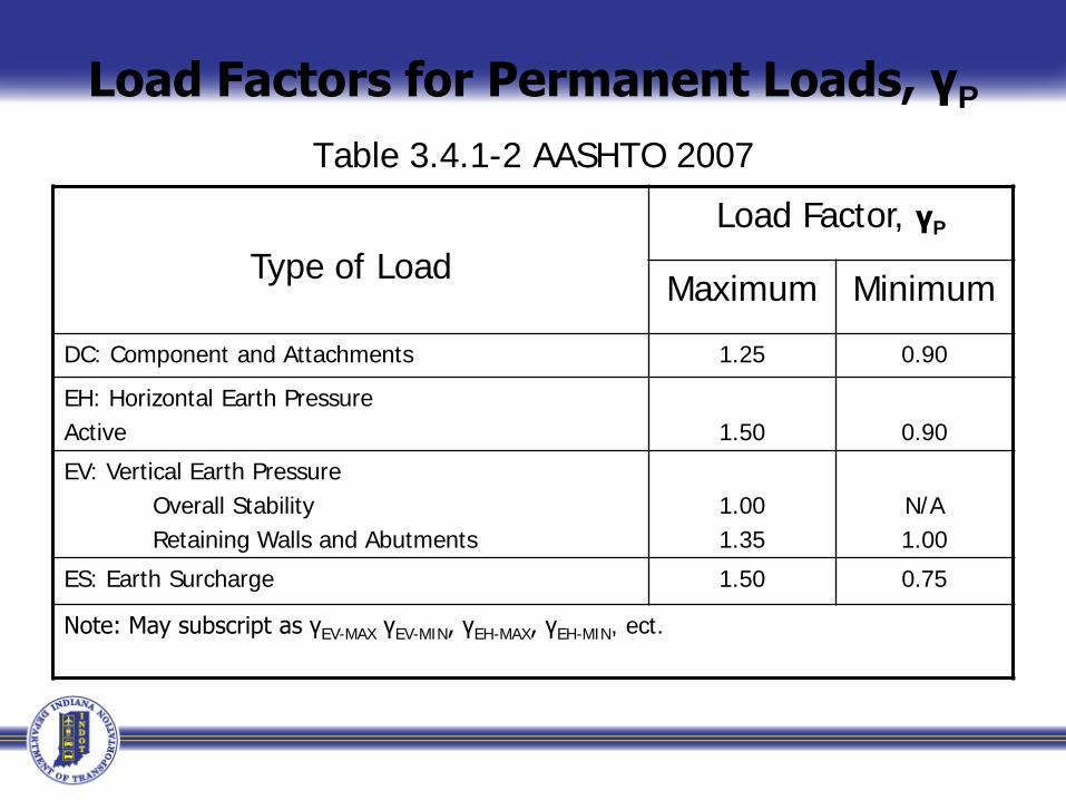
Load Factors for Permanent Loads, γP
Table 3.4.1-2 AASHTO 2007
Type of Load Load Factor, γP
Maximum Minimum
DC: Component and Attachments 1.25 0.90
EH: Horizontal Earth PressureActive 1.50 0.90
EV: Vertical Earth Pressure Overall Stability Retaining Walls and Abutments
1.001.35
N/A1.00
ES: Earth Surcharge 1.50 0.75
Note: May subscript as γEV-MAX γEV-MIN, γEH-MAX, γEH-MIN, ect.

External Stability Resistance Factors for MSE Walls
Stability Mode Conditions Resistance Factor, Φτ
Bearing Resistance None 0.65
Sliding None 1.0
Overall (Global) Stability
Where geotechnical parameters are well defined, and the slope does not support or contain a structural element
0.75
Where geotechnical parameters are based on limited information, or the slope contains or supports a structural element
0.65

MSE Wall Design Example

MSE Wall Design Example

MSE Wall Design Example

MSE Wall Design Example

MSE Wall Design Example

MSE Wall Design Example
CDR = Capacity To Demand Ratio

MSE Wall Design Example

MSE Wall Design Example
If the sliding, capacity demand ratio, CDR < 1, INCREASE the reinforcement length, L, and repeat the calculations.

General Foundation Design Flow Chart1. Establish Global Project Performance Requirements and Constraints
2. Define Preliminary Project Geotechnical Site Conditions
3. Determine Substructure Loads and Load Combinations at Foundation Level
4. Develop and Execute Subsurface Exploration and Laboratory Testing Program for Feasible Foundation System
5. Evaluate Information and Determine Foundation Systems for Further Evaluation
6. Deep Foundations Shallow Foundations
Without Ground Improvement
With Ground Improvement
Shallow Foundations
AASHTO SECTION 10.6FHWA – RC/TD -10-001
FHWA-NHI-05-094
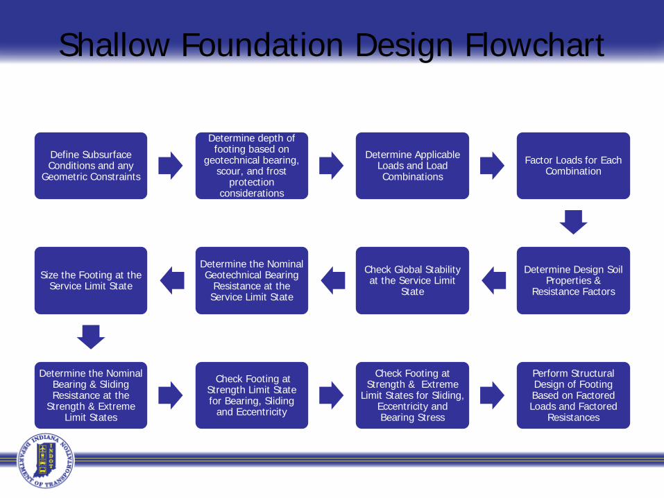
Shallow Foundation Design Flowchart
Define Subsurface Conditions and any
Geometric Constraints
Determine depth of footing based on
geotechnical bearing, scour, and frost
protection considerations
Determine Applicable Loads and Load Combinations
Factor Loads for Each Combination
Determine Design Soil Properties &
Resistance Factors
Check Global Stability at the Service Limit
State
Determine the Nominal Geotechnical Bearing
Resistance at the Service Limit State
Size the Footing at the Service Limit State
Determine the Nominal Bearing & Sliding Resistance at the
Strength & Extreme Limit States
Check Footing at Strength Limit State for Bearing, Sliding
and Eccentricity
Check Footing at Strength & Extreme
Limit States for Sliding, Eccentricity and Bearing Stress
Perform Structural Design of Footing Based on Factored Loads and Factored
Resistances
Limit States for Spread Footings
Design of a spread footing must provide adequate resistance against geotechnical and structural limit states, i.e., "failure“ modes. The geotechnical limit states includethe following: Strength limit state
Bearing resistance Limiting eccentricity Sliding

Strength Limit States
Sliding Limiting Eccentricity
Bearing Resistance

Service limit state Settlement Global stability
Extreme Event limit state Bearing resistance Limiting eccentricity Sliding

Service Limit States
Settlement Overall Stability

The structural design includes considerationof limit states for the following: • Flexural resistance (strength limit) • Shear resistance (strength limit) • Crack control (service limit)

Horizontal Deformations-Settlements & Rotations

Bearing resistance Chart

Design Resources

LRFD DESIGN - BASICS
Load factor combinations to obtain resulting maximum force effects on the foundations are needed for limit states checks.
This is done through structure modeling by varying the load factors over the specified range
Service Limit State I-Checks
Vertical deformation – Settlement Horizontal movements at the top of
foundation Rotations at the top of foundation Vertical and horizontal deformations under
scour at the Design flood, Q100 Settlements due to downdrag(AASHTO 10.5, 10.6, 10.7 & 10.8)

Requirements for LRFD Design
Tolerable vertical and horizontal deformations (movements) are established by the structural designer, based on structural tolerance to total and differential movements, rideability, and economy. (AASHTO 10.5.2.1)

Strength Limit States - Checks
Geotechnical lateral resistance of soil and rock Geotechnical axial compression resistance Geotechnical axial uplift resistanceAll the above for single and group foundations Structural resistance checks for axial, lateral and flexure Punching of foundation elements through stronger soil in
to weaker soilsAll the above resistances under scour at design flood, Q100 Axial resistance when downdrag occurs
(AASHTO 10.5, 10.6, 10.7 & 10.8)

Axial Geotechnical Resistance

Overall Stability
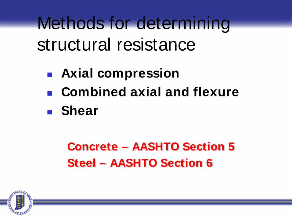
Methods for determining structural resistance Axial compression Combined axial and flexure Shear
Concrete – AASHTO Section 5 Steel – AASHTO Section 6

Structural Axial Failure Mode
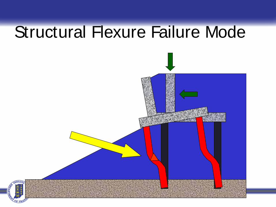
Structural Flexure Failure Mode

Structural Shear Failure Mode
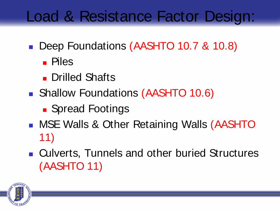
Load & Resistance Factor Design:
Deep Foundations (AASHTO 10.7 & 10.8) Piles Drilled Shafts
Shallow Foundations (AASHTO 10.6) Spread Footings
MSE Walls & Other Retaining Walls (AASHTO 11)
Culverts, Tunnels and other buried Structures (AASHTO 11)

Deep Foundations
Driven Piles - AASHTO 10.7Drilled Shafts - AASHTO 10.8
FHWA-NHI-05-094FHWA-NHI-10-016

6. Deep Foundations
7. Select Driven Pile Foundations for Further Evaluation
8. Select Static Analysis Method and Calculate Ultimate Axial Capacity vs. Depth
9. Identify Most Economical Pile Types from Ultimate Capacity vs. Depth Charts
10. Drivability of pile types to penetration depths and sufficient ultimate capacities
11. Select pile types, ultimate capacities, and pile penetration depths for group sizing
12. Evaluate Group axial, Lateral, and Rotational Capacities, Settlement, and performance of pile group configuration
Evaluate Other Deep Foundation Systems
i.e. Drilled Shafts
General Deep Foundation Design Flow Chart for Driven Piles
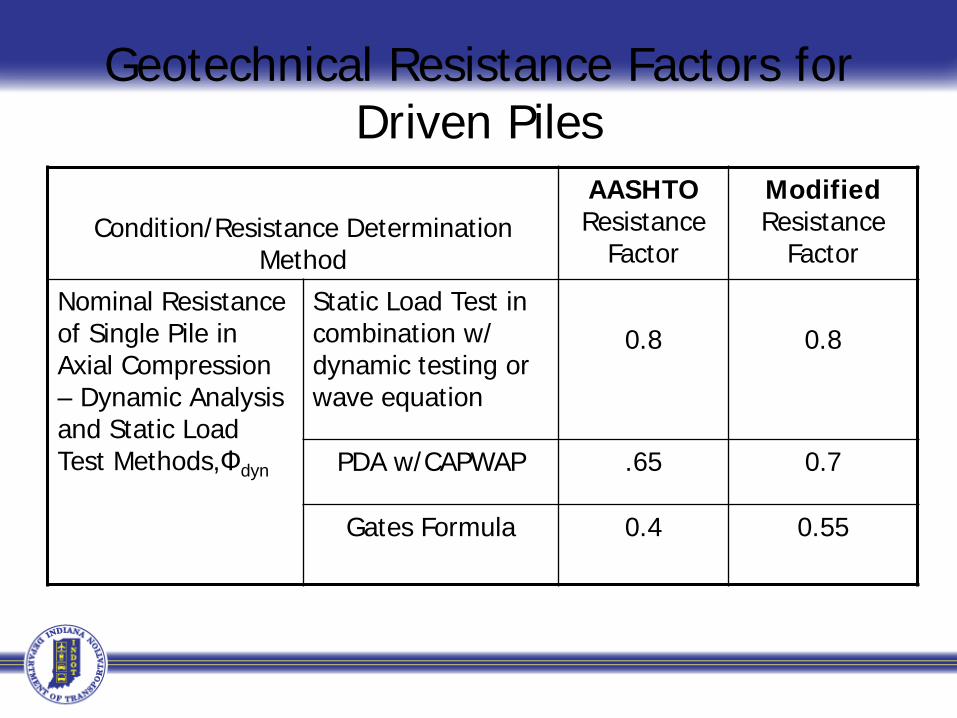
Geotechnical Resistance Factors for Driven Piles
Condition/Resistance Determination Method
AASHTO Resistance
Factor
ModifiedResistance
Factor
Nominal Resistance of Single Pile in Axial Compression – Dynamic Analysis and Static Load Test Methods,Φdyn
Static Load Test in combination w/ dynamic testing or wave equation
0.8 0.8
PDA w/CAPWAP .65 0.7
Gates Formula 0.4 0.55
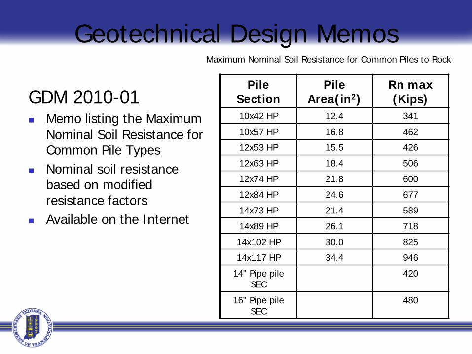
Geotechnical Design Memos
GDM 2010-01 Memo listing the Maximum
Nominal Soil Resistance for Common Pile Types
Nominal soil resistance based on modified resistance factors
Available on the Internet
Pile Section
Pile Area(in2)
Rn max (Kips)
10x42 HP 12.4 341
10x57 HP 16.8 462
12x53 HP 15.5 426
12x63 HP 18.4 506
12x74 HP 21.8 600
12x84 HP 24.6 677
14x73 HP 21.4 589
14x89 HP 26.1 718
14x102 HP 30.0 825
14x117 HP 34.4 946
14" Pipe pile SEC
420
16" Pipe pile SEC
480
Maximum Nominal Soil Resistance for Common Piles to Rock

Horizontal Displacement (P-y method)
Ht
Qt
MtyP
y
yPropertiesA, E, I

P
y
Pm * P
P
Spacing (S) Row 1 Row 2 Row 33D 0.7 0.5 0.355D 1.0 0.85 0.7
P-multiplier (Pm)D
S
From Table 10.7.2.4-1

Example Pile Design -Pier
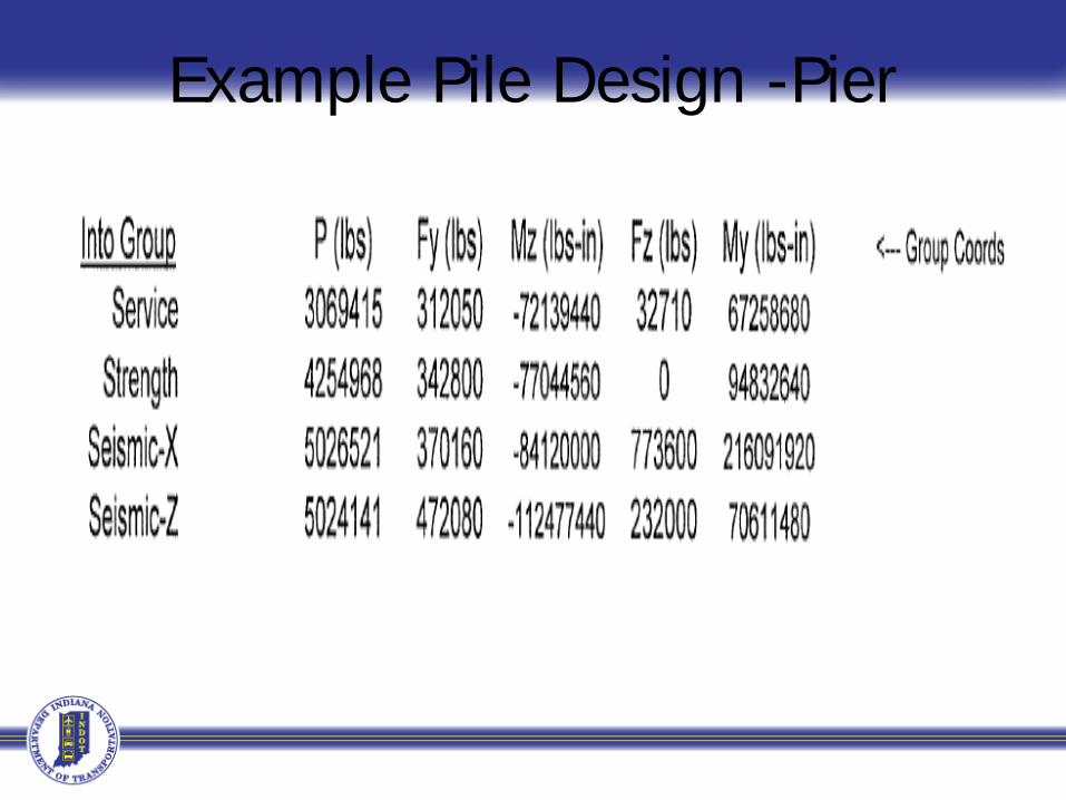
Example Pile Design -Pier

EXAMPLE PILE LOADS
Strength Extreme Values in Pile Load Table
Factored Loads QF
200 K 300 K 210 K
Resistance Factor φ
0.7 1.0 0.7
Nominal Soil Resistance Rn
286 K 300 K 300 K
The extreme loads control the design. Hence the pile shall be driven to a nominal capacity that provides the required controlling factored loads.

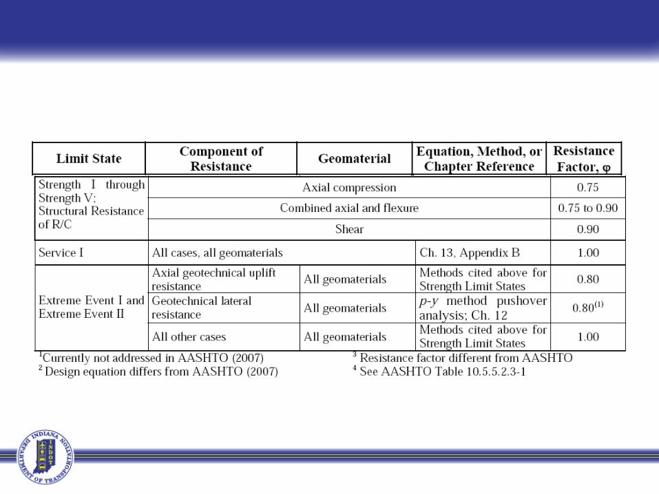
Limitations of Resistance Factors:AASHTO LRFD BRIDGE DESIGN SPECIFICATIONS 10.5.5.2.3
The selection of the target reliability assumes a significant amount of redundancy in the foundation system is present, which is typical for pile groups containing at least five piles in the group. For smaller groups and single piles, less redundancy will be present. These smaller pile groups that lack redundancy. Therefore, the resistance factors specified in Table 1 should be reduced to account for reduced redundancy.

Drilled Shafts
AASHTO 10.7 AND 10.8FHWA GEC 10
FHWA-NHI-10-016

6. Deep Foundations
7. Select Drilled Shaft Foundations for Further Evaluation
8. Define Subsurface Profile for analysis
9. Determine Resistance Factors for Design
10. Establish Minimum Diameter and Depth for Lateral Loads
11. Establish Diameter and Depth for Axial Loads
12. Finalize Structural Design of the Drilled Shafts and Connection to Structure (or cap)
Evaluate Other Deep Foundation Systems i.e.
Piles
General Deep Foundation Design Flow Chart for Drilled Shafts

10. Establish Minimum Diameter and Depth for Lateral Loads
10.1 Refine Detailed Subsurface Profiles as needed for each Lateral Load Case, including scour, liquefaction, fill, ect.
10.2 Select Trial Length and Diameter
10.3 Analyze Geotechnical Strength Limit State using Factored Loads (for each case)
Check Stability against Pushover Failure
Yes. 10.4 Analyze Preliminary Structural Strength Limit State for Flexure using Factored Loads
Check Moment Capacity with 1 to 2% Longitudinal Reinforcement
Yes.10.5 Analyze Service Limit State (Deformations) using Unfactored Loads
Check: Deformations Acceptable
Yes. 10.6 Define Minimum Pile Length and Diameter based on analysis No . Return to 10.2 and Revise Design
No. Revise Diameter and repeat steps starting at 10.2
No. Revise Length and repeat steps starting at 10.2
Lateral Loads Design Process For Drilled Shafts

11.1 Idealized Geomaterial Layer Profiles
11.2 Review Limit States and Factored Axial Force Effects
11.3 Assign Appropriate Geomaterial Properties to each Subsurface Layer
11.4 Select Trial Lengths and Diameters
11.5 Establish Nominal Side and Base Resistances
11.6 Evaluate Trial Design for LRFD Strength Limit States
Yes. 11.7 Evaluate Trial Design for LRFD Service Limit States
Yes. Design Complete No. Return to 11.4 and Redesign
No. Return to 11.4 and Redesign
Establish Minimum Depths and Diameters for Axial Loads for Drilled Shafts

Geotechnical Resistance FactorsDrilled Shafts
Method φComp φTen
α - Method (side) 0.55 0.45β - Method (side) 0.55 0.45Clay or Sand (tip) 0.5Rock (side) 0.55 0.45Rock (tip) 0.55Group (sand or clay) 0.55 0.45Load Test 0.7
AASHTO Table 10.5.5.2.3-1
Presenter
Presentation Notes
The resistance factors are provided for each method in AASHTO section 10.5

Summary of Resistance Factors for LRFD Design of Drilled Shaft Foundations


Drilled Shaft Resistance in Rock
Side Resistance
Tip Resistance
Total ResistanceA
BCD
Qb
QS
QR = φQn = φqbQb + φqsQs
Displacement
Res
ista
nce

Questions?

EXAMPLE CALCSLimit State Nominal
Load (kip)ResistanceFactor (φ)
Factored Load (kip)
MaximumService I
183.6 1.00 183.6
Maximum Strength I
253.2 0.70 177.5
Maximum Extreme I
356.9 1.00 356.9
Extreme I is controlling. The pile is driven to this maximum nominal load in the pile load Table