GEOTECHNICAL INVESTIGATION KAWAINUI MARSH …
31
GEOTECHNICAL INVESTIGATION KAWAINUI MARSH RESTORATION OF ENDANGERED HABITATS & WETLANDS KAHANAIKI SITE ACCESS ROAD KAILUA, OAHU, HAWAII DLNR JOB NO. D00CO44A for AECOM HIRATA & ASSOCIATES, INC. W.O. 19-6200 December 6, 2019
Transcript of GEOTECHNICAL INVESTIGATION KAWAINUI MARSH …

GEOTECHNICAL INVESTIGATION KAWAINUI MARSH RESTORATION OF ENDANGERED HABITATS & WETLANDS KAHANAIKI SITE ACCESS ROAD KAILUA, OAHU, HAWAII DLNR JOB NO. D00CO44A
for
AECOM HIRATA & ASSOCIATES, INC. W.O. 19-6200 December 6, 2019


Hirata & Associates, Inc. W.O. 19-6200
TABLE OF CONTENTS
INTRODUCTION .....................................................................................................1
PROJECT CONSIDERATIONS ...............................................................................2 SITE CONDITIONS ..................................................................................................2 SOIL CONDITIONS .................................................................................................2 CONCLUSIONS AND RECOMMENDATIONS ....................................................3 Pavement Design ...........................................................................................3 Site Grading ...................................................................................................4 ADDITIONAL SERVICES .......................................................................................5 LIMITATIONS ..........................................................................................................6
Hirata & Associates, Inc. W.O. 19-6200
APPENDICES
APPENDIX A Description of Field Investigation ................................................ Plates A1.1 and A1.2 Location Map ................................................................................ Plate A2.1 Boring Location Plan .................................................................... Plate A2.2 Boring Log Legend ....................................................................... Plate A3.1 Unified Soil Classification System ............................................... Plate A3.2 Boring Logs .................................................................................. Plates A4.1 through A4.4 APPENDIX B Description of Laboratory Testing ................................................ Plates B1.1 and B1.2 Consolidation Test Reports ........................................................... Plates B2.1 and B2.2 Modified Proctor Test Reports ...................................................... Plates B3.1 and B3.2 CBR Stress Penetration Test Reports ........................................... Plates B4.1 and B4.2

December 6, 2019 W.O. 19-6200
Hirata & Associates, Inc. Page 1
GEOTECHNICAL INVESTIGATION KAWAINUI MARSH RESTORATION OF
ENDANGERED HABITATS & WETLANDS KAHANAIKI SITE ACCESS ROAD
KAILUA, OAHU, HAWAII DLNR JOB NO. D00CO44A
INTRODUCTION
This report presents the results of our geotechnical investigation performed for the
proposed improvements to the Kahanaiki Site access road on the north side of
Kawainui Marsh. Our scope of services for this study included the following:
• A visual reconnaissance of the site and its vicinity to observe existing conditions which may affect the project. The general location of the project site is shown on the enclosed Location Map, Plate A2.1.
• A review of available in-house soils information pertinent to the site and
the proposed project. • Drilling and sampling four exploratory borings to depths of about 10.5
feet. A description of our field investigation is summarized on Plates A1.1 and A1.2. The approximate exploratory boring locations are shown on the enclosed Boring Location Plan, Plate A2.2, and the soils encountered in the borings are described on the Boring Logs, Plates A4.1 through A4.4.
• Laboratory testing of selected soil samples. Testing procedures are
presented in the Description of Laboratory Testing, Plates B1.1 and B1.2. Test results are presented on the Boring Logs (Plates A4.1 through A4.4), the Unified Soil Classification System (Plate A3.2), Consolidation Test reports, (Plates B2.1 and B2.1), Modified Proctor Test reports (Plates B3.1 and B3.2), and CBR Stress Penetration Test reports (Plates B4.1and B4.2).
• Engineering analyses of the field and laboratory data. • Preparation of this report presenting geotechnical recommendations for the
design of flexible and rigid pavement, gravel roads, subgrade requirements for use of geoblock and geopave support systems, and site grading.

December 6, 2019 W.O. 19-6200
Hirata & Associates, Inc. Page 2 PROJECT CONSIDERATIONS
Information regarding the proposed project was provided by your office.
The project will consist of improvements to the Kahanaiki Site access road from
Kapaa Quarry Road. The new maintenance road will include a large staging area
near the entrance, having plan dimensions of about 100 by 87 feet, then extending
for a length of about 330 feet in a northerly direction. Another staging area is
proposed at the end of the access road having plan dimensions of about 30 by 40
feet.
The proposed access road will include two steeper sections. The first section will
be approximately 28 feet in length with a proposed grade of 43 percent. The
second section will include a length of about 90 feet with a 12 percent grade.
Several roadway surfaces are being considered including gravel roads, flexible
and rigid pavements, and the use of porous pavement such as geoblock and
geopave support systems.
SITE CONDITIONS
The proposed Kawainui Marsh Kahanaiki Site access road is located across from
the entrance to the Le Jardin Academy. The proposed roadway alignment is
heavily overgrown with trees and shrubs. The site generally slopes from Kapaa
Quarry Road with elevations ranging from about +67 to +58, where the first
staging area is proposed, to an elevation of about +50 where the second staging
area is located.
SOIL CONDITIONS
All borings encountered a mottled reddish brown to brown clayey silt in a
medium stiff to stiff condition from the surface down to the maximum depths
drilled of about 10.5 feet. The clayey silt was mixed with sand and was in a moist
condition. Neither groundwater nor seepage water was encountered.
December 6, 2019 W.O. 19-6200
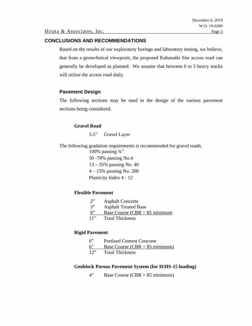
Hirata & Associates, Inc. Page 3 CONCLUSIONS AND RECOMMENDATIONS
Based on the results of our exploratory borings and laboratory testing, we believe,
that from a geotechnical viewpoint, the proposed Kahanaiki Site access road can
generally be developed as planned. We assume that between 0 to 5 heavy trucks
will utilize the access road daily.
Pavement Design
The following sections may be used in the design of the various pavement
sections being considered.
Gravel Road
5.5” Gravel Layer
The following gradation requirements is recommended for gravel roads. 100% passing ¾” 50 -78% passing No.4 13 – 35% passing No. 40 4 – 15% passing No. 200 Plasticity Index 4 - 12
Flexible Pavement
2” Asphalt Concrete 3” Asphalt Treated Base 6” Base Course (CBR = 85 minimum
11” Total Thickness
Rigid Pavement
6” Portland Cement Concrete 6" Base Course (CBR = 85 minimum)
12” Total Thickness
Geoblock Porous Pavement System (for H/HS-15 loading)
4” Base Course (CBR = 85 minimum)

December 6, 2019 W.O. 19-6200
Hirata & Associates, Inc. Page 4
Geopave Porous Pavement System (for H/HS-10 loading)
2” Base Course
Utilize high strength non-woven geotextile fabric for slopes greater than 7 to 10
percent.
Site Grading Slope Gradients - All cut and fill slopes should be stable at slope gradients of
2H:1V or flatter. In the event that cut and fill slopes exceed 15 feet in height, the
slopes should include benches at least 8 feet in width. The benches should be
constructed at intervals not exceeding 15 feet in vertical height. All slopes should
be planted as soon as practical upon completion of grading to reduce the effects of
erosion and weathering.
Fill slopes should be constructed from the bottom up. The fill should be
continually benched into existing slopes as the fill is brought up in lifts. The
benches should extend into competent material and be wide enough for
compaction equipment to work effectively. Fill slopes should be constructed by
overfilling and cutting back to the design slope gradient to obtain a well-
compacted slope face.
Site Preparation - The project site should be cleared of all vegetation and other
deleterious material. In areas requiring fill placement, the exposed subgrade
should be scarified to a minimum depth of 6 inches, and compacted to a minimum
95 percent compaction as determined by ASTM D 1557.
Temporary cuts into the onsite soils should be stable at gradients from 1H:1V or
flatter. However, it should be the Contractor's responsibility to conform to all
OSHA safety standards for excavations.

December 6, 2019 W.O. 19-6200
Hirata & Associates, Inc. Page 5
Onsite Fill Material - The onsite soils may be reused in compacted fills and
backfills, provided all rock fragments larger than 3 inches in maximum dimension
are removed.
As a precautionary measure, the moisture content of the clayey silt should be
maintained at about 2 percent above the optimum moisture content during
recompaction.
Imported Fill Material - Imported structural fill should be well-graded, non-
expansive granular material. Specifications for imported granular structural fill
should indicate a maximum particle size of 3 inches, and state that between 8 and
20 percent of soil by weight shall pass the #200 sieve. In addition, the plasticity
index (P.I.) of that portion of the soil passing the #40 sieve shall not be greater
than 10. Imported structural fill should have a CBR expansion value no greater
than 1.0 percent and a minimum CBR value of 15 percent, when tested in
accordance with ASTM D 1883.
Compaction - Imported structural fill and onsite soils should be placed in
horizontal lifts restricted to eight inches in loose thickness and compacted to a
minimum 95 percent compaction as determined by ASTM D 1557.
Fill placed in areas which slope steeper than 5H:1V should be continually keyed
and benched as the fill is brought up in lifts.
Backfill over Drainage Culverts – Above the crushed rock section and up to
finish subgrade elevation, the onsite soils, imported granular fill, or soils
conforming to Section 16 of the Standard Specification for Public Works
Construction for the City and County of Honolulu may be used. Backfill should
be placed in level lifts limited to 8 inches in loose thickness. Backfill material
placed above the crushed rock section up to a depth of 3 feet below finish
subgrade should be compacted to a minimum 90 percent compaction as
determined by ASTM D 1557. Within 3 feet of finish subgrade, backfill material

December 6, 2019 W.O. 19-6200
Hirata & Associates, Inc. Page 6
should be compacted to a minimum 95 percent compaction as determined by
ASTM D 1557.
ADDITIONAL SERVICES
We recommend that we perform a general review of the final design plans and
specifications. This will allow us to verify that the pavement design and site
grading recommendations have been properly interpreted and implemented in the
design plans and construction specifications.
For continuity, we recommend that we be retained during construction to (1)
review and/or perform laboratory testing on import borrow to determine its
acceptability for use in compacted fills, (3) observe structural fill placement and
perform compaction testing, and (4) provide geotechnical consultation as
required.
Our services during construction will allow us to verify that our recommendations
are properly interpreted and included in construction, and if necessary, to make
modifications to those recommendations, thereby reducing construction delays in
the event subsurface conditions differ from those anticipated.
LIMITATIONS
The boring logs indicate the approximate subsurface soil conditions encountered
only at those times and locations where our borings were made, and may not
represent conditions at other times and locations.
This report was prepared specifically for AECOM and their sub-consultants for
design of the proposed improvements to the Kahanaiki Site access road for the
Kawainui Marsh project. The boring logs, laboratory test results, and
recommendations presented in this report are for design purposes only, and are
not intended for use in developing cost estimates by the contractor.


APPENDIX A
FIELD INVESTIGATION

December 6, 2019 W.O. 19-6200
Hirata & Associates, Inc. Plate A1.1
DESCRIPTION OF FIELD INVESTIGATION GENERAL
The site was explored on September 26, 2019, by performing a visual
reconnaissance of the site and drilling four exploratory borings to maximum
depths of about 10.5 feet with a RAD track-mounted drill rig.
During drilling operations, the soils were continuously logged by our field
engineer and classified by visual examination in accordance with the Unified Soil
Classification System. The boring logs indicate the depths at which the soils or
their characteristics change, although the change could actually be gradual. If the
change occurred between sample locations, the depth was interpreted based on
field observations. Classifications and sampling intervals are shown on the boring
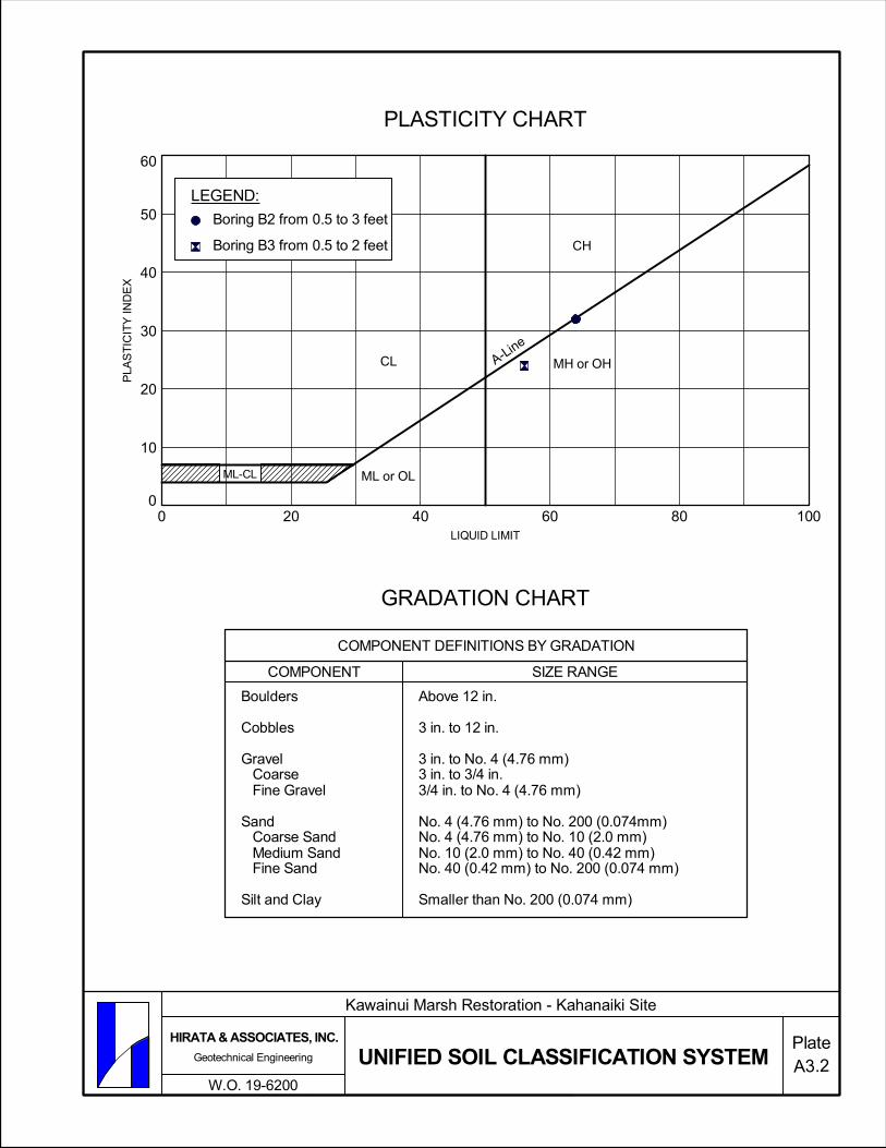
logs. A Boring Log Legend is presented on Plate A3.1, while the Unified Soil
Classification System is shown on Plate A3.2. The soils encountered are logged
on Plates A4.1 through A4.4.
Boring locations were selected by and staked out in the field by AECOM
personnel. Surface elevations at boring locations were estimated based on the
Topographic Survey Map provided by AECOM. The accuracy of the boring
locations shown on Plate A2.2 and the boring elevations shown on Plates A4.1
through A4.3 are therefore approximate, in accordance with the field methods
used.
SOIL SAMPLING Representative soil samples were recovered from the borings for selected
laboratory testing and analyses. Representative samples were recovered by
driving a 3-inch O.D. split tube sampler a total of 18 inches with a 140-pound
hammer dropped from a height of 30 inches. The number of blows required to
drive the samplers the final 12 inches are recorded at the appropriate depths on the
boring logs, unless noted otherwise. Bulk soil samples were recovered from

December 6, 2019 W.O. 19-6200
Hirata & Associates, Inc. Plate A1.2
boring B3 at a depth of about 0.5 to 3 feet below grade, and from boring B4 at
depths of about 0.5 to 2 feet.

Reference: Bryan's Sectional Maps, 2008 Edition(Copyright J.R. Clere, used with permission)
PlateA2.1
Kawainui Marsh Restoration - Kahanaiki Site
W.O. 19-6200
Geotechnical Engineering
HIRATA & ASSOCIATES, INC.
LOCATION MAP
AutoCAD SHX Text
PROJECT SITE

Approximate location of borings
LEGEND:
1" = 40'
GRAPHIC SCALE:200 FT.8040
W.O. 19-6200
Kawainui Marsh Restoration - Kahanaiki Site
BORING LOCATION PLAN A2.2
HIRATA & ASSOCIATES, INC.
Geotechnical EngineeringPlate

Kawainui Marsh Restoration - Kahanaiki Site
W.O. 19-6200
Inorganic silts, micaceous or diatomaceous finesandy or silty soils, elastic silts.
Peat and other highly organic silts.
MAJOR DIVISIONS
GM
CORAL
Poorly graded gravels or gravel-sand mixtures, littleor no fines.
Silty gravels, gravel-sand-silt mixtures.
Clayey gravels, gravel-sand-clay mixtures.
MH
CH
HIGHLY ORGANIC SOILS
FORMATIONS
Inorganic clays of high plasticity, lean clays.
Core Sample
OH
FRESH TO MODERATELY WEATHERED BASALT
Well graded gravels, gravel-sand mixtures, little orno fines.
Inorganic clays of high plasticity, fat clays.
COARSEGRAINED
SOILS(More than50% of thematerial is
LARGER thanNo. 200
sieve size.)
FINEGRAINED
SOILS(More than50% of thematerial is
SMALLER thanNo. 200
sieve size.)
SANDS(More than
50% ofcoarse
fraction isSMALLERthan the
No. 4sieve size.)
GRAVELS(More than
50% ofcoarse
fraction isLARGER than
the No. 4sieve size.)
CLEANGRAVELS(Little or no
fines.)
CLEANSANDS
(Little or nofines.)
SANDSWITH FINES(Appreciableamt. of fines.)
SILTS AND CLAYS(Liquid limit LESS than 50.)
SILTS AND CLAYS(Liquid limit GREATER
than 50.)
GW
GP
VOLCANIC TUFF / HIGHLY TO COMPLETELYWEATHERED BASALT
Well graded sands, gravelly sands, little or no fines.
Poorly graded sands or gravelly sands, little or nofines.
Silty sands, sand-silt mixtures.
Clayey sands, sand-clay mixtures.
TYPICAL NAMESGROUPDIVISIONS
PT
GC
SW
SP
SM
SC
ML
CL
OL
SAMPLE DEFINITION
PlateBORING LOG LEGEND
GRAVELSWITH FINES(Appreciableamt. of fines.)
3" O.D. Split Tube Sampler
2" O.D. Standard Split Spoon Sampler RQD: Rock Quality DesignationShelby Tube
Organic silts and organic silty clays of low plasticity.
Organic clays of medium to high plasticity, organicsilts.
Water Table
Inorganic silts and very fine sands, rock flour, silty orclayey fine sands or clayey silts with slight plasticity.
A3.1Geotechnical Engineering
HIRATA & ASSOCIATES, INC.
0
10
20
30
40
50
60
0 20 40 60 80 100
HIRATA & ASSOCIATES, INC.
Geotechnical Engineering
W.O. 19-6200
Kawainui Marsh Restoration - Kahanaiki Site
LIQUID LIMIT
ML-CL
PLASTICITY CHART
GRADATION CHART
Boulders
Cobbles
Gravel Coarse Fine Gravel
Sand Coarse Sand Medium Sand Fine Sand
Silt and Clay
Above 12 in.
3 in. to 12 in.
3 in. to No. 4 (4.76 mm)3 in. to 3/4 in.3/4 in. to No. 4 (4.76 mm)
No. 4 (4.76 mm) to No. 200 (0.074mm)No. 4 (4.76 mm) to No. 10 (2.0 mm)No. 10 (2.0 mm) to No. 40 (0.42 mm)No. 40 (0.42 mm) to No. 200 (0.074 mm)
Smaller than No. 200 (0.074 mm)
COMPONENT SIZE RANGE
COMPONENT DEFINITIONS BY GRADATION
PLA
ST
ICIT
Y IN
DE
X
CL A-Line
MH or OH
A3.2
CH
ML or OL
PlateUNIFIED SOIL CLASSIFICATION SYSTEM
LEGEND:
Boring B2 from 0.5 to 3 feet
Boring B3 from 0.5 to 2 feet

25
15
16
21
98
80
83
80
21
30
27
27
Clayey SILT (MH) - Mottled reddish brown, moist, stiff,sandy
End boring at 10.5 feet.
Neither groundwater nor seepage water encountered.
59.0 ±R
QD
(%
)
BLO
WS
PE
R F
OO
T
DRIVING WT.
DE
PT
H(f
t)
DROP 9/26/19
GEOTECHNICAL ENGINEERING
9/26/19
PROJECT NAME Kawainui Marsh Restoration - Kahanaiki Site
B1
END DATE
START DATE
SURFACE ELEV.
WORK ORDER NO. 19-6200
DR
Y D
EN
SIT
Y(p
cf)
MO
IST
UR
EC
ON
TE
NT
(%
)
BORING LOG
Boring No.
30 in.
CO
RE
RE
CO
VE
RY
(%
)
SA
MP
LE
140 lb.
GR
AP
HIC
LOG
RE
MA
RK
S/
SA
MP
LE N
O.
HIRATA & ASSOCIATES, INC.
Plate A4.1
MATERIAL DESCRIPTION
5
10
15
20
25
30
35
46
21
17
29
93
83
81
93
27
26
27
24
Consolidationtest
Clayey SILT (MH) - Mottled brown, moist, stiff, sandy
End boring at 10.5 feet.
Neither groundwater nor seepage water encountered.
60.2 ±R
QD
(%
)
BLO
WS
PE
R F
OO
T
DRIVING WT.
DE
PT
H(f
t)
DROP 9/26/19
GEOTECHNICAL ENGINEERING
9/26/19
PROJECT NAME Kawainui Marsh Restoration - Kahanaiki Site
B2
END DATE
START DATE
SURFACE ELEV.
WORK ORDER NO. 19-6200
DR
Y D
EN
SIT
Y(p
cf)
MO
IST
UR
EC
ON
TE
NT
(%
)
BORING LOG
Boring No.
30 in.
CO
RE
RE
CO
VE
RY
(%
)
SA
MP
LE
140 lb.
GR
AP
HIC
LOG
RE
MA
RK
S/
SA
MP
LE N
O.
HIRATA & ASSOCIATES, INC.
Plate A4.2
MATERIAL DESCRIPTION
5
10
15
20
25
30
35
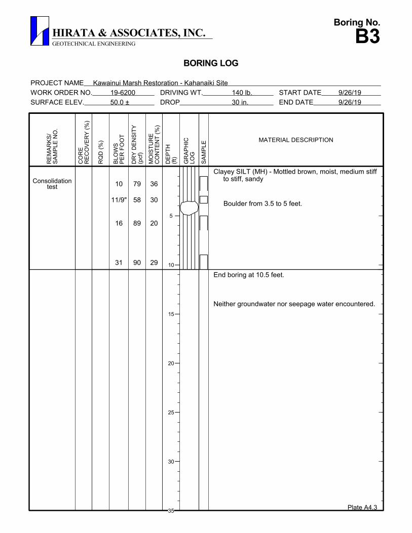
10
11/9"
16
31
79
58
89
90
36
30
20
29
Boulder from 3.5 to 5 feet.
Consolidationtest
Clayey SILT (MH) - Mottled brown, moist, medium stiffto stiff, sandy
End boring at 10.5 feet.
Neither groundwater nor seepage water encountered.
50.0 ±R
QD
(%
)
BLO
WS
PE
R F
OO
T
DRIVING WT.
DE
PT
H(f
t)
DROP 9/26/19
GEOTECHNICAL ENGINEERING
9/26/19
PROJECT NAME Kawainui Marsh Restoration - Kahanaiki Site
B3
END DATE
START DATE
SURFACE ELEV.
WORK ORDER NO. 19-6200
DR
Y D
EN
SIT
Y(p
cf)
MO
IST
UR
EC
ON
TE
NT
(%
)
BORING LOG
Boring No.
30 in.
CO
RE
RE
CO
VE
RY
(%
)
SA
MP
LE
140 lb.
GR
AP
HIC
LOG
RE
MA
RK
S/
SA
MP
LE N
O.
HIRATA & ASSOCIATES, INC.
Plate A4.3
MATERIAL DESCRIPTION
5
10
15
20
25
30
35

51
32
21
13
89
73
84
74
26
30
28
36Grading to medium stiff.
Clayey SILT (MH) - Reddish brown, moist, stiff, sandy
End boring at 10.5 feet.
Neither groundwater nor seepage water encountered.
41.0 ±R
QD
(%
)
BLO
WS
PE
R F
OO
T
DRIVING WT.
DE
PT
H(f
t)
DROP 9/26/19
GEOTECHNICAL ENGINEERING
9/26/19
PROJECT NAME Kawainui Marsh Restoration - Kahanaiki Site
B4
END DATE
START DATE
SURFACE ELEV.
WORK ORDER NO. 19-6200
DR
Y D
EN
SIT
Y(p
cf)
MO
IST
UR
EC
ON
TE
NT
(%
)
BORING LOG
Boring No.
30 in.
CO
RE
RE
CO
VE
RY
(%
)
SA
MP
LE
140 lb.
GR
AP
HIC
LOG
RE
MA
RK
S/
SA
MP
LE N
O.
HIRATA & ASSOCIATES, INC.
Plate A4.4
MATERIAL DESCRIPTION
5
10
15
20
25
30
35

APPENDIX B
LABORATORY TESTING
December 6, 2019 W.O. 19-2600
Hirata & Associates, Inc. Plate B1.1
DESCRIPTION OF LABORATORY TESTING CLASSIFICATION
Field classification was verified in the laboratory in accordance with the Unified
Soil Classification System. Laboratory classification was determined by visual
examination and Atterberg Limit tests. The final classifications are shown at the
appropriate locations on the Boring Logs, Plates A4.1 through A4.4 and on the
Unified Soil Classification System, Plate A3.2.
MOISTURE-DENSITY
Representative samples were tested for field moisture content and dry unit weight.
The dry unit weight was determined in pounds per cubic foot while the moisture
content was determined as a percentage of dry weight. Representative samples
were obtained using a 3-inch O.D. split tube sampler. Test results are shown at
the appropriate depths on the Boring Logs, Plates A4.1 through A4.4.
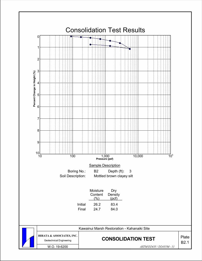
CONSOLIDATION Selected representative samples were tested for their consolidation characteristics.
The test samples were 2.42 inches in diameter and 1 inch high. Porous stones
were placed in contact with the top and bottom of the test samples to permit
addition and release of pore fluid. Loads were then applied in several increments
in a geometric progression, and the resulting deformations recorded at selected
time intervals. Test results are plotted on the Consolidation Test Reports, Plates
B2.1 and B2.2.
PROCTOR TEST
Modified Proctor tests were performed in general accordance with ASTM D 1557
on bulk soil samples obtained from boring B3 at depths between 0.5 to 3 feet
below grade, and from boring B4 at depths between 0.5 to 2 feet below grade.
The test is used to determine the optimum moisture content at which the soil
compacts to 100 percent dry density. Results are shown on Plates B3.1 and B3.2.
December 6, 2019 W.O. 19-2600
Hirata & Associates, Inc. Plate B1.2 CALIFORNIA BEARING RATIO TESTS
CBR tests were performed in general accordance with ASTM D 1883 on bulk
samples obtained from boring B3 at depths between 0.5 and 3 feet below grade,
and from boring B4 at depths between 0.5 and 2 feet below grade. The tests are
used to evaluate the relative quality of subgrade soils to be used in the design of
pavements and roadway support systems. Results are shown on Plates B4.1 and
B4.2.
0
1
2
3
4
5
6
7
8
9
1010 100 1,000 10,000 105
PlateB2.1
CONSOLIDATION TEST
Per
cen
t C
han
ge
in H
eig
ht
(%)
Consolidation Test Results
ASTM D2435 / D2435M - 11
FinalInitial
Soil Description:Boring No.:
MoistureContent
(%)
DryDensity
(pcf)
Depth (ft): 3Mottled brown clayey siltB2
24.7 26.2 83.4
84.0
Sample Description
Pressure (psf)
Kawainui Marsh Restoration - Kahanaiki Site
W.O. 19-6200
Geotechnical Engineering
HIRATA & ASSOCIATES, INC.

0
1
2
3
4
5
6
7
8
9
1010 100 1,000 10,000 105
PlateB2.2
CONSOLIDATION TEST
Per
cen
t C
han
ge
in H
eig
ht
(%)
Consolidation Test Results
ASTM D2435 / D2435M - 11
FinalInitial
Soil Description:Boring No.:
MoistureContent
(%)
DryDensity
(pcf)
Depth (ft): 1Mottled brown clayey siltB3
32.9 35.8 79.4
81.7
Sample Description
Pressure (psf)
Kawainui Marsh Restoration - Kahanaiki Site
W.O. 19-6200
Geotechnical Engineering
HIRATA & ASSOCIATES, INC.

70
80
90
100
110
10 20 30 40 50
Dry
Uni
t Wei
ght (
PC
F)
Description:Location:Soil Data
Test Results
%
Mottled brown clayey silt
PlateB3.1
ASTM D1557
Moisture Content (%)
Optimum Moisture Content:Maximum Dry Density: 104.5
20.5
Boring B3 from 0.5 to 3 feet
PCF
MODIFIED PROCTOR TEST
Kawainui Marsh Restoration - Kahanaiki Site
W.O. 19-6200
Geotechnical Engineering
HIRATA & ASSOCIATES, INC.

80
90
100
110
10 20 30 40
Dry
Uni
t Wei
ght (
PC
F)
Description:Location:Soil Data
Test Results
%
Reddish brown clayey silt
PlateB3.2
ASTM D1557
Moisture Content (%)
Optimum Moisture Content:Maximum Dry Density: 97.5
28.0
Boring B4 from 0.5 to 2 feet
PCF
MODIFIED PROCTOR TEST
Kawainui Marsh Restoration - Kahanaiki Site
W.O. 19-6200
Geotechnical Engineering
HIRATA & ASSOCIATES, INC.

0
20
40
60
80
100
120
140
160
180
0 0.10 0.20 0.30 0.40 0.50
Penetration (in)
ASTM D1883
Pen
etra
tion
Res
ista
nce
(psi
)
Soil Data
Test ResultsCBR Value:Expansion:
Location:Description:Sample Dry DensitySample Moisture Content
Boring B3 from 0.5 to 3 feetMottled brown clayey silt
PlateB4.1
4.5 % 6.4 %
21.0 % 105.9 pcf
CBR STRESS PENETRATION TEST
Kawainui Marsh Restoration - Kahanaiki Site
W.O. 19-6200
Geotechnical Engineering
HIRATA & ASSOCIATES, INC.

0
50
100
150
200
250
300
350
400
450
500
550
600
0 0.10 0.20 0.30 0.40 0.50
Penetration (in)
ASTM D1883
Pen
etra
tion
Res
ista
nce
(psi
)
Soil Data
Test ResultsCBR Value:Expansion:
Location:Description:Sample Dry DensitySample Moisture Content
Boring B4 from 0.5 to 2 feetReddish brown clayey silt
PlateB4.2
19.0 % 1.0 %
28.5 % 95.1 pcf
CBR STRESS PENETRATION TEST
Kawainui Marsh Restoration - Kahanaiki Site
W.O. 19-6200
Geotechnical Engineering
HIRATA & ASSOCIATES, INC.