GEOTECHNICAL INVESTIGATION CITY OF COLLEGE STATION …
76
GEOTECHNICAL INVESTIGATION CITY OF COLLEGE STATION SANDY POINT PUMP STATION IMPROVEMENTS 7290 SANDY POINT ROAD BRYAN, TEXAS Reported to Malcolm Pirnie/Arcadis Houston, Texas by Aviles Engineering Corporation 5790 Windfern Houston, Texas 77041 713-895-7645 REPORT NO. G118-13 May 2013
Transcript of GEOTECHNICAL INVESTIGATION CITY OF COLLEGE STATION …
GEOTECHNICAL INVESTIGATION
CITY OF COLLEGE STATION
SANDY POINT PUMP STATION IMPROVEMENTS
7290 SANDY POINT ROAD
BRYAN, TEXAS
Reported to
Malcolm Pirnie/Arcadis
Houston, Texas
by
Aviles Engineering Corporation
5790 Windfern
Houston, Texas 77041
713-895-7645
REPORT NO. G118-13
May 2013

TABLE OF CONTENTS
1.0 INTRODUCTION ................................................................................................................................... 1
1.1 Project Description .............................................................................................................................. 1
1.2 Authorization ....................................................................................................................................... 1
1.3 Purpose and Scope .............................................................................................................................. 1
2.0 SUBSURFACE EXPLORATION .......................................................................................................... 2
3.0 LABORATORY TESTING .................................................................................................................... 3
3.1 Geotechnical Laboratory Testing ....................................................................................................... 3
3.2 Chemical Analyses ............................................................................................................................... 3
4.0 SITE CONDITIONS ............................................................................................................................... 4
4.1 Subsurface Conditions ........................................................................................................................ 4
4.2 Subsurface Variations ......................................................................................................................... 5
5.0 ENGINEERING ANALYSIS AND RECOMMENDATIONS ............................................................ 6
5.1 Abandonment of Existing Wet Well .................................................................................................. 6
5.2 Cooling Tower ..................................................................................................................................... 7
5.2.1 Option 1 - Mat Foundation ............................................................................................................ 8
5.2.2 Option 2 - Straight Sided Drilled Shafts ........................................................................................ 8
5.2.3 Concrete Basin............................................................................................................................. 10
5.3 Sodium Hypochlorite Bulk Storage Tanks ...................................................................................... 12
5.3.1 Drilled-and-Underreamed Footings ............................................................................................. 12
5.3.2 Floor Slab .................................................................................................................................... 14
5.3.2.1 Option 1 - Structural Floor Slab .............................................................................................. 16
5.3.2.2 Option 2 - Subgrade Supported Floor Slab .............................................................................. 16
5.4 Precast Concrete Building ................................................................................................................ 18
5.5 Installation of Underground Utilities by Open-Cut Method ......................................................... 18
5.5.1 Geotechnical Parameters for Underground Utilities .................................................................... 18
5.5.2 Loadings on Pipes ........................................................................................................................ 19
5.5.3 Deflections of Flexible Pipes ....................................................................................................... 20
5.5.4 Trench Stability ........................................................................................................................... 21
5.5.5 Thrust Force Design Recommendations ...................................................................................... 24
5.5.6 Bedding and Backfill ................................................................................................................... 25
5.6 Asphalt Pavement Driveway ............................................................................................................ 25
5.6.1 Flexible Pavement ....................................................................................................................... 25
5.6.2 Pavement Subgrade ..................................................................................................................... 27
5.7 Fill Requirements .............................................................................................................................. 27
5.7.1 Select Fill ..................................................................................................................................... 27
5.7.2 General Fill .................................................................................................................................. 28
5.8 Site Preparation and Grading .......................................................................................................... 29
6.0 CONSTRUCTION MONITORING .................................................................................................... 29
7.0 GENERAL ............................................................................................................................................. 29
8.0 LIMITATIONS ..................................................................................................................................... 30
9.0 CLOSING REMARKS ......................................................................................................................... 30
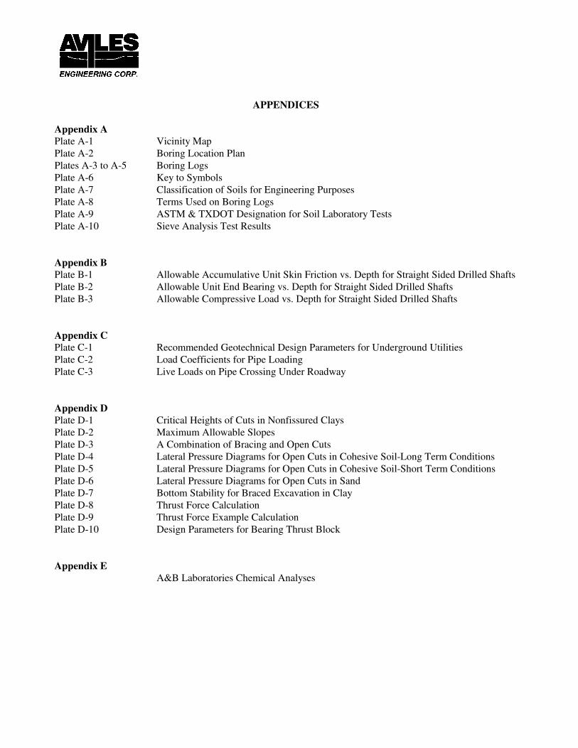
APPENDICES
Appendix A
Plate A-1 Vicinity Map
Plate A-2 Boring Location Plan
Plates A-3 to A-5 Boring Logs
Plate A-6 Key to Symbols
Plate A-7 Classification of Soils for Engineering Purposes
Plate A-8 Terms Used on Boring Logs
Plate A-9 ASTM & TXDOT Designation for Soil Laboratory Tests
Plate A-10 Sieve Analysis Test Results
Appendix B
Plate B-1 Allowable Accumulative Unit Skin Friction vs. Depth for Straight Sided Drilled Shafts
Plate B-2 Allowable Unit End Bearing vs. Depth for Straight Sided Drilled Shafts
Plate B-3 Allowable Compressive Load vs. Depth for Straight Sided Drilled Shafts
Appendix C
Plate C-1 Recommended Geotechnical Design Parameters for Underground Utilities
Plate C-2 Load Coefficients for Pipe Loading
Plate C-3 Live Loads on Pipe Crossing Under Roadway
Appendix D
Plate D-1 Critical Heights of Cuts in Nonfissured Clays
Plate D-2 Maximum Allowable Slopes
Plate D-3 A Combination of Bracing and Open Cuts
Plate D-4 Lateral Pressure Diagrams for Open Cuts in Cohesive Soil-Long Term Conditions
Plate D-5 Lateral Pressure Diagrams for Open Cuts in Cohesive Soil-Short Term Conditions
Plate D-6 Lateral Pressure Diagrams for Open Cuts in Sand
Plate D-7 Bottom Stability for Braced Excavation in Clay
Plate D-8 Thrust Force Calculation
Plate D-9 Thrust Force Example Calculation
Plate D-10 Design Parameters for Bearing Thrust Block
Appendix E
A&B Laboratories Chemical Analyses

1
GEOTECHNICAL INVESTIGATION
CITY OF COLLEGE STATION
SANDY POINT PUMP STATION IMPROVEMENTS
7290 SANDY POINT ROAD
BRYAN, TEXAS
1.0 INTRODUCTION
1.1 Project Description
Aviles Engineering Corporation (AEC) performed a geotechnical investigation for the City of College Station’s
proposed Sandy Point Pump Station Improvements, located at 7290 Sandy Point Road in Bryan, Texas. A
vicinity map is presented on Plate A-1, in Appendix A. Based on information provided by Malcolm
Pirnie/Arcadis, AEC understands that the improvements include: (i) a 20-foot high, 85 foot long by 35 foot wide
cooling tower; (ii) two 9 foot diameter by 10.5 foot high sodium hypochlorite bulk storage tanks within a metal
building canopy structure; (iii) an 8 foot long by 8 foot wide precast concrete building adjacent to the bulk storage
tanks; (iv) an asphalt pavement driveway; and (v) 14- to 48 inch diameter waterlines at the cooling tower. The
waterlines will have a maximum invert depth of approximately 10 feet and will be installed by open cut method.
1.2 Authorization
The investigation was authorized via Subcontract Agreement between AEC and Arcadis on March 26, 2013, by
Mr. Jonathan Howard, Principal of Arcadis, based upon AEC Proposal No. G2013-01-03, dated January 11,
2013.
1.3 Purpose and Scope
The purpose of this geotechnical investigation is to evaluate the subsurface soil conditions at the project site and
develop geotechnical engineering recommendations for design and construction of the proposed cooling tower,
bulk storage tank, precast concrete building, underground utilities, and asphalt driveway. The scope of this
geotechnical investigation is summarized as below:

2
1. Soil drilling and sampling of three geotechnical borings to 50 feet deep;
2. Soil laboratory testing on selected soil samples;
3. Engineering analyses and recommendations for foundation type(s) and depth, allowable bearing capacity for
mat foundation, axial capacity for drilled shafts, and subgrade preparation for the cooling tower;
4. Engineering analyses and recommendations for foundation type and depth, allowable bearing capacity, floor
slab, and subgrade preparation for the bulk tanks, canopy structure, and precast concrete building;
5. Engineering analyses and recommendations for installation of underground utilities by open cut method,
including trench shoring, bottom stability, bedding, and backfill
6. Engineering analyses and recommendations for the asphalt driveway, including pavement thickness design
and subgrade preparation;
7. Recommendations for construction of the foundations, utilities, and pavement.
2.0 SUBSURFACE EXPLORATION
Subsurface conditions at the site were investigated by drilling three soil borings to 50 feet below grade; Borings
B-1 and B-2 were performed within the cooling tower footprint and Boring B-3 was performed within the bulk
storage tank footprint. The total drilling footage was 150 feet. Boring locations were selected by AEC and
confirmed by Malcolm Pirnie in the field prior to arrival of the drill rig. Boring survey data was not available at
the time this report was prepared. The approximate boring locations are shown on the attached Boring Location
Plan on Plate A-2, in Appendix A.
The field drilling was performed with a truck-mounted drilling rig initially using dry auger method, then using
wet rotary method once groundwater and granular soils were encountered. Undisturbed samples of cohesive soils
were obtained from the borings by pushing 3-inch diameter thin-wall, seamless steel Shelby tube samplers in
accordance with ASTM D 1587. Granular soils were sampled with a 2-inch split-barrel sampler in accordance
with ASTM D 1586. Standard Penetration Test resistance (N) values were recorded for the granular soils as
“Blows per Foot” and are shown on the boring logs. Strength of the cohesive soils was estimated in the field using
a hand penetrometer. The undisturbed samples of cohesive soils were extruded mechanically from the core
barrels in the field and wrapped in aluminum foil; all samples were sealed in plastic bags to reduce moisture loss
and disturbance. The samples were then placed in core boxes and transported to the AEC laboratory for testing
and further study. The bore holes were left open for 24 hours so that additional groundwater readings could be
obtained. After the 24 hour readings were obtained, the borings were backfilled with bentonite chips. Details of
the soils encountered in the borings are presented on Plates A-3 through A-5, in Appendix A.

3
3.0 LABORATORY TESTING
3.1 Geotechnical Laboratory Testing
Soil laboratory testing was performed by AEC personnel. Samples from the borings were examined and classified
in the laboratory by a technician under supervision of a geotechnical engineer. Laboratory tests were performed
on selected soil samples in order to evaluate the engineering properties of the foundation soils in accordance with
applicable ASTM Standards. Atterberg limits, moisture contents, sieve analysis, percent passing a No. 200 sieve,
and dry unit weight tests were performed on typical samples to establish the index properties and confirm field
classification of the subsurface soils. Strength properties of cohesive soils were determined by means of torvane
(TV), unconfined compression (UC), and undrained-unconsolidated (UU) triaxial tests performed on undisturbed
samples. The test results are presented on their representative boring logs. A key to the boring logs, classification
of soils for engineering purposes, terms used on boring logs, and reference ASTM Standards for laboratory testing
are presented on Plates A-6 through A-9, in Appendix A. Sieve analyses are presented on Plate A-10, in
Appendix A.
3.2 Chemical Analyses
To evaluate the potential for sulfate and chloride attack on subgrade stabilization and underground utilities, we
selected one soil sample for chemical analyses. Resistivity, Sulfate, Chloride, and pH analyses were performed by
A & B Laboratories, Inc. A summary of the analysis results are presented on Table 1 below. A copy of the reports
by A&B Laboratories is presented in Appendix E.
Table 1. Resistivity, Sulfate, Chloride, and pH Analysis Results
Sample ID Resistivity
(ohm/cm)
Sulfate
(mg/kg)
Chloride
(mg/kg) pH
Aggressive
Environment
B-2, 8’-10’ 2155 (not tested) 8010 7.64 Yes
B-3, 2’-4’ 14124 10.6 99.6 7.02 No
Whenever the pH value is 4.5 or less, the foundation design should be based on an aggressive subsurface
environment. Alternately, if the resistivity is less than 2,000 ohms/cm, the soils should be treated as aggressive.
If the soil resistivity is between 2,000 and 5,000 ohms/cm, and the chloride ion content is greater than 100 parts
per million (ppm) or the sulfate ion content is greater than 200 ppm, the foundation design should be based on an
aggressive subsurface environment. Resistivity values greater than 5,000 ohms/cm are considered non-aggressive

4
environments. Based on the above criteria, the soil sample tested from Boring B-2 at a depth of 8 to 10 feet can
be considered an aggressive environment, while the sample from Boring B-3 at a depth of 2 to 4 feet can be
considered a non-aggressive environment.
4.0 SITE CONDITIONS
Based on our site visit, the proposed improvements will be located primarily on the west side of the existing
facility. The proposed cooling towers will be located on a flat grassy area between two 1 to 2 foot high retaining
walls (from cooling towers that were previously demolished at the site), while the bulk storage tanks will be
located in a flat grassy area to the west of the existing horizontal surge tank.
4.1 Subsurface Conditions
The soil strata encountered in our borings are summarized below:
Boring Depth (ft) Description of Stratum
B-1 0 - 4 Fill: stiff to very stiff, Sandy Lean Clay (CL), with roots, sand and clay
pockets, and gravel
4 - 6 Fill: Poorly Graded Sand w/Silt (SP-SM), with gravel and clay pockets
6 - 10 Fill: Clayey Sand (SC), with lean clay pockets
10 - 14 Fill: stiff to very stiff, Sandy Lean Clay (CL), with abundant sand seams and
pockets
14 - 18 Clayey Sand (SC)
18 - 28 Medium dense to very dense, Silty Sand (SM)
28 - 43 Firm to hard, Fat Clay (CH), with slickensides
43 - 50 Very dense, Silty Sand (SM)
B-2 0 - 2 Fill: hard, Sandy Lean Clay (CL), with silt seams and gravel
2 - 4 Fill: stiff, Lean Clay (CL), with gravel
4 - 12 Fill: hard, Lean Clay (CL), with sand seams and pockets
12 - 14 Medium dense, Silty Sand (SM), with clay pockets
14 - 16 Medium dense, Clayey Sand (SC), with fat clay pockets
16 - 18 Medium dense, Poorly Graded Sand w/Clay (SP-SC)
18 - 22 Stiff to very stiff, Sandy Lean Clay (CL), with silty sand seams
22 - 28 Very dense, Silty Sand (SM), with clayey sand pockets
28 - 43 Very stiff to hard, Fat Clay (CH), with silt layers
43 - 50 Very dense, Clayey Sand (SC), with fat clay pockets
B-3 0 - 10 Hard, Sandy Fat Clay (CH)
10 - 22 Medium dense, Clayey Sand (SC)
22 - 32 Medium dense to dense, Silty Sand (SM)
32 - 45.5 Stiff to hard, Fat Clay (CH), with silt partings
45.5 - 50 Hard, Lean Clay (CL), with abundant silt seams

5
The cohesive soils in the borings have Liquid Limits (LL) that varied from 24 to 80 and Plasticity Indices (PI) that
varied from 11 to 47. This indicates that the cohesive soils at the site have low to very high plasticity. The
cohesive soils encountered are classified as “CL” and “CH” type soils and the granular soils encountered are
classified as “SM”, “SC”, “SP-SM”, and “SP-SC” type soils in accordance with the Unified Soil Classification
System (USCS). “CH” soils undergo significant volume changes due to seasonal changes in soil moisture
contents. “CL” type soils with lower LL (less than 40) and PI (less than 20) generally do not undergo significant
volume changes with changes in moisture content. However, “CL” soils with LL approaching 50 and PI greater
than 20 essentially behave as “CH” soils and could undergo significant volume changes.
Groundwater was encountered in the borings at a depth of 18 to 29 feet below grade during drilling and was
subsequently observed at a depth of 14.1 to 23.8 feet approximately 15 minutes after the initial encounter,
indicating that the groundwater at the site could be pressurized. The groundwater levels varied from 11 to 25.1
feet below grade approximately 24 hours after completion of drilling. A summary of groundwater readings is
presented in Table 2.
Table 2. Groundwater Depths below Existing Ground Surface
Boring
No.
Boring
Depth
(ft)
Groundwater Depth
Encountered during
Drilling (ft)
Groundwater Depth
15 min. after Initial
Encounter (ft)
Groundwater
Depth After 24
Hours (ft)
B-1 50 18 n/a 13.1
B-2 50 18 14.1 11.0
B-3 50 29 23.8 25.1
The information in this report summarizes conditions found on the date the borings were drilled. It should be
noted that our groundwater observations are short-term; groundwater depths and subsurface soil moisture
contents will vary with environmental variations such as frequency and magnitude of rainfall and the time of year
when construction is in progress.
4.2 Subsurface Variations
It should be emphasized that: (i) at any given time, ground water depths can vary from location to location, and (ii)
at any given location, ground water depths can change with time. Ground water depths will vary with seasonal
rainfall and other climatic/environmental events. Subsurface conditions may vary away from and between the
boring locations.

6
Clay soils in the Brazos Valley area typically have secondary features such as slickensides and contain sand/silt
seams/lenses/layers/pockets. It should be noted that the information in the boring logs is based on 3-inch diameter
soil samples which were generally obtained at intervals of 2 feet in the top 20 feet of the borings and at intervals
of 5 feet thereafter to the boring termination depths. A detailed description of the soil secondary features may not
have been obtained due to the small sample size and sampling interval between the samples. Therefore, while
some of AEC’s logs show the soil secondary features, it should not be assumed that the features are absent where
not indicated on the logs.
5.0 ENGINEERING ANALYSIS AND RECOMMENDATIONS
Based on information provided by Malcolm Pirnie/Arcadis, AEC understands that the improvements include: (i)
a 20-foot high, 85 foot long by 35 foot wide cooling tower; (ii) two 9 foot diameter by 10.5 foot high sodium
hypochlorite bulk storage tanks within a 32 feet long by 18 feet wide metal building canopy structure; (iii) an 8
foot long by 8 foot wide precast concrete building adjacent to the bulk storage tanks; (iv) an asphalt pavement
driveway; and (v) 14- to 48 inch diameter waterlines at the cooling tower. The waterlines will have a maximum
invert depth of approximately 10 feet and will be installed by open cut method.
5.1 Abandonment of Existing Wet Well
According to Malcolm Pirnie, there is an existing abandoned 17 foot deep wet well located to the east of the
proposed cooling tower location; however details regarding existing cooling tower foundation demolition or how
the wet well was abandoned (whether it was backfilled or not) were not available. In addition, the location and
dimensions of the wet well were not available at the time this report was prepared. AEC should be notified if
existing abandoned underground utilities or the wet well are located within (or immediately adjacent to) the
footprint of the proposed cooling tower so that our recommendations can be revised as necessary.
Abandonment of Underground Utilities: Existing drainage pipelines that are to be abandoned and are located
beneath or behind the existing wet well should be fully drained or pumped and backfilled with flowable fill (lean
concrete). Flowable fill should be in accordance with Item 401 of the 2004 Texas Department of Transportation
(TxDOT) Standard Specifications for Construction and Maintenance of Highways, Streets, and Bridges, or
equivalent local standards.

7
Partial Breaking of Wet Well Slab: At least twenty-four hours after the drainage pipelines have been backfilled
with flowable fill, the middle portion of the bottom slab should be cut with 2 to 3 inch diameter holes with a 5 foot
center-to-center spacing. A minimum 3 or 4 foot distance should be maintained from the core holes to the walls
of the wet well.
Saw Cut Top of Walls of the Wet Well: To avoid “hard spots” beneath future pavement and/or finished ground
surface, the top 12- to 24-inches of the wet well walls below the existing ground surface should be removed by
saw cutting.
Backfill of Wet Well: We recommend that a minimum 6 inch thick compacted bank sand blanket be placed on top
of the wet well slab. Bank sand should meet the requirements of ASTM C33 concrete sand. The concrete sand
should be placed in maximum 8 inch thick loose lifts and compacted to a minimum of 95 percent of its ASTM
D 698 maximum dry density at a moisture content within 2 percent of optimum. Above the compacted sand
blanket layer, compacted select fill should be used to backfill the wet well to the existing ground surface. The
select fill should be placed in maximum 8 inch thick loose lifts and compacted to a minimum of 95 percent of its
ASTM D 698 maximum dry density at a moisture content between optimum and 3 percent above optimum. Fill
within 3 feet of walls should be placed in loose lifts no more than 4 inches thick and compacted using hand
tampers, or small self-propelled compactors. Select fill requirements are presented in Section 5.7.1 of this report.
5.2 Cooling Tower
According to Malcolm Pirnie, the cooling tower will have a footprint that is approximately 85 feet long by 35 feet
wide. The cooling tower will be supported on concrete plinths within a 2 foot deep concrete basin; the bottom of
the basin slab will be approximately 6 to 12 inches below grade. The combined weight of the cooling tower and
water within the concrete basin will be approximately 500,000 pounds.
Based on Borings B-1 and B-2, the soil conditions at the cooling tower generally consist of approximately 12 to
14 feet of stiff to hard sandy lean clay (CL) and clayey/poorly graded sand (SC/SP-SM) fill at the ground surface,
underlain by approximately 14 to 16 feet of medium dense to very dense silty/clayey sand (SM/SC/SP-SC) and
stiff to very stiff sandy lean clay (CL), followed by approximately 15 feet of firm to hard fat clay (CH), then
approximately 7 feet of very dense clayey sand (SC) to the boring termination depths of 50 feet below grade. AEC
notes that the 12 to 14 feet of fill encountered in Borings B-1 and B-2 are not uniform. It is AEC’s opinion that

8
spread footings should not be used due to the concern of potential differential settlement. AEC recommends that
the cooling tower be supported on either a mat foundation or straight-sided drilled shafts.
5.2.1 Option 1 - Mat Foundation
Based on Borings B-1 and B-2, the top 12 to 14 feet of fill at the site consists of stiff to hard sandy lean clay and
medium dense clayey/poorly graded sand (SC/SP-SM). To reduce the potential of soil movement due to
differential settlement and provide competent and uniform soil support for the mat foundation, we recommend
that the mat foundation be founded at least 5 feet below existing grade. This option assumes that the structural
continuity and flexural strength of the mat foundation can bridge over non-uniform soils underneath, resulting in
smaller differential settlements than spread footings.
Mat Foundation: A mat foundation founded at 5 feet below existing grade can be designed for a net allowable
bearing capacity of 2,000 pounds per square foot (psf) for sustained loads and 3,000 psf for total loads, based on
a minimum factor of safety (FS) of 3 for sustained loads and 2 for total loads; whichever is critical should be used.
Modulus of Subgrade Reaction: The modulus of subgrade reaction (k) is frequently used in the structural analysis
of mat foundations. Based on the soil conditions encountered and the size of the mat foundation, we recommend
using k = 60 pounds per cubic inch (pci) for a mat foundation founded at a depth of 5 feet below the existing
ground surface.
Mat Settlement: A detailed settlement analysis for a mat foundation is beyond the scope of this investigation.
Based on the soil conditions encountered, we estimate that a mat foundation designed and constructed as
recommended will experience total settlements within 1 inch.
5.2.2 Option 2 - Straight Sided Drilled Shafts
Straight-sided drilled shafts can be used as an alternative to a mat foundation. We performed drilled shaft
analyses using O’Neill and Reese’s method, “Drilled Shaft Design and Construction” (1999). In the analyses, we
neglected skin friction from a zone of 5 feet below the ground surface to account for potential construction
disturbance and potential shrinkage of the surficial expansive clay fill soils. We used a FS of 2 and 3 for skin
friction and end bearing, respectively.
9
The total allowable compressive axial bearing capacity of a straight-sided drilled shaft is the sum of the allowable
skin friction (obtained by multiplying the shaft perimeter by the allowable unit cumulative skin friction beginning
from 5 feet below existing grade to the design depth) and the allowable end bearing (obtained by multiplying the
drilled shaft cross-sectional area by the allowable unit end bearing at the design depth). The allowable
accumulative unit skin friction capacity vs. depth curve, allowable unit end bearing vs. depth curve, and allowable
compressive load vs. depth curve for 24-, 36-, and 48-inch diameter straight-sided drilled shafts are presented on
Plates B-1 through B-3, in Appendix B.
When a shaft tip is terminated in a strong layer underlain by a weak layer and the thickness between the shaft tip
and the top of the weak layer is less than 2 shaft diameters (feet), we recommend the use of the design end bearing
of the lower weak layer.
Drilled Shaft Spacing: To reduce the influence of adjacent drilled shafts and group effects, the minimum
center-to-center spacing between adjacent shafts should be at least 3 times the diameter of the larger shafts; the
minimum edge-to-edge spacing between adjacent shafts should not be less than 3 feet. For a drilled shaft group
with a pier cap in contact with the ground, the individual capacity of the drilled shaft should be multiplied by an
efficiency factor, η, where η = 0.75 for a center-to-center spacing of 3D (D is the diameter of the larger shaft) and
η = 1.0 for a center-to-center spacing of 6D. The value of η may be linearly interpolated for intermediate spacing.
The group capacity will be the smaller of: (i) the sum of the individual capacities of the drilled shaft multiplied by
η, or (ii) the bearing capacity for the block (i.e., the group of the drilled shafts and their enclosed soil mass acting
as a block foundation) failure. The minimum spacing must include proper allowances for cantilever tolerance of
alignment and possible oversizing of the drilled hole.
Drilled Shaft Settlements: A detailed settlement analysis for drilled shafts is beyond the scope of this
investigation. Based on the soil conditions encountered, we estimate that straight sided drilled shafts designed and
constructed as recommended will experience total settlements within 1 inch.
Drilled Shaft Construction: Drilled shaft foundations should be constructed in accordance with Item 416 of the
2004 TxDOT Standard Specifications, or equivalent local standards. Based on Borings B-1 and B-2, drilled shaft
excavations will encounter saturated granular soils from a depth of 12 to 14 feet below grade and groundwater at
14 to 18 feet below grade, which could cause sidewall sloughing or collapse during shaft excavation. To maintain
integrity of the shaft excavations, we recommend the use of temporary steel casing or bentonite slurry for drilled
shaft construction. AEC does not recommend the use of polymer slurry for shaft construction.

10
For slurry method, the bentonite slurry should be used prior to encountering ground water or granular soils and the
slurry head should be maintained at least 5 feet higher than the ground water at the site during construction. The
concrete should be placed using a tremie to displace the lower density slurry. Care must be taken to ensure that
tremie is positioned and maintained at the bottom of excavation until a height of 5 feet of concrete has been poured.
As more concrete is added, the tremie should be maintained at a minimum distance of 5 feet below the top of the
concrete pour.
New drilled shafts should not be excavated within 3 shaft diameters (edge to edge) of an open shaft excavation,
or one in which concrete has been placed in the preceding 24 hours, to prevent movement of fresh concrete from
the recently filled footing to an adjacent unfilled footing. Placement of concrete should be accomplished as soon
as possible after excavation to reduce changes in the state of stress and possible sloughing in the foundation soils.
No shafts should be left open overnight or poured without the prior approval of the Owner’s Representative.
In addition, each footing excavation should be inspected by a qualified Owner’s Representative prior to placing
concrete, to check that: (1) the footing excavation has been constructed to the specified dimensions at the
recommended depth and formation; and (2) excessive amounts of soil cuttings and any soft-compressible
materials have been removed from the bottom of the excavation.
5.2.3 Concrete Basin
Subgrade Preparation: Subgrade preparation should extend a minimum of 5 feet beyond the cooling tower basin
perimeter. A minimum of 6 inches of surface soils, existing vegetation, trees, roots, and other deleterious
materials should be removed and wasted. The excavation depth should be increased when inspection indicates the
presence of organics and deleterious materials to greater depths.
After surface stripping, existing overburden soils should be excavated to achieve either: (i) the bottom of the mat
foundation elevation at 5 feet below grade; or (ii) if drilled shafts are used to support the cooling tower, the bottom
of the basin slab elevation at approximately 6 to 12 inches below grade. The exposed subgrade should be
proof-rolled in accordance with Item 216 of the 2004 TxDOT Standard Specifications to identify and remove any
weak, compressible, or other unsuitable materials; such materials should be replaced with compacted select fill or
clean stabilized soils.
11
Grade Beams: We recommend that foundation grade beams (if drilled shafts are used) be founded at least 30
inches below the lowest final grade. The grade beams can be constructed on 6 inch carton forms. If carton forms
are used, care should be taken so that the carton forms do not collapse during concrete placement and will not be
exposed to water in the grade beam excavations. Surface water should not be allowed to seep into and remain in
the carton form space during the life of the structures. If no carton forms will be used, we recommend that tensile
reinforcement be placed in both top and bottom of the beams. The drilled shafts and beams should be tied
together.
Moisture Barrier: We recommend that a horizontal moisture barrier (minimum 10-mil thick) be placed below the
concrete slab to move edge effects away from the slab and mitigate seasonal fluctuations of water content directly
below the structure.
Lateral Earth Pressures: The magnitudes of the lateral earth pressures on the basin walls will depend on the type
and density of the backfill, surcharge on the backfill, and hydrostatic pressure, if any. If the backfill is
over-compacted or if highly plastic clays are placed behind the walls, the lateral earth pressure could exceed the
vertical pressure.
Lateral pressure resulting from construction equipment, structural loads, or other surcharge on the top of the basin
walls should be taken into account by adding the equivalent uniformly distributed surcharge to the design lateral
pressure. Hydrostatic pressure should also be included in the design (while assuming the basin is drained). We
recommend that at least 240 psf uniform surcharge pressure be considered for design of the walls.
AEC assumes that the basin walls will be cast-in-place reinforced concrete and that no lateral movement is
allowed. As a result, the basin walls which can be designed based on at-rest earth pressure. The at-rest earth
pressure at depth z can be determined by Equation (1). The walls should consider short term and long term
conditions, whichever condition is critical should be used for design. Design soil parameters for retaining wall
design are presented on Plate C-1, in Appendix C.
p0 = (qs+γ h1+γ’ h2)K0 + γwh2 ............ Equation (1)
where, p0 = at-rest earth pressure, psf.
qs = uniform surcharge pressure, minimum 240 psf.
γ, γ’ = wet and buoyant unit weights of soil, pcf.
h1 = depth from ground surface to groundwater table, feet.
h2 = z-h1, depth from groundwater table to point under consideration, feet.
Z = depth below ground surface, feet.

12
K0 = coefficient of at-rest earth pressure.
γw = unit weight of water, 62.4 pcf.
Basin Wall Backfill: If the basin excavation will be laid/stepped back, we recommend use of select fill as backfill
behind the basin walls. The excavation area should extend a minimum of 2 feet horizontally beyond the basin
perimeter, then slope upwards at a H:V = 1:1 slope or flatter. Select fill criteria are presented in Section 5.7.1 of
this report.
5.3 Sodium Hypochlorite Bulk Storage Tanks
Based on the drawings provided by Malcolm Pirnie, the two 9 foot diameter bulk storage tanks will be located
within a 32 foot long by 18 feet wide concrete basin, covered by a metal building canopy. Each bulk storage tank
will have an operating weight of approximately 60,000 pounds. Based on Boring B-3, the subsurface conditions
at the storage tanks generally consists of approximately 10 feet of hard fat clay (CH), underlain by approximately
22 feet of clayey/silty sand (SC/SM), followed by approximately 13.5 feet of stiff to hard fat clay (CH), then
approximately 4.5 feet of hard lean clay (CL) with silt to the boring termination depth of 50 feet below grade.
Based on Boring B-3, the surface soils within the structure footprint generally consist of highly expansive clay to
a depth of 10 feet. AEC recommends that the bulk storage tanks and canopy building be supported on
drilled-and-underreamed footings, founded on top of the medium dense clayey sand (SC) stratum at a depth of 10
feet below grade.
5.3.1 Drilled-and-Underreamed Footings
Allowable Bearing Capacity: AEC recommends that drilled-and-underreamed footings be founded at a depth of
10 feet below existing grade, and be designed for a net allowable bearing capacity of 3,500 psf for sustained loads
and 5,250 psf for total loads, based on a minimum FS of 3 for sustained loads and 2 for total loads, whichever is
critical should be used.
Uplift Capacity: According to O’Neill and Reese (1999), the uplift resistance of a drilled-and-underreamed
footing in cohesive soils can be calculated as:
Q (uplift) = (su Nu Au)/FS1 + Wc/FS2 + Ws/FS3 ............ Equation (2)
Nu = 1.5 Db / Bb ≤ 9 ............ Equation (3)
13
where: Q = Allowable uplift resistance of a drilled footing, lbs
su = Average undrained shear strength of the cohesive soil between the base of the bell and
2 Bb above the base; use su = 2,000 psf for this structure (based on Boring B-3)
Nu = Bearing capacity factor for base uplift resistance, Nu ≤ 9
Db = Depth of base below ground surface minus the seasonal moisture change zone for a
drilled and underreamed footing, ft; the seasonal moisture change zone in
Bryan/College Station can be considered as 15 feet below the existing ground surface
Bb = Diameter of the bell, ft
Bs = Diameter of the shaft, ft
Wc = Effective weight of concrete footing, lbs
Ws = Effective weight of projected soil above the bell, lbs (use unit weight, γ = 125 pcf for
soils above water table, and buoyant unit weight γ’ = 65 pcf for soils below water table)
Au = π/4 (Bb2 - Bs
2), projected area of bell over shaft, ft
2
FS1, FS2, FS3 = Factors of Safety for uplift resistance
We recommend that the following safety factors be used for uplift design: FS of 2 for soil cohesion (FS1 = 2), FS
of 1.1 for dead weight of footing (FS2 = 1.1), and FS of 1.5 for weight of soil above the bell (FS3= 1.5). Based
on above equations, the uplift resistance of a drilled-and-underreamed footing can be increased by extending the
founding depth of the footing or increasing the diameter of the bell.
Vertical Reinforcement: To withstand uplift forces resulting from the shrink/swell movements of clay soils in the
moisture active zone, each footing should contain reinforcing steel throughout its full length to sustain an uplift
load of at least 38d kips, where “d” is the diameter of the shaft in feet.
Footing Spacing: To reduce stress overlap from adjacent footings and potential construction problems, the
minimum edge-to-edge clear spacing between the underreams should not be less than 0.6 x diameter of the larger
underream. New foundations for the building should be spaced to reduce the potential of new foundations
affecting existing building foundations (and vice versa) by placing the new foundations outside the bearing (stress)
zone of existing foundations. The bearing (stress) zone can be defined by a line drawn downward from the outer
edge of the existing foundation and inclined at an angle of 45 degrees to the vertical.
Footing Settlements: A detailed settlement analysis for drilled-and-underreamed footings is beyond the scope of
this investigation. Based on the soil conditions encountered and the anticipated structural loads, we estimate that
drilled-and-underreamed footings, designed and constructed as recommended in this report, will experience total
settlements on the order of 1 inch.

14
Drilled-and-Underreamed Footing Construction: Drilled-and-underreamed footings should be constructed in
accordance with Item 416 of the 2004 TxDOT Standard Specifications, or equivalent local standards. A qualified
geotechnical technician should check each footing excavation prior to placing concrete to insure that:
1) The footing has been constructed to the specified dimensions at the recommended depth and founded in
the correct formation as indicated in this report;
2) The column is concentric with the pier cap/grade beam and drilled footing; and
3) Excessive cuttings, any soft or compressible materials, and ponded water are removed from the bottom
of the excavation.
There is a possibility that slickensides and/or pockets/seams of sands/silts within the clay soils may make
underreaming (belling) difficult, and result in potential sloughing or caving-in of the shaft excavation sidewalls
during construction, particularly for underreams over 6 feet in diameter. We recommend that a maximum
diameter ratio of bell to shaft not exceed 2 to 1. Based on Boring B-3, ground water will probably not be
encountered within the drilled shaft excavations; however, the site groundwater level will fluctuate with seasonal
rainfall and other climatic events, and may be higher at the time of construction. If ground water is encountered
within the cohesive soils during construction, sump pumps may be used to pump water out from the excavations
and soft sediments should be removed. However, if significant sloughing or caving occurs during
drilled-and-underreamed shaft excavation, further footing excavation should be stopped and a reduced bell/shaft
ratio or even straight-sided shafts (matching the bell diameter) with bentonite slurry or temporary casing may be
necessary.
Placement of concrete should be accomplished immediately after excavation is completed to reduce potential for
sloughing of the foundation soils. Footing excavations should not be left open overnight. No concrete should be
placed without the prior approval of the Owner’s Representative. New drilled footings should not be excavated
within 2 bell diameters (edge to edge) of an open footing excavation, or one in which concrete has been placed in
the preceding 24 hours, to prevent movement of fresh concrete from the recently filled footing to an adjacent
unfilled footing.
5.3.2 Floor Slab
Estimated Soil Movements: Expansive clays exhibit a potential to shrink and swell with changes in their moisture
contents. The changes in the soil moisture content are usually caused by variations in the seasonal amount of
rainfall and evaporation rates or other localized factors like the moisture withdrawal by nearby trees. The seasonal

15
moisture active zone generally extends to about 15 feet below ground in the Brazos Valley area, and will be deeper
if trees with deep root zones exist adjacent to the structures.
Potential Vertical Rise (PVR) is an estimate of the potential of an expansive soil to swell from its current state.
For the top 15 feet of the existing soils encountered in Boring B-3, the total PVR for the tanks/canopy building is
estimated to be about 3.8 inches based on in-situ moisture conditions. PVR was computed using TxDOT test
method Tex-124-E.
Additional movements can occur in areas if water is allowed to pond during or after construction on soils with
high plasticity, or if highly plastic soils are allowed to dry out prior to fill or concrete placement. High plasticity
clay may also experience shrinkage during periods of dry weather as moisture evaporation occurs at the ground
surface and the groundwater table drops. The actual PVR of the site will be highly dependent upon the actual PI
and moisture regime of the clayey soils at the time of construction. Therefore, uniformity and preservation of the
moisture contents of the near surface clays during construction and during the life of the structure is critical to
reducing potential shrink-swell movement of the floor slab.
Table 3. Estimated PVR vs. Thickness of Replacement Fill (Based on Boring B-3)
Thickness of Replacement Fill Beneath
the Existing Ground Surface (ft) PVR (in)
0 3.8
1 3.3
2 2.8
3 2.2
4 1.5
5 1.1
6 0.6
Floor Slab: In general, the tolerable differential vertical movement for a common building slab is about 1 inch.
To limit the PVR to 1 inch, the following approaches can be used: (1) a drilled-footing supported structural floor
slab in combination with 8 inch carton forms between the bottom of the slab and the subgrade soil; or (2)
excavating approximately 6 feet of existing soils and replacing them with a low-expansive select fill material (in
accordance with Table 3).

16
5.3.2.1 Option 1 - Structural Floor Slab
The most effective method to mitigate movement of subgrade soils due to shrink-swell cycles of expansive soils
is construction of a drilled-footing supported structural floor slab with 8 inch carton forms between the bottom of
the slab and the top of the subgrade soil.
Subgrade Preparation: Subgrade preparation should extend a minimum of 5 feet beyond the floor slab perimeter.
Thereafter, a minimum of 6 inches of surface soils, existing vegetation, trees, roots, and other deleterious
materials shall be removed and wasted. The excavation depth should be increased when inspection indicates the
presence of organics or deleterious materials to greater depths.
The exposed subgrade should then be proof-rolled in accordance with Item 216 of the 2004 TxDOT Standard
Specifications, to identify and remove any weak, compressible, or other unsuitable materials; such materials
should be replaced with clean onsite clay soils. Afterwards, general fill can be placed and compacted to achieve
the design finished floor elevation (FFE) of the building (i.e. the bottom of the carton forms). General fill
recommendations are presented in Section 5.7.2 of this report.
Grade Beams: We recommend that foundation grade beams be founded at least 30 inches below the lowest final
grade. The grade beams should be constructed on 8 inch carton forms. Care should be taken so that the carton
forms do not collapse during concrete placement and will not be exposed to water in the grade beam excavations.
Surface water should not be allowed to seep into and remain in the carton form space during the life of the
structures. The drilled shafts and beams should be tied together.
Moisture Barrier: To prevent mildew or mold growth on the underside of the structural floor slab, we recommend
that a horizontal moisture barrier (minimum 10-mil thick) be placed below the concrete slab (on top of the carton
forms).
5.3.2.2 Option 2 - Subgrade Supported Floor Slab
A less expensive alternative to a structural slab is a reinforced on-grade floor slab. A concrete slab-on-grade in
conjunction with limited fill replacement can be considered, if the Owner is willing to take some risk of floor slab
movement. This option assumes that uniformity and preservation of the moisture contents of the near surface clays
during construction and during the life of the structure are maintained adequately, and that any resultant

17
movements can be adequately sustained by the subgrade soils and foundation system.
Subgrade Preparation: Subgrade preparation should extend a minimum of 5 feet beyond the floor slab perimeter.
A minimum of 6 inches of surface soils, existing vegetation, trees, roots, and other deleterious materials shall be
removed and wasted. The excavation depth should be increased when inspection indicates the presence of
organics and deleterious materials to greater depths.
Afterwards, an additional 3.5 feet (total depth of 4 feet, which includes the 6 inches of surface removal) of existing
soils should be removed. The exposed subgrade should be proof-rolled in accordance with Item 216 of the 2004
TxDOT Standard Specifications to identify and remove any weak, compressible, or other unsuitable materials;
such materials should be replaced with compacted select fill or clean stabilized soils.
After proof-rolling, we recommend that the top 6 inches of exposed subgrade be stabilized with a minimum of 7
percent hydrated lime (by dry soil weight). The actual percentage of lime should be determined by lime-series or
pH method in a laboratory prior to construction. After subgrade stabilization, compacted select fill or clean,
stabilized soils should then be used to achieve the design FFE of the building. Select fill or stabilized soil should
be in accordance with Section 5.7.1 of this report.
According to Table 3 in Section 5.3.2 of this report, the PVR for 4 feet of soil replacement and 6 inches of
subgrade stabilization is 1.3 inches, which is still greater than 1 inch; the Owner should be aware that some risk
of floor slab movement is still present if this floor slab option is selected. If conditions which exacerbate moisture
variations such as the presence of trees, poor drainage, excessive drying, or wetting of subsurface soils, or leaking
underground utilities are located nearby, the floor slab total vertical movements and net differential vertical
movements could be higher than estimated.
Grade Beams: We recommend that foundation grade beams be founded at least 30 inches below the lowest final
grade. The grade beams can be constructed on 8 inch carton forms. If carton forms are used, care should be taken
so that the carton forms do not collapse during concrete placement and will not be exposed to water in the grade
beam excavations. Surface water should not be allowed to seep into and remain in the carton form space during
the life of the structures. If no carton forms will be used, we recommend that tensile reinforcement be placed in
both top and bottom of the beams. The foundations and beams should be tied together.

18
Floor slabs are typically structurally tied to the grade beams. Alternatively, isolating the floor slabs from grade
beams with a flexible impervious compound will be beneficial to reduce the potential for slab cracking due to
differential soil movement; however, its use will not mitigate the total and differential PVR movements and the
floor slabs are expected to move corresponding to the subgrade soils.
Moisture Barrier: We recommend that a horizontal moisture barrier (minimum 10-mil thick) be placed below the
concrete slab to move edge effects away from the slab and mitigate seasonal fluctuations of water content directly
below the structure.
5.4 Precast Concrete Building
Based on information provided by Malcolm Pirnie, the precast concrete control building will be located on the
north side of the proposed bulk storage tanks. The one-story precast building will have a footprint that is
approximately 8 feet long by 8 feet wide, and will weigh approximately 45,000 pounds. AEC assumes that the
FFE of the proposed building will be at or near existing grade. Based on the soil conditions encountered in Boring
B-3, AEC recommends that the precast concrete building also be supported on drilled-and-underreamed footings,
founded at 10 feet below grade.
Recommendations for the building foundations and subgrade preparation for the precast building are presented in
Section 5.3 of this report.
5.5 Installation of Underground Utilities by Open-Cut Method
Underground utilities installed by open-cut methods should be installed in accordance with Item 400 of the 2004
TxDOT Standard Specifications, or equivalent local standards. AEC understands that the proposed underground
water lines will have a maximum invert depth of 10 feet below grade and will be installed by open cut method.
5.5.1 Geotechnical Parameters for Underground Utilities
Recommended geotechnical parameters for the subsurface soils along the alignments to be used for design of
underground utilities are presented on Plate C-1, in Appendix C. The design values are based on the results of
field and laboratory test data on individual boring logs as well as our experience. It should be noted that because
of the variable nature of soil stratigraphy, soil types and properties along the alignment or at locations away from

19
a particular boring may vary substantially.
5.5.2 Loadings on Pipes
Underground utilities support the weight of the soil and water above the crown, as well as roadway traffic and any
structures that exist above the utilities.
Earth Loads: For underground utilities to be installed using open cut methods, the vertical soil load We can be
calculated as the larger of the two values from Equations (4) and (6):
We = Cd γ Bd2 ............ Equation (4)
Cd = [1- e -2Kµ’(H/Bd)
]/(2Kµ’) ............ Equation (5)
We = γBcH ............ Equation (6)
where: We = trench fill load, in pounds per linear foot (lb/ft);
Cd = trench load coefficient, see Plate C-2, in Appendix C;
γ = effective unit weight of soil over the conduit, in pounds per cubic foot (pcf);
Bd = trench width at top of the conduit < 1.5 Bc (ft);
Bc = outside diameter of the conduit (ft);
H = variable height of fill (ft);
when the height of fill above the top of the conduit Hc >2 Bd, H = Hh (height of fill above the
middle of the conduit). When Hc < 2 Bd, H varies over the height of the conduit; and
Kµ’ = 0.1650 maximum for sand and gravel,
0.1500 maximum for saturated top soil,
0.1300 maximum for ordinary clay,
0.1100 maximum for saturated clay.
When underground conduits are located below groundwater, the total vertical dead loads should include the
weight of the projected volume of water above the conduits.
Traffic Loads: The vertical stress on top of an underground conduit, pL (psf), resulting from traffic loads (from a
H-20 or HS-20 truck) can be obtained from Plate C-3, in Appendix C. The live load on top of the underground
conduit can be calculated from Equation (7):
WL = pL Bc ............ Equation (7)
where: WL = live load on the top of the conduit (lb/ft);
pL = vertical stress (on the top of the conduit) resulting from traffic loads (psf);
Bc = outside diameter of the conduit, (ft);

20
Lateral Loads: The lateral soil pressure pl can be calculated from Equation (8); hydrostatic pressure should be
added, if applicable.
pl = 0.5 (γHh + ps) ............ Equation (8)
where: Hh = height of fill above the center of the conduit (ft);
γ = effective unit weight of soil over the conduit (pcf);
ps = vertical pressure on conduit resulting from traffic and/or construction equipment (psf).
5.5.3 Deflections of Flexible Pipes
Deflection is one of the controlling factors in the design of buried flexible or semi-rigid pipes, such as PVC and
ductile iron pipes. These pipes deflect under soil and surcharge loads; the amount of deflection is a function of the
service load on the pipe, the stiffness of the pipe, and the surrounding soil.
The deflection can be calculated using the Modified Iowa Formula, expressed as Equation (9), and the effective
stiffness, E/ of the surrounding soil. The E
/ is a combination of the stiffness of the pipe bedding material, E’B and
the stiffness of the native soil, E’N. Long-term deflection values are typically used for flexible/semi-rigid pipe
design; these values may be obtained by applying an appropriate deflection lag factor, DL, to the short-term
deflection values used in the Modified Iowa Formula.
'061.03
ER
EI
KWDx L
+
=∆ ............ Equation (9)
where: x∆ = pipe deflection (in);
DL = deflection lag factor,
(a) use minimum 1.0 for granular backfill and the full prism load is assumed to act on the
pipe, (b) use minimum 1.5 for granular backfill and assumed trench loadings, (c) use
minimum 2.5 for sandy lean clay (CL) where the backfill can become saturated
K = bedding constant, typically 0.11,
W = [We (from Eq. 6) + WL (from Eq. 7) +Ww], total service load on the crown of the pipe, (lb/in);
Ww = weight of water prism (if any) above the crown of the pipe
E = initial modulus (Young’s modulus) of the pipe material (psi);
I = pipe wall moment of inertia (in.4/in);
R = mean pipe radius (in);
E/ = effective modulus of soil reaction (psi)
The effective modulus of soil reaction, E/, may be obtained from the equations presented below:
E/ = zeta * E’B ............ Equation (10)

21
zeta = '/'*)44.1(
44.1
NB EEff −+ ............. Equation (11)
where: f = )1/(444.0154.1
1/
−+
−
cd
cd
BB
BB ............ Equation (12)
and: Bd = trench width at the top of the pipe (ft);
Bc = outside diameter of the pipe (ft).
For the stiffness of the pipe bedding material E’B, 2,000 psi can be used for granular materials such as clayey sand,
silty sand, silty gravel or clayey gravel (containing less than 12% fines) with a minimum 95 percent ASTM D-698
(Standard Proctor) compaction. Effective Modulus of Soil Reaction for natural soil, E’N is presented on Plate C-1,
in Appendix C.
5.5.4 Trench Stability
Cohesive soils in the Brazos Valley area contain many secondary features which affect trench stability, including
sand seams and slickensides. Slickensides are shiny weak failure planes which are commonly present in fat clays;
such clays often fail along these weak planes when they are not laterally supported, such as in an open excavation.
The Contractor should not assume that slickensides and sand seams/layers/pockets are absent where not indicated
on the logs.
The Contractor should be responsible for designing, constructing and maintaining safe excavations. Care should
be taken so that the excavations do not cause any distress to existing structures.
Trenches 20 feet and Deeper: OSHA requires that shoring or bracing for trenches 20 feet and deeper be
specifically designed by a licensed professional engineer.
Trenches Less than 20 Feet Deep: Trench excavations that are less than 20 feet deep may be shored, sheeted and
braced, or laid back to a stable slope for the safety of workers, the general public, and adjacent structures, except
for excavations which are less than 5 feet deep and verified by a competent person to have no cave-in potential.
The excavation and trenching should be in accordance with Occupational Safety and Health Administration
(OSHA), Safety and Health Regulations, 29 CFR, Part 1926. Recommended OSHA soil types for trench design
for existing soils can be found on Plate C-1, in Appendix C. Fill soils are considered OSHA Class ‘C’; submerged
cohesive soils should also be considered OSHA Class ‘C’, unless they are dewatered first.
22
Critical Height is defined as the height a slope will stand unsupported for a short time; in cohesive soils, it is used
to estimate the maximum depth of open-cuts at given side slopes. Critical Height may be calculated based on the
soil cohesion. Values for various slopes and cohesion are shown on Plate D-1, in Appendix D. Cautions listed
below should be exercised in use of Critical Height applications:
1. No more than 50 percent of the Critical Height computed should be used for vertical slopes. Unsupported
vertical slopes are not recommended where granular soils or soils that will slough when not laterally
supported are encountered within the excavation depth.
2. If the soil at the surface is dry to the point where tension cracks occur, any water in the crack will increase
the lateral pressure considerably. In addition, if tension cracks occur, no cohesion should be assumed for
the soils within the depth of the crack. The depth of the first waler should not exceed the depth of the
potential tension crack. Struts should be installed before lateral displacement occurs.
3. Shoring should be provided for excavations where limited space precludes adequate side slopes, e.g.,
where granular soils will not stand on stable slopes and/or for deep open cuts.
4. All excavation, trenching and shoring should be designed and constructed by qualified professionals in
accordance with OSHA requirements.
The maximum (steepest) allowable slopes for OSHA Soil Types for excavations less than 20 feet are presented
on Plate D-2, in Appendix D.
If limited space is available for the required open trench side slopes, the space required for the slope can be
reduced by using a combination of bracing and open cut as illustrated on Plate D-3, in Appendix D. Guidelines
for bracing and calculating bracing stress are presented below.
Computation of Bracing Pressures: The following method can be used for calculating earth pressure against
bracing for open cuts. Lateral pressure resulting from construction equipment, traffic loads, or other surcharge
should be taken into account by adding the equivalent uniformly distributed surcharge to the design lateral
pressure. Hydrostatic pressure, if any, should also be considered. The active earth pressure at depth z can be
determined by Equation (13). The design soil parameters for trench bracing design are presented on Plate C-1, in
Appendix C.
221 2)'( hKcKhhqp waasa γγγ +−++= ............ Equation (13)
where: pa = active earth pressure (psf);
qs = uniform surcharge pressure (psf);
γ, γ’ = wet unit weight and buoyant unit weight of soil (pcf);
h1 = depth from ground surface to groundwater table (ft);
h2 = z-h1, depth from groundwater table to the point under consideration (ft);
23
z = depth below ground surface for the point under consideration (ft);
Ka = coefficient of active earth pressure;
c = cohesion of clayey soils (psf); c can be omitted conservatively;
γw = unit weight of water, 62.4 pcf.
Pressure distribution for the practical design of struts in open cuts for clays and sands are illustrated on Plates D-4
through D-6, in Appendix D.
Bottom Stability: In open-cuts, it is necessary to consider the possibility of the bottom failing by heaving, due to
the removal of the weight of excavated soil. Heaving typically occurs in soft plastic clays when the excavation
depth is sufficiently deep enough to cause the surrounding soil to displace vertically due to bearing capacity
failure of the soil beneath the excavation bottom, with a corresponding upward movement of the soils in the
bottom of the excavation. In fat and lean clays, heave normally does not occur unless the ratio of Critical Height
to Depth of Cut approaches one. In very sandy and silty lean clays and granular soils, heave can occur if an
artificially large head of water is created due to installation of impervious sheeting while bracing the cut. This can
be mitigated if groundwater is lowered below the excavation by dewatering the area. Guidelines for evaluating
bottom stability in clay soils are presented on Plate D-7, in Appendix D.
Based on a maximum invert depth of 10 feet and our borings, granular fill soils will most likely be encountered
within the open cut excavations from a depth of 4 to 10 feet in the vicinity of Boring B-1, and clayey sands may
be encountered within the trench bedding zones of 10 to 12 feet in the vicinity of Borings B-2 and B-3. If the
excavation extends below groundwater and the soils at or near the bottom of the excavation are mainly sands or
silts, the bottom can fail by blow-out (boiling) when a sufficient hydraulic head exists. The potential for boiling
or in-flow of granular soils increases where the groundwater is pressurized. To reduce the potential for boiling of
excavations terminating in granular soils below pressurized groundwater, the groundwater table should be
lowered at least 3 feet below the excavation.
Calcareous nodules, silt/sand seams, and fat clays with slickensides were encountered in some of the borings.
These secondary structures may become sources of localized instability when they are exposed during excavation,
especially when they become saturated. Such soils have a tendency to slough or cave in when not laterally
confined, such as in trench excavations. The Contractor should be aware of the potential for cave-in of the soils.
Low plasticity soils (silts and clayey silts) will lose strength and may behave like granular soils when saturated.
24
5.5.5 Thrust Force Design Recommendations
Thrust forces are generated in pressure pipes, typically as a result of changes in pipe diameter, pipe direction or
at the termination point of the pipes. The pipes could disengage at the joints if the forces are not balanced and if
the pipe restraint is not adequate. Various methods of thrust restraint are used including thrust blocks, restrained
joints, encasement, and tie-rods.
Thrust restraint design procedure based on the 2008 American Water Works Association (AWWA) Manual
“Concrete Pressure Pipe (M9)” is discussed below. Plate D-8, in Appendix D shows the force diagram generated
by flow in a bend in a pipe and also gives the equation for computing the thrust force. An example computation
of a thrust force for a given surge pressure and a bend angle is presented on Plate D-9, in Appendix D.
Frictional Resistance: The unbalanced force due to changes in grade and alignment can be resisted by frictional
force FR, between the pipe and the surrounding soil. The resisting frictional force per linear foot of pipe against
soil can be calculated from Equation (14):
FR = f (2We + Ww + Wp) ............ Equation (14)
where: f = Coefficient of friction between pipe and soil;
We = Weight of soil over pipe (lb/ft);
Ww = Weight of water inside the pipe (lb/ft);
Wp = Weight of pipe (lb/ft).
The value of the frictional resistance depends on the material in contact with the backfill and the soil used in the
backfill. For a ductile iron pipe or PVC pipe with crushed stone or compacted sand backfill, an allowable
coefficient of friction of 0.3 can be used. To account for submerged conditions, a soil unit weight of 60 pcf should
be used to compute the weight of compacted backfill on the pipe.
Thrust Blocks: Thrust blocks utilize passive earth pressures to resist forces generated by changes in direction or
diameter of pressurized pipes. Passive earth pressure can be calculated using Equation (15); we recommend that
a FS of 2.0 be used when using passive earth pressure for design of thrust blocks. The design soil parameters for
thrust block design are presented on Plate C-1, in Appendix C. Design parameters for bearing thrust blocks are
presented on Plate D-10, in Appendix D.
25
pp = γzKp + 2c(Kp)½ ............ Equation (15)
where, pp = passive earth pressure (psf);
γ = wet unit weight of soil (pcf);
z = depth below ground surface for the point under consideration (ft);
Kp = coefficient of passive earth pressure;
c = cohesion of clayey soils (psf).
5.5.6 Bedding and Backfill
Trench excavation, pipe embedment material, and backfill for the proposed underground utilities should be in
general accordance with Item 400 of the 2004 TxDOT Standard Specifications, or equivalent local standards.
Backfill should be placed in loose lifts not exceeding 8 inches and compacted to 95 percent of its ASTM D-698
(Standard Proctor) maximum dry density at a moisture content ranging between optimum and 3 percent above
optimum.
5.6 Asphalt Pavement Driveway
Based on the provided site plan, an asphalt concrete driveway will be located to the south of the proposed bulk
storage tanks. Traffic volume and vehicle loads were not available at the time this report was prepared. AEC
assumes that the vehicle traffic will consist primarily of passenger vehicles, pickup trucks, operations trucks, and
tanker trucks. AEC also assumes that the final grade of the asphalt pavement will be at or near existing grade.
The pavement design recommendations developed herein are in accordance with the “American Association of
State Highway and Transportation Officials (AASHTO) Guide for Design of Pavement Structures,” 1993 edition.
5.6.1 Flexible Pavement
Pavement Design: Flexible pavement design procedure includes determination of the structural number (SN) for
the proposed pavement, as well as the thickness of individual components of the surface course, base course, and
subgrade. The basic equation developed by the AASHTO Road Test is:
SN = a1(D1) + a2(D2) + a3(D3) ............ Equation (16)
where: SN = Structural Number for the total flexible pavement structure.
a1, a2, a3 = layer coefficients for surface, base and subgrade course respectively.
D1, D2, D3 = thickness of surface, base and subgrade course, respectively, in inches.

26
Layer coefficients used for design are presented on Table 4.
Table 4. Layer Coefficients for Asphalt Pavements
Pavement Layer Layer Coefficient
HMAC a1 = 0.44
Flexible Base a2 = 0.14
Stabilized Subgrade a3 = 0.11
The parameters that were used in computing the flexible pavement section are as follows:
Roadbed Soil Resilient Modulus (MR) 4,500 psi
Drainage Coefficient (Cd) 1.0
Overall Standard Deviation (S0) 0.44
Reliability Level (R) 85%
Initial Serviceability (P0) 4.2
Terminal Serviceability (Pt) 2.0
The recommended flexible pavement section for the driveway is provided on Table 5 below.
Table 5. Recommended Flexible Pavement Section
Pavement Layer Thickness (in)
Hot Mix Asphaltic Concrete 2.5
Flexible Base 12
Stabilized Subgrade1 8
Note: Stabilized subgrade recommendations are presented in Section 5.6.2 of this report.
Given the above design parameters, the driveway section should sustain 776,700 repetitions of 18-kip Equivalent
Single Axle Loads (ESAL). The design engineer should verify whether the proposed pavement section will
provide enough ESALs for the anticipated amount of site traffic. AEC should be notified if different standards or
constants are required for pavement design at the site, so that our recommendations can be updated accordingly.
Asphalt Pavement: HMAC pavement should be constructed in accordance with Item 340 of the 2004 TxDOT
Standard Specifications, or equivalent local standards, and be compacted to obtain 5 to 9 percent air voids.
Flexible base: Crushed limestone base course shall be in accordance with Item 247, Type D, Grade 2 (or
equivalent) of the 2004 TxDOT Standard Specifications, and should be placed in 8 inch loose lifts and compacted

27
to 95 percent of their ASTM D 698 (Standard Proctor) dry density at a moisture content ranging from 2 percent
below to 2 percent above optimum. The surface of the compacted base should be primed with 0.20 gallons per
square yard of MC-30 cutback asphalt.
5.6.2 Pavement Subgrade
Subgrade preparation should extend a minimum of 2 feet beyond the paved area perimeters. We recommend that
a minimum of 6 inches of surface soils, gravel, existing vegetation, trees, roots, and other deleterious materials be
removed and wasted. The excavation depth should be increased when inspection indicates the presence of
existing gravel pavement, organics, and deleterious materials to greater depths. The exposed soils should be
proof-rolled in accordance with Item 216 of the 2004 TxDOT Standard Specifications to identify and remove any
weak, compressible, or other unsuitable materials; such materials should be replaced with compacted fill.
Scarify the top 8 inches of the exposed subgrade and stabilize the underlying soils with a minimum of 7 percent
hydrated lime by dry soil weight. Lime stabilization shall be performed in accordance with Item 260 of the 2004
TxDOT Standard Specifications. The percentage of lime required for stabilization is a preliminary estimate for
planning purposes only; laboratory testing should be performed to determine optimum contents for stabilization
prior to construction. The stabilized soils should be compacted to 95 percent of their ASTM D 698 (Standard
Proctor) dry density at a moisture content ranging from optimum to 3 percent above optimum.
5.7 Fill Requirements
5.7.1 Select Fill
Select fill should consist of uniform, non-active inorganic lean clays with a PI between 10 and 20 percent, and
more than 50 percent passing a No. 200 sieve. Excavated material delivered to the site for use as select fill shall
not have clay clods with PI greater than 20, clay clods greater than 2 inches in diameter, or contain sands/silts with
PI less than 10. Prior to construction, the Contractor should determine if he or she can obtain qualified select fill
meeting the above select fill criteria.
As an alternative to imported fill, on-site soils excavated during construction can be stabilized with either
hydrated lime or lime/fly-ash, depending on the soil type. Excavated sandy clay soils should be stabilized with a
minimum of 7 percent hydrated lime by dry soil weight, while excavated granular soils should be stabilized with
28
a minimum of 3 percent hydrated lime and 8 percent fly ash by dry soil weight. The amount of lime or lime-fly
ash provided is for estimating purposes only, the actual amounts required for stabilization should be determined
by lime-series curve or pH method in a laboratory prior to construction. Lime and lime/fly ash stabilization should
be done in general accordance with Items 260 and 265 of the 2004 TxDOT Standard Specifications. AEC prefers
using stabilized on-site clay as select fill since compacted lime-stabilized clay generally has high shear strength,
low compressibility, and relatively low permeability. Blended or mixed soils (sand and clay) should not be used
as select fill.
All material intended for use as select fill should be tested prior to use to confirm that it meets select fill criteria.
The fill should be placed in loose lifts not exceeding 8 inches in thickness. Backfill within 3 feet of walls or
columns should be placed in loose lifts no more than 4-inches thick and compacted using hand tampers, or small
self-propelled compactors. The lime-stabilized onsite soils or select fill should be compacted to a minimum of 95
percent of the ASTM D 698 (Standard Proctor) maximum dry unit weight at a moisture content ranging between
optimum and 3 percent above optimum.
If imported select fill will be used, at least one Atterberg Limits and one percent passing a No. 200 sieve test shall
be performed for each 5,000 square feet (sf) of placed fill, per lift (with a minimum of one set of tests per lift), to
determine whether it meets select fill requirements. Prior to placement of pavement, the moisture contents of the
top 2 lifts of compacted select fill shall be re-tested (if there is an extended period of time between fill placement
and concrete placement) to determine if the in-place moisture content of the lifts have been maintained at the
required moisture requirements.
5.7.2 General Fill
General fill can be used beneath a structural floor slab (if any). AEC recommends that general fill consist of a
clean, cohesive soil (USCS Classification “CL” or “CH”). Granular soils (i.e. sands, silts, and gravel; not more
than 50 percent retained on No. 200 sieve) should not be used as general fill.
General fill should be placed in loose lifts not exceeding 8 inches in thickness. The fill should be compacted to
95 percent of the ASTM D 698 (Standard Proctor) maximum dry unit weight at a moisture content ranging
between optimum and 3 percent above optimum.

29
5.8 Site Preparation and Grading
To mitigate site problems that may develop following prolonged periods of rainfall, it is essential to have adequate
drainage to maintain a relatively dry and firm surface prior to starting any work at the site. Adequate drainage
should be maintained throughout the construction period. Methods for controlling surface runoff and ponding
include proper site grading, berm construction around exposed areas, and installation of sump pits with pumps.
In addition to the recommended subgrade preparation, measures should be taken to reduce the potential for
moisture changes in the subsurface soils under the proposed structure, which will in turn mitigate the potential for
shrink and swell movements to occur. Measures recommended for consideration include:
- Maintain uniform compaction and moisture content for fill/subgrade soils during construction;
- Do not allow water to pond or allow the soils to dry out prior to constructing floor slabs;
- Locate landscaping away from floor slabs; trees should be located no closer than their mature canopy
radius to the structure and pavements; even so, the tree roots influence zone can extend beyond their
mature canopy radius;
- Design roof drains to discharge into paved areas or into a subsurface drainage system;
- Design final grading to provide site drainage away from the structure.
6.0 CONSTRUCTION MONITORING
Site preparation (including clearing and proof-rolling), earthwork operations, and foundation construction should
be monitored by qualified geotechnical professionals to check for compliance with project documents and
changed conditions, if encountered.
7.0 GENERAL
AEC should be authorized to review the design and construction plans and specifications prior to release to check
that the geotechnical recommendations presented herein are properly interpreted.
The information contained in this report summarizes conditions found on the date the borings were drilled. The
attached boring logs are true representations of the soils encountered at the specific boring locations on the date
of drilling. Due to variations encountered in the subsurface conditions across the site, changes in soil conditions
from those presented in this report should be anticipated. AEC should be notified immediately when conditions
encountered during construction are significantly different from those presented in this report.

APPENDIX A
Plate A-1 Vicinity Map
Plate A-2 Boring Location Plan
Plates A-3 to A-5 Boring Logs
Plate A-6 Key to Symbols
Plate A-7 Classification of Soils for Engineering Purposes
Plate A-8 Terms Used on Boring Logs
Plate A-9 ASTM & TXDOT Designation for Soil Laboratory Tests
Plate A-10 Sieve Analysis Test Results

AEC PROJECT NO.:
G118-13
AVILES ENGINEERING CORPORATION
APPROX. SCALE:
N.T.S.
DATE:
DRAFTED BY:
SOURCE DRAWING PROVIDED BY:
GOOGLE MAPSPLATE NO.:
PLATE A-1
SITE
VICINITY MAP
04-29-13
WlW
SAND POINT PUMP STATION IMPROVEMENTS
BRYAN, TEXAS

AEC PROJECT NO.:
G118-13
AVILES ENGINEERING CORPORATION
BORING LOCATION PLANSANDY POINT PUMP STATION IMPROVEMENTS
BRYAN, TEXAS
APPROX. SCALE:
1” = 40’
DATE:
04-25-13DRAFTED BY:
BpJPLATE NO.:
PLATE A-2
SOURCE DRAWING PROVIDED BY:
MALCOLM PIRNIE
B-1 (50’)
B-3 (50’)
B-2 (50’)
~65’
~85’
~65’
~25’~20’
~20’
LEGEND:
BORING NO. AND (DEPTH IN FEET)BORING LOCATION – APPROXIMATE
B-# (X’)

0
6
12
18
24
30
36
42
Fill: stiff to very stiff, brown Sandy Lean Clay
(CL), with roots, sand and clay pockets, and
gravel
-tan 2'-4'
Fill: tan Poorly Graded Sand w/Silt (SP-SM),
with gravel and clay pockets
Fill: tan Clayey Sand (SC), with lean clay
pockets
-with gravel 6'-8'
-light brown 8'-10'
Fill: stiff to very stiff, light brown and gray
Sandy Lean Clay (CL), with abundant sand
seams and pockets
-gray 12'-14'
Tan and gray Clayey Sand (SC)
Medium dense to very dense, red and tan
Silty Sand (SM)
-with clay partings 23'-25'
Firm to hard, gray Fat Clay (CH), with
slickensides and silt layers
-dark brown 33'-40'
28
50/6"
15
10
2
7
10
18
19
18
18
21
29
24
26
36
116
113
114
98
77
12
23
14
33
29
24
30
62
14
13
13
16
27
19
16
11
14
35
PROJECT: Sandy Point Pump Station, City of College Station BORING B-1
DATE 4/4/13 TYPE 4" Dry Auger / Wet Rotary LOCATION See Boring Location Plan
BORING DRILLED TO 18 FEET WITHOUT DRILLING FLUID
WATER ENCOUNTERED AT 18 FEET WHILE DRILLING
WATER LEVEL AT N/A FEET AFTER N/A
DRILLED BY V&S CHECKED BY WLW LOGGED BY V&S
PLATE A-3
DE
PT
H I
N F
EE
T
SY
MB
OL
SA
MP
LE
IN
TE
RV
AL
DESCRIPTION
.
S.P
.T.
BL
OW
S /
FT
.
MO
IST
UR
E C
ON
TE
NT
, %
DR
Y D
EN
SIT
Y,
PC
F
SHEAR STRENGTH, TSF
0.5 1 1.5 2
Torvane
Pocket Penetrometer
Unconfined Compression
Confined Compression
-2
00
ME
SH
LIQ
UID
LIM
IT
PL
AS
TIC
LIM
IT
PL
AS
TIC
ITY
IN
DE
X
PROJECT NO. G118-13
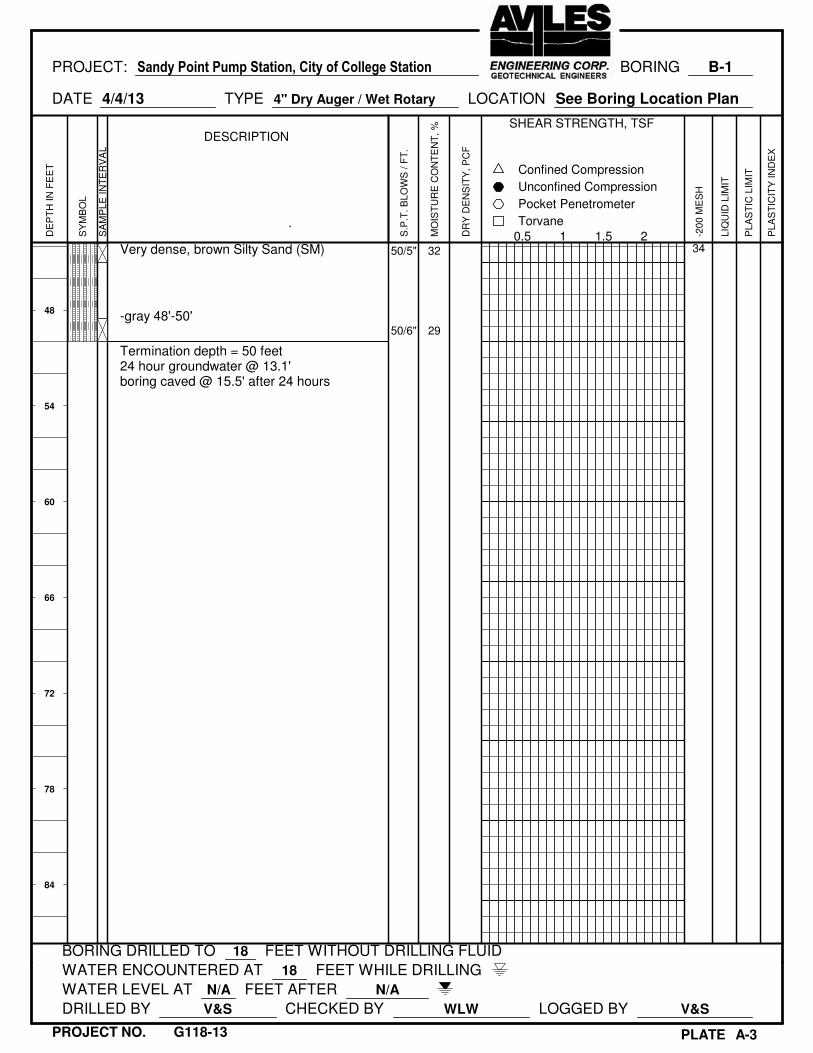
48
54
60
66
72
78
84
Very dense, brown Silty Sand (SM)
-gray 48'-50'
Termination depth = 50 feet
24 hour groundwater @ 13.1'
boring caved @ 15.5' after 24 hours
50/5"
50/6"
32
29
34
PROJECT: Sandy Point Pump Station, City of College Station BORING B-1
DATE 4/4/13 TYPE 4" Dry Auger / Wet Rotary LOCATION See Boring Location Plan
BORING DRILLED TO 18 FEET WITHOUT DRILLING FLUID
WATER ENCOUNTERED AT 18 FEET WHILE DRILLING
WATER LEVEL AT N/A FEET AFTER N/A
DRILLED BY V&S CHECKED BY WLW LOGGED BY V&S
PLATE A-3
DE
PT
H I
N F
EE
T
SY
MB
OL
SA
MP
LE
IN
TE
RV
AL
DESCRIPTION
.
S.P
.T.
BL
OW
S /
FT
.
MO
IST
UR
E C
ON
TE
NT
, %
DR
Y D
EN
SIT
Y,
PC
F
SHEAR STRENGTH, TSF
0.5 1 1.5 2
Torvane
Pocket Penetrometer
Unconfined Compression
Confined Compression
-2
00
ME
SH
LIQ
UID
LIM
IT
PL
AS
TIC
LIM
IT
PL
AS
TIC
ITY
IN
DE
X
PROJECT NO. G118-13

0
6
12
18
24
30
36
42
Fill: hard, brown Sandy Lean Clay (CL), with
silt seams and gravel
Fill: stiff, gray and brown Lean Clay (CL), with
gravel and ferrous stains
Fill: hard, brown Lean Clay (CL), with sand
seams and pockets
-gray, red, and brown 6'-8'
-gray 8'-12'
Medium dense, red and tan Silty Sand (SM),
with clay pockets
Medium dense, gray Clayey Sand (SC), with
fat clay pockets
Medium dense, red and tan Poorly Graded
Sand w/Clay (SP-SC)
Stiff to very stiff, light gray and tan Sandy
Lean Clay (CL), with silty sand seams
Very dense, light gray and tan Silty Sand
(SM), with clayey sand pockets
Very stiff to hard, light gray Fat Clay (CH),
with silt layers
-with abundant silt and sand layers 38'-40'
21
17
24
50/4"
16
15
11
10
15
18
12
21
17
10
16
25
30
31
114
110
118
96
51
38
12
27
49
32
26
56
14
14
16
15
26
13
35
16
11
30
PROJECT: Sandy Point Pump Station, City of College Station BORING B-2
DATE 4/4/13 TYPE 4" Dry Auger / Wet Rotary LOCATION See Boring Location Plan
BORING DRILLED TO 18 FEET WITHOUT DRILLING FLUID
WATER ENCOUNTERED AT 18 FEET WHILE DRILLING
WATER LEVEL AT 14.1 FEET AFTER 1/4 HR
DRILLED BY V&S CHECKED BY WLW LOGGED BY V&S
PLATE A-4
DE
PT
H I
N F
EE
T
SY
MB
OL
SA
MP
LE
IN
TE
RV
AL
DESCRIPTION
.
S.P
.T.
BL
OW
S /
FT
.
MO
IST
UR
E C
ON
TE
NT
, %
DR
Y D
EN
SIT
Y,
PC
F
SHEAR STRENGTH, TSF
0.5 1 1.5 2
Torvane
Pocket Penetrometer
Unconfined Compression
Confined Compression
-2
00
ME
SH
LIQ
UID
LIM
IT
PL
AS
TIC
LIM
IT
PL
AS
TIC
ITY
IN
DE
X
PROJECT NO. G118-13

48
54
60
66
72
78
84
Very dense, gray Clayey Sand (SC), with fat
clay pockets
-brown, with silty sand 48'-50'
Termination depth = 50 feet
24 hour groundwater @ 11.0'
boring caved @ 13.2' after 24 hours
50/2"
50/5"
31
33
49
PROJECT: Sandy Point Pump Station, City of College Station BORING B-2
DATE 4/4/13 TYPE 4" Dry Auger / Wet Rotary LOCATION See Boring Location Plan
BORING DRILLED TO 18 FEET WITHOUT DRILLING FLUID
WATER ENCOUNTERED AT 18 FEET WHILE DRILLING
WATER LEVEL AT 14.1 FEET AFTER 1/4 HR
DRILLED BY V&S CHECKED BY WLW LOGGED BY V&S
PLATE A-4
DE
PT
H I
N F
EE
T
SY
MB
OL
SA
MP
LE
IN
TE
RV
AL
DESCRIPTION
.
S.P
.T.
BL
OW
S /
FT
.
MO
IST
UR
E C
ON
TE
NT
, %
DR
Y D
EN
SIT
Y,
PC
F
SHEAR STRENGTH, TSF
0.5 1 1.5 2
Torvane
Pocket Penetrometer
Unconfined Compression
Confined Compression
-2
00
ME
SH
LIQ
UID
LIM
IT
PL
AS
TIC
LIM
IT
PL
AS
TIC
ITY
IN
DE
X
PROJECT NO. G118-13

0
6
12
18
24
30
36
42
Hard, brown Sandy Fat Clay (CH), with
ferrous stains
-with roots 0'-2'
-brown and gray, with sand partings 4'-6'
-gray and tan 6'-8'
-gray 8'-10'
Medium dense, tan Clayey Sand (SC)
-light gray 12'-16'
-red and tan 16'-20'
-with red and tan sandy clay layer 18'-20'
Medium dense to dense, orange and tan Silty
Sand (SM)
-boring caved at 26'
-red and tan, with fat clay layer 28'-30'
Stiff to hard, dark brown Fat Clay (CH), with
silt partings
-light brown, with silty sand seams 43'-45'
14
20
26
25
41
29
11
18
11
13
15
6
12
10
9
14
12
28
28
32
124
114
92
4.46
65
43
13
100
69
50
22
80
20
18
22
33
49
32
np
47
PROJECT: Sandy Point Pump Station, City of College Station BORING B-3
DATE 4/4/13 TYPE 4" Dry Auger / Wet Rotary LOCATION See Boring Location Plan
BORING DRILLED TO 30 FEET WITHOUT DRILLING FLUID
WATER ENCOUNTERED AT 29 FEET WHILE DRILLING
WATER LEVEL AT 23.8 FEET AFTER 1/4 HR
DRILLED BY V&S CHECKED BY WLW LOGGED BY V&S
PLATE A-5
DE
PT
H I
N F
EE
T
SY
MB
OL
SA
MP
LE
IN
TE
RV
AL
DESCRIPTION
.
S.P
.T.
BL
OW
S /
FT
.
MO
IST
UR
E C
ON
TE
NT
, %
DR
Y D
EN
SIT
Y,
PC
F
SHEAR STRENGTH, TSF
0.5 1 1.5 2
Torvane
Pocket Penetrometer
Unconfined Compression
Confined Compression
-2
00
ME
SH
LIQ
UID
LIM
IT
PL
AS
TIC
LIM
IT
PL
AS
TIC
ITY
IN
DE
X
PROJECT NO. G118-13
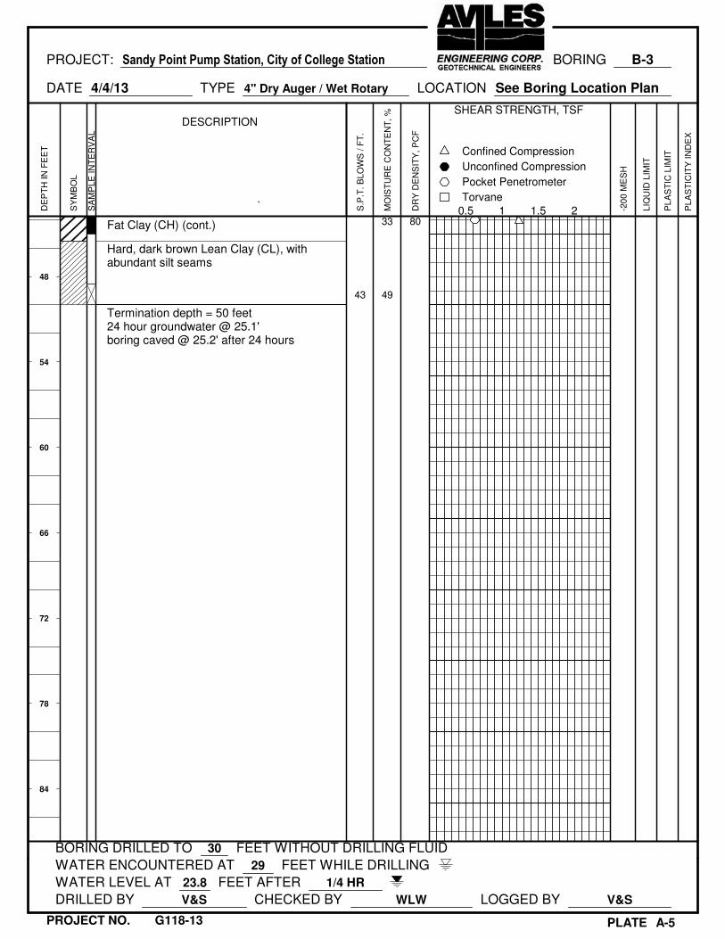
48
54
60
66
72
78
84
Fat Clay (CH) (cont.)
Hard, dark brown Lean Clay (CL), with
abundant silt seams
Termination depth = 50 feet
24 hour groundwater @ 25.1'
boring caved @ 25.2' after 24 hours
43
33
49
80
PROJECT: Sandy Point Pump Station, City of College Station BORING B-3
DATE 4/4/13 TYPE 4" Dry Auger / Wet Rotary LOCATION See Boring Location Plan
BORING DRILLED TO 30 FEET WITHOUT DRILLING FLUID
WATER ENCOUNTERED AT 29 FEET WHILE DRILLING
WATER LEVEL AT 23.8 FEET AFTER 1/4 HR
DRILLED BY V&S CHECKED BY WLW LOGGED BY V&S
PLATE A-5
DE
PT
H I
N F
EE
T
SY
MB
OL
SA
MP
LE
IN
TE
RV
AL
DESCRIPTION
.
S.P
.T.
BL
OW
S /
FT
.
MO
IST
UR
E C
ON
TE
NT
, %
DR
Y D
EN
SIT
Y,
PC
F
SHEAR STRENGTH, TSF
0.5 1 1.5 2
Torvane
Pocket Penetrometer
Unconfined Compression
Confined Compression
-2
00
ME
SH
LIQ
UID
LIM
IT
PL
AS
TIC
LIM
IT
PL
AS
TIC
ITY
IN
DE
X
PROJECT NO. G118-13

Symbol Description
Strata symbols
Fill
Clayey sand
Silty sand
Low plasticity
clay
Poorly graded sand
with clay
High plasticity
clay
Misc. Symbols
Water table depth
during drilling
Torvane
Pocket Penetrometer
Confined Compression
Subsequent water
table depth
Soil Samplers
Undisturbed thin wall
Shelby tube
Standard penetration test
KEY TO SYMBOLS
PLATE A-6

PLATE A-7

PLATE A-8

PLATE A-9

GRAIN SIZE ANALYSIS - SIEVE
Project : Sandy Point Pump Station Improvements Job No.: G118-13
Location of Project: Bryan, Texas Date of Testing: 4/9/2013
Sand
Gravel Coarse Fine Silt Clay
to Medium
Curve Boring Depth (ft) Cu Cc
1 B-1 4-6 N/A N/A
2 B-2 43-45 N/A N/A
3 B-3 14-16 N/A N/A
PLATE A-10
AVILES ENGINEERING CORPORATION
Consulting Engineers - Geotechnical, Construction Materials Testing, Environmental
Clayey Sand (SC)
Fill: Poorly Graded Sand w/Silt (SP-SM)
Clayey Sand (SC)
Soil Description
3" #43/4" #40 #200
0
10
20
30
40
50
60
70
80
90
100
0.00010.0010.010.1110100
Per
cen
tag
e P
ass
ing
(%
)
Diameter (mm)
Grain Size Analysis
Curve 1 Curve 2 Curve 3

APPENDIX B
Plate B-1 Allowable Accumulative Unit Skin Friction vs. Depth for Straight Sided Drilled Shafts
Plate B-2 Allowable Unit End Bearing vs. Depth for Straight Sided Drilled Shafts
Plate B-3 Allowable Compressive Load vs. Depth for Straight Sided Drilled Shafts
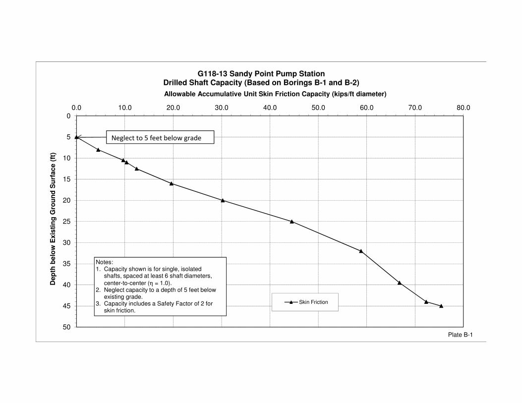
0
5
10
15
20
25
30
35
40
45
50
0.0 10.0 20.0 30.0 40.0 50.0 60.0 70.0 80.0
Dep
th b
elo
w E
xis
tin
g G
rou
nd
Su
rfa
ce (
ft)
Allowable Accumulative Unit Skin Friction Capacity (kips/ft diameter)
G118-13 Sandy Point Pump StationDrilled Shaft Capacity (Based on Borings B-1 and B-2)
Skin Friction
Notes:
1. Capacity shown is for single, isolated
shafts, spaced at least 6 shaft diameters,
center-to-center (η = 1.0).
2. Neglect capacity to a depth of 5 feet below
existing grade.
3. Capacity includes a Safety Factor of 2 for
skin friction.
Plate B-1
Neglect to 5 feet below grade
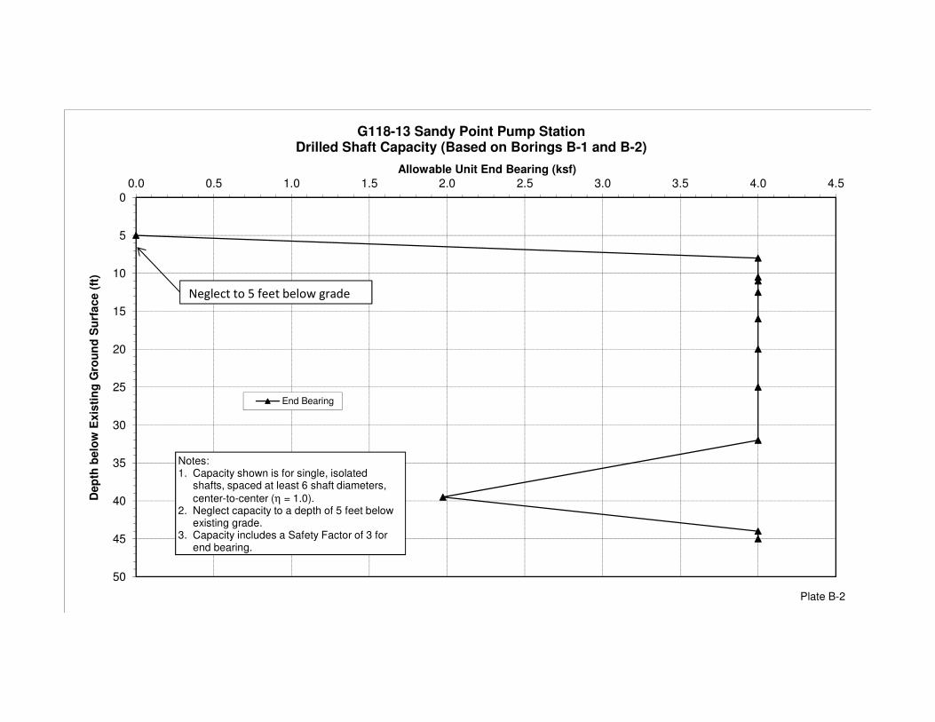
0
5
10
15
20
25
30
35
40
45
50
0.0 0.5 1.0 1.5 2.0 2.5 3.0 3.5 4.0 4.5
Dep
th b
elo
w E
xis
tin
g G
rou
nd
Su
rfa
ce (
ft)
Allowable Unit End Bearing (ksf)
G118-13 Sandy Point Pump StationDrilled Shaft Capacity (Based on Borings B-1 and B-2)
End Bearing
Notes:
1. Capacity shown is for single, isolated
shafts, spaced at least 6 shaft diameters,
center-to-center (η = 1.0).
2. Neglect capacity to a depth of 5 feet below
existing grade.
3. Capacity includes a Safety Factor of 3 for
end bearing.
Plate B-2
Neglect to 5 feet below grade

0
5
10
15
20
25
30
35
40
45
50
0 50 100 150 200 250 300 350 400
De
pth
belo
w E
xis
tin
g G
rou
nd
Su
rfa
ce (
ft)
Allowable Compressive Load (kips)
G118-13 Sandy Point Pump StationDrilled Shaft Capacity (Based on Borings B-1 and B-2)
24-in Dia. Shaft
36-in Dia. Shaft
48-in Dia. Shaft
Notes:
1. Allowable total capacity shown includesskin friction and end bearing.
2. Capacity shown is for single, isolated
shafts, spaced at least 6 shaft diameters,
center-to-center.
3. Neglect capacity to a depth of 5 feet below
existing grade.
4. Capacity includes a Safety Factor of 2 for
Plate B-3
Neglect to 5 feet below grade

APPENDIX C
Plate C-1 Recommended Geotechnical Design Parameters for Underground Utilities
Plate C-2 Load Coefficients for Pipe Loading
Plate C-3 Live Loads on Pipe Crossing Under Roadway
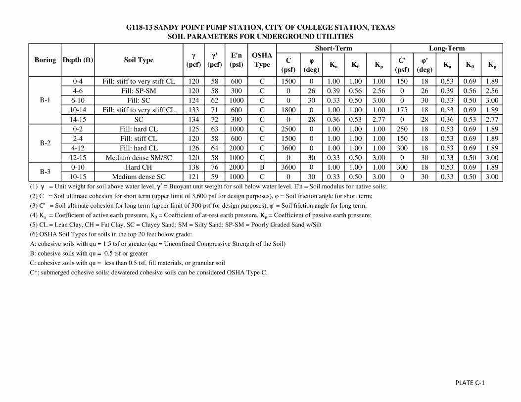
G118-13 SANDY POINT PUMP STATION, CITY OF COLLEGE STATION, TEXAS
SOIL PARAMETERS FOR UNDERGROUND UTILITIES
C
(psf)
φ
(deg)Ka K0 Kp
C'
(psf)
φ'
(deg)Ka K0 Kp
0-4 Fill: stiff to very stiff CL 120 58 600 C 1500 0 1.00 1.00 1.00 150 18 0.53 0.69 1.89
4-6 Fill: SP-SM 120 58 300 C 0 26 0.39 0.56 2.56 0 26 0.39 0.56 2.56
6-10 Fill: SC 124 62 1000 C 0 30 0.33 0.50 3.00 0 30 0.33 0.50 3.00
10-14 Fill: stiff to very stiff CL 133 71 600 C 1800 0 1.00 1.00 1.00 175 18 0.53 0.69 1.89
14-15 SC 134 72 300 C 0 28 0.36 0.53 2.77 0 28 0.36 0.53 2.77
0-2 Fill: hard CL 125 63 1000 C 2500 0 1.00 1.00 1.00 250 18 0.53 0.69 1.89
2-4 Fill: stiff CL 120 58 600 C 1500 0 1.00 1.00 1.00 150 18 0.53 0.69 1.89
4-12 Fill: hard CL 126 64 2000 C 3600 0 1.00 1.00 1.00 300 18 0.53 0.69 1.89
12-15 Medium dense SM/SC 120 58 1000 C 0 30 0.33 0.50 3.00 0 30 0.33 0.50 3.00
0-10 Hard CH 138 76 2000 B 3600 0 1.00 1.00 1.00 300 18 0.53 0.69 1.89
10-15 Medium dense SC 121 59 1000 C 0 30 0.33 0.50 3.00 0 30 0.33 0.50 3.00
(1) γ = Unit weight for soil above water level, γ’ = Buoyant unit weight for soil below water level. E'n = Soil modulus for native soils;
(2) C = Soil ultimate cohesion for short term (upper limit of 3,600 psf for design purposes), φ = Soil friction angle for short term;
(3) C' = Soil ultimate cohesion for long term (upper limit of 300 psf for design purposes), φ' = Soil friction angle for long term;
(4) Ka = Coefficient of active earth pressure, K0 = Coefficient of at-rest earth pressure, Kp = Coefficient of passive earth pressure;
(5) CL = Lean Clay, CH = Fat Clay, SC = Clayey Sand; SM = Silty Sand; SP-SM = Poorly Graded Sand w/Silt
(6) OSHA Soil Types for soils in the top 20 feet below grade:
A: cohesive soils with qu = 1.5 tsf or greater (qu = Unconfined Compressive Strength of the Soil)
B: cohesive soils with qu = 0.5 tsf or greater
C: cohesive soils with qu = less than 0.5 tsf, fill materials, or granular soil
C*: submerged cohesive soils; dewatered cohesive soils can be considered OSHA Type C.
Long-Term
Boring Depth (ft) Soil Typeγ
(pcf)
γ'
(pcf)
E'n
(psi)
B-1
B-2
B-3
OSHA
Type
Short-Term
PLATE C-1

PLATE C-2Reference: US Army Corps of Engineers Engineering Manual, EM 1110-2-2909, Oct. 31, 1997, Figure 2-5.

PLATE C-3

APPENDIX D
Plate D-1 Critical Heights of Cuts in Nonfissured Clays
Plate D-2 Maximum Allowable Slopes
Plate D-3 A Combination of Bracing and Open Cuts
Plate D-4 Lateral Pressure Diagrams for Open Cuts in Cohesive Soil-Long Term Conditions
Plate D-5 Lateral Pressure Diagrams for Open Cuts in Cohesive Soil-Short Term Conditions
Plate D-6 Lateral Pressure Diagrams for Open Cuts in Sand
Plate D-7 Bottom Stability for Braced Excavation in Clay
Plate D-8 Thrust Force Calculation
Plate D-9 Thrust Force Example Calculation
Plate D-10 Design Parameters for Bearing Thrust Block
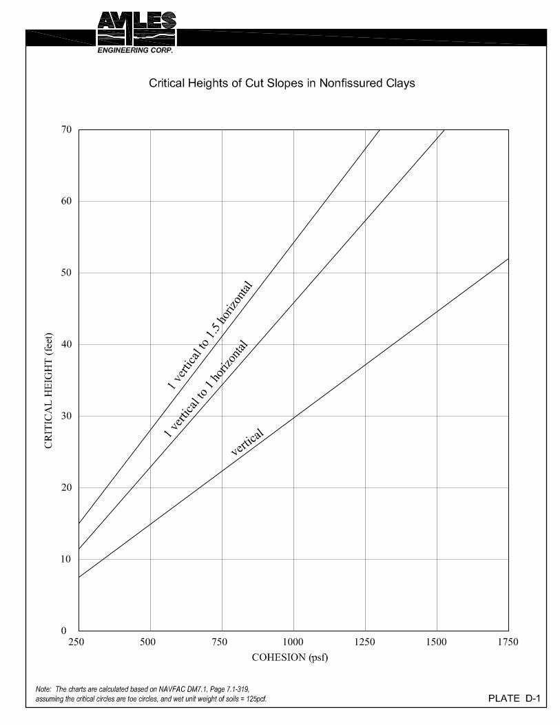
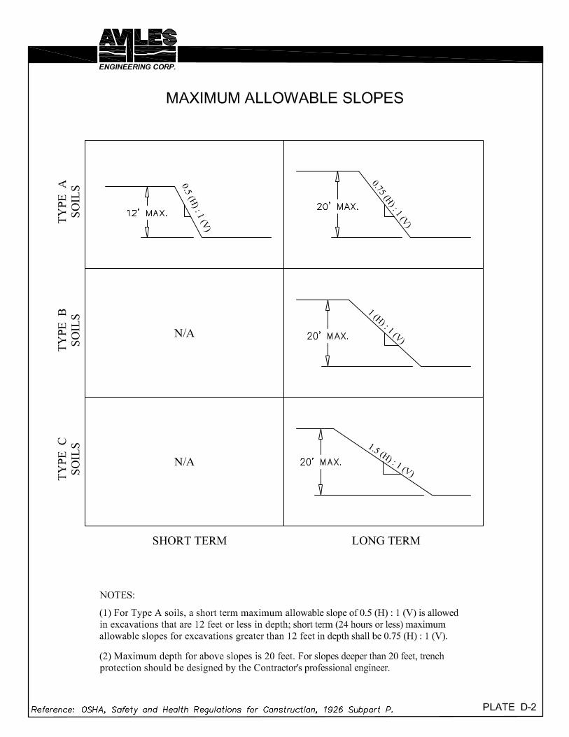


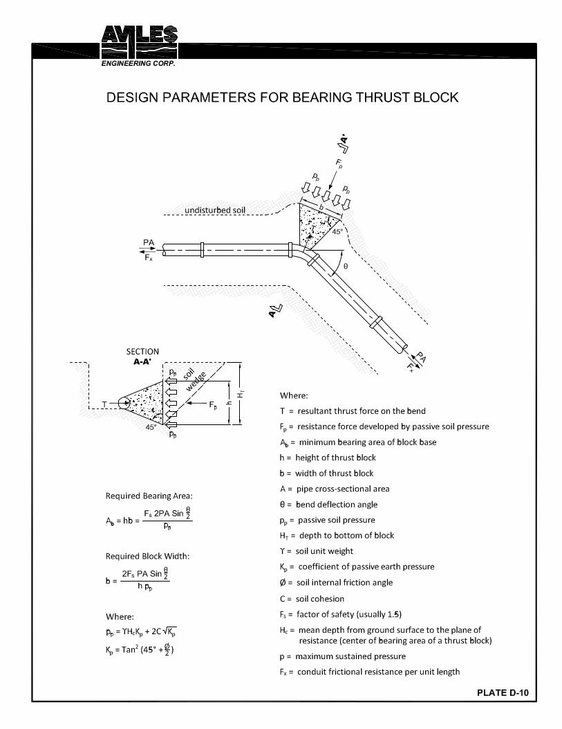

APPENDIX E
A&B Laboratories Chemical Analyses

L A B O R A T O R Y T E S T R E S U L T S
Soil
13041512.01
Sample Matrix
Job Sample ID:
AnalystDate TimeQReg LimitRpt LimitDFUnitsResultParameter/Test DescriptionTest Method
B-3,2'-4'
Other Information:
Time Collected:
Client Sample ID:
Date Collected:
Wilber WangAttn:
G118-13 Sandy Point Pump Station,Bryan, TexasProject Name:
Aviles EngineeringClient Name:
Date13041512Job ID :
5/8/2013
04/04/13
ResistivityEPA 120.1
SR05/08/13 10:50H311ohm-cm14124Resistivity¹
Water Soluble AnionsEPA 300.0
XA04/30/13 08:5311mg/Kg99.6Chloride
XA04/30/13 08:5311mg/Kg10.6Sulfate
Corrosivity, pHSW-846 9045D
SR05/01/13 09:55H31s.u.7.02pH
SR05/01/13 09:55H31s.u.22.5Temperature when read, °C¹
¹-Parameter not available for accreditation
Page 3 of 8
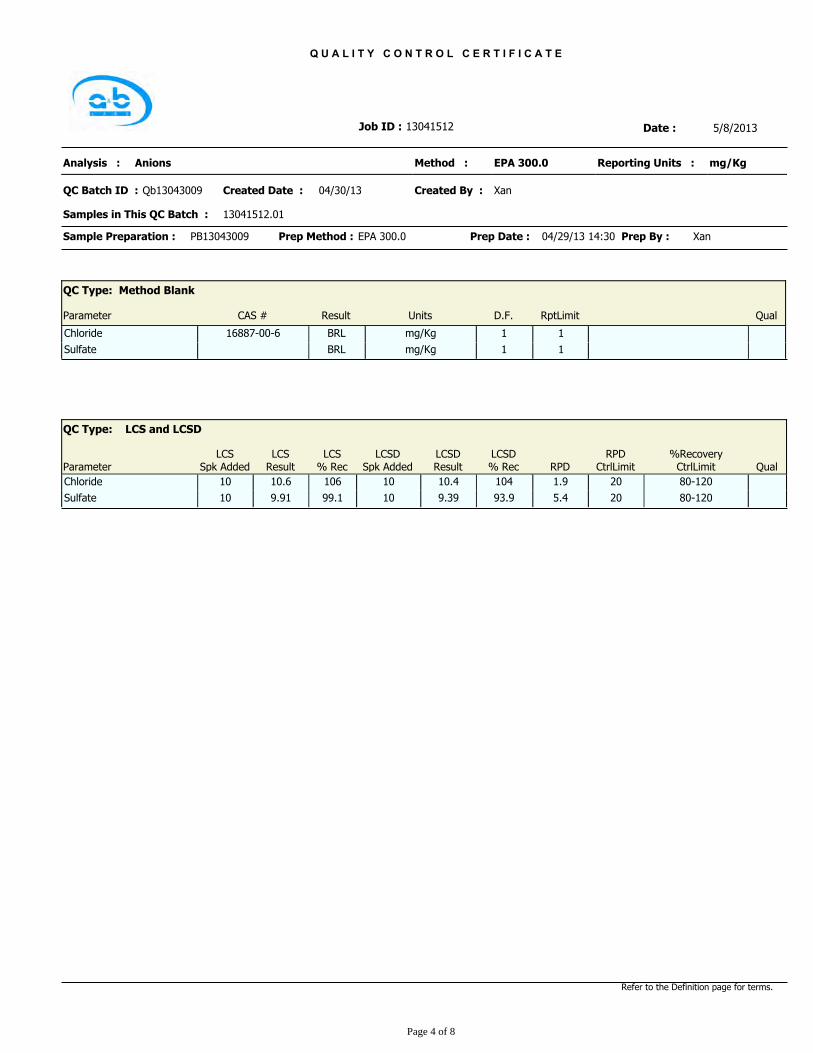
Q U A L I T Y C O N T R O L C E R T I F I C A T E
Date :13041512Job ID :
Xan
Samples in This QC Batch :
Qb13043009
Anions
13041512.01
Reporting Units :
04/30/13QC Batch ID :
Method :
Created Date :
Analysis :
Created By :
mg/KgEPA 300.0
5/8/2013
Prep Date : 04/29/13 14:30EPA 300.0Prep Method :PB13043009Sample Preparation : XanPrep By :
QC Type: Method Blank
D.F. RptLimitParameter Result Units QualCAS #
mg/Kg 1BRL 1Chloride 16887-00-6
mg/Kg 1BRL 1Sulfate
%RecoveryCtrlLimit
LCSDResult
LCSResult
RPDCtrlLimitRPD
LCSSpk Added
LCSD% Rec
LCS% RecParameter
LCSDSpk Added
QC Type: LCS and LCSD
Qual
1.910410 80-120106 2010.6Chloride 10 10.4
5.493.910 80-12099.1 209.91Sulfate 10 9.39
Refer to the Definition page for terms.
Page 4 of 8
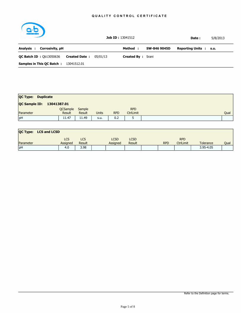
Q U A L I T Y C O N T R O L C E R T I F I C A T E
Date :13041512Job ID :
Srani
Samples in This QC Batch :
Qb13050636
Corrosivity, pH
13041512.01
Reporting Units :
05/01/13QC Batch ID :
Method :
Created Date :
Analysis :
Created By :
s.u.SW-846 9045D
5/8/2013
QC Type: Duplicate
13041387.01QC Sample ID:
Parameter UnitsSampleResult QualRPD
RPDCtrlLimit
QCSampleResult
s.u.pH 11.47 0.2 511.49
ToleranceLCSDResult
LCSResult
RPDCtrlLimitRPD
LCSAssignedParameter
LCSDAssigned
QC Type: LCS and LCSD
Qual
4.0 3.95-4.053.98pH
Refer to the Definition page for terms.
Page 5 of 8

Q U A L I T Y C O N T R O L C E R T I F I C A T E
Date :13041512Job ID :
Srani
Samples in This QC Batch :
Qb13050837
Resistivity
13041512.01
Reporting Units :
05/08/13QC Batch ID :
Method :
Created Date :
Analysis :
Created By :
ohm-cmEPA 120.1
5/8/2013
QC Type: Method Blank
D.F. RptLimitParameter Result Units QualCAS #
ohm-cm 1>500000 1Resistivity
QC Type: Duplicate
13041512.01QC Sample ID:
Parameter UnitsSampleResult QualRPD
RPDCtrlLimit
QCSampleResult
ohm-cmResistivity 14471 2.4 2014124
%RecoveryCtrlLimit
LCSDResult
LCSResult
RPDCtrlLimitRPD
LCSSpk Added
LCSD% Rec
LCS% RecParameter
LCSDSpk Added
QC Type: LCS and LCSD
Qual
10000 80-12097.79766Resistivity
Refer to the Definition page for terms.
Page 6 of 8

General Term Definition
BRL
Front-Wt
Below Reporting Limit
Front Weight
Back WeightBack-Wt
cfu colony-forming units
Conc. Concentration
D.F. Dilution Factor
LCS Laboratory Check Standard
LCSD Laboratory Check Standard Duplicate
MS Matrix Spike
MSD Matrix Spike Duplicate
Molecular WeightMW
RPD
ppm parts per million
Relative Percent Difference
TNTC Too numerous to count
Post-Wt
Pre-Wt Previous Weight
Q Qualifier
RegLimit Regulatory Limit
RptLimit Reporting Limit
T Time
Post Weight
surr Surrogate
SDL Sample Detection Limit
13060782
L A B O R A T O R Y T E R M A N D Q U A L I F I E R D E F I N I T I O N R E P O R T
Date:Job ID : 6/24/2013
Qualifier Definition
Sample was received and analyzed past holding time.H3
Page 2 of 8
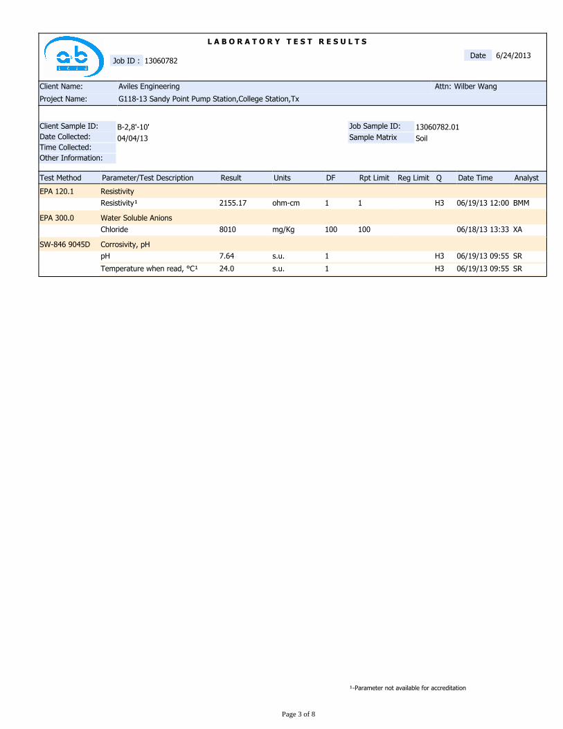
L A B O R A T O R Y T E S T R E S U L T S
Soil
13060782.01
Sample Matrix
Job Sample ID:
AnalystDate TimeQReg LimitRpt LimitDFUnitsResultParameter/Test DescriptionTest Method
B-2,8'-10'
Other Information:
Time Collected:
Client Sample ID:
Date Collected:
Wilber WangAttn:
G118-13 Sandy Point Pump Station,College Station,TxProject Name:
Aviles EngineeringClient Name:
Date13060782Job ID :
6/24/2013
04/04/13
ResistivityEPA 120.1
BMM06/19/13 12:00H311ohm-cm2155.17Resistivity¹
Water Soluble AnionsEPA 300.0
XA06/18/13 13:33100100mg/Kg8010Chloride
Corrosivity, pHSW-846 9045D
SR06/19/13 09:55H31s.u.7.64pH
SR06/19/13 09:55H31s.u.24.0Temperature when read, °C¹
¹-Parameter not available for accreditation
Page 3 of 8
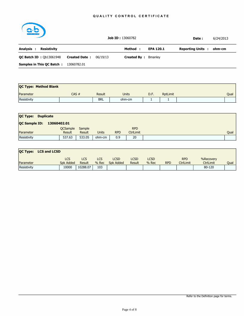
Q U A L I T Y C O N T R O L C E R T I F I C A T E
Date :13060782Job ID :
Bmanley
Samples in This QC Batch :
Qb13061948
Resistivity
13060782.01
Reporting Units :
06/19/13QC Batch ID :
Method :
Created Date :
Analysis :
Created By :
ohm-cmEPA 120.1
6/24/2013
QC Type: Method Blank
D.F. RptLimitParameter Result Units QualCAS #
ohm-cm 1BRL 1Resistivity
QC Type: Duplicate
13060402.01QC Sample ID:
Parameter UnitsSampleResult QualRPD
RPDCtrlLimit
QCSampleResult
ohm-cmResistivity 537.63 0.9 20533.05
%RecoveryCtrlLimit
LCSDResult
LCSResult
RPDCtrlLimitRPD
LCSSpk Added
LCSD% Rec
LCS% RecParameter
LCSDSpk Added
QC Type: LCS and LCSD
Qual
10000 80-12010310288.07Resistivity
Refer to the Definition page for terms.
Page 4 of 8

Q U A L I T Y C O N T R O L C E R T I F I C A T E
Date :13060782Job ID :
Srani
Samples in This QC Batch :
Qb13062438
Corrosivity, pH
13060782.01
Reporting Units :
06/19/13QC Batch ID :
Method :
Created Date :
Analysis :
Created By :
s.u.SW-846 9045D
6/24/2013
QC Type: Duplicate
13060782.01QC Sample ID:
Parameter UnitsSampleResult QualRPD
RPDCtrlLimit
QCSampleResult
s.u.pH 7.65 0.1 57.64
ToleranceLCSDResult
LCSResult
RPDCtrlLimitRPD
LCSAssignedParameter
LCSDAssigned
QC Type: LCS and LCSD
Qual
4.0 3.95-4.054.0pH
Refer to the Definition page for terms.
Page 5 of 8

Q U A L I T Y C O N T R O L C E R T I F I C A T E
Date :13060782Job ID :
Xan
Samples in This QC Batch :
Qb13062445
Anions
13060782.01
Reporting Units :
06/21/13QC Batch ID :
Method :
Created Date :
Analysis :
Created By :
mg/KgEPA 300.0
6/24/2013
Prep Date : 06/14/13 16:00EPA 300.0Prep Method :PB13062432Sample Preparation : XanPrep By :
QC Type: Method Blank
D.F. RptLimitParameter Result Units QualCAS #
mg/Kg 1BRL 1Chloride 16887-00-6
%RecoveryCtrlLimit
LCSDResult
LCSResult
RPDCtrlLimitRPD
LCSSpk Added
LCSD% Rec
LCS% RecParameter
LCSDSpk Added
QC Type: LCS and LCSD
Qual
10.399.210 90-110110 2011Chloride 10 9.92
Refer to the Definition page for terms.
Page 6 of 8