GEOTECHNICAL FILTERS - THE IMPORTANT LINK IN SCOUR … 2.pdf · 2016-09-27 · 1 GEOTECHNICAL...
16
1 GEOTECHNICAL FILTERS - THE IMPORTANT LINK IN SCOUR PROTECTION MICHAEL H. HEIBAUM Federal Waterways Engineering & Research Institute Kussmaulstr. 17 – 76187 Karlsruhe – Germany Any scour protection system needs two essential parts: the armour and the filter. The armour pro- vides protection against the direct hydraulic and - if acting - mechanical loading. The voids in per- meable armour material, e.g. riprap or concrete elements, are too large to prevent erosion of the sub- soil through the armour. Only a filter will keep the grains of the subsoil in place while the armour provides the necessary strength. A filter can be either granular or geosynthetic. Filters in scour protection measures are loaded by unsteady, turbulent, pulsating and reversing flow. Most of the design rules for geosynthetic and granular filters are developed for unidirectional laminar flow. Only some are reliable in the case of dynamic hydraulic loading. The correct placement of a filter is as important as its design. In many scour countermeasures it is necessary to place the filter under water, which creates additional problems for both granular and geotextile filters. Therefore, every placement procedure has to be planned very carefully. Geotextile containers may be the solution for the safe placement of filters. 1 Introduction It goes without saying that an armour layer is needed to protect the subsoil successfully from scouring when severe hydraulic loads are acting. At first sight, such an armour might be sufficient to withstand the hydraulic load when it is made of elements that are just large enough. Yet it is a fundamental error to think that scouring will only occur if waves and currents dislodge the armour material. Such an error may be the reason why, in some places, riprap is considered a temporary countermeasure only. Such an opinion may originate from experience with armour layers without a filter beneath. The size of the voids between the elements of the armour layer increases with that of the elements. Erosion will occur if the elements below the armour are small enough to pass through the voids. This is referred to as 'winnowing' or, in the geotechnical sense, 'contact erosion'. Winnowing or contact erosion will cause material loss, resulting in a settlement trough comparable to scouring of the surface. Therefore, a filter layer is a must to prevent erosion of the subsoil. It will only be possible to dispense with a filter when the hydraulic load at the subsoil-armour interface is permanently (!) so low that the finer grains will definitely not be eroded. That may be the case if the armour layer is so thick that the energy of the hydraulic load acting on the armour surface is dissipated in the armour layer and is sufficiently low at the subsoil-armour interface. So, generally speaking, either a filter has to be designed for the subsoil-armour interface or the hydrau- lic load, predominantly the hydraulic gradient, has to be reduced in order to achieve a long-lasting scour countermeasure. It is often easier to increase the resistance, e.g. by choosing a strong armour with a well-designed filter, than to decrease the load or action, e.g. by appropriate hydraulic
Transcript of GEOTECHNICAL FILTERS - THE IMPORTANT LINK IN SCOUR … 2.pdf · 2016-09-27 · 1 GEOTECHNICAL...

1
GEOTECHNICAL FILTERS - THE IMPORTANT LINK IN SCOUR PROTECTION
MICHAEL H. HEIBAUM Federal Waterways Engineering & Research Institute
Kussmaulstr. 17 – 76187 Karlsruhe – Germany
Any scour protection system needs two essential parts: the armour and the filter. The armour pro-vides protection against the direct hydraulic and - if acting - mechanical loading. The voids in per-meable armour material, e.g. riprap or concrete elements, are too large to prevent erosion of the sub-soil through the armour. Only a filter will keep the grains of the subsoil in place while the armour provides the necessary strength. A filter can be either granular or geosynthetic.
Filters in scour protection measures are loaded by unsteady, turbulent, pulsating and reversing flow. Most of the design rules for geosynthetic and granular filters are developed for unidirectional laminar flow. Only some are reliable in the case of dynamic hydraulic loading.
The correct placement of a filter is as important as its design. In many scour countermeasures it is necessary to place the filter under water, which creates additional problems for both granular and geotextile filters. Therefore, every placement procedure has to be planned very carefully. Geotextile containers may be the solution for the safe placement of filters.
1 Introduction
It goes without saying that an armour layer is needed to protect the subsoil successfully from scouring when severe hydraulic loads are acting. At first sight, such an armour might be sufficient to withstand the hydraulic load when it is made of elements that are just large enough. Yet it is a fundamental error to think that scouring will only occur if waves and currents dislodge the armour material. Such an error may be the reason why, in some places, riprap is considered a temporary countermeasure only. Such an opinion may originate from experience with armour layers without a filter beneath.
The size of the voids between the elements of the armour layer increases with that of the elements. Erosion will occur if the elements below the armour are small enough to pass through the voids. This is referred to as 'winnowing' or, in the geotechnical sense, 'contact erosion'. Winnowing or contact erosion will cause material loss, resulting in a settlement trough comparable to scouring of the surface. Therefore, a filter layer is a must to prevent erosion of the subsoil. It will only be possible to dispense with a filter when the hydraulic load at the subsoil-armour interface is permanently (!) so low that the finer grains will definitely not be eroded. That may be the case if the armour layer is so thick that the energy of the hydraulic load acting on the armour surface is dissipated in the armour layer and is sufficiently low at the subsoil-armour interface. So, generally speaking, either a filter has to be designed for the subsoil-armour interface or the hydrau-lic load, predominantly the hydraulic gradient, has to be reduced in order to achieve a long-lasting scour countermeasure.
It is often easier to increase the resistance, e.g. by choosing a strong armour with a well-designed filter, than to decrease the load or action, e.g. by appropriate hydraulic

2
training measures. To design an armour system properly, it has to be taken into account that the hydraulic load differs somewhat from other filter applications such as drains, for example. It is an important requirement that filter criteria both at the subsoil-filter inter-face and at the filter-armour interface are satisfied. Most of the design rules for filters are developed for m gravel or smaller grains and for unidirectional and laminar flow. Filters used in scour protection measures are loaded by unsteady, turbulent, pulsating and re-versing flow. So the rules for filters must be checked to ensure they are reliable in the case of such dynamic hydraulic loading. Additionally, the development of excess pore water pressure in the subsoil due to rapid changes in the hydraulic head may complicate the design of the appropriate filter (Köhler 1993).
To design a filter, two criteria have to be fulfilled: I) The finer material has to be re-tained (a marginal loss may be allowed) and II) permeability must not decrease signifi-cantly in order to avoid a build-up of pore water pressure. These criteria conflict. There-fore, any design has to be carried out within narrow margins. On the other hand, the design should be kept as simple as possible. The approaches are usually grouped into "geometrical" and "hydraulic" criteria. Geometrical criteria define limit values for grain and/or void diameters to hinder the transport of finer particles through the voids of the coarser material. Hydraulic criteria define a limit value for the hydraulic gradient at which the transport of particles begins. The grain (or void) size distribution has to be known when geometrical criteria are used while the application of hydraulic criteria requires data on the flow velocity and/or the hydraulic gradient at the sublayer-filter interface. Both grain size distribution and/or hydraulic gradient often vary greatly. Since the grain size distribution is much easier to obtain than hydraulic gradients, geometrical criteria are better known and used more often.
2 Geometrical criteria for granular filters
2.1 Geometrical criteria for cohesionless material
The criteria discussed here are referred to as geometrical criteria because the main pa-rameter is a geometrical value, e.g. the grain diameter dx, i.e. the grain size d at which x% by weight of the total soil particles are smaller, also called "x% passing size". The usual parameter is the ratio of the grain size of the filter to that of the base, e.g. d15,F / d85,B (grain size at 15% passing of the filter and at 85% passing of the base soil). Most of the criteria are results obtained in numerous tests and are therefore empirical; they are often restricted as to the coefficients of uniformity of filter and subsoil or the grain size, which is often forgotten. Theoretical approaches are the assumption of the grains as spheres and probability-based approaches.
What is possibly the oldest filter criterion is based on a model of spheres: Prinz (1923) called for a ratio of dF / dB ≤ 4.42, which is in between the extreme conditions described by Sichard (1952), i.e. dF / dB ≤ 2.42 for the maximum void ratio (equal
3
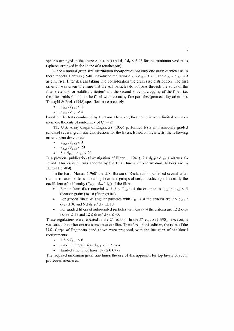
spheres arranged in the shape of a cube) and dF / dB ≤ 6.46 for the minimum void ratio (spheres arranged in the shape of a tetrahedron).
Since a natural grain size distribution incorporates not only one grain diameter as in these models, Bertram (1940) introduced the ratios d15,F / d85,B B ≈ 6 and d15,F / d15,B ≈ 9 as empirical filter designs taking into consideration the grain size distribution. The first criterion was given to ensure that the soil particles do not pass through the voids of the filter (retention or stability criterion) and the second to avoid clogging of the filter, i.e. the filter voids should not be filled with too many fine particles (permeability criterion). Terzaghi & Peck (1948) specified more precisely
• d15,F / d85,B ≤ 4 • d15,F / d15,B ≥ 4
based on the tests conducted by Bertram. However, these criteria were limited to maxi-mum coefficients of uniformity of CU = 2!
The U.S. Army Corps of Engineers (1953) performed tests with narrowly graded sand and several grain size distributions for the filters. Based on these tests, the following criteria were developed:
• d15,F / d85,B ≤ 5 • d50,F / d50,B ≤ 25 • 5 ≤ d15,F / d15,B ≤ 20.
In a previous publication (Investigation of Filter…, 1941), 5 ≤ d15,F / d15,B ≤ 40 was al-lowed. This criterion was adopted by the U.S. Bureau of Reclamation (below) and in HEC-11 (1989).
In the Earth Manual (1960) the U.S. Bureau of Reclamation published several crite-ria – also based on tests – relating to certain groups of soil, introducing additionally the coefficient of uniformity (CU,F = d60 / d10) of the filter:
• For uniform filter material with 3 ≤ CU,F ≤ 4 the criterion is d50,F / d50,B ≤ 5 (coarser grains) to 10 (finer grains).
• For graded filters of angular particles with CU,F > 4 the criteria are 9 ≤ d50,F / d50,B ≤ 30 and 6 ≤ d15,F / d15,B ≤ 18.
• For graded filters of subrounded particles with CU,F > 4 the criteria are 12 ≤ d50,F / d50,B ≤ 58 and 12 ≤ d15,F / d15,B ≤ 40.
These regulations were repeated in the 2nd edition. In the 3rd edition (1998), however, it was stated that filter criteria sometimes conflict. Therefore, in this edition, the rules of the U.S. Corps of Engineers cited above were proposed, with the inclusion of additional requirements:
• 1.5 ≤ CU,F ≤ 8 • maximum grain size d100,F < 37.5 mm • limited amount of fines (d5,F ≥ 0.075).
The required maximum grain size limits the use of this approach for top layers of scour protection measures.

4
However, another publication of the Bureau of Reclamation (Design of small dams, 1977) repeated the Corps' requirements for graded granular filters (CU,F > 4) and adopted the Corps' earlier and wider range for the permeability criterion:
• 5 ≤ d15,F / d15,B ≤ 40 Sublayers below riprap revetments are explicitly included, but most armour layers have a coefficient of uniformity CU < 4.
On the other hand, in ‛Design of coastal revetments’ (1995), the U.S. Army Corps of Engineers reduces the stability criterion to the Terzaghi criterion:
• d15,F / d85,B < 4 (instead of ≤ 5). For larger elements, it is proposed that the d15,F of the armour material be determined from the stone weight W
• d15,F = k∆ (W / γr)1/3 where γr = total specific weight of the armour unit, k∆ = layer coefficient (k∆ = 1.0 for quarrystones, 0.94 for dolos, 1.04 for tetrapods and 1.13 for tribars).
For larger elements, the Coastal Engineering Manual (2003) allows the weight to be used directly for the stability criterion instead of the grain diameter:
• 15 ≤ W50,F / W50,B ≤ 20 This is rather narrow since for the stone diameter the cubic root applies and it reads 2.5 ≤ d50,F / d50,B ≤ 2.7 if there is no difference in the specific weight. Additionally, the inter-nal stability of the filter has to be verified:
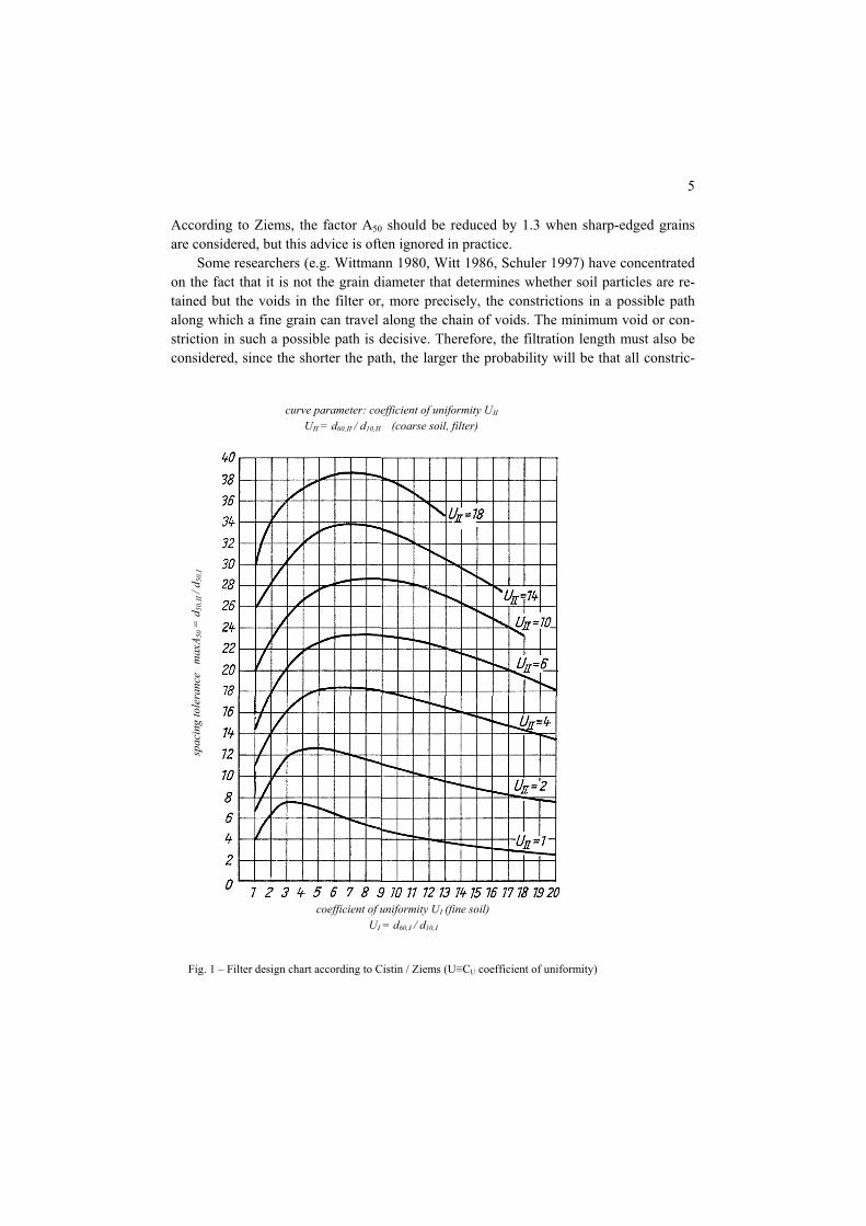
• d60,F / d10,F < 10. While these approaches became well known in the USA, the Terzaghi approach was mostly used in Central Europe, with the limits of application frequently being neglected. In Eastern Europe, criteria proposed by Cistin (1968) became very popular. Further tests were added by Ziems (1968). After his early death, his findings were collected and pub-lished by Busch & Luckner (1973). This approach became known as the ‛Cistin/Ziems approach’. A design chart was developed that enabled filters to be designed for a very wide spectrum of grain size distributions of filter and base soil (Fig.1). According to this approach the mean diameter d50,F of the filter material must not exceed the mean diameter d50,B of the base soil multiplied by the factor A50. The factor A50 depends on the coeffi-cient of uniformity CU,B (UI) of the soil and the coefficient of uniformity CU,F (UII) of the filter. The design chart incorporates a factor of safety of η = 1.5.
The tests taken as a basis for the design chart were performed with hydraulic gradi-ents up to i = 9, coefficients of uniformity of CU ≤ 20 for filter and soil and with grain diameters of 4mm ≥ dF ≥ 100mm for the filter and 0.1mm ≥ dB ≥ 30mm for the subsoil. The approach is also valuable for smaller grain sizes. Larger grains should be considered with care, since the flow may be turbulent and the findings of the test were achieved with laminar flow. The authors recommend tests when larger coefficients of uniformity are observed. In practice, the approach has been successfully applied both to narrowly and to well graded filters, including riprap material with a diameter of approx. d50 ≈ 250 mm.
5
According to Ziems, the factor A50 should be reduced by 1.3 when sharp-edged grains are considered, but this advice is often ignored in practice.
Some researchers (e.g. Wittmann 1980, Witt 1986, Schuler 1997) have concentrated on the fact that it is not the grain diameter that determines whether soil particles are re-tained but the voids in the filter or, more precisely, the constrictions in a possible path along which a fine grain can travel along the chain of voids. The minimum void or con-striction in such a possible path is decisive. Therefore, the filtration length must also be considered, since the shorter the path, the larger the probability will be that all constric-
curve parameter: coefficient of uniformity UΙΙ UΙΙ = d60,ΙΙ / d10,ΙΙ (coarse soil, filter)
coefficient of uniformity UΙ (fine soil) UΙ = d60,Ι / d10,Ι
spac
ing
tole
ranc
e m
axA 5
0 = d
50,ΙΙ
/ d 5
0,Ι
Fig. 1 – Filter design chart according to Cistin / Ziems (U≡CU coefficient of uniformity)
6
tions are large enough to allow the particle to pass. The criterion developed by Wittmann (1980) for sand calls for a filtration length of approximately 25 • d50,F. This rule is not applicable to coarser material such as riprap or armour stones. A filtration length of approx. 5 m (e.g. riprap) or more than 20 m (large coastal armour stones) might be re-quired for a filter with larger elements. Most of these design proposals incorporating probability functions need a considerable amount of computing, so the application will remain restricted to research activities.
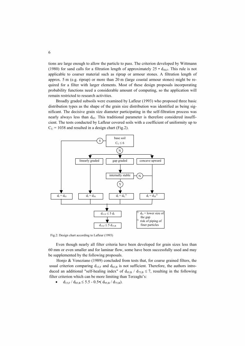
Broadly graded subsoils were examined by Lafleur (1993) who proposed three basic distribution types as the shape of the grain size distribution was identified as being sig-nificant. The decisive grain size diameter participating in the self-filtration process was nearly always less than d85. This traditional parameter is therefore considered insuffi-cient. The tests conducted by Lafleur covered soils with a coefficient of uniformity up to CU = 1038 and resulted in a design chart (Fig.2).
Even though nearly all filter criteria have been developed for grain sizes less than 60 mm or even smaller and for laminar flow, some have been successfully used and may be supplemented by the following proposals.
Honjo & Veneziano (1989) concluded from tests that, for coarse grained filters, the usual criterion comparing d15,F and d85,B is not sufficient. Therefore, the authors intro-duced an additional "self-healing index" of d95,B / d75,B ≤ 7, resulting in the following filter criterion which can be more limiting than Terzaghi’s:
• d15,F / d85,B ≤ 5.5 - 0.5•( d95,B / d75,B).
gap graded concave upward linearly graded
base soil CU ≤ 6
internally stable
dI = d85 dI = d50 dI = dG1) dI = d30
2)
d15,F ≤ 5 dI
d15,F ≤ 5 d15,B
Y
N
Y
N
1) dG = lower size of the gap
2) risk of piping of finer particles
Fig.2: Design chart according to Lafleur (1993)

7
Myogahara et al (1993) studied the behaviour of coarse material used for rock fill
dams. In model tests, high gradients were applied, resulting in turbulent flow. In these tests using rock material up to a diameter of 53 mm the authors found that the usual crite-rion d15,F / d85,B is not sufficient to assess the stability of a rock layer on a finer material. Therefore, they proposed assessing d15,F / d30,B as follows:
• d15,F / d30,B ≤ 40 stability for all gradients • d15,F / d30,B ≤ 80 stability for all gradients i < 20 • d15,F / d30,B > 80 instability
However, these criteria permit very large spacing of the filter and the base and should only be used after additional verification.
2.2 Geometrical criteria for cohesive soils
Filtration criteria consider the transportation of single grains of a soil. Cohesive material cannot be treated the same way since the particles form aggregates, protecting the indi-vidual particles from being washed away by the flow. Locke et al. (2000) performed tests that showed the erosion of aggregates larger than the particles found by the usual sedi-mentation test on cohesive soils. However, the size of such particles will be difficult to estimate as it depends on the susceptibility of the soil to dispersion. Depending on the plasticity and the undrained shear strength of the base material, the ratio of the grain size diameter of the filter to that of the base may be much higher than for cohesionless mate-rial. Sherard et al. (1984) proposed
• d15,F / d85,B ≤ 5 for sandy silt and clay with 0.1 ≤ d85,B ≤ 0.5 mm • d15,F ≤ 0.5 mm for clay with 0.03 ≤ d85,B ≤ 0.1 mm • d15,F ≤ 0.3 mm for silt with low cohesion and little sand (0.03 ≤ d85,B ≤ 0.1 mm) • d15,F ≤ 0.2 mm for clay with d85,B ≤ 0.02 mm
A rather generalized approach based on practical experience is given in the MAK rec-ommendations (BAW 1989). It is dependent on the plasticity index IP and the undrained shear strength cu:
• d10,F ≤ 0.2 and d60,F ≤ 0.7 for cohesive material with IP < 0.15 and cu ≥ 10 kPa • d10,F ≤ 0.6 and d60,F ≤ 2,0 for cohesive material with IP ≥ 0.15 and cu ≥ 10 kPa
3 Geometrical criteria for geotextile filters
Geosynthetic sheets were introduced as filters approximately 30-40 years ago. The most important difference is the fact that the filter does not comprise single grains but a con-tinuous sheet of fibres with the result that no erosion or segregation can occur. Geotextile filters are very light so they have the advantage of being easy to transport. However, their disadvantage is that hydraulic loads can easily dislodge an entire sheet. There are woven and nonwoven fabrics available for filter applications. The filtration capacity of woven geotextiles appears to be limited to narrowly graded grain size distributions. However,
8
tests have also shown that certain products may perform well. The reasons for these con-tradictory findings are not properly understood yet. Experience gained to date indicates that nonwoven fabrics can be designed for nearly any given grain size distribution of the subsoil.
Filter rules are numerous, but still there is a lot of discussion about the "best" geotex-tile filter. Most filter rules are based on the opening size (Ow, O90,w, O95, EOS, AOS) and may be used as a first estimate or may be sufficient when the hydraulic load at the inter-face of soil and geotextile is low. For scour protection, flows that are always turbulent and often reversing have to be considered. Therefore, empirical criteria can be only a first estimate and performance tests may be necessary, e.g. turbulence tests (BAW 1993), where it has to be proven that the amount of soil washed through the geotextile is limited and decreases with time when loaded by a turbulent reversing flow.
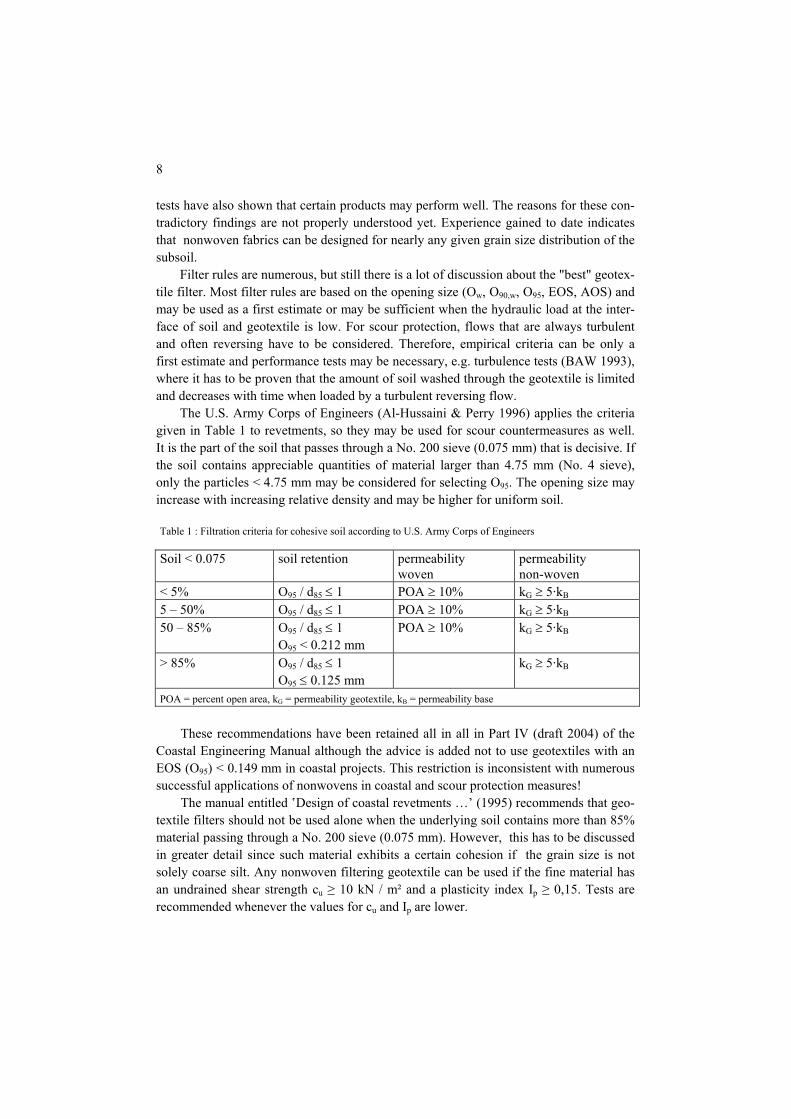
The U.S. Army Corps of Engineers (Al-Hussaini & Perry 1996) applies the criteria given in Table 1 to revetments, so they may be used for scour countermeasures as well. It is the part of the soil that passes through a No. 200 sieve (0.075 mm) that is decisive. If the soil contains appreciable quantities of material larger than 4.75 mm (No. 4 sieve), only the particles < 4.75 mm may be considered for selecting O95. The opening size may increase with increasing relative density and may be higher for uniform soil.
Table 1 : Filtration criteria for cohesive soil according to U.S. Army Corps of Engineers Soil < 0.075 soil retention permeability
woven permeability non-woven
< 5% O95 / d85 ≤ 1 POA ≥ 10% kG ≥ 5·kB 5 – 50% O95 / d85 ≤ 1 POA ≥ 10% kG ≥ 5·kB 50 – 85% O95 / d85 ≤ 1
O95 < 0.212 mm POA ≥ 10% kG ≥ 5·kB
> 85% O95 / d85 ≤ 1 O95 ≤ 0.125 mm
kG ≥ 5·kB
POA = percent open area, kG = permeability geotextile, kB = permeability base
These recommendations have been retained all in all in Part IV (draft 2004) of the
Coastal Engineering Manual although the advice is added not to use geotextiles with an EOS (O95) < 0.149 mm in coastal projects. This restriction is inconsistent with numerous successful applications of nonwovens in coastal and scour protection measures!
The manual entitled ‛Design of coastal revetments …’ (1995) recommends that geo-textile filters should not be used alone when the underlying soil contains more than 85% material passing through a No. 200 sieve (0.075 mm). However, this has to be discussed in greater detail since such material exhibits a certain cohesion if the grain size is not solely coarse silt. Any nonwoven filtering geotextile can be used if the fine material has an undrained shear strength cu ≥ 10 kN / m² and a plasticity index Ip ≥ 0,15. Tests are recommended whenever the values for cu and Ip are lower.

9
Similar to the proposal for granular filters, Lafleur et al. (1996) showed in numerous tests that the form of the grain size distribution also has to be taken into account when using geotextile filters (Fig.3).
Holtz et al. (1997) published basic criteria, which are summarized in Table 2, but proposed tests in critical or severe applications.
4 Hydraulic criteria for granular filters
Besides the above-mentioned geometrical criteria, other parameters affect the function of filters, e.g. the state of stress, the shear strength of filter and subsoil or dynamic loads. The hydraulic boundary conditions have to be checked if the grain size distributions of filter and subsoil do not fulfil the geometrical criteria. The maximum gradient is the gov-erning parameter that has to be considered in order to assess the reliability of a filter.
The critical hydraulic gradient is dependent on the direction of flow (vertical, up-ward or downward, horizontal) and the relative direction of the flow and the contact plane of filter and subsoil (parallel or perpendicular). It was also found that the critical gradient is inversely proportional to the size of the particles.
Another important parameter is the hydraulic conductivity. Both parameters, the hy-draulic conductivity and the hydraulic gradient, are very difficult to determine and usu-ally vary greatly so an approach to filter design based on hydraulic criteria can often only be a rough estimate.
gap graded concave upward linearly graded
base soil CU ≤ 6
internally stable
dI = d85 dI = d50 dI = dG1) dI = d30
2)
O95 ≤ dI
kF < 20 kB
dI < O95 ≤ 5 dI
Y
N
Y
N
1) dG = lower size of the gap
2) risk of piping of finer particles
Fig.3: Design chart (geotextile filter) according to Lafleur (1996)

10
Table 2: Geotextile Design and Selection Criteria for Hard Armour Erosion Control Applications
SOIL RETENTION (PIPING RESISTANCE CRITERIA) Soils Steady state flow Dynamic, pulsating, cyclic
flow (if geotextile can move) < 50% passing 0.075 mm (d50 < 0.075 mm)
AOS or O95 < B • d85 8 > CU < 2: B = 1 2 < CU < 4: B = 0.5 CU 4 < CU < 8: B = 8 / CU
O95 < 0.5 d85
> 50% passing 0.075 mm (d50 > 0.075 mm)
Woven: O95 < d85 Nonwoven: O95 < 1.8 d85
O95 < 0.5 d85
cohesive soils (lP > 7) O95 ≤ 0.3 mm PERMEABILITY / PERMITTIVITY CRITERIA Critical / severe applications kgeotextile ≥ 10 ksoil Less critical / less severe applica-tions (clean medium to coarse sands and gravels)
kgeotextile ≥ ksoil
Permittivity requirement ψ > 0.7 sec-1 ψ > 0.2 sec-1 ψ > 0.1 sec-1
for < 15% passing 0.075 mm (d85 < 0.075 mm) for 15 to 50% passing 0.075 mm (d85 ≥ 0.075 mm ≥ d50) for > 50 % passing 0.075 mm (d50 > 0.075 mm)
CLOGGING CRITERIA Critical / severe applications Perform soil-geotextile filtra-
tion tests before specification
Less critical / less severe applica-tions
Perform soil-geotextile filtra-tion tests, but alternative given below
Alternative for less critical / less severe applications CU > 3 CU ≤ 3
O95 > 3 d15 specify geotextile with maximum opening size pos-sible from retention criteria
soils with ≥ 5% passing 0.075 mm (d95 ≥ 0.075 mm) soils with < 5% passing 0.075 mm (d95 < 0.075 mm)
woven geotextiles (monofil.) POA ≥ 4% POA 10%
nonwoven geotextiles Porosity ≥ 50% Porosity ≥ 70%

11
Wörman (1989) derived from tests a criterion for the armour layer thickness S that does not need an additional filter between the base and the armour. In this design situa-tion, erosion of base material through the armour layer will take place at the mean flow velocity that occurs when the design stability condition of the armour is exceeded:
• S = 0.16 • D • N • (d85,F • d15,F / d85,B) D = (ρF - ρW) / (ρB - ρW); ρF, ρB, ρW: density of filter, base and water N = nF / (1-nF); nF = porosity of the filter
A comparable design approach was developed by Bakker et al. (1994) that, in a simpli-fied form, reads:
• d15,F / d50,B = 0.5 • R / d50,F R = hydraulic radius that is assumed to equal water depth
(For more details of the approach, the reader is referred to the publication.) A design chart developed by Klein Breteler for gradients perpendicular to the soil –
filter interface is given in PIANC (1992), in which the filter material (d15,F) is selected on the basis of the hydraulic gradient (i⊥), the base material (d50,B), the filter porosity (nF) and the slope angle (α). The chart is based on an average density of sand (2.65 t/m³) and a water viscosity of 1.2·10-6 m²/s (Fig.3).
Fig. 3: Interface stability in granular filters according to Klein Breteler (PIANC 1992)

12
5 Hydraulic criteria for geotextile filters
Hydraulic criteria for geotextile filters are few and not universally valid. On the basis of tests, Klein Breteler (2000) proposed a design chart for a base soil of uniform sand with 0.1 < d90 < 0.25 and a coefficient of uniformity CU < 2 (Fig. 4).
6 Placement problems
The correct placement of a filter is as important as its design. Placing a geosynthetic filter cloth may be difficult because of the depth of the water, the current or the wave action. Placing a granular filter is difficult due to the fact that the first filter layer often consists of small sized grains, so the material may be eroded nearly as easily as the subsoil.
The traditional type of bottom protection used in coastal protection works to over-come these difficulties is the fascine mattress. This method is still often used today. In
Fig. 4: Design diagram by Klein Breteler for geometrically open geotextiles (only valid for geotextiles on non-cohesive, rather uniform sand with 0,1 < d90 < 0,25 mm and CU < 2) (Pilarczyk & Klein Breteler 2000)

13
most cases, a woven geotextile is chosen as a filter, fascines are tied onto it and the mat-tress is towed to its destination where it is sunk by dumping stones on it.
Using fascine mattresses is uneconomical if only small areas have to be protected. An alternative for mild currents is what is known as the "sandmat", i.e. a sand fill up to 9 kg/m² confined between two geosynthetic layers. The two layers are sewn or needle-punched to keep the sand in place. Stability can be achieved up to a flow velocity of approx. 1 m/s.
Granular filters are usually placed by dumping them in the water. However, only very narrowly graded material can be used. When a broadly graded filter material is dumped, the finer fraction takes longer to reach the bottom than the coarser fraction, causing material segregation. Thus a 'reverse filter' will be created in which the finer material is on top and the coarse layer below and which is therefore unable to retain the base soil. If a narrowly graded material is used, a larger number of layers with increasing grain diameter is needed to create a graded filter. This would increase the cost signifi-cantly and would cause problems in areas where a specified water depth has to be main-tained.
To overcome such problems, elements are needed that combine filter capacity with a certain weight to prevent them being eroded. The protection system should also be able to adapt to any subsoil geometry (including existing scour holes) and should be flexible to enable it to follow further scouring, e. g. by acting as a "falling apron". Geosynthetic containers meet these requirements (Fig.5). Container fabrics are usually designed as filters. Alternatively, a granular filter can be safely installed in a geosynthetic casing. Even a widely graded granular filter may be used without segregation as it is confined in the container. If the geotextile acts as a casing only, it is very important for the fabric to be more permeable than the filter fill.
7 Design of geosynthetic containers for scour countermeasures
The size of geosynthetic containers has to be chosen according to the hydraulic require-ments and operational restrictions. From the hydraulic point of view geosynthetic con-tainers should be as large as possible, since the larger they are the less they will be dis-placed. An approach to determining the required container size is given in Pilarczyk (2000). Design proposals for container fabrics required to act as filters are given in para-graph 3.
To ensure safe placement, a high level of serviceability and sufficient long-term re-sistance, a container material that will resist all mechanical loads must be selected. There is usually a choice of wovens and nonwovens. The first have the advantage of high ten-sile strength, the second the advantage of high straining capacity. By allowing large de-formations, the nonwoven fabric may be able to withstand impact loads more easily when the container hits the ground and when the stones are dumped on it. A minimum mass per unit area of 500 g/m² and a minimum tensile strength of 25 kN/m are recom-mended for nonwoven fabrics; the strain at rupture should exceed 50%. Nonwoven geo-

14
textile containers may even be used to cover quite steep slopes due to the high friction angle and as it is possible to construct a steep protection layer by stacking the containers. Additional stability may be gained by connecting the containers using Velcro.
If containers have to sustain abrasive forces due to rocking armourstones or due to bedload transport, any geosynthetic material used in their construction will need to be highly resistant to abrasion. This can only be proven by conducting the appropriate tests (BAW 1993).
The amount of fill should not exceed 80% of the theoretical volume to ensure good adjustment to the subsoil, structures or adjacent geocontainers. However, such filter layers must be protected by an armour layer since hydrodynamic loads may cause any loose parts of the container to flap, leading to wear or fatigue failure. Geotextile contain-ers without protection may be used when the hydraulic load is low or when they are filled completely, but, if this is the case, great care must be taken to ensure that no voids remain in between the containers.
8 Conclusion
Reliable permeable scour protection needs a well-designed filter. For the subsoil-filter interface there are reliable criteria available, but one has to check the limits of applica-tion. Looking at the (granular) filter-armour interface, there are only few criteria that can
Fig. 5: Bank protection using geotextile containers (Bangladesh, courtesy K. Oberhagemann)

15
be used. This is due to the hydrodynamic loads acting on such structures and the large grain sizes that are often required for the top layer.
Filter rules based on geometrical criteria are well established. Some approaches can also be applied successfully to material that is coarser than gravel, e.g. the approaches of the U.S. Corps of Engineers (1995), Cistin/Ziems and the additional recommendations of Myogahara (1993). Criteria based on the weight of the armour material, such as those given in the Coastal Engineering Manual, call for very narrow spacing of filter and base. Hydraulic criteria should be used with caution, since the necessary parameters – hydrau-lic gradient and/or hydraulic conductivity – are difficult to determine or the assumptions made in the approach may not suit the actual site. The advantage of geotextile filters is that they can be used irrespective of the void size of the armour. Tests are recommended for geotextile filters in severe applications (e.g. BAW 1993). For a good estimate, the filter rules of Holtz et al. (1997) or Lafleur (1996) can be applied.
During the construction of scour countermeasures, the placement of the filter layer may be hampered by strong currents or waves. Placing geotextile containers as a filter layer constitutes an almost universally applicable method. The size of such containers must be selected such that individual elements will not be dislodged and the fabric must be designed carefully with respect to filtration and robustness.
References
Al-Hussaini, M.M.; Perry, E.B.: Corps of Engineers guide specification for use of geotextiles as filters. In: Lafleur, J; Rollin, A.L. (Eds.): Geofilters'96 – Proceedings. Montreal: Ecole Poly-technique 1996, pp. 11-19
Baker, K.J.; Verheij, H.J.; de Groot, M.B.:Design relationship for filters in bed protection. In: Journal of Hydraulic engineering, Vol 120, Sep 1994, pp.1082-1088
BAW - Federal Waterways Engineering and Research Institute: Code of Practice "Use of Geotex-tile Filters on Waterways (MAG)". BAW, Karlsruhe, Germany, 1993.
BAW - Federal Waterways Engineering and Research Institute: Code of Practice "Use of Granular Filters on Waterways (MAK)" – in German only. BAW, Karlsruhe, Germany, 1989.
Bertram, G.E.: An experimental investigation of protective filters. Graduate School of Engineering, Harvard University Cambridge Mass. Pub. 267, Series 7.
Busch, K.-F.; Luckner, L.: Geohydraulik. Stuttgart. Enke 1974 Cistin, J.: Konstrukce a stavba filtru syspanych hrazi. VVHU Brno 1968 HEC-11: Hydraulic Engineering Circular No. 11 "DESIGN OF RIPRAP REVETMENT", McLean,
VA, USA: Federal Highway Administration 1989 Holtz, R.D.; Christopher, B.R.; Berg, R.R.: Geosynthetic Engineering. Richmond: BiTech Publish-
ers Ltd. 1997 Honjo, Y.; Veneziano, D.: Improved filter criterion for cohesionless soils. ASCE Journal of Geo-
technical Engineering 1989, Vol. 115, No.1, pp. 75-94 Klein Breteler, M.; Pilarczyk, K.: Geotextiles in revetment structures – A Dutch approach. In:
Wolski, W.; Mlynarek, J. (Eds.): Filters and Drainage in Geotechnical and Environmental En-gineering – Geofilters 2000 – Proceedings. Rotterdam: Balkema 2000, pp. 339-348

16
Köhler, H.-J. 1993: The influence of hydraulic head and hydraulic gradient on the filtration proc-ess. In: Brauns, J.; Heibaum, M.; Schuler, U. (Eds.): Filters in Geotechnical and Hydraulic En-gineering - Geofilters'92 – Proceedings. Rotterdam: Balkema 1993, pp. 225-240
Lafleur, J.; Mlynarek, J.; Rollin, A.L.: Filter criteria for well graded cohesionless soils. In: Brauns, J.; Heibaum, M.; Schuler, U. (Eds.): Filters in Geotechnical and Hydraulic Engineering - Geofilters'92 – Proceedings. Rotterdam: Balkema 1993, pp. 97-106
Lafleur, J.; Eichenauer, T.; Werner, G.: Geotextile filter retention criteria for well graded cohe-sionless soils. In: Lafleur, J; Rollin, A.L. (Eds.): Geofilters'96 – Proceedings. Montreal: Ecole Polytechnique 1996, pp. 429-438
Locke, M.; Indaratna, B.N.: Erosion and filtration of cohesive soils. In: Wolski, W.; Mlynarek, J. (Eds.): Filters and Drainage in Geotechnical and Environmental Engineering – Geofilters 2000 – Proceedings. Rotterdam: Balkema 2000, pp. 175-182
Myogahara, Y.; Morita, S.; Kuroki, H.: Piping stability in the filter material of rock-fill dams. In: Brauns, J.; Heibaum, M.; Schuler, U. (Eds.): Filters in Geotechnical and Hydraulic Engineering - Geofilters'92 – Proceedings. Rotterdam: Balkema 1993, pp. 107-111
PIANC Permanent international association of navigation congress): Guidelines for the design and construction of flexible revetments incorporating geotextiles in marine environment. Supple-ment to bulletins No 78/79. Brussels: PIANC 1992, pp122-124
Pilarczyk, K.: Geosynthetics and Geosystems in Hydraulic and Coastal Engineering. Rotterdam: Balkema 2000
Prinz, E.: Handbuch der Hydrologie. Berlin: Springer 1923 Schuler, U.: Bemessung von Erdstofffiltern unter besonderer Berücksichtigung der Parameter-
streuung. Veröffentlichungen des Instituts für Bodenmechanik und Felsmechanik der Universi-tät Fredericiana, Heft 143, Karlsruhe 1997
Sherard, J.; Dunnigan, L.; Talbot, R.: Filters for silts and clays. In: ASCE Journal of Geotechnical Engineering. Vol. 110 /6 (1984), pp. 701-718
Sichard, W.: Kies- und Sandfilter im Grund- und Wasserbau. Die Bautechnik 1952, Vol. 29, No. 3, S. 72-76
Terzaghi, K.; Peck, R.: Soil mechanics in engineering practice. New York: Wiley & Sons 1948 U.S. Department of the Interior - Bureau of Reclamation: Design of small dams, 1977 (2nd ed.) U.S. Department of the Interior - Bureau of Reclamation: Earth Manual. Denver 1960 (1st ed.),
1974 (2nd ed.), 1998 (3rd ed.) U.S. Army Corps of Engineers, Waterways Experiment Station: Filter experiments and design
criteria. Techn. Memo. Vicksburg 1953 U.S. Army Corps of Engineers Manual No. 1110-2-1614 Design of coastal revetments, seawalls
and bulkheads. Washington 1995 U.S. Army Corps of Engineers Coastal Engineering Manual part VI (draft), Washington 2003 Witt, K.-J. Filtrationsverhalten und Bemessung von Erdstoffiltern. Veröffentlichungen des Instituts
für Bodenmechanik und Felsmechanik der Universität Fredericiana, Heft 104, Karlsruhe 1986 Wittmann, L.: Filtrations- und Transportphänomene in porösen Medien. Veröffentlichungen des
Instituts für Bodenmechanik und Felsmechanik der Universität, Heft 86, Karlsruhe 1980 Wörmann, A.: Riprap protection without filter layers. In: Journal of Hydraulic engineering, Vol
115, Dec 1989, pp.1615-1630 Ziems, J.: Ein Beitrag zur Kontakterosion nichtbindiger Erdstoffe. Dissertation TU Dresden, 1968 U.S. Army Corps of Engineers: Investigation of Filter Requirements for Underdrains, Waterways
Experiment Station, Tech. Memo No. 183-1, Vicksburg, Miss., December 1941.