Hardware and measurement Abstraction l ayers · Hardware and measurement Abstraction l ayers

GEOTECHNICAL ENGINEERING REPORT Farmer’s Market Pavilion Chelsea Road and 14th Street West Point, Virginia
Schnabel Reference 19C33017 May 8, 2019 Prepared For:

May 8, 2019 Mr. John Edwards Town of West Point 321 6th Street West Point, VA 23181
Subject: Project 19C33017, Geotechnical Engineering Report Farmer’s Market Pavilion, Chelsea Road and 14th Street, West Point, Virginia
Dear Mr. Edwards: SCHNABEL ENGINEERING, LLC (Schnabel) is pleased to submit our geotechnical engineering report for this project. This study was performed in accordance with our proposal dated February 15, 2019, as authorized by you on February 20, 2019.
PROJECT DESCRIPTION
Site Description
The site is located at the northwest corner of the intersection of Chelsea Road and 14th Street. The site is relatively low lying and has been filled in the past. West Point Creek provides its western boundary. The site is generally grass covered with some scrub trees and bushes. There is a slight crown near the southeast corner of the site. The site slopes down to the north and west towards the marsh and West Point Creek. We obtained the site information from our previous Preliminary Geotechnical Study dated August 8, 2008 and the site plans by Bay Design Group dated December 21, 2018, and through our site reconnaissance. A Site Vicinity Map is included as Figure 1.
Proposed Construction
The project consists of low impact development of the current Farmers Market site into a passive park. The park will include some concrete sidewalks, a mulch covered trail, a 49 space parking lot, and a 40 ft by 60 ft picnic pavilion. The parking lot will be constructed using a Tuff Track grass paver system. This study has explored the foundation and frame options for the proposed pavilion. The project details were garnered from our review of the project plans by Bay Design Group, dated December 21, 2018, and our discussion with you.

Town of West Point Farmer’s Market Pavilion
May 8, 2019 Page 2 Schnabel Engineering, LLC Project 19C33017 ©2019 All Rights Reserved
SUBSURFACE EXPLORATION AND LABORATORY TESTING PROGRAM
We performed a subsurface exploration and field testing program to identify the subsurface stratigraphy underlying the site and to evaluate the geotechnical properties of the materials encountered. This program included test borings. Exploration methods used are discussed below. The appendices contain the results of our exploration.
Subsurface Exploration Methods
Test Borings
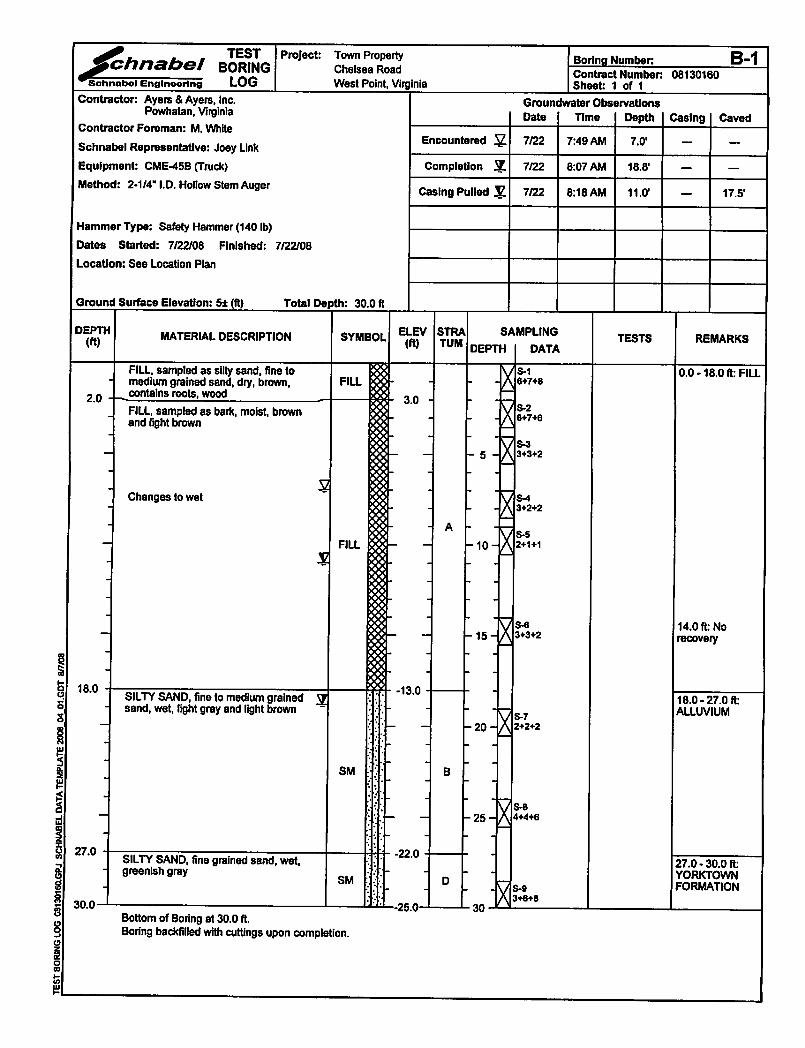
We observed our subcontractor, Ayers and Ayers, Inc., drill four test borings for this project on March 11, 2019. Ayers and Ayers also drilled four borings for a preliminary geotechnical evaluation we performed on this site in 2008 (Schnabel Project 08130160). Logs from those borings were referenced for this study and are included in the attachment. The Standard Penetration Test (SPT) was performed at selected depths in the borings. Appendix A includes specific observations, remarks, and logs for the borings; classification criteria; drilling methods; and sampling protocols. Figure 2 included at the end of this report indicates the approximate test boring locations. We will retain soil samples up to 45 days beyond the issuance of this report, unless you request other disposition.
SITE GEOLOGY AND SUBSURFACE CONDITIONS
Site Geology
We reviewed existing geologic data and information in our files. Based on this review, the geologic stratigraphy consists of recent alluvium underlain by Pleistocene Age deposits of the Tabb Formation. These soils are underlain by Miocene age, marine deposited soils of the Yorktown Formation. The recent alluvial soils typically exhibit low strength and high compressibility. The soils of the Tabb Formation mostly consist of pebbly sand, silty sand, and sandy silt typically exhibiting moderate strength and compressibility. The soils of the Yorktown Formation typically consist of silty sands and silts. These soils are sensitive to disturbance but exhibit high strengths and low compressibility. The above stratigraphy is typical in the West Point area. However, in the immediate vicinity of the project site, some or all of the above strata have been eroded or excavated, and commonly have been replaced with fill.
Generalized Subsurface Stratigraphy
We characterized the following generalized subsurface stratigraphy based on the recent exploration and laboratory test data included in the appendices.
Topsoil (Ground Cover):
About 6 to 12 inches of topsoil and rootmat were encountered at each of the boring locations. The topsoil at the pavilion location was about 6 inches thick.

Town of West Point Farmer’s Market Pavilion
May 8, 2019 Page 3 Schnabel Engineering, LLC Project 19C33017 ©2019 All Rights Reserved
Strata A and B: Existing Fill
Existing fill soils and bark were encountered below the ground cover to depths of 14 to 19 ft at the pavilion location and to the maximum depth of penetration, 5 ft, in the borings performed in the proposed parking lot. The fill encountered near the ground surface at the pavilion location was generally sand and was firm to compact density to a depth of about 5 to 6 ft (Stratum A). That fill became very loose and was underlain by between about 6 and 10 ft of bark fill (Stratum B) to the depths referenced above.
Stratum C: Pleistocene Terrace
Below the fill soils of Strata A and B the borings encountered a riverine terrace deposit referenced as the Tabb Formation. These soils classified as clayey sand (SC), silty sand (SM), and poorly graded sand with silt (SP-SM) and were encountered to depths of 19 to 24 ft. Based on the Standard Penetration Tests performed, this stratum is generally very loose to firm to compact density: N = 2 to 12. Stratum D: Yorktown Formation The Miocene age marine deposits of the Yorktown Formation were encountered below Stratum C to the maximum depth of penetration, 35 ft. These soils classified as silty sand (SM) with varying amounts of shell fragments. The Yorktown Formation soils are the typical bearing stratum for structures supported on deep foundations.
Groundwater
We observed groundwater in the borings at depths of 19 to 30 ft. The borings caved dry at a depths of 5 ft. The test boring logs in Appendix A include groundwater observations obtained during our subsurface exploration. These data include depths to groundwater encountered during drilling, upon drilling completion, and following completion of the boring.
We did not obtain long-term water level readings since we backfilled the test borings upon completion for safety. The actual groundwater table on the site likely corresponds to the level of the tide in the adjacent Mattaponi River and West Point Creek.
Seismic Site Classification
We evaluated the Seismic Site Class and Seismic Site Coefficients for this project according to the International Building Code (IBC) Section 1615 (2015). Our analysis indicates Site Class E for this location. This Site Class was evaluated based on corrected SPT values.
GEOTECHNICAL RECOMMENDATIONS
We based our geotechnical engineering analysis on the information developed from our subsurface exploration and soil laboratory testing, along with the project development plans, site plans, and structural loading furnished to our office. We recommend supporting the pavilion on a structural slab founded on timber piles or helical piles. The following sections of the report provide our detailed recommendations.

Town of West Point Farmer’s Market Pavilion
May 8, 2019 Page 4 Schnabel Engineering, LLC Project 19C33017 ©2019 All Rights Reserved
Driven Piles
Pressure treated timber piles driven at least 4 ft into the Yorktown Formation soils of Stratum D are considered the most suitable driven pile foundation alternative. Based on the boring data we have estimated a pile tip elevation at El 75, when considering the temporary benchmark elevation shown on the Bay Design Plan. This equates to a pile length of 26 to 27 ft below the existing ground surface. We recommend ordering 30 ft long pressure treated timber piles with a nominal 12-inch butt diameter per ASTM D-25. The piles may be driven with a vibratory hammer assuming they can be installed to the minimum tip elevation defined above. Very dense fill is present to a depth of about 6 ft in the proposed pavilion location. It may be necessary to pre-auger the pile locations to a depth of about 10 ft to get through the dense fill layer. Piles driven at least 4 ft into the Yorktown Formation soils of Stratum D are estimated to have a design allowable capacity of 20 tons. Although the existing fill soils have been in place for several decades some down drag from possible additional settlement of the existing fill due to organic decay of the bark has been considered in the recommended pile capacity.
Piles driven to the above tip grades provide a factor of safety of at least 2.0 against vertical compressive load, based on static analyses. Provided a pile center-to-center spacing of at least three pile diameters is maintained, the capacity of a pile group will be equal to the individual pile capacity multiplied by the number of piles in the group. The capacity of a group with closer pile spacing will be less, and should be evaluated by the Geotechnical Engineer.
Pile settlement should be less than one inch under the allowable compressive load. Differential settlement between similarly loaded foundations is not expected to exceed about half this value.
Helical Piers
The proposed building on this site can also be supported on helical piers. The helical piers consist of galvanized steel shafts with one or more galvanized steel helices that develop capacity from the bearing capacity of the soil applied over the projected areas of the each individual helix. We submitted the available project data to a contractor that is licensed to install Chance Helical Piers. Chance is a trademark brand that provides design and installation for this foundation alternative. Based on their analyses, they recommend 10/12/14 lead helices transitioned to RS278.203 round pipe to provide a maximum compression/tension load of 49.5 kips or 5,500 ft-lbs of torque. A factor of safety of at least 2.0 was used in their design recommendations. The piers should be installed into the Yorktown Formation soils of Stratum D. The borings indicate existing fill and alluvial soils with high organic content on this site. Accordingly, corrosion protection will likely be required for helical piers.
Town of West Point Farmer’s Market Pavilion
May 8, 2019 Page 5 Schnabel Engineering, LLC Project 19C33017 ©2019 All Rights Reserved
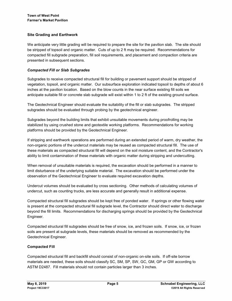
Site Grading and Earthwork
We anticipate very little grading will be required to prepare the site for the pavilion slab. The site should be stripped of topsoil and organic matter. Cuts of up to 2 ft may be required. Recommendations for compacted fill subgrade preparation, fill soil requirements, and placement and compaction criteria are presented in subsequent sections.
Compacted Fill or Slab Subgrades
Subgrades to receive compacted structural fill for building or pavement support should be stripped of vegetation, topsoil, and organic matter. Our subsurface exploration indicated topsoil to depths of about 6 inches at the pavilion location. Based on the blow counts in the near surface existing fill soils we anticipate suitable fill or concrete slab subgrade will exist within 1 to 2 ft of the existing ground surface.
The Geotechnical Engineer should evaluate the suitability of the fill or slab subgrades. The stripped subgrades should be evaluated through probing by the geotechnical engineer.
Subgrades beyond the building limits that exhibit unsuitable movements during proofrolling may be stabilized by using crushed stone and geotextile working platforms. Recommendations for working platforms should be provided by the Geotechnical Engineer.
If stripping and earthwork operations are performed during an extended period of warm, dry weather, the non-organic portions of the undercut materials may be reused as compacted structural fill. The use of these materials as compacted structural fill will depend on the soil moisture content, and the Contractor's ability to limit contamination of these materials with organic matter during stripping and undercutting.
When removal of unsuitable materials is required, the excavation should be performed in a manner to limit disturbance of the underlying suitable material. The excavation should be performed under the observation of the Geotechnical Engineer to evaluate required excavation depths.
Undercut volumes should be evaluated by cross sectioning. Other methods of calculating volumes of undercut, such as counting trucks, are less accurate and generally result in additional expense.
Compacted structural fill subgrades should be kept free of ponded water. If springs or other flowing water is present at the compacted structural fill subgrade level, the Contractor should direct water to discharge beyond the fill limits. Recommendations for discharging springs should be provided by the Geotechnical Engineer.
Compacted structural fill subgrades should be free of snow, ice, and frozen soils. If snow, ice, or frozen soils are present at subgrade levels, these materials should be removed as recommended by the Geotechnical Engineer.
Compacted Fill
Compacted structural fill and backfill should consist of non-organic on-site soils. If off-site borrow materials are needed, these soils should classify SC, SM, SP, SW, GC, GM, GP or GW according to ASTM D2487. Fill materials should not contain particles larger than 3 inches.

Town of West Point Farmer’s Market Pavilion
May 8, 2019 Page 6 Schnabel Engineering, LLC Project 19C33017 ©2019 All Rights Reserved
Compacted structural fill should be placed in maximum 8-inch thick horizontal, loose lifts. Fill should be compacted to at least 95 percent of the maximum dry density per ASTM D698 (Standard Proctor).
Backfill placed in excavations, trenches, and other areas that large compaction equipment cannot access should be placed in maximum 6-inch thick lifts. Backfill should meet the material, placement, and compaction requirements outlined above.
Successful re-use of the excavated, on-site soils as compacted structural fill will depend on their natural moisture contents during excavation. Scarifying and drying of these soils may be necessary to achieve the recommended compaction. Drying of these soils will likely result in some delays, and may not be possible during cooler, wetter weather. We recommend that the earthwork be performed during the warmer, drier times of the year.
Floor Slabs
The proposed floor slab will be pile supported. Other, non-load bearing hardscape should be supported on suitable existing fill soils of Stratum A, or compacted structural fill. A modulus of subgrade reaction, k, of 150 pci should be used in the design. The recommended modulus value is for a 1-ft-square plate. Some slab design software may consider different definitions of k for input. The Structural Engineer should contact our office if their software considers a different definition of k.
CONSTRUCTION CONSIDERATIONS
Site Grading and Earthwork
The test boring data indicate the approximate depth of topsoil based on our visual identification procedures. The depth of stripping needed to provide a suitable base for placement of earthwork or pavements may include topsoil and other softer surficial layers. Stripping depths in previously disturbed areas will be greater, particularly during periods of wet weather. The depth of required stripping should be determined by the excavation Contractor prior to construction using test pits, probes, or other means. Based on the test boring data the existing fill soils encountered in the area of the proposed pavilion appear relatively dense and should provide a stable platform for placement of new fill and for excavation and construction of the structural slab. However, these soils will likely become disturbed during installation of the pile foundations. Therefore, project planning should consider that some rehabilitation (excavation and replacement with new fill) may be required prior to forming and pouring the structural slab. Borings performed in the area of the proposed parking lot indicate much greater variability in the composition, density and consistency of the existing fill materials encountered near the ground surface. Bark fill was encountered just below the topsoil in the boring performed near the west end of that lot. Project planning should consider that some undercut and replacement will be required to grade the parking lot for placement of the TruGrid paving system. It may be necessary to “bridge” some of these unsuitable existing fill soils with layers of geotextile fabrics and crushed stone. Specific recommendations for bridging techniques can be provided during construction.

Town of West Point Farmer’s Market Pavilion
May 8, 2019 Page 7 Schnabel Engineering, LLC Project 19C33017 ©2019 All Rights Reserved
Traffic on stripped or undercut subgrades should be limited to reduce disturbance of underlying soils. Also, using lightweight, track-mounted dozer equipment for stripping will limit the disturbance of underlying soils, and may reduce the undercut volume needed. The Contractor should provide site drainage to maintain subgrades free of water and to avoid saturation and disturbance of the subgrade soils before placing compacted structural fill or pavement base course. This site drainage will be important during all phases of the construction work. The Contractor should be responsible for reworking of subgrades and compacted structural fill that were initially considered suitable but were later disturbed by equipment and/or weather.
Engineering Services During Construction
The engineering recommendations provided in this report are based on the information obtained from the subsurface exploration and laboratory testing. However, conditions on the site may vary between the discrete locations observed at the time of our subsurface exploration. The nature and extent of variations between borings may not become evident until during construction. To account for this variability, we should provide professional observation and testing of subsurface conditions revealed during construction as an extension of our engineering services. These services will also help in evaluating the contractor's conformance with the plans and specifications in accordance with building code requirements. Because of our unique position to understand the intent of the geotechnical engineering recommendations, retaining Schnabel for these services will allow the owner to receive consistent service throughout the project construction.
General Specification Recommendations
An allowance should be established to account for possible additional costs that may be required to construct earthwork and foundations as recommended in this report. Additional costs may be incurred for a variety of reasons including variation of soil between borings, greater than anticipated unsuitable soils, need for borrow fill material, wet on-site soils, obstructions, temporary dewatering, etc. The project specifications should indicate the Contractor's responsibility for providing adequate site drainage during construction. Inadequate drainage will most likely lead to disturbance of soils by construction traffic and increased volume of undercut. This report may be made available to prospective bidders for informational purposes. We recommend that the project specifications contain the following statement:
Schnabel Engineering, LLC has prepared this geotechnical engineering report for this project. This report is for informational purposes only and is not part of the contract documents. The opinions expressed represent the Geotechnical Engineer’s interpretation of the subsurface conditions, tests, and the results of analyses performed. Should the data contained in this report not be adequate for the Contractor's purposes, the Contractor may make, before bidding, independent exploration, tests and analyses. This report may be examined by bidders at the office of the Owner, or copies may be obtained from the Owner at nominal charge.

Town of West Point Farmer’s Market Pavilion
May 8, 2019 Page 8 Schnabel Engineering, LLC Project 19C33017 ©2019 All Rights Reserved
Additional data and reports prepared by others that could have an impact upon the Contractor's bid should also be made available to prospective bidders for informational purposes.
LIMITATIONS
We based the analyses and recommendations submitted in this report on the information revealed by our exploration. We attempted to provide for normal contingencies, but the possibility remains that unexpected conditions may be encountered during construction. This report has been prepared to aid in the evaluation of this site and to assist in the design of the project. It is intended for use concerning this specific project. We have endeavored to complete the services identified herein in a manner consistent with that level of care and skill ordinarily exercised by members of the profession currently practicing in the same locality and under similar conditions as this project. No other representation, express or implied, is included or intended, and no warranty or guarantee is included or intended in this report, or other instrument of service. We appreciate the opportunity to be of service for this project. Please call us if you have any questions regarding this report. Sincerely, SCHNABEL ENGINEERING, LLC Paul E Diggs, PE Principal Jeremy Mydlinski, PE Principal
PED:JLM:dah Figures Appendix A: Subsurface Exploration Data

May 8, 2019 Schnabel Engineering, LLC Project 19C33017 ©2019 All Rights Reserved
FIGURES
Figure 1: Site Vicinity Map Figure 2: Boring Location Plan

³5/8
/2019
This
Map
was
Crea
ted In
Schn
abel
Engin
eerin
gs Si
te Vic
inity
Map A
pplica
tion
NOT TO SCALE
arcgis
SITE VICINITYMAP
FIGURE 1
FARMER'S MARKET PAVILIONCHELSEA ROAD
WEST POINT, VIRGINIAPROJECT NO. 19C33017
Sources: Esri, HERE, Garmin, USGS, Intermap, INCREMENT P, NRCan, Esri Japan, METI, EsriChina (Hong Kong), Esri Korea, Esri (Thailand), NGCC, (c) OpenStreetMap contributors, and theGIS User CommunityEsri, HERE, Garmin, (c) OpenStreetMap contributors
_̂
© Schnabel Engineering, 2019. All Rights Reserved.

B-101
B-102
B-103
B-104
B-1
B-2
B-3
B-4/4A
2
LEGEND
APPROXIMATE BORING LOCATION
APPROXIMATE PREVIOUS BORING LOCATION (2008)
N
00 40' 80'
SCALE: 1"=40'
FARMER'S MARKET PAVILION
CHELSEA ROAD
WEST POINT, VIRGINIA
Base Plan Provided by Bay Design Group on February 27, 2019.
BORING LOCATION PLAN
19C33017
E. BRADSHAW
P. DIGGS MAY 2019
Figure Name:
Project Number:
Done:
Reviewed:
Figure Number:
Date:
G:\2
01
1 - 2
02
0\2
01
9\N
ew
po
rt N
ew
s\1
9C
33
01
7 F
arm
ers M
arke
t P
avillio
n\0
3-S
E P
ro
du
cts\0
8-C
AD
\E
JB
T
em
pla
te
.d
wg
, 5
/7
/2
01
9 1
2:3
0:0
0 P
M

May 8, 2019 Schnabel Engineering, LLC Project 19C33017 ©2019 All Rights Reserved
APPENDIX A
SUBSURFACE EXPLORATION DATA
Subsurface Exploration Procedures General Notes for Subsurface Exploration Logs Identification of Soil Boring Logs, B-101 through B-104 Previous Test Boring Logs, B-1 through B-4

May 8, 2019 Schnabel Engineering, LLC Project 19C33017 ©2019 All Rights Reserved
SUBSURFACE EXPLORATION PROCEDURES
Test Borings – Hollow Stem Augers
The borings are advanced by turning a continuous flight auger with a center opening of 2¼ or 3¼ inches. A plug device blocks off the center opening while augers are advanced. Cuttings are brought to the surface by the auger flights. Sampling is performed through the center opening in the hollow stem auger, by standard methods, after removal of the plug. Usually, no water is introduced into the boring using this procedure.
Standard Penetration Test Results
The numbers in the Sampling Data column of the boring logs represent Standard Penetration Test (SPT) results. Each number represents the blows needed to drive a 2-inch O.D., 1⅜-inch I.D. split-spoon sampler 6 inches, using a 140-pound hammer falling 30 inches. The sampler is typically driven a total of 18 or 24 inches. The first 6 inches are considered a seating interval. The total of the number of blows for the second and third 6-inch intervals is the SPT “N value.” The SPT is performed according to ASTM D1586.
Soil Classification Criteria
The group symbols on the logs represent the Unified Soil Classification System Group Symbols (ASTM D2487) based on visual observation and limited laboratory testing of the samples. Criteria for visual identification of soil samples are included in this appendix. Some variation can be expected between samples visually classified and samples classified in the laboratory.
Boring Locations and Elevations
Borings locations were located using sub-meter GPS equipment. Approximate boring locations are shown on Figure 2. Ground surface elevations at the boring locations were obtained from the site topographic plan prepared by Bay Design. This topographic plan used a temporary benchmark reference of El 100.0. The scaled elevations are indicated on the boring logs. Locations and elevations should be considered no more accurate than the methods used to determine them.

May 8, 2019 Schnabel Engineering, LLC Project 19C33017 ©2019 All Rights Reserved
GENERAL NOTES FOR SUBSURFACE EXPLORATION LOGS
1. Numbers in sampling data column next to Standard Penetration Test (SPT) symbols indicate
blows required to drive a 2-inch O.D., 1⅜-inch I.D. sampling spoon 6 inches using a 140 pound hammer falling 30 inches. The Standard Penetration Test (SPT) N value is the number of blows required to drive the sampler 12 inches, after a 6 inch seating interval. The Standard Penetration Test is performed in general accordance with ASTM D1586.
2. Visual classification of soil is in accordance with terminology set forth in “Identification of Soil.” The ASTM D2487 group symbols (e.g., CL) shown in the classification column are based on visual observations.
3. Estimated water levels indicated on the logs are only estimates from available data and may vary with precipitation, porosity of the soil, site topography, and other factors.
4. Refusal at the surface of rock, boulder, or other obstruction is defined as an SPT resistance of 50 blows for 1 inch or less of penetration.
5. The logs and related information depict subsurface conditions only at the specific locations and at the particular time when drilled or excavated. Soil conditions at other locations may differ from conditions occurring at these locations. Also, the passage of time may result in a change in the subsurface soil and water level conditions at the subsurface exploration location.
6. The stratification lines represent the approximate boundary between soil and rock types as obtained from the subsurface exploration. Some variation may also be expected vertically between samples taken. The soil profile, water level observations and penetration resistances presented on these logs have been made with reasonable care and accuracy and must be considered only an approximate representation of subsurface conditions to be encountered at the particular location.
7. Key to symbols and abbreviations:
S-1, SPT Sample No., Standard Penetration Test 5+10+1 Number of blows in each 6-inch increment
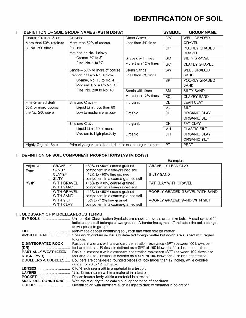
IDENTIFICATION OF SOIL I. DEFINITION OF SOIL GROUP NAMES (ASTM D2487) SYMBOL GROUP NAME
Coarse-Grained Soils More than 50% retained on No. 200 sieve
Gravels – More than 50% of coarse fraction retained on No. 4 sieve Coarse, ¾” to 3” Fine, No. 4 to ¾”
Clean Gravels Less than 5% fines
GW WELL GRADED GRAVEL
GP POORLY GRADED GRAVEL
Gravels with fines More than 12% fines
GM SILTY GRAVEL GC CLAYEY GRAVEL
Sands – 50% or more of coarse Fraction passes No. 4 sieve Coarse, No. 10 to No. 4 Medium, No. 40 to No. 10 Fine, No. 200 to No. 40
Clean Sands Less than 5% fines
SW WELL GRADED SAND
SP POORLY GRADED SAND
Sands with fines More than 12% fines
SM SILTY SAND SC CLAYEY SAND
Fine-Grained Soils 50% or more passes the No. 200 sieve
Silts and Clays – Liquid Limit less than 50 Low to medium plasticity
Inorganic CL LEAN CLAY ML SILT
Organic OL ORGANIC CLAY ORGANIC SILT
Silts and Clays – Liquid Limit 50 or more Medium to high plasticity
Inorganic CH FAT CLAY MH ELASTIC SILT
Organic OH ORGANIC CLAY ORGANIC SILT
Highly Organic Soils Primarily organic matter, dark in color and organic odor PT PEAT
II. DEFINITION OF SOIL COMPONENT PROPORTIONS (ASTM D2487) Examples
Adjective Form
GRAVELLY SANDY
>30% to <50% coarse grained component in a fine-grained soil
GRAVELLY LEAN CLAY
CLAYEY SILTY
>12% to <50% fine grained component in a coarse-grained soil
SILTY SAND
“With” WITH GRAVEL WITH SAND
>15% to <30% coarse grained component in a fine-grained soil
FAT CLAY WITH GRAVEL
WITH GRAVEL WITH SAND
>15% to <50% coarse grained component in a coarse-grained soil
POORLY GRADED GRAVEL WITH SAND
WITH SILT WITH CLAY
>5% to <12% fine grained component in a coarse-grained soil
POORLY GRADED SAND WITH SILT
III. GLOSSARY OF MISCELLANEOUS TERMS
SYMBOLS ............................ Unified Soil Classification Symbols are shown above as group symbols. A dual symbol “-“ indicates the soil belongs to two groups. A borderline symbol “/” indicates the soil belongs to two possible groups.
FILL ........................................ Man-made deposit containing soil, rock and often foreign matter. PROBABLE FILL................... Soils which contain no visually detected foreign matter but which are suspect with regard
to origin. DISINTEGRATED ROCK (DR) ........................................
Residual materials with a standard penetration resistance (SPT) between 60 blows per foot and refusal. Refusal is defined as a SPT of 100 blows for 2” or less penetration.
PARTIALLY WEATHERED ROCK (PWR) .........................
Residual materials with a standard penetration resistance (SPT) between 100 blows per foot and refusal. Refusal is defined as a SPT of 100 blows for 2” or less penetration.
BOULDERS & COBBLES ..... Boulders are considered rounded pieces of rock larger than 12 inches, while cobbles range from 3 to 12 inch size.
LENSES ................................. 0 to ½ inch seam within a material in a test pit. LAYERS ................................. ½ to 12 inch seam within a material in a test pit. POCKET ................................ Discontinuous body within a material in a test pit. MOISTURE CONDITIONS ..... Wet, moist or dry to indicate visual appearance of specimen. COLOR .................................. Overall color, with modifiers such as light to dark or variation in coloration.
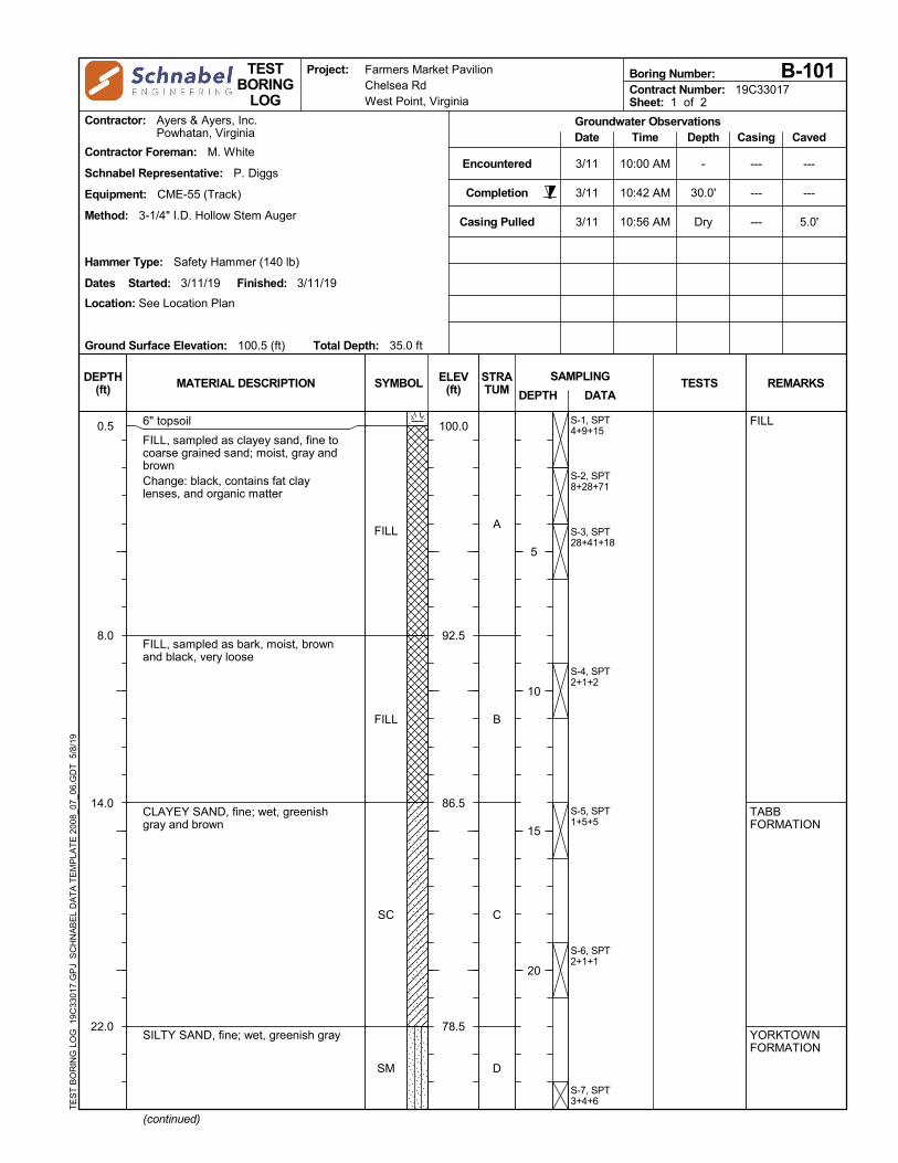
FILL
FILL
SC
SM
100.0
92.5
86.5
78.5
0.5
8.0
14.0
22.0
S-1, SPT4+9+15
S-2, SPT8+28+71
S-3, SPT28+41+18
S-4, SPT2+1+2
S-5, SPT1+5+5
S-6, SPT2+1+1
S-7, SPT3+4+6
6" topsoil
FILL, sampled as clayey sand, fine tocoarse grained sand; moist, gray andbrownChange: black, contains fat claylenses, and organic matter
FILL, sampled as bark, moist, brownand black, very loose
CLAYEY SAND, fine; wet, greenishgray and brown
SILTY SAND, fine; wet, greenish gray
FILL
TABBFORMATION
YORKTOWNFORMATION
A
B
C
D
Encountered
Completion
Casing Pulled
3/11
3/11
3/11
10:00 AM
10:42 AM
10:56 AM
-
30.0'
Dry
---
---
---
---
---
5.0'
Schnabel Representative: P. Diggs
Total Depth: 35.0 ft
Method: 3-1/4" I.D. Hollow Stem Auger
Equipment: CME-55 (Track)
Ground Surface Elevation: 100.5 (ft)
Contractor: Ayers & Ayers, Inc.Powhatan, Virginia
Contractor Foreman: M. White
Hammer Type: Safety Hammer (140 lb)
Dates Started: 3/11/19 Finished: 3/11/19
Location: See Location Plan
Date CavedDepthTime CasingGroundwater Observations
Farmers Market PavilionChelsea RdWest Point, Virginia
SYMBOL
Contract Number: 19C33017Sheet: 1 of 2
SAMPLING
DEPTH
5
10
15
20
DEPTH(ft)
ELEV(ft)
TESTBORING
LOG
Boring Number:
DATAMATERIAL DESCRIPTION
B-101
REMARKS
Project:
STRATUM TESTS
TE
ST
BO
RIN
G L
OG
19
C33
017.
GP
J S
CH
NA
BE
L D
AT
A T
EM
PLA
TE
200
8_07
_06
.GD
T
5/8/
19
(continued)
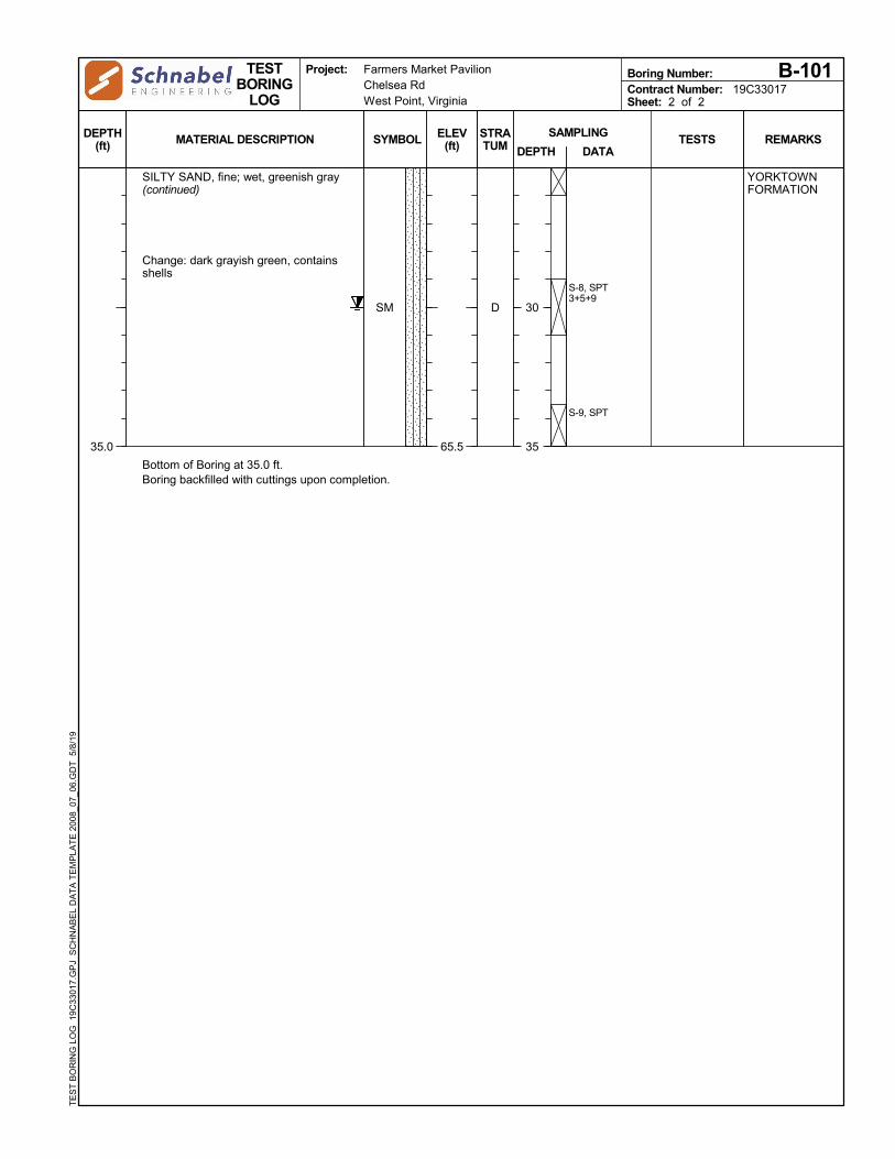
SM
65.535.0
S-8, SPT3+5+9
S-9, SPT
SILTY SAND, fine; wet, greenish gray(continued)
Change: dark grayish green, containsshells
YORKTOWNFORMATION
D
Bottom of Boring at 35.0 ft.Boring backfilled with cuttings upon completion.
Farmers Market PavilionChelsea RdWest Point, Virginia
SYMBOL
Contract Number: 19C33017Sheet: 2 of 2
SAMPLING
DEPTH
30
35
DEPTH(ft)
ELEV(ft)
TESTBORING
LOG
Boring Number:
DATAMATERIAL DESCRIPTION
B-101
REMARKS
Project:
STRATUM TESTS
TE
ST
BO
RIN
G L
OG
19
C33
017.
GP
J S
CH
NA
BE
L D
AT
A T
EM
PLA
TE
200
8_07
_06
.GD
T
5/8/
19

FILL
FILL
FILL
SP-SM
SM
101.5
100.0
88.0
83.0
78.0
0.5
2.0
14.0
19.0
24.0
S-1, SPT2+3+4
S-2, SPT3+8+11
S-3, SPT26+55+37
S-4, SPT3+2+2
S-5, SPT2+3+2
S-6, SPT3+4+5
S-7, SPT6+7+5
S-8, SPT7+4+5
6" topsoil
FILL, sampled as fat clay with sand;moist, gray and brown
FILL, sampled as clayey sand, fine tomedium grained sand; brownish greenand black, contains organics
Change: fine to coarse grained sand
Change: very loose
Change: contains bark
FILL, sampled as bark; moist, brownand black
POORLY GRADED SAND WITH SILT;wet, tan
SILTY SAND, fine; moist, greenishgray and brown
FILL
TABBFORMATION
YORKTOWNFORMATION
A
B
C
D
Encountered
Completion
Casing Pulled
3/11
3/11
3/11
9:12 AM
9:34 AM
9:49 AM
19.0'
Dry
Dry
---
---
---
---
---
5.0'
Schnabel Representative: P. Diggs
Total Depth: 35.0 ft
Method: 3-1/4" I.D. Hollow Stem Auger
Equipment: CME-55 (Track)
Ground Surface Elevation: 102.0 (ft)
Contractor: Ayers & Ayers, Inc.Powhatan, Virginia
Contractor Foreman: M. White
Hammer Type: Safety Hammer (140 lb)
Dates Started: 3/11/19 Finished: 3/11/19
Location: See Location Plan
Date CavedDepthTime CasingGroundwater Observations
Farmers Market PavilionChelsea RdWest Point, Virginia
SYMBOL
Contract Number: 19C33017Sheet: 1 of 2
SAMPLING
DEPTH
5
10
15
20
DEPTH(ft)
ELEV(ft)
TESTBORING
LOG
Boring Number:
DATAMATERIAL DESCRIPTION
B-102
REMARKS
Project:
STRATUM TESTS
TE
ST
BO
RIN
G L
OG
19
C33
017.
GP
J S
CH
NA
BE
L D
AT
A T
EM
PLA
TE
200
8_07
_06
.GD
T
5/8/
19
(continued)

SM
67.035.0
S-9, SPT5+6+7
S-10, SPT4+7+11
SILTY SAND, fine; moist, greenishgray and brown (continued)
Change: greenish gray
YORKTOWNFORMATION
D
Bottom of Boring at 35.0 ft.Boring backfilled with cuttings upon completion.
Farmers Market PavilionChelsea RdWest Point, Virginia
SYMBOL
Contract Number: 19C33017Sheet: 2 of 2
SAMPLING
DEPTH
30
35
DEPTH(ft)
ELEV(ft)
TESTBORING
LOG
Boring Number:
DATAMATERIAL DESCRIPTION
B-102
REMARKS
Project:
STRATUM TESTS
TE
ST
BO
RIN
G L
OG
19
C33
017.
GP
J S
CH
NA
BE
L D
AT
A T
EM
PLA
TE
200
8_07
_06
.GD
T
5/8/
19

FILL
FILL
FILL
99.3
98.0
97.0
95.0
0.8
2.0
3.0
5.0
S-1, SPT4+11+14
S-2, SPT8+6+32
S-3, SPT16+26+11
8" topsoil
FILL, sampled as clayey sand, fine tocoarse grained sand; moist, orangishbrown
FILL, sampled as bark; moist, black
FILL, sampled as clayey sand, fine tocoarse grained sand; moist, black
FILL
A
B
A
Bottom of Boring at 5.0 ft.Boring backfilled with cuttings upon completion.
Encountered
Completion
Casing Pulled
3/11
3/11
3/11
11:19 AM
11:30 AM
11:40 AM
Dry
Dry
Dry
---
---
---
---
---
3.0'
Schnabel Representative: P. Diggs
Total Depth: 5.0 ft
Method: 3-1/4" I.D. Hollow Stem Auger
Equipment: CME-55 (Track)
Ground Surface Elevation: 100.0 (ft)
Contractor: Ayers & Ayers, Inc.Powhatan, Virginia
Contractor Foreman: M. White
Hammer Type: Safety Hammer (140 lb)
Dates Started: 3/11/19 Finished: 3/11/19
Location: See Location Plan
Date CavedDepthTime CasingGroundwater Observations
Farmers Market PavilionChelsea RdWest Point, Virginia
SYMBOL
Contract Number: 19C33017Sheet: 1 of 1
SAMPLING
DEPTH
5
DEPTH(ft)
ELEV(ft)
TESTBORING
LOG
Boring Number:
DATAMATERIAL DESCRIPTION
B-103
REMARKS
Project:
STRATUM TESTS
TE
ST
BO
RIN
G L
OG
19
C33
017.
GP
J S
CH
NA
BE
L D
AT
A T
EM
PLA
TE
200
8_07
_06
.GD
T
5/8/
19

FILL
98.5
94.5
1.0
5.0
S-1, SPT3+3+3
S-2, SPT8+4+7
S-3, SPT4+3+4
12" rootmat and topsoil
FILL, sampled as sandy lean clay, fineto coarse grained sand; moist, black,contains bark
FILL
A
Bottom of Boring at 5.0 ft.Boring backfilled with cuttings upon completion.
Encountered
Completion
Casing Pulled
3/11
3/11
3/11
11:04 AM
11:12 AM
11:15 AM
-
-
Dry
---
---
3.0'
---
---
3.0'
Schnabel Representative: P. Diggs
Total Depth: 5.0 ft
Method: 3-1/4" I.D. Hollow Stem Auger
Equipment: CME-55 (Track)
Ground Surface Elevation: 99.5 (ft)
Contractor: Ayers & Ayers, Inc.Powhatan, Virginia
Contractor Foreman: M. White
Hammer Type: Safety Hammer (140 lb)
Dates Started: 3/11/19 Finished: 3/11/19
Location: See Location Plan
Date CavedDepthTime CasingGroundwater Observations
Farmers Market PavilionChelsea RdWest Point, Virginia
SYMBOL
Contract Number: 19C33017Sheet: 1 of 1
SAMPLING
DEPTH
5
DEPTH(ft)
ELEV(ft)
TESTBORING
LOG
Boring Number:
DATAMATERIAL DESCRIPTION
B-104
REMARKS
Project:
STRATUM TESTS
TE
ST
BO
RIN
G L
OG
19
C33
017.
GP
J S
CH
NA
BE
L D
AT
A T
EM
PLA
TE
200
8_07
_06
.GD
T
5/8/
19


![Ayers Presentation 051611 Final[1]](https://static.fdocuments.us/doc/165x107/546258afb1af9fba388b4de0/ayers-presentation-051611-final1.jpg)