geotechnical challenges in slope engineering of infrastructures

G&P Professional Sdn Bhd (www.gnpgroup.com.my)
GEOTECHNICAL ENGINEERING GEOTECHNICAL ENGINEERING CHALLENGES FOR HIGHWAY CHALLENGES FOR HIGHWAY
DESIGN AND CONSTRUCTION ON DESIGN AND CONSTRUCTION ON SOFT GROUNDSOFT GROUND
By Engr. Dr. Gue See Sew (P.Eng)Engr. Dr. Wong Shiao Yun (G.Eng )

CHALLENGES FOR CHALLENGES FOR GEOTECHNICAL ENGINEERS GEOTECHNICAL ENGINEERS
ON SOFT GROUNDON SOFT GROUND
Consolidation Settlement
Bearing Capacity and
Consolidation Settlement
FAILURE EVENT IN MALAYSIAFAILURE EVENT IN MALAYSIA
SABAH

FAILURE EVENT IN MALAYSIAFAILURE EVENT IN MALAYSIA
SIBU

FAILURE EVENT IN MALAYSIAFAILURE EVENT IN MALAYSIA

FAILURE EVENT IN MALAYSIAFAILURE EVENT IN MALAYSIA

FAILURE EVENT IN MALAYSIAFAILURE EVENT IN MALAYSIA

FAILURE EVENT IN SINGAPOREFAILURE EVENT IN SINGAPORE

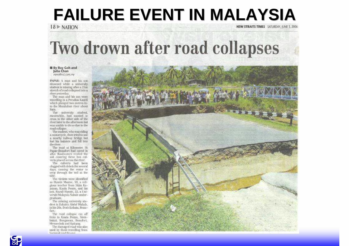
IDENTITY OF SOFT IDENTITY OF SOFT GROUNDGROUND
IDENTITY OF SOFT GROUNDIDENTITY OF SOFT GROUND
Su < 10kPa
Su > 10kPa

IDENTITY OF SOFT GROUNDIDENTITY OF SOFT GROUND

IDENTITY OF SOFT GROUNDIDENTITY OF SOFT GROUND
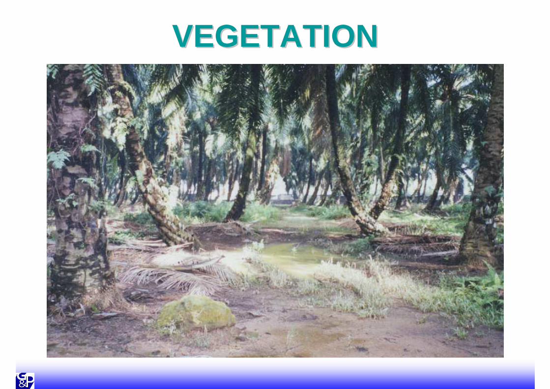
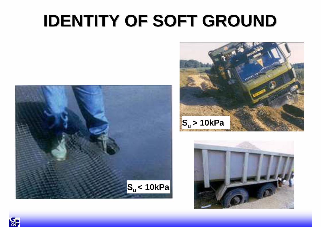
VEGETATIONVEGETATION

VEGETATIONVEGETATION

Alluvial Deposits
Soft Ground in Malaysia
Alluvial
Deposits
Embankment FailureEmbankment Failure

Embankment Treated with Vacuum Embankment Treated with Vacuum Preloading with Vertical DrainsPreloading with Vertical Drains
Very Loose Clayey SAND
Medium to Stiff Silty CLAY and Clayey SILT
Embankment Fill(Without Vacuum Preloading)
Embankment Fill (Failed Area)(Vacuum Preloading with Vertical Drains)
Vertical Drains
Liner and Sand Layerfor Vacuum System
Scale (m)
0 5 10
Soft Sandy CLAY
Very Soft Silty CLAY
(After Gue et al. 2001)
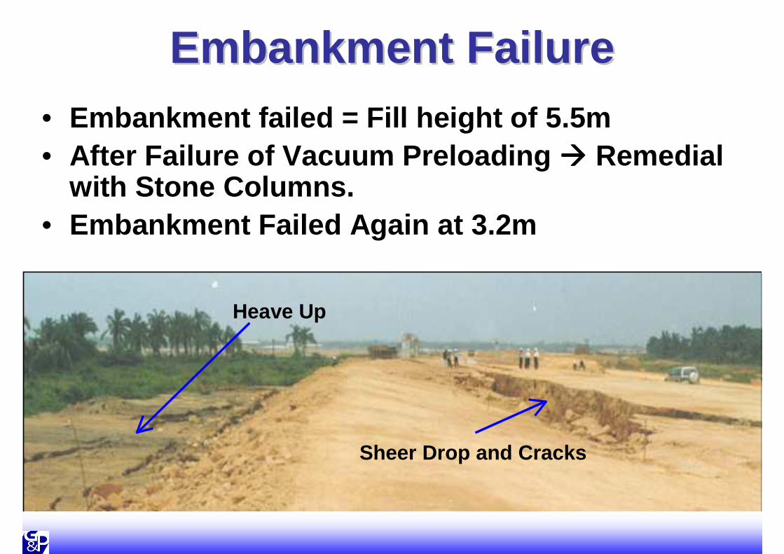
Embankment FailureEmbankment Failure• Embankment failed = Fill height of 5.5m• After Failure of Vacuum Preloading ���� Remedial
with Stone Columns.• Embankment Failed Again at 3.2m
Sheer Drop and Cracks
Heave Up

Undrained Shear Strength ProfileUndrained Shear Strength Profile
16
14
12
10
8
6
4
2
0D
epth
(m
)0 10 20 30
Sensitivity, St
Su-Undisturbed from VS-A
Su-Remolded from VS-A
Su-Undisturbed from VS-B
Su-Remolded from VS-B
In-Situ Vane Shear TestVS-A
VS-B
Su = 10 kPa
Su = 8 kPa
Su = 13 kPa
Su = 17 kPa
Su = 19 kPa
0 10 20 30 40 50 60Undrained Shear Strength, Su (kPa)

Monitored Pore Water PressuresMonitored Pore Water Pressures
Fist Crack Observed on Day 162
Excess Pore Water Pressure generated at PZ-A3, U = + ve
Excess Pore Water Pressure generated at PZ-A2, U = + ve
Stage BStage C
Stage D
Stage EStage F
∆
-2
0
2
4
6
8
10
12
Pie
zom
eter
Hea
d (
m)
Piezometers at Location Aat 3.0m depthat 6.0m depthat 8.0m depth
0 50 100 150 200 250 300 350Days0
2
4
6
Fill
Hei
gh
t (m
)
Designed Water Head is 3m at PZ-A1
Designed Water Headis 6m at PZ-A2.
Designed Water Headis 8m at PZ-A3 ∆
Figure 4 – Construction Sequence and

Failure of Embankment treated with Failure of Embankment treated with Stone ColumnsStone Columns
• Only Priebe’s Method was used
• Bulging & General Shear Failures not checked
• Independent review shows inadequate General Shear Capacity

Methods of Estimating Ultimate Methods of Estimating Ultimate Bearing CapacityBearing Capacity
• Large range of possible Ultimate Bearing Capacity• Attention when using stone columns in very soft
ground (e.g. su < 15kPa)

Lessons LearnedLessons Learned
• Vacuum Preloading Method shall be closely monitored
• Remedial design for failed embankment shall used “disturbed” soil strength
• Stone columns design shall check for all modes of failure+ Observational Method (recommended)
• Understand the Limitation of Software used ���� It may not check all the required modes of failures

Stone ColumnStone Column
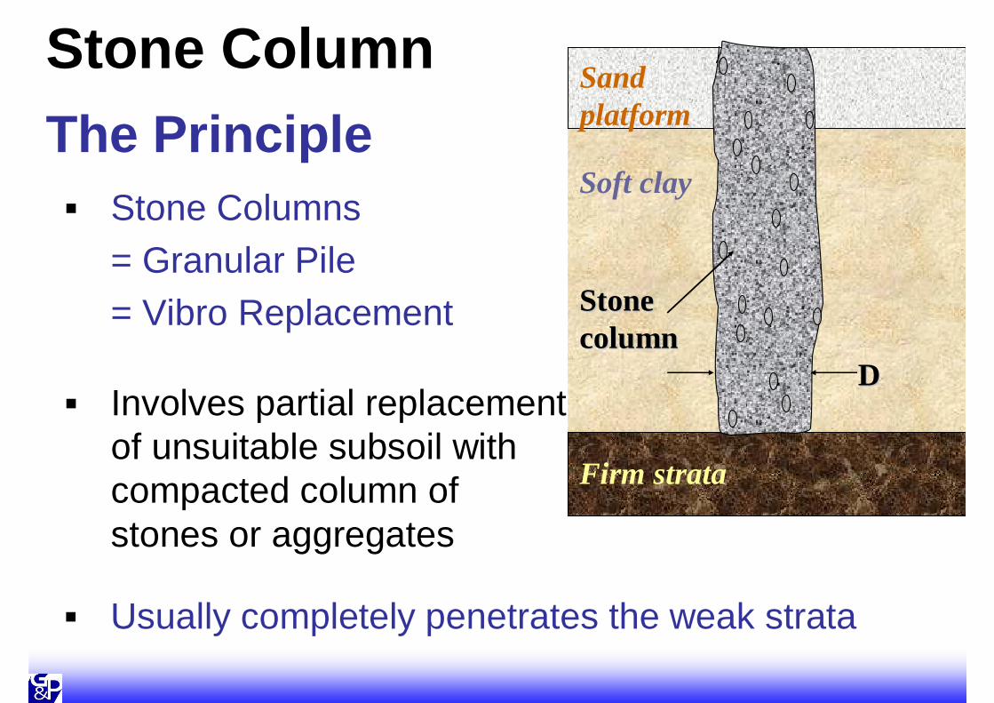
The Principle� Stone Columns
= Granular Pile = Vibro Replacement
� Involves partial replacement of unsuitable subsoil with compacted column of stones or aggregates
Stone Column
DD
Firm strata
Stone Stone columncolumn
Soft clay
Sand platform
� Usually completely penetrates the weak strata

Stone Column
`
EmbankmentSand Platform
Compressible Layer
Firm Strata

FunctionStone Column
� Provide bearing capacity / strengthening immediately upon installation
� Reduce settlement� Increase the rate of consolidation� Facilitate subsoil drainage
� Diameter: 0.6m - 1.2m

Other Available Option for Other Available Option for Ground ImprovementGround Improvement

SurchargingSurcharging• Temporarily compress the subsoil with
higher pressure than permanent load
• Achieve higher initial rate of settlement + reduce long term settlement
• Larger portion of fill left behind
• If fill material is available

Embankment
Soft SoilSoft Soil
Finished Level
SurchargingSurcharging
Surcharge

Fill
Thi
ckne
ss
Rest Period
Set
tlem
ent
Filling
Time
Time
With Surcharge
b a
FASTERFASTER
Without Surcharge
SurchargeSurcharge

Settlement
Settlement
Service Life of Service Life of
embankmentembankment
Permanent Permanent
LoadingLoading
Log Log
TimeTime
Log Log
TimeTime
Permanent Permanent
Loading OnlyLoading Only
Primary Primary
ConsolidationConsolidationSecondary Secondary
ConsolidationConsolidation
Permanent & Permanent &
Surcharge Surcharge
LoadingLoading
Service Service
Life Life
Settlement Settlement
without without
SurchargeSurcharge
Vertical Pressure from
Vertical Pressure from
Embankment Loading
Embankment Loading
Service Life of Service Life of
EmbankmentEmbankmentSurcharge Surcharge
DurationDurationConstructionConstruction

Temporary SurchargeTemporary Surcharge
Earthwork Surcharge in Progress

VERTICAL DRAINSVERTICAL DRAINS

FunctionsFunctions
• Provide shorterdrainage path
• Accelerate dissipation of excess pore water pressure


HD
Drainage Path for ConsolidationDrainage Path for Consolidation
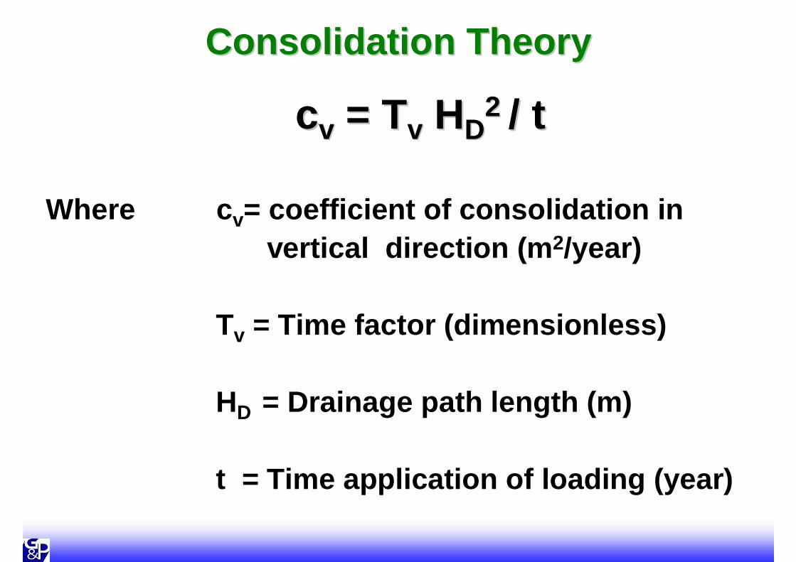
Consolidation TheoryConsolidation Theory
ccvv = T= Tvv HHDD2 2 / t/ t
Where c v= coefficient of consolidation in vertical direction (m 2/year)
Tv = Time factor (dimensionless)
HD = Drainage path length (m)
t = Time application of loading (year)

RearrangeRearrange ……
t = Tt = Tvv HHDD22 / / ccvv
ThereforeTherefore
100 100
times times
faster!faster!
1t 100
10m1mHD
t t ∝∝∝∝∝∝∝∝ HHDD22


INSTALLED PVDINSTALLED PVD

PVD INSTALLATION VIDEOPVD INSTALLATION VIDEO

Failure of Bridge Failure of Bridge Foundations and Approach Foundations and Approach
EmbankmentEmbankment

OverviewOverview
Abutment II
Pier II
Abutment I
Pier I

OverviewOverview
Abutment I Abutment II
Pier I
Pier II
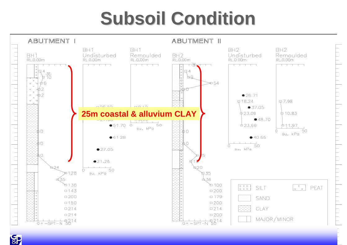
Subsoil ConditionSubsoil Condition
25m coastal & alluvium CLAY

Sheer DropSheer Drop
Sheer Drop
Pilecaps

Slip FailureSlip Failure

Tilted Abutment & Tilted Abutment & Gap between Bridge DecksGap between Bridge Decks
Opening between bridge
Tilt from Vertical

Pier IIPier II
Tilted Pilecap

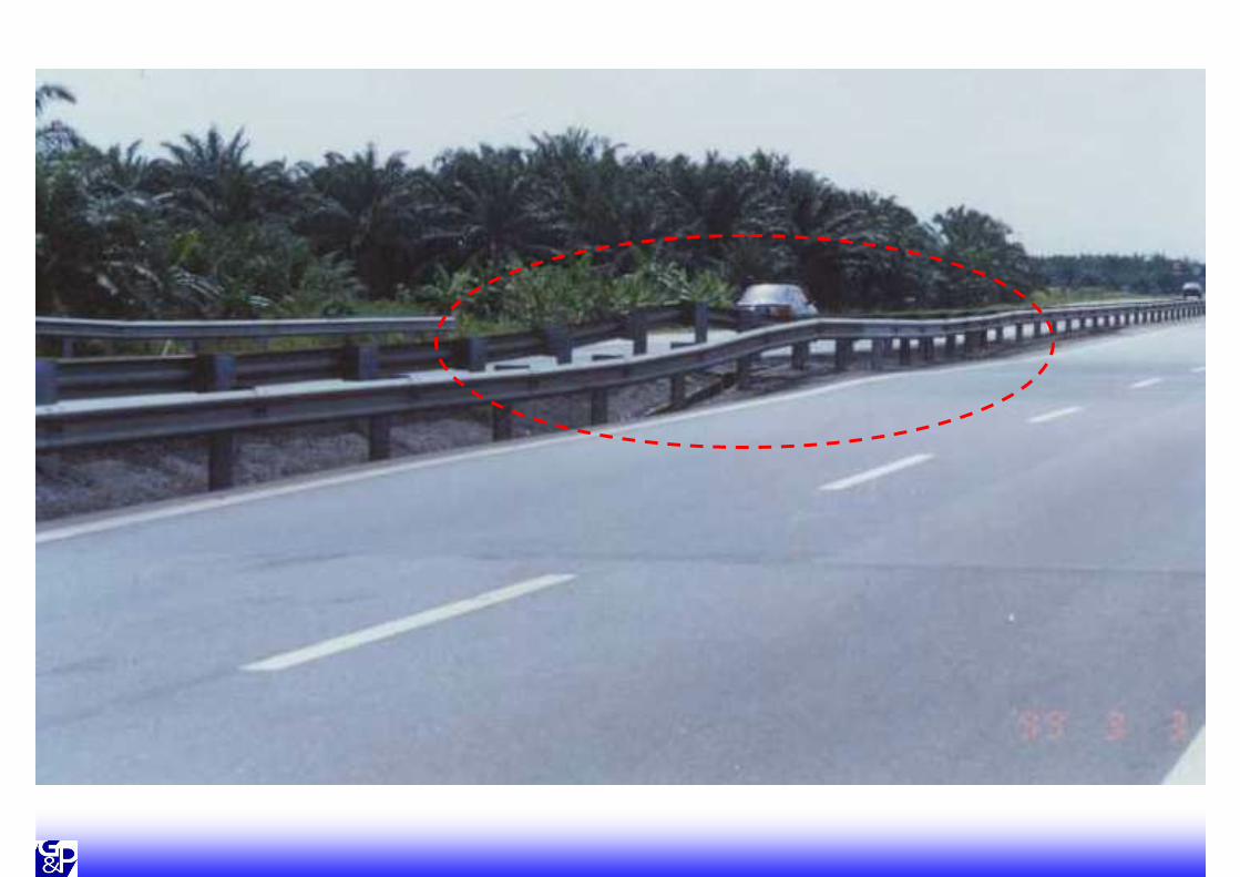
Slip Failure of EmbankmentSlip Failure of Embankment
• At 25m behind Abutment II
• Abutment II :- Tilted 550mm on top- Angular distortion of 1/6
• 300mm gap between bridge decks

Geotechnical InvestigationGeotechnical Investigation
• Hfailure @ 3m • HDesign @ 5.5m
���� NOT SAFE
HOW TO CHECK?

What Is The Critical Height?What Is The Critical Height?
HHfailurefailure = (= (NNcc x Su) / x Su) / γγγγγγγγfillfill
NNcc ≈≈≈≈≈≈≈≈ 55
HHfailurefailure = (5 x Su) / = (5 x Su) / γγγγγγγγfillfill
e.g. :e.g. :When When Su = 10 kPa ; Su = 10 kPa ; γγγγγγγγfillfill = 18 kN/m= 18 kN/m33
HHfailurefailure = (5 x 10)/ 18 = 2.8 m= (5 x 10)/ 18 = 2.8 m

• Failures ���� (temporary works)
- Inadequate geotechnicaldesign
- Subsoil Condition (Lack of understanding)
- Lack of constructioncontrol & supervision
Lessons LearnedLessons Learned

Preventive MeasuresPreventive Measures• Proper design and review
• Stability check of embankment & abutment
• Most critical :-During construction(must check temporary works)
• Proper full-time supervision(with relevant experience & understand design assumptions)

SETTLEMENT OF SETTLEMENT OF APPROACHES APPROACHES
BRIDGESBRIDGES


PilePilePilePile
O.G.L.O.G.L.O.G.L.O.G.L.
Final ProfileFinal ProfileFinal ProfileFinal Profile
Long Term Long Term Long Term Long Term ProfileProfileProfileProfile
AbutmentAbutmentAbutmentAbutment
Typical CrossTypical Cross --SectionSection

SOME SOLUTIONS TO SOME SOLUTIONS TO THE PROBLEMTHE PROBLEM

Expanded Polystyrene Expanded Polystyrene Expanded Polystyrene Expanded Polystyrene (EPS)(EPS)(EPS)(EPS)PilePilePilePile
AbutmentAbutmentAbutmentAbutment
O.G.L.O.G.L.O.G.L.O.G.L.
Final ProfileFinal ProfileFinal ProfileFinal Profile
Long Term Long Term Long Term Long Term ProfileProfileProfileProfile
USE OF LIGHT WEIGHT MATERIALUSE OF LIGHT WEIGHT MATERIAL
http://www.nhi.fhwa.dot.gov

USE OF TRANSITION EMBANKMENT PILESUSE OF TRANSITION EMBANKMENT PILES
Transition EmbankmentTransition EmbankmentTransition EmbankmentTransition EmbankmentPilesPilesPilesPiles
PilePilePilePile
AbutmentAbutmentAbutmentAbutment
O.G.L.O.G.L.O.G.L.O.G.L.
Final ProfileFinal ProfileFinal ProfileFinal Profile
Long Term Long Term Long Term Long Term ProfileProfileProfileProfile
Approach Approach Approach Approach SlabSlabSlabSlab

EXAMPLE (BERNAM JAYA)Transition Piles + Surcharging = Fewer Piles + Cost Saving


SETTLEMENT OF SETTLEMENT OF APPROACHES TO APPROACHES TO
CULVERTSCULVERTS

PILED CULVERTPILED CULVERT
Final Final Final Final ProfileProfileProfileProfile
PilePilePilePile
Long Term Long Term Long Term Long Term ProfileProfileProfileProfileO.G.L.O.G.L.O.G.L.O.G.L.

SOME SOLUTIONS TO SOME SOLUTIONS TO THE PROBLEMTHE PROBLEM

ENLARGED CULVERTENLARGED CULVERT
Final Final Final Final ProfileProfileProfileProfile
Long Term Long Term Long Term Long Term ProfileProfileProfileProfile
SiltSiltSiltSilt
O.G.L.O.G.L.O.G.L.O.G.L.
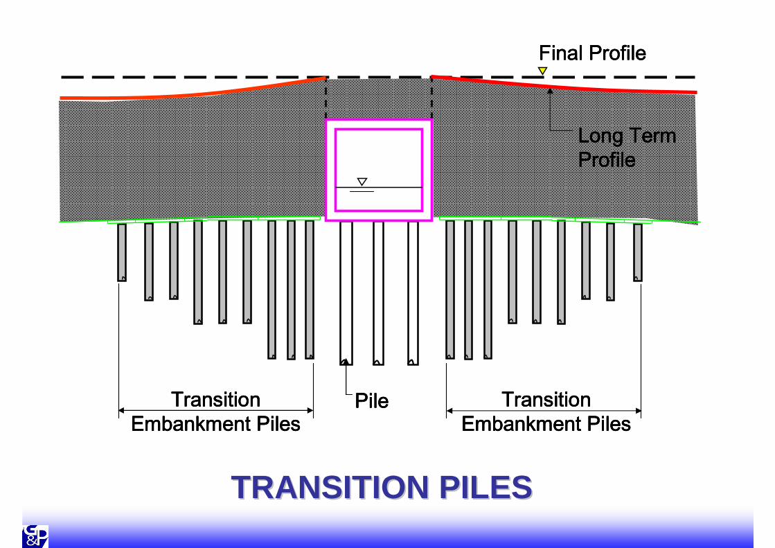
TRANSITION PILESTRANSITION PILES
PilePilePilePile
Final ProfileFinal ProfileFinal ProfileFinal Profile
Long Term Long Term Long Term Long Term ProfileProfileProfileProfile
Transition Transition Transition Transition Embankment PilesEmbankment PilesEmbankment PilesEmbankment Piles
Transition Transition Transition Transition Embankment PilesEmbankment PilesEmbankment PilesEmbankment Piles

Guidance Notes on Subsoil Guidance Notes on Subsoil InvestigationInvestigation

Guidance Notes on Subsoil InvestigationGuidance Notes on Subsoil Investigation
• Collect UD from BH
• Laboratory Test: UCT & 1-D Consolidation Test
• Piezocone : – To detect presence of sand lenses– qu
– Especially for surcharge design with or without PVD
LocalisedLocalised Weak ZoneWeak Zone

LocalisedLocalised Weak ZoneWeak Zone
• Generalisedmoderately conservative design line (MCL)

LocalisedLocalised Weak ZoneWeak Zone
• If not identifies, likely to cause failure
• Surcharge + PVD⇒⇒⇒⇒ Piled Embankment
• Further verify by Vane Shear Tests, Piezocones & MPs
ConclusionConclusion

CONCLUSIONCONCLUSION• Important:
Bearing Capacity assessment by CRUDE checkSYSTEMATIC check & review process(review by experienced engineers)STRUCTURED training programmes(enhance technical knowledge & share lessons learned)Full-time SUPERVISION with team of suitable experienceExtra Care on TEMPORARY WORKS
CONCLUSIONCONCLUSION
• DO NOT� Abuse geotechnical design , detailed
analysis
� Overlook localised weak zones
� Overlook structural detailing

SOFT GROUND CONSTRUCTION
G&P Geotechnics Sdn Bhd (www.gnpgroup.com.my)