Geotechnical Data Reportcontent.sabaltrailtransmission.com/resources/RR6_Sabal_Trail_APP-6... ·...
38
Geotechnical Data Report Sabal Trail Transmission Project Shingle Creek HDD Osceola County, Florida for Gulf Interstate Engineering November 17, 2014
Transcript of Geotechnical Data Reportcontent.sabaltrailtransmission.com/resources/RR6_Sabal_Trail_APP-6... ·...

Geotechnical Data Report
Sabal Trail Transmission Project Shingle Creek HDD Osceola County, Florida
for
Gulf Interstate Engineering
November 17, 2014

Geotechnical Data Report
Sabal Trail Transmission Project
Shingle Creek HDD
Osceola County, Florida
for
Gulf Interstate Engineering
November 17, 2014
3050 South Delaware Avenue
Springfield, Missouri 65804
417.831.9700
Geotechnical Data Report
Sabal Trail Transmission Project
Shingle Creek HDD
Osceola County, Florida
File No. 15347-006-00
November 17, 2014
Prepared for:
Gulf Interstate Engineering
16010 Barkers Point Lane, Suite 600
Houston, Texas 77079-9000
Attention: Denys Stavnychyi, Project Engineer
Prepared by:
GeoEngineers, Inc.
3050 South Delaware Avenue
Springfield, Missouri 65804
417.831.9700
Mark A. Miller, PE
Principal
David P. Sauls, PE
Senior Principal
JMP:MAM:DPS:kb
Disclaimer: Any electronic form, facsimile or hard copy of the original document (email, text, table, and/or figure), if provided, and any attachments are only a
copy of the original document. The original document is stored by GeoEngineers, Inc. and will serve as the official document of record.
Copyright© 2014 by GeoEngineers, Inc. All rights reserved.

November 17, 2014| Page i File No. 15347-006-00
Table of Contents
1.0 INTRODUCTION .................................................................................................................................... 1
2.0 SCOPE................................................................................................................................................... 1
3.0 SITE CONDITIONS ................................................................................................................................ 2
3.1 Geological Conditions ..................................................................................................................... 2
3.1.1 Regional Geologic Setting ..................................................................................................... 2
3.1.2. Site Geology .......................................................................................................................... 2
3.2 Subsurface Conditions .................................................................................................................... 3
3.2.1 General .................................................................................................................................. 3
3.2.2 Subsurface Description ........................................................................................................ 3
3.2.3 Groundwater Conditions ....................................................................................................... 4
3.3 Surface Conditions .......................................................................................................................... 4
3.3.1 General .................................................................................................................................. 4
3.3.2 Surface Description .............................................................................................................. 4
4.0 LIMITATIONS ........................................................................................................................................ 5
5.0 REFERENCES ....................................................................................................................................... 5
LIST OF FIGURES
Figure 1. Vicinity Map
Figure 2. Site Plan and Profile
Figure 3. Geologic Map
Figures 4 and 5. Site Photographs
APPENDICES
Appendix A. Field Explorations and Lab Testing
Figure A-1 – Key to Exploration Logs
Figures A-2 through A-4 – Logs of Borings
Figures A-5 and A-6 – Seive Analysis Results
Figures A-7 through A-9 – Atterberg Limits Results
Appendix B. Report Limitations and Guidelines for Use
November 17, 2014| Page 1 File No. 15347-006-00
1.0 INTRODUCTION
GeoEngineers Inc. (GeoEngineers) is pleased to present this geotechnical data report for the proposed
Shingle Creek Horizontal Directional Drill (HDD) at approximate Hunter Creek Line milepost (MP) 9.2
located in Osceola County, Florida. The location of the site is shown on the Vicinity Map Figure 1.
The proposed project consists of a new 36-inch diameter steel pipeline to be installed using the HDD
method of construction as part of a new approximately 475-mile long pipeline project. The design
horizontal length of the proposed 36-inch-diameter HDD is approximately 3,400 feet, crossing beneath
Shingle Creek and delineated wetland areas. The general layout of the site is shown in the Site Plan,
Figure 2.
We explored subsurface conditions near the proposed HDD site by drilling three geotechnical borings (DB-
B-5 through DB-B-7) to depths up to 95 feet below ground surface (bgs) adjacent to the alignment of the
proposed HDD. In general, the subsurface conditions encountered in the borings were consistent with
published geology for the area. Details of our subsurface exploration program are included in Section 3.2
and the exploration logs are included in Appendix A.
2.0 SCOPE
The purpose of our services was to evaluate a preliminary HDD Design, surface and subsurface soil
conditions and to prepare a detailed HDD design for the proposed crossing alignment. The specific scope
of services provided by GeoEngineers included the following:
Task 1 – Conceptual HDD Plan and Profile Drawings
1. Reviewed available project information provided by Gulf Interstate Engineering (GIE) and publicly
available geologic maps, subsurface information, ground surface elevation data, aerial photographs
and other documentation for the project area.
2. Prepared a conceptual HDD alignment and profile drawing with proposed boring locations based on
topographic data from publicly available sources.
Task 2 – Site Reconnaissance
1. Performed an engineer site reconnaissance at the site to view site access and surface conditions and
potential HDD constructability issues.
Task 3 – Geotechnical Exploration and Laboratory Testing
1. Contacted the applicable “One Call” agency to notify them of our intent to perform soil borings at the
site and to clear the boring locations of potential underground utilities.
2. Explored subsurface conditions at the site by completing three (3) geotechnical borings to depths
between 80 and 95 feet below ground surface (bgs) using hollow-stem auger and mud rotary drilling
techniques. The explorations were completed using a track-mounted drilling rig.
3. Backfilled the borings full-depth with cement-bentonite grout upon completion.

November 17, 2014| Page 2 File No. 15347-006-00
4. Completed a laboratory testing program on selected samples obtained from the borings to evaluate
pertinent engineering properties. The tests included the following:
■ Standard classification of soils in general accordance with ASTM International (ASTM) D2488.
■ Gradation of soils in general accordance with ASTM International (ASTM) D422.
■ Moisture content determination in general accordance with ASTM D2216.
■ Atterberg Limits determination in general accordance with ASTM D4318.
5. Prepared logs of the borings including the following:
■ Standard Penetration Test (SPT) values in soils as an indication of in-situ soil density.
■ Index and classification properties of soil.
6. Evaluated the potential for geohazards at the proposed crossing site based on the subsurface
information gathered from the subsurface explorations.
3.0 SITE CONDITIONS
3.1 Geological Conditions
3.1.1 Regional Geologic Setting
The proposed HCL MP 9.2 Shingle Creek HDD is located in the Osceola Plains section of the Barrier Island
Sequence District. The Barrier Island Sequence District extends into Florida and Georgia. The district is
characterized by beach ridges, dunes and paleo-lagoons. In Florida, the district extends from the Georgia-
Florida state line southward to the vicinity of Lake Okeechobee. It lies to the east of the Ocala Karst
District and Central Lakes District. Elevations within the district range from mean sea level (MSL) to more
than 145 feet above MSL. The surficial and shallow subsurface sediments in the district were deposited
during the Plio-Pleistocene and lie unconformably on sediments ranging from the Middle Eocene Avon
Park Formation to the Oligocene-Miocen Hawthone Group. Beach ridge plains occur in several areas of
the Barrier Island Sequence District at elevations ranging from near sea level to more than 75 feet above
MSL (Green, R. and Evans, W.).
The Osceola Plain, which is located east and south of the Central Highlands, is bordered to the west by
the Lake Wales Ridge and to the northwest by the Mount Dora Ridge. An outward facing scarp separates
the eastern limit of the Osceola Plain from the adjacent Eastern Valley. Alternating dry and swampy
swales parallel to the east coast are present (Arthur, J.D. and Rupert, F.R.).
3.1.2. Site Geology
Geologic mapping indicates that Quarternary Age (2.6 million years ago to present) undifferentiated
surficial sands, clayey sands, clays, marls, and peats greater than 20 feet thick are present at the surface
at the proposed HCL MP 9.2 Shingle HDD site (Scott, T., 1993). These surface sediments are likely
underlain by undifferentiated Tertiary-Quaternary Age (65.5 million years ago to present) sediments.
These sediments are much that same as the materials described above and are separated from the
undifferentiated Quarternary sediments solely on the basis of elevation. Based on the suggestion that
the Pleistocene sea levels reached a maximum of approximately 100 feet MSL, these sediments occur
above Pleistocene sea levels and are predominantly older than Pleistocene but contain some sediments
November 17, 2014| Page 3 File No. 15347-006-00
reworked during the Pleistocene. This unit may include fluvial and aeolian deposits. The undifferentiated
Tertiary-Quaternary sediments are part of the surficial aquifer system (Scott, T.M., 2001).
The Miocene Age (23.0 to 2.6 million years ago) Undifferentiated Hawthorn Group may also be
encountered at depth. The undifferentiated Hawthorn sediments are light olive gray and blue gray in
unweathered sections to reddish brown in deeply weathered sections, poorly to moderately consolidated
clayey sands to silty clays and relatively pure clays. These sediments are part of the intermediate
confining unit/aquifer system and provide an effective aquitard for the Florida Aquifer System except
where perforated by karst features (Scott, T.M., 2001).
3.2 Subsurface Conditions
3.2.1 General
Subsurface conditions were explored at the site from July 9 through July 14, 2014 and August 22, 2014
by drilling three (3) geotechnical borings (DB-B-5 through DB-B-7) with a track-mounted drill rig. Borings
DB-B-5, DB-B-6, and DB-B-7 were drilled to depths of 85 feet bgs, 80 feet bgs, and 95 feet bgs,
respectively. The borings were drilled near the alignment of the proposed HDD in order to characterize
the subsurface conditions for HDD design.
Soil samples were generally obtained from the borings at 5-foot depth intervals using 1.5-inch inside-
diameter (I.D.) SPT samplers. An engineer from GeoEngineers managed the geotechnical explorations
and a technician logged the borings on a full-time basis. The GeoEngineers technician visually classified
and collected the soil samples and documented other pertinent drilling information. Laboratory tests,
including moisture content determination, Atterberg Limits tests and sieve analyses, were completed on
selected samples from the borings. A description of the field exploration and laboratory testing
procedures as well as logs of the borings are presented in Appendix A.
3.2.2 Subsurface Description
In general, the subsurface conditions encountered in the borings were consistent with published geology
for the area, consisting of loose to dense sand with varying amounts of silt and clay, and soft to very stiff
clay and silt with varying amounts of sand.
Boring DB-B-5
Drilling operations for boring DB-B-5 were completed on July 14, 2014. Subsurface conditions
encountered at this location consisted of loose to medium dense, fine to medium sand with varying
amounts of clay and silt content, and medium stiff to very stiff clay and silt with varying amounts of sand
to the termination depth of the boring at approximately 85 feet bgs. Sand units were generally loose and
clay units were medium stiff to stiff at depths less than 58 feet bgs. Below approximately 58 feet bgs the
observed soils were medium dense in sand units and stiff to very stiff in clay and silt units.
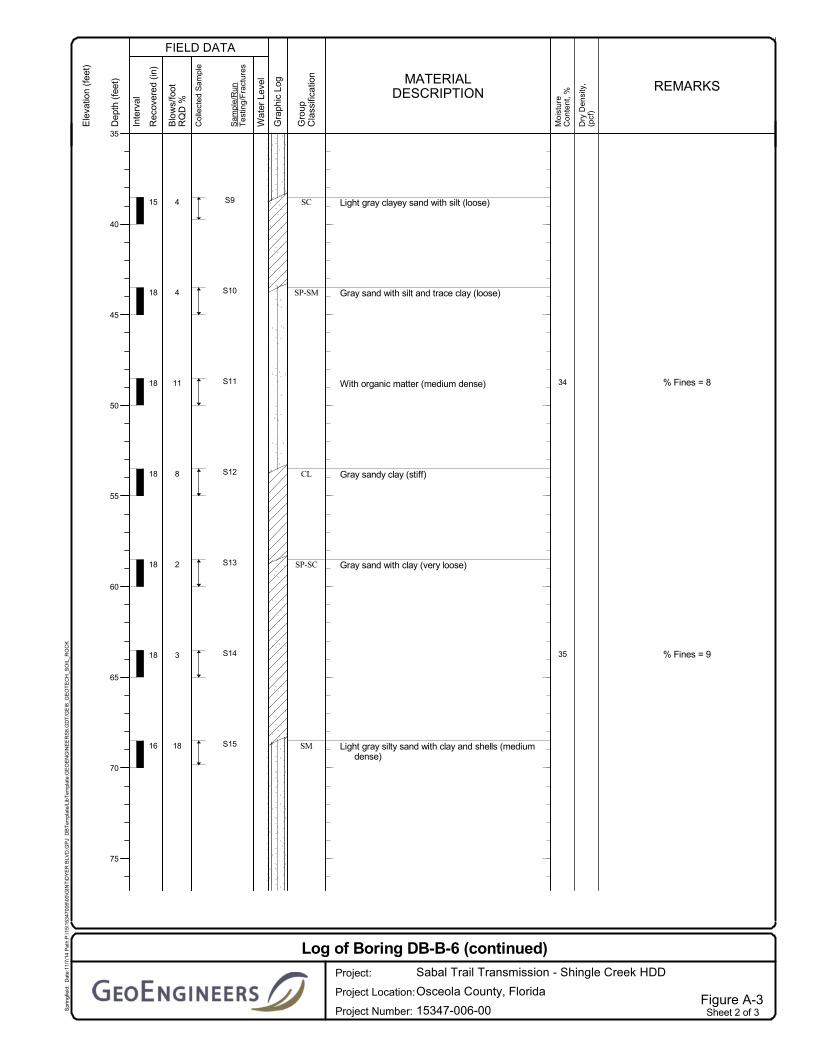
Boring DB-B-6
Drilling operations for boring DB-B-6 were completed on July 9 and July 10, 2014. Subsurface conditions
encountered at this location consisted of very loose to medium dense fine to medium sand with varying
amounts of silt and clay, and medium stiff to very stiff clay with varying amounts of silt and sand to the
maximum depth explored at approximately 80 feet bgs. Sand units at the site were generally very loose
to medium dense and clay units were medium stiff at depths less than 68 feet bgs. Below a depth of

November 17, 2014| Page 4 File No. 15347-006-00
approximately 68 feet bgs the observed soils were generally medium dense in sand units and stiff to very
stiff in clay units.
Boring DB-B-7
Drilling operations for boring DB-B-7 were completed on August 22, 2014. Subsurface conditions
encountered at this location consisted of loose to dense fine to medium sand with varying amounts of
clay and silt and soft to very stiff clay with varying amounts of sand to the maximum depth explored at 95
feet bgs. Sand units were generally loose and clay units were soft to medium stiff at depths less than 43
feet bgs. Below a depth of approximately 43 feet bgs the observed soils were generally medium dense to
dense in sand units and stiff to very stiff in clay units.
3.2.3 Groundwater Conditions
Because of the mud rotary drilling methods used to advance the boring, the groundwater level was not
observed in the borings.
3.3 Surface Conditions
3.3.1 General
We evaluated the surface conditions in the vicinity of the proposed HDD during our visit to the site on
April 25, 2014. During our site visit, we were accompanied by personnel from GIE and Spectra Energy
(Spectra). Photographs of site surface conditions along the project alignment are included in Figures 4
and 5.
3.3.2 Surface Description
The proposed HDD alignment trends roughly east to west (entry to exit), as shown in Figure 2. The
proposed entry point is located approximately 750 feet west of the Carroll Road and Dyer Boulevard
intersection. The ground surface elevation at the entry point is at an approximate elevation of 80 feet
(North American Vertical Datum [NAVD] 88).
The ground surface from entry remains relatively flat, sloping gently down toward Shingle Creek and the
surrounding wetlands. From the west bank of Shingle Creek the ground surface slopes upward to an
approximate elevation of 77 feet NAVD 88 before sloping down toward the exit point at an elevation of
approximately 70 feet NAVD 88. The area along the HDD alignment between the entry point and Shingle
Creek includes delineated wetlands and an adjacent residential development.
The exit point is located approximately 1,300 feet west of Shingle Creek within a relatively flat clearing
surrounded by wooded areas. The exit workspace is located between two wetland areas on the east and
west sides of the workspace.
The proposed pipe fabrication and stringing area extends approximately 3,500 feet westward from the
exit workspace. The fabrication and stringing workspace will be of sufficient length to string the carrier
pipe in one continuous section during pullback operations.

November 17, 2014| Page 5 File No. 15347-006-00
4.0 LIMITATIONS
We have prepared this report for use by Gulf Interstate Engineering, Sabal Trail Transmission, their
authorized agents, and other approved members of the design team involved with this project. The report
is not intended for use by others, and the information contained herein is not applicable to other sites.
The data and report should be provided to prospective contractors, but our report, conclusions and
interpretations should not be construed as a warranty of the subsurface conditions. The conclusions and
recommendations in this report should be applied in their entirety.
Variations in subsurface conditions are possible between the explorations. Subsurface conditions may
also vary with time. A contingency for unanticipated conditions should be included in the project budget
and schedule for such an occurrence. We recommend that sufficient monitoring, testing and consultation
be provided by GeoEngineers during construction to confirm that the conditions encountered are
consistent with those indicated by the explorations, to provide recommendations for design changes
should the conditions revealed during the work differ from those anticipated, and to evaluate whether
earthwork and pipeline installation activities comply with contract plans and specifications.
The scope of our services does not include services related to construction safety precautions. Our
recommendations are not intended to direct the contractor's methods, techniques, sequences or
procedures.
Within the limitations of scope, schedule and budget, our services have been executed in accordance
with generally accepted practices in this area at the time the report was prepared. No warranty or other
conditions, express, written or implied, should be understood.
Any electronic form, facsimile or hard copy of the original document (email, text, table and/or figure), if
provided, and any attachments are only a copy of the original document. The original document is stored
by GeoEngineers, and will serve as the official document of record.
Please refer to Appendix B, titled “Report Limitations and Guidelines for Use,” for additional information
pertaining to use of this report.
5.0 REFERENCES
NRCS Soil Survey, National Cooperative Soil Survey, Natural Resources Conservation Service, USDA,
(http://websoilsurvey.nrcs.usda.gov).
Pipeline Research Committee International (PRCI) of the American Gas Association “Installation of
Pipelines by Horizontal Directional Drilling, An Engineering Design Guide,” Contract No. PR-227-
9424, April 15, 1995.
Scott, T.M., and others, 2001, Geologic Map of the State of Florida, Florida Geological Survey,
1:1,000,000 Scale.
White, W.A., 1970, The Geomorphology of the Florida Peninsula: Florida Bureau of Geology, Bulletin no.
51.

FIGU
RE
S

9
6
8
5
7
11
13
10
12
Osceola
Orange
£¤17
£¤192
UV417
UV536
UV423
UV417
UV423
SABAL TRAIL TRANSMISSION PROJECTVICINITY MAP
SHINGLE CREEK HDDOSCEOLA COUNTY, FLORIDA
Figure 1
µ1 0 1
Miles
Notes:1. The locations of all features shown are approximate.2. This drawing is for information purposes. It is intended toassist in showing features discussed in an attached document.GeoEngineers, Inc. cannot guarantee the accuracy and contentof electronic files. The master file is stored by GeoEngineers, Inc. and will serve as the official record of this communication.Data Sources: ESRI Data & Maps, Street Maps 2008.Imagery from ESRI Data Online.Projection: NAD 1983, UTM Zone 17 North.
Offic
e: SP
RPa
th: P
:\15\1
5347
006\G
IS\Vic
inity
Maps
\Shin
gle C
reek H
DD.m
xdMa
p Rev
ised:
17 N
ovem
ber 2
014
mcle
veng
er
Polk Osceola
OrangeLakeSeminole
Brevard
Shingle Creek HDD
Proposed Hunter's Creek Line
H i l l a b e e
H i l l a b e eC r e e kC r e e k
Kissimmee
Deerfield HDD

SAND W/ SILT AND TRACESHELLS
SAND W/ TRACE SILT ANDGRAVEL
59'
38'
8°
SAND W/ CLAY AND SHELLS
CLAY W/ SAND AND SHELL FRAGMENTS
CLAYEY SAND W/ TRACE SHELLS
CLAY W/ SHELLS
SAND W/ SILTCLAY W/ SANDSILTY SAND
273221131616
1715201618
63
14688846
2018
328
114429976
148
3
CLAY W/ SAND AND SHELLS
SILTY SAND W/ CLAY AND SHELLS
SAND W/ CLAYSANDY CLAY
SAND W/ SILT AND TRACE CLAY
CLAYEY SAND W/ SILTSILTY SANDSANDY CLAY
SILTY SAND
CLAYEY SILT W/ SANDSAND W/ TRACE SILTSILTY SAND W/ TRACE CLAY
SAND W/ SILT
SANDY SILT W/ OCCASIONAL SHELL FRAGMENTS
SILTY CLAY
SANDY CLAY W/ SHELL FRAGMENTS
CLAYEY SAND W/ OCCASIONAL SHELL FRAGMENTS
CLAY W/ SAND
CLAYEY SAND
SILTY CLAY
SANDY CLAY
SILTY SANDSANDY TOPSOIL
15191915
9102969
13798
111285
CLAY
10°
70
70
70
70
80
70 70
70
60
80
80
80
80
70
80
X
X
X
X
XX
XX
X
X
X
X
X
MP
9.0
DB-B-7
DB-B-5
PROPOSEEDHDD EXIT POINT
N. 10280259.88000E. 1495777.94000
LAT. N28.32628397LONG. W81.44974061
50'300'
85'
225'
50'
22'
PROPOSEEDHDD ENTRY POINTN. 10280060.33045E. 1499172.11221LAT. N28.32576932LONG. W81.43918475
25'
SHEET NO.
DRAWN BY:
CHECKED BY:
SCALE:
DATE:
DATE:
W.O.:
DRAWINGNUMBER:
REV.
REV. DESCRIPTION DATE
PROPOSED 36" HDD PROFILE
DATUM:HORIZONTAL:VERTICAL:
UTM with NAD83 datum, Zone 17, US Foot; Central Meridian 81° WNAVD 88
PROPOSEDHDD EXIT POINT
PROPOSEDHDD ENTRY POINT
PROPOSED HUNTER'SCREEK LINE
PROPOSED 36" HORIZONTALDIRECTIONAL DRILL - 3402'
PROPERTY LINE(TYP.)
GROUND SURFACE (SURVEY)
W CARROLL ST.
HDD PROFILE20' OF COVER
HDD PROFILE 20' OF COVER
SABAL TRAIL TRANSMISSIONPROPOSED 36" HUNTER'S CREEK LINE
SITE PLAN AND PROFILESHINGLE CREEK HDD
WETLAND (TYP.) WATERBODYBOUNDARY (TYP.)
ADDITIONAL TEMPORARYWORKSPACE (TYP.)
PERMANENTEASEMENT (TYP.)
TEMPORARYWORKSPACE(TYP.)
EXISTING FENCE (TYP.)
EXISTING OVERHEADPOWERLINE (TYP.)
PROPOSED TEMPORARYEXIT WORKSPACE
PHC1PHT1
APPROXIMATE LOCATION OFPARCELS UNDER CONSTRUCTION
STRAIGHT REFERENCE LINE
SH
ING
LEC
REE
K
DB-B-6
SHINGLE CREEK
DB-B-5DB-B-6
DB-B-7
PROPOSED PRODUCT PIPE STRINGINGAND FABRICATION AREA TO BE WITHIN ANDALONG TEMPORARY WORKSPACE (3500' LONG)
-4.03 @ 4,200' R
CULVERT
PC1
PT1PHC1PHT1
PC2
PT2
4000' R
4000' R
PROPOSED 2.65 ACRESODD-SHAPED ENTRYWORKSPACE TO BE WITHINAND ALONG THETEMPORARY WORKSPACE
Notes:1. The locations of all features shown are approximate.2. This drawing is for information purposes. It is intended to assist in showing features discussed in an attached document.
GeoEngineers, Inc. can not guarantee the accuracy and content of electronic files. The master file is stored by GeoEngineers,Inc. and will serve as the official record of this communication.
3. Refer to the boring logs in the accompanying report for more detailed soil descriptions.4. The utilities shown on the drawing are based on survey data provided by Gulf Interstate Engineering. GeoEngineers, Inc. has
not verified the field location of the existing utilities.
Reference: Ground surface survey and survey data provided by Gulf Interstate Engineering. Aerial image taken from Google EarthPro, licensed to GeoEngineers, Inc., image dated 01/17/14.
Boring Location
Major Contour - 10' IntervalMinor Contour - 2' Interval
TYPE OF SOIL
LEGEND:
SPT (N)
DISCLAIMER: FOR FERC FINAL SUBMITTAL.THIS DRAWING IS NOT INTENDED FOR CONSTRUCTION.
ISSUED FOR PERMITTING
SURVEYED ROAD (TYP.)ACCESS ROAD (TYP.)
S13C
AR06
1

0.5 0 0.5
Miles
Notes:1. The locations of all features shown are approximate.2. This drawing is for information purposes. It is intendedto assist in showing features discussed in an attached document. GeoEngineers, Inc. cannot guarantee the accuracy and contentof electronic files. The master file is stored by GeoEngineers, Inc.and will serve as the official record of this communication.Projection: NAD 1983 UTM Zone 17N
HCL Mileposts
HCL Alignment
Proposed HDD Location
Florida GeologyQu: Undifferentiated
Offic
e: PO
RTPa
th: P:
\15\
1534
7006
_GIS\
GIS\0
0\MX
D\15
3470
0600
_Shin
gleCr
eekH
DD.m
xdMa
p Rev
ised:
06 N
ovem
ber 2
014
cca
brera
Qu
MP 9
MP 6
MP 8
MP 7
MP 11
MP 13
MP 10
MP 12
W Osceola Pkwy
Mill
R un Bl v
d
Flo r i da Pkwy
E Carroll St
Siesta Lago Dr
Still StBa
bb R
d
Ya tesRd
Flora Blvd
Lake Cecile Dr
Pam Rd
Mary Louis Ln
Prin
cess
Way
Sevil
le Dr
Brookmyra Dr
Sam
ple S
t
Hilda St
Dixie
Ln
Barn St
Dyer
Blvd
SOr
ange
Ave
E Town Center Blvd
Brad
ley D
r
Landstar Blvd
White BirchDr
Massa St
Lund Ave
Woodcrest Blvd
Colony Ave
Easy St
W Carroll St
Lanier Rd
Fiest a DrFloral Dr
Centervi ew Blvd
Home St
Mich
igan
Ave
Brookside Ave
Lake Calabay Dr
Old
Dixie
Hwy
Heather Way
Timucua Cir
NTh
acke
r Ave
Alexis Dr
Winfield DrPrince Ln
Lions
Ct
P a inter Ln
Cookie Ln
Van Lieu StBenita St
Carte
r Dr
Tulpa
n Dr
Bay A
ve
Cora
l Ave
E Osceola Pkwy
Lilly
Dr
Molo n a Dr
Red Ma p leDr
Osceola BlvdSa
dina
St
Derby Glen Dr
Chero kee Dr
Oakshire
Blvd
Rose
Dr
Donjay Ave
Palm
way S
t
Joelson Rd
Tamp
a Ave Lond ra
Ln
Shawnee Dr
Competit i o n Dr
Les Ct
Florid
a Ave
Hunters Isle Dr
Destiny Blvd
Royal Bay Blvd
Sports Club Way
Swo o p Cir
C onne r Ln
Windway Cir
Sierra CirNowry Ln
Oren Brown RdTown Loop Blvd
Smith
St
Paradis eDr
Be rkshire Ct
Astina Way
Tyler St
W Fletcher St
Stra
tford
Court St
Newc
ombe
Ln
Fernwood Dr
N Ho
aglan
d Bl
vd
Orch
id Ln
Marta Cir
Cecile Dr
Ashland Ln S
Estrella Dr
Dart Ave
San Gallo Dr
Coralwood Ct
Windrose Dr
Ken d rick Dr
Eldra Dr
Rio Ct
Hart
Ave
Target Rd
Abby Dr
Siesta Ln
Mary
St
Dean B St
Sain
t Cro
ix St
Iris D
r
Hidd
en L
ake S
t
Hawks Nest Dr
E Donegan Ave
Seven Dwarfs Ln
Bay S
t
Bamboo Ln
Peridot Cir
Kendall Ave
W Donegan Ave
Ball Park R d
Tacon Dr
WCe
da
rwood Cir
Lord
Barclay Dr
N Poinciana Blvd
Deso
to D
r
Sanchez Dr
Ocean St
Pomp
ano
Dr
E Lehigh St
Well
s Ct
Harbin Dr
Tina Ln
Mill Slough Rd
N Jo
hn Y
oung
Pkw
y
Thac
ker Ave
Town Center Blvd
Hunters Creek B lvd
Babb
Rd
E Osceola Pkwy
S Oran
ge Av
e
Dyer B
lvd
W Donegan Ave
Mill Slough Rd
Smith
St
D y erB l vdOren Brown Rd
Dyer Blvd
Old D
ixie H
wy
Babb
Rd
W Osceola Pkwy
Mich
igan
Ave
NJo
hnYo
u ng
Pkwy
Dyer
Blvd
W Osceola Pkwy
W Osceola Pkwy
W Carroll St
US-192 E
US-1
7 S
Central Florida Greenway N
US-1
7 N
US-192 W
Florida's Tpke S
Florida's Tpke N
Central Florida Greenway S
FL-423
US-192 E US-17 N
US-17 NFL-4
23
US-192 W
US-1
7 NUS
-17 N
US-192 E US-192 W US-192 W
Florida's Tpke N
US-192 E US-192 EUS-17 S
US-192 W
US-1
7 S
FL-42 3
FL-423
FL-417 N
W Vine St
FL-417 SFL-417 S
W Osceola PkwyFL-91
FL-91
FL-91
FL-91
527
527
41791
536
423
91
91
91
17
192
17
192
192
17
17
17
OsceolaOsceola
OrangeOrange
Seab
oard
Coa
st Lin
e Ra
i l roa
d
Shing
le
Creek
Mill
S lo u
gh
Jackson St Ditch
Lake Cecile
Denn John ParkDenn John Park
Hunter's Creek Golf Course
Rosehill Cemetery
Shingle Creek Cemetery
Valencia Community College
Parkway Middle School
Denn John Middle SchoolMill Creek Elementary School
Highlands Elementary School
Osceola Square Mall
Lake Buena Vista Factory Stores
Florida Hospital Kissimmee
Data Source: Florida geologic map data from Florida Geographic Data Library, http://www.fgdl.org/
Geologic MapSabal Trail Transmission Project
Shingle Creek HDDOsceola County, Florida
Figure 3
Shingle Creek HDD

FIGURE 4
Looking Westward along the HDD Alignment from the Entry Workspace
Looking Westward along the HDD Alignment between DB-B-5 and DB-B-6
Shingle Creek HDD Site Photographs

FIGURE 5
Looking Westward along the HDD Alignment toward the Product Pipe Stringing and Fabrication Area
Looking Eastward along the HDD Alignment within the vicinity of boring DB-B-7
Shingle Creek HDD Site Photographs

AP
PE
ND
ICE
S

APPENDIX A Field Explorations and Laboratory Testing

November 17, 2014| Page A-1 File No. 15347-006-00
APPENDIX A
FIELD EXPLORATIONS AND LABORATORY TESTING
Field Explorations
Subsurface conditions were explored at the site between July 9 and July 14, 2014, and again on August
22, 2014 by drilling three geotechnical borings (DB-B-5 through DB-B-7) using a track-mounted drilling rig.
The borings were drilled to depths up to 95 feet below ground surface (bgs). The borings were drilled
adjacent to the alignment of the proposed HDD in order to characterize the subsurface conditions for
HDD design.
The drilling operations were monitored by a GeoEngineers technician who examined and classified the
soils encountered, obtained representative samples, observed groundwater conditions where possible,
and prepared a detailed log of each exploration. The soil units encountered were classified visually in
general accordance with ASTM International (ASTM) D2488, which is described in Figure A-1. The
approximate locations of the explorations are shown in the Site Plan, Figure 2.
Soil samples were obtained from the borings at 5-foot depth intervals using a 1.5-inch inside-diameter
(I.D.) split spoon standard penetration test (SPT). The SPT sampler was driven 18 inches using a 140-
pound hammer with a 30-inch drop. The number of hammer blows required to drive the sampler each 6
inches of depth was recorded on field logs. Each boring was backfilled with Portland cement/bentonite
grout.
The relative density of the SPT samples recovered at each interval was evaluated based on correlations
with lab and field observations in general accordance with the values outlined in Table A-1 below.
TABLE A-1 CORRELATION BETWEEN BLOW COUNTS AND RELATIVE DENSITY 1
Cohesive Soils (Clay/Silt)
Parameter Very Soft Soft Medium Stiff Very Stiff Hard
Blows, N < 2 2 – 4 4 – 8 8 – 16 16 – 32 >32
Cohesionless Soils (Gravel/Sand/Silty Sand) 2
Parameter Very Loose Loose Medium Dense Dense Very Dense
Blows, N 0 – 4 4 – 10 10 – 30 30 – 50 > 50
Notes:
1 After Terzaghi, K and Peck, R.B., “Soil Mechanics in Engineering Practice,” John Wiley & Sons, Inc., 1962.
2 Classification applies to soils containing additional constituents; that is, organic clay, silty or clayey sand, etc.
The exploration logs are presented in Figures A-2 through A-4. The logs are based on our interpretation of
the field data and indicate the various types of soils encountered. They also indicate the approximate
depths at which the subsurface conditions change although the change may be more gradual than
depicted on the logs.

November 17, 2014| Page A-2 File No. 15347-006-00
Laboratory Testing
General
Soil samples obtained from the explorations were transported to our Baton Rouge, Louisiana office and
examined to confirm or modify field classifications. Representative samples were selected for laboratory
testing consisting of moisture content determinations, Atterberg Limits tests and sieve analyses. The
laboratory testing procedures are discussed in more detail below.
Moisture Content Testing
Moisture content tests were completed for representative samples obtained from the explorations in
general accordance with ASTM D2216. The results of these tests are presented on the exploration logs
in Figures A-2 through A-4 at the depths at which the samples were obtained.
Sieve Analyses
Sieve analyses were performed on selected coarse-grained samples in general accordance with ASTM
D422. The results of the sieve analyses were plotted and classified in general accordance with the
Unified Soil Classification System (USCS) and are presented in Figures A-5 and A-6. The percentage
passing the U.S. No. 200 sieve is shown on the boring logs at the respective sample depths.
Atterberg Limits Testing
Atterberg Limits were performed on selected fine grained soil samples in general accordance with ASTM
D4318. The tests were used to classify the soil as well as to evaluate its index properties. The results of
the Atterberg Limits testing are shown in Figures A-7 through A-9.

Blowcount is recorded for driven samplers as the numberof blows required to advance sampler 12 inches (ordistance noted). See exploration log for hammer weightand drop.
A "P" indicated sampler pused using the weight of the drill rig.
"WOH" indicates sampler pushed using the weight of the 140-pound SPT hammer.
NOTE: The reader must refer to the discussion in the report text and the logs of explorations for a proper understanding of subsurface conditions.Descriptions on the logs apply only at the specific exploration locations and at the time the explorations were made; they are not warranted to berepresentative of subsurface conditions at other locations or times.
Perched water observed at time ofexploration
SYMBOLS TYPICAL
KEY TO EXPLORATION LOGS
CC
CR
Groundwater observed at time ofexploration
Approximate location of soil stratachange within a geologic soil unit
Laboratory / Field Tests%FALCACPCSDSHAMCMDOCPMPPSATXUCVS
Standard Penetration Test (SPT)
Bulk or grab
Asphalt Concrete
Measured groundwater level inexploration, well, or piezometer
DESCRIPTIONSLETTER
Distinct contact between soil strata orgeologic units
Material Description Contact
Approximate location of soil stratachange within a geologic soil unit
Distinct contact between soil strata orgeologic units
TS
ADDITIONAL MATERIAL SYMBOLS
AC
Cement Concrete
Sampler Symbol Descriptions
GRAPH
Topsoil/Forest Duff/Sod
Percent finesAtterberg limitsChemical analysisLaboratory compaction testConsolidation testDirect shearHydrometer analysisMoisture contentMoisture content and dry densityOrganic contentPermeability or hydraulic conductivityPocket penetrometerSieve analysisTriaxial compressionUnconfined compressionVane shear
Piston
Crushed Rock/Quarry Spalls
Graphic Log Contact
GC
PT
OH
CH
MH
OL
ORGANIC CLAYS AND SILTS OFMEDIUM TO HIGH PLASTICITY
GM
GP
GW
DESCRIPTIONSTYPICAL
LETTERGRAPH
(APPRECIABLE AMOUNTOF FINES)
MORE THAN 50%RETAINED ON NO.
200 SIEVE
SYMBOLSMAJOR DIVISIONS
WELL-GRADED SANDS, GRAVELLYSANDS
SP
PEAT, HUMUS, SWAMP SOILS WITHHIGH ORGANIC CONTENTS
INORGANIC CLAYS OF HIGHPLASTICITY
(LITTLE OR NO FINES)
ORGANIC SILTS AND ORGANICSILTY CLAYS OF LOW PLASTICITY
INORGANIC CLAYS OF LOW TOMEDIUM PLASTICITY, GRAVELLYCLAYS, SANDY CLAYS, SILTY CLAYS,LEAN CLAYS
CLAYEY SANDS, SAND - CLAYMIXTURES
SILTY SANDS, SAND - SILTMIXTURES
CLAYEY GRAVELS, GRAVEL - SAND -CLAY MIXTURES
POORLY-GRADED GRAVELS,GRAVEL - SAND MIXTURES
ML
SC
SM
NOTE: Multiple symbols are used to indicate borderline or dual soil classifications
MORE THAN 50%PASSING NO. 200
SIEVE
MORE THAN 50%OF COARSEFRACTION
PASSING NO. 4SIEVE
CLEAN SANDS
GRAVELS WITHFINES
CLEANGRAVELS
HIGHLY ORGANIC SOILS
SILTSAND
CLAYS
SILTSAND
CLAYS
SANDAND
SANDYSOILS
GRAVELAND
GRAVELLYSOILS
(LITTLE OR NO FINES)
FINEGRAINED
SOILS
COARSEGRAINED
SOILS
SW
MORE THAN 50%OF COARSEFRACTION
RETAINED ON NO.4 SIEVE
CL
WELL-GRADED GRAVELS, GRAVEL -SAND MIXTURES
POORLY-GRADED SANDS,GRAVELLY SAND
INORGANIC SILTS, ROCK FLOUR,CLAYEY SILTS WITH SLIGHTPLASTICITY
INORGANIC SILTS, MICACEOUS ORDIATOMACEOUS SILTY SOILS
SILTY GRAVELS, GRAVEL - SAND -SILT MIXTURES
(APPRECIABLE AMOUNTOF FINES)
SOIL CLASSIFICATION CHART
LIQUID LIMITGREATER THAN 50
LIQUID LIMITLESS THAN 50
SANDS WITHFINES
Shelby tube
Direct-Push
FIGURE A-1

TS
SM
CL
CL-ML
18
10
13
18
18
15
17
15
5
8
12
11
8
9
7
13
S1
S2
S3
S4
S5
S6
S7
S8
Brown sandy topsoil (loose, dry)
Dark brown silty fine sand (loose, dry)
Becomes medium dense and wet
Dark brown sandy clay (stiff, wet)
Grades to brown
Brown silty clay (medium stiff, wet)
Becomes stiff
23
24
% Fines = 12
LL = 21PI = 4
TotalDepth (ft)
HammerData
SystemDatum
StartChecked ByLogged By
JETDrillingMethodDrilled
Notes:
SNN
Surface Elevation (ft)Vertical Datum
Mud RotaryDriller
GroundwaterDepth toWater (ft)Date Measured
CME-45
Elevation (ft)
DrillingEquipment
LatitudeLongitude
28º 19' 32.8" N81º 26' 20.4" W Geographic
85
Upon completion, borehole backfilled full-depth with cement-bentonite grout.
Automatic140 (lbs) / 30 (in) Drop
Undetermined
N/A
Amdrill, Inc7/14/2014End
7/14/2014
Sheet 1 of 3Figure A-2
Log of Boring DB-B-5
Project Location:
Project:
Project Number:
Sabal Trail Transmission - Shingle Creek HDD
15347-006-00
Osceola County, Florida
Spr
ingf
ield
: D
ate:
11/7
/14
Pat
h:P
:\15\
1534
7006
\00\
GIN
T\D
YE
R B
LVD
.GP
J D
BT
empl
ate/
LibT
empl
ate:
GE
OE
NG
INE
ER
S8.
GD
T/G
EI8
_GE
OT
EC
H_S
OIL
_RO
CK
FIELD DATA
Ele
vatio
n (f
eet)
Dep
th (
feet
)
0
5
10
15
20
25
30
35
Col
lect
ed S
ampl
e
Gro
upC
lass
ifica
tion
Inte
rval
Rec
over
ed (
in)
Blo
ws/
foot
RQ
D %
Sam
ple/
Run
Tes
ting
/Fra
ctur
es
MATERIALDESCRIPTION
Gra
phic
Log
Wat
er L
evel
Moi
stur
eC
onte
nt,
%
Dry
Den
sity
,(p
cf)
REMARKS

SC
CH
CL
SC
CL
CL-ML
12
18
18
18
18
18
18
17
9
6
9
2
10
9
15
19
S9
S10
S11
S12
S13
S14
S15
S16
Brown silty clay (stiff, wet)
Brownish gray clayey sand (loose, wet)
Dark brown clay (medium stiff, wet)
Gray clay with sand (stiff, wet)
Becomes soft
Brownish gray clayey sand with occasional shellfragments (medium dense, wet)
Gray sandy clay with shell fragments (stiff, wet)
Gray silty clay (very stiff, wet)
47
29
LL = 44PI = 19
LL = 20PI = 4
Sheet 2 of 3Figure A-2
Log of Boring DB-B-5 (continued)
Project Location:
Project:
Project Number:
Sabal Trail Transmission - Shingle Creek HDD
15347-006-00
Osceola County, Florida
Spr
ingf
ield
: D
ate:
11/7
/14
Pat
h:P
:\15\
1534
7006
\00\
GIN
T\D
YE
R B
LVD
.GP
J D
BT
empl
ate/
LibT
empl
ate:
GE
OE
NG
INE
ER
S8.
GD
T/G
EI8
_GE
OT
EC
H_S
OIL
_RO
CK
FIELD DATA
Ele
vatio
n (f
eet)
Dep
th (
feet
)
35
40
45
50
55
60
65
70
75
Col
lect
ed S
ampl
e
Gro
upC
lass
ifica
tion
Inte
rval
Rec
over
ed (
in)
Blo
ws/
foot
RQ
D %
Sam
ple/
Run
Tes
ting
/Fra
ctur
es
MATERIALDESCRIPTION
Gra
phic
Log
Wat
er L
evel
Moi
stur
eC
onte
nt,
%
Dry
Den
sity
,(p
cf)
REMARKS

ML
18
18
19
15
S17
S18
Gray silty clay (very stiff, wet)
Dark gray sandy silt with occasional shellfragments (stiff, wet)
Sheet 3 of 3Figure A-2
Log of Boring DB-B-5 (continued)
Project Location:
Project:
Project Number:
Sabal Trail Transmission - Shingle Creek HDD
15347-006-00
Osceola County, Florida
Spr
ingf
ield
: D
ate:
11/7
/14
Pat
h:P
:\15\
1534
7006
\00\
GIN
T\D
YE
R B
LVD
.GP
J D
BT
empl
ate/
LibT
empl
ate:
GE
OE
NG
INE
ER
S8.
GD
T/G
EI8
_GE
OT
EC
H_S
OIL
_RO
CK
FIELD DATA
Ele
vatio
n (f
eet)
Dep
th (
feet
)
80
85
Col
lect
ed S
ampl
e
Gro
upC
lass
ifica
tion
Inte
rval
Rec
over
ed (
in)
Blo
ws/
foot
RQ
D %
Sam
ple/
Run
Tes
ting
/Fra
ctur
es
MATERIALDESCRIPTION
Gra
phic
Log
Wat
er L
evel
Moi
stur
eC
onte
nt,
%
Dry
Den
sity
,(p
cf)
REMARKS

SP
SM
SP
CL-ML
SM
CL
SM
12
16
12
12
13
18
11
18
3
8
14
6
7
9
9
2
S1
S2
S3
S4
S5
S6
S7
S8
Brown sand with silt (very loose)
Tan and gray silty sand with trace clay (loose)
Light gray sand with trace silt (medium dense)
Light gray clayey silt with sand (medium stiff)
Light gray silty sand (loose)
Light gray sandy clay (stiff)
Light gray silty sand (very loose)
25
24
% Fines = 56
% Fines = 15
TotalDepth (ft)
HammerData
SystemDatum
StartChecked ByLogged By
JETDrillingMethodDrilled
Notes:
DAS
Surface Elevation (ft)Vertical Datum
Mud RotaryDriller
GroundwaterDepth toWater (ft)Date Measured
CME-45
Elevation (ft)
DrillingEquipment
LatitudeLongitude
28º 19' 33.5" N81º 26' 34.6" W Geographic
80
Upon completion, borehole backfilled full-depth with cement-bentonite grout.
Automatic140 (lbs) / 30 (in) Drop
Undetermined
N/A
Amdrill, Inc7/9/2014End
7/10/2014
Sheet 1 of 3Figure A-3
Log of Boring DB-B-6
Project Location:
Project:
Project Number:
Sabal Trail Transmission - Shingle Creek HDD
15347-006-00
Osceola County, Florida
Spr
ingf
ield
: D
ate:
11/7
/14
Pat
h:P
:\15\
1534
7006
\00\
GIN
T\D
YE
R B
LVD
.GP
J D
BT
empl
ate/
LibT
empl
ate:
GE
OE
NG
INE
ER
S8.
GD
T/G
EI8
_GE
OT
EC
H_S
OIL
_RO
CK
FIELD DATA
Ele
vatio
n (f
eet)
Dep
th (
feet
)
0
5
10
15
20
25
30
35
Col
lect
ed S
ampl
e
Gro
upC
lass
ifica
tion
Inte
rval
Rec
over
ed (
in)
Blo
ws/
foot
RQ
D %
Sam
ple/
Run
Tes
ting
/Fra
ctur
es
MATERIALDESCRIPTION
Gra
phic
Log
Wat
er L
evel
Moi
stur
eC
onte
nt,
%
Dry
Den
sity
,(p
cf)
REMARKS
SC
SP-SM
CL
SP-SC
SM
15
18
18
18
18
18
16
4
4
11
8
2
3
18
S9
S10
S11
S12
S13
S14
S15
Light gray clayey sand with silt (loose)
Gray sand with silt and trace clay (loose)
With organic matter (medium dense)
Gray sandy clay (stiff)
Gray sand with clay (very loose)
Light gray silty sand with clay and shells (mediumdense)
34
35
% Fines = 8
% Fines = 9
Sheet 2 of 3Figure A-3
Log of Boring DB-B-6 (continued)
Project Location:
Project:
Project Number:
Sabal Trail Transmission - Shingle Creek HDD
15347-006-00
Osceola County, Florida
Spr
ingf
ield
: D
ate:
11/7
/14
Pat
h:P
:\15\
1534
7006
\00\
GIN
T\D
YE
R B
LVD
.GP
J D
BT
empl
ate/
LibT
empl
ate:
GE
OE
NG
INE
ER
S8.
GD
T/G
EI8
_GE
OT
EC
H_S
OIL
_RO
CK
FIELD DATA
Ele
vatio
n (f
eet)
Dep
th (
feet
)
35
40
45
50
55
60
65
70
75
Col
lect
ed S
ampl
e
Gro
upC
lass
ifica
tion
Inte
rval
Rec
over
ed (
in)
Blo
ws/
foot
RQ
D %
Sam
ple/
Run
Tes
ting
/Fra
ctur
es
MATERIALDESCRIPTION
Gra
phic
Log
Wat
er L
evel
Moi
stur
eC
onte
nt,
%
Dry
Den
sity
,(p
cf)
REMARKS

CL20 S16 Light gray clay with sand and shells (very stiff) 42 LL = 50PI = 25
Sheet 3 of 3Figure A-3
Log of Boring DB-B-6 (continued)
Project Location:
Project:
Project Number:
Sabal Trail Transmission - Shingle Creek HDD
15347-006-00
Osceola County, Florida
Spr
ingf
ield
: D
ate:
11/7
/14
Pat
h:P
:\15\
1534
7006
\00\
GIN
T\D
YE
R B
LVD
.GP
J D
BT
empl
ate/
LibT
empl
ate:
GE
OE
NG
INE
ER
S8.
GD
T/G
EI8
_GE
OT
EC
H_S
OIL
_RO
CK
FIELD DATA
Ele
vatio
n (f
eet)
Dep
th (
feet
)
80C
olle
cted
Sam
ple
Gro
upC
lass
ifica
tion
Inte
rval
Rec
over
ed (
in)
Blo
ws/
foot
RQ
D %
Sam
ple/
Run
Tes
ting
/Fra
ctur
es
MATERIALDESCRIPTION
Gra
phic
Log
Wat
er L
evel
Moi
stur
eC
onte
nt,
%
Dry
Den
sity
,(p
cf)
REMARKS

SP
SM
CH
SP
CL
18
16
12
18
18
18
12
18
6
4
8
8
8
6
14
3
S1
S2
S3
S4
S5
S6
S7
S8
Brown fine sand with trace silt and gravel (loose,moist)
Becomes fine sand
Grades to dark gray
Gray silty sand (loose, moist)
Gray clay with sand (medium stiff, moist)
Light brown fine sand with silt (medium dense,moist)
Gray clay with shells (soft, wet)
21
29
23
% Fines = 3
% Fines = 23
LL = 108PI = 74
TotalDepth (ft)
HammerData
SystemDatum
StartChecked ByLogged By
JETDrillingMethodDrilled
Notes:
CGM
Surface Elevation (ft)Vertical Datum
Mud RotaryDriller
GroundwaterDepth toWater (ft)Date Measured
CME-45
Elevation (ft)
DrillingEquipment
LatitudeLongitude
28º 19' 34.7" N81º 26' 51.7" W Geographic
95
Upon completion, borehole backfilled full-depth with cement-bentonite grout.
Automatic140 (lbs) / 30 (in) Drop
Undetermined
N/A
Amdrill, Inc8/22/2014End
8/22/2014
Sheet 1 of 3Figure A-4
Log of Boring DB-B-7
Project Location:
Project:
Project Number:
Sabal Trail Transmission - Shingle Creek HDD
15347-006-00
Osceola County, Florida
Spr
ingf
ield
: D
ate:
11/7
/14
Pat
h:P
:\15\
1534
7006
\00\
GIN
T\D
YE
R B
LVD
.GP
J D
BT
empl
ate/
LibT
empl
ate:
GE
OE
NG
INE
ER
S8.
GD
T/G
EI8
_GE
OT
EC
H_S
OIL
_RO
CK
FIELD DATA
Ele
vatio
n (f
eet)
Dep
th (
feet
)
0
5
10
15
20
25
30
35
Col
lect
ed S
ampl
e
Gro
upC
lass
ifica
tion
Inte
rval
Rec
over
ed (
in)
Blo
ws/
foot
RQ
D %
Sam
ple/
Run
Tes
ting
/Fra
ctur
es
MATERIALDESCRIPTION
Gra
phic
Log
Wat
er L
evel
Moi
stur
eC
onte
nt,
%
Dry
Den
sity
,(p
cf)
REMARKS

SP-SM
SC
CL
18
18
18
18
18
18
18
18
6
18
16
20
15
17
16
16
S9
S10
S11
S12
S13
S14
S15
S16
Becomes clay with fine sand
Gray sand with silt and trace shells (mediumdense, moist)
With trace gravel
Gray clayey fine sand with trace shells (mediumdense, moist)
Becomes clayey fine sand and dry
Gray clay with fine sand and shell fragments(very stiff, moist)
45
28
39
LL = 45PI = 19
% Fines = 10% Gravel = 1
% Fines = 19
Sheet 2 of 3Figure A-4
Log of Boring DB-B-7 (continued)
Project Location:
Project:
Project Number:
Sabal Trail Transmission - Shingle Creek HDD
15347-006-00
Osceola County, Florida
Spr
ingf
ield
: D
ate:
11/7
/14
Pat
h:P
:\15\
1534
7006
\00\
GIN
T\D
YE
R B
LVD
.GP
J D
BT
empl
ate/
LibT
empl
ate:
GE
OE
NG
INE
ER
S8.
GD
T/G
EI8
_GE
OT
EC
H_S
OIL
_RO
CK
FIELD DATA
Ele
vatio
n (f
eet)
Dep
th (
feet
)
35
40
45
50
55
60
65
70
75
Col
lect
ed S
ampl
e
Gro
upC
lass
ifica
tion
Inte
rval
Rec
over
ed (
in)
Blo
ws/
foot
RQ
D %
Sam
ple/
Run
Tes
ting
/Fra
ctur
es
MATERIALDESCRIPTION
Gra
phic
Log
Wat
er L
evel
Moi
stur
eC
onte
nt,
%
Dry
Den
sity
,(p
cf)
REMARKS

SP-SC
18
18
18
18
13
21
32
27
S17
S18
S19
S20
Becomes stiff
Becomes very stiff
Gray sand with clay and shells (medium dense,moist)
34
28
LL = 46PI = 19
% Fines = 6% Gravel = 8
Sheet 3 of 3Figure A-4
Log of Boring DB-B-7 (continued)
Project Location:
Project:
Project Number:
Sabal Trail Transmission - Shingle Creek HDD
15347-006-00
Osceola County, Florida
Spr
ingf
ield
: D
ate:
11/7
/14
Pat
h:P
:\15\
1534
7006
\00\
GIN
T\D
YE
R B
LVD
.GP
J D
BT
empl
ate/
LibT
empl
ate:
GE
OE
NG
INE
ER
S8.
GD
T/G
EI8
_GE
OT
EC
H_S
OIL
_RO
CK
FIELD DATA
Ele
vatio
n (f
eet)
Dep
th (
feet
)
80
85
90
95
Col
lect
ed S
ampl
e
Gro
upC
lass
ifica
tion
Inte
rval
Rec
over
ed (
in)
Blo
ws/
foot
RQ
D %
Sam
ple/
Run
Tes
ting
/Fra
ctur
es
MATERIALDESCRIPTION
Gra
phic
Log
Wat
er L
evel
Moi
stur
eC
onte
nt,
%
Dry
Den
sity
,(p
cf)
REMARKS

Note: This report may not be reproduced, except in full, without written approval of GeoEngineers, Inc. Test results are applicable only to the specific sample on which they were performed, and should not be interpreted as representative of any other samples obtained at other times, depths or locations, or generated by separate operations or processes.
SANDSILT OR CLAYCOBBLES
GRAVELCOARSE MEDIUM FINECOARSE FINE
0
10
20
30
40
50
60
70
80
90
100
0.0010.010.11101001000
PER
CEN
T PA
SSIN
G B
Y W
EIG
HT
.
GRAIN SIZE IN MILLIMETERS
U.S. STANDARD SIEVE SIZE
3/8”3” 1.5” #4 #10 #20 #200#40 #60 #1003/4”
Sieve Analysis Results
Shingle Creek HDDOsceola County, Florida
Figure A-5
SymbolExploration
NumberSample Depth
(feet) Soil ClassificationDB-B-5 8.5 – 10.0 Brown poorly graded silty SAND (SM)
DB-B-6 48.5 – 50.0Gray poorly graded fine to medium SAND with
silt (SP-SM)
DB-B-7 8.5 – 10.0 Brown poorly graded fine SAND (SP)

Note: This report may not be reproduced, except in full, without written approval of GeoEngineers, Inc. Test results are applicable only to the specific sample on which they were performed, and should not be interpreted as representative of any other samples obtained at other times, depths or locations, or generated by separate operations or processes.
SANDSILT OR CLAYCOBBLES
GRAVELCOARSE MEDIUM FINECOARSE FINE
0
10
20
30
40
50
60
70
80
90
100
0.0010.010.11101001000
PER
CEN
T PA
SSIN
G B
Y W
EIG
HT
.
GRAIN SIZE IN MILLIMETERS
U.S. STANDARD SIEVE SIZE
3/8”3” 1.5” #4 #10 #20 #200#40 #60 #1003/4”
Sieve Analysis Results
Shingle Creek HDDOsceola County, Florida
Figure A-6
SymbolExploration
NumberSample Depth
(feet) Soil Classification
DB-B-7 48.5 – 50.0Gray poorly graded fine to medium SAND with
silt (SP-SM)
DB-B-7 63.5 – 65.0 Gray Clayey fine to medium SAND (SC)
DB-B-7 88.5 – 90.0 Gray poorly graded fine to medium SAND with
clay (SP-SC)

0
10
20
30
40
50
60
70
80
0 10 20 30 40 50 60 70 80 90 100
Pla
stic
ity In
dex
Liquid Limit
PLASTICITY CHART
Note: This report may not be reproduced, except in full, without written approval of GeoEngineers, Inc. Test results are applicable only to the specific sample on which they were performed, and should not be interpreted as representative of any other samples obtained at other times, depths or locations, or generated by separate operations or processes.
CL-ML ML or OL
CL or OL
OH and MH
CH or OH
SymbolExploration
NumberSample Depth
(feet)Moisture Content
(%)Liquid Limit
(%)Plasticity Index
(%) Soil DescriptionDB-B-5 28.5 – 30.0 24 21 4 Brown silty CLAY (CL-ML)DB-B-5 48.5 – 50.0 47 44 19 Gray CLAY with sand (CL)DB-B-5 73.5 – 75.0 24 20 4 Gray silty CLAY (CL-ML)
Atterberg Limits Test Results
Shingle Creek HDDOsceola County, Florida
Figure A-7

0
10
20
30
40
50
60
70
80
0 10 20 30 40 50 60 70 80 90 100 110
Pla
stic
ity In
dex
Liquid Limit
PLASTICITY CHART
Note: This report may not be reproduced, except in full, without written approval of GeoEngineers, Inc. Test results are applicable only to the specific sample on which they were performed, and should not be interpreted as representative of any other samples obtained at other times, depths or locations, or generated by separate operations or processes.
CL-ML ML or OL
CL or OL
OH and MH
CH or OH
SymbolExploration
NumberSample Depth
(feet)Moisture Content
(%)Liquid Limit
(%)Plasticity Index
(%) Soil DescriptionDB-B-6 78.5 – 80.0 42 50 25 Light gray CLAY with sand and shells (CH)DB-B-7 23.5 – 25.0 23 108 74 Gray CLAY with sand (CH)DB-B-7 38.5 – 40.0 45 45 19 Gray CLAY with sand (CL)
Atterberg Limits Test Results
Shingle Creek HDDOsceola County, Florida
Figure A-8

0
10
20
30
40
50
60
70
80
0 10 20 30 40 50 60 70 80 90 100 110
Pla
stic
ity In
dex
Liquid Limit
PLASTICITY CHART
Note: This report may not be reproduced, except in full, without written approval of GeoEngineers, Inc. Test results are applicable only to the specific sample on which they were performed, and should not be interpreted as representative of any other samples obtained at other times, depths or locations, or generated by separate operations or processes.
CL-ML ML or OL
CL or OL
OH and MH
CH or OH
SymbolExploration
NumberSample Depth
(feet)Moisture Content
(%)Liquid Limit
(%)Plasticity Index
(%) Soil DescriptionDB-B-7 78.5 – 80.0 34 46 19 Gray CLAY with sand and shells (CL)
Atterberg Limits Test Results
Shingle Creek HDDOsceola County, Florida
Figure A-9

APPENDIX B Report Limitations and Guidelines for Use

November 17, 2014| Page B-1 File No. 15347-006-00
APPENDIX B
REPORT LIMITATIONS AND GUIDELINES FOR USE1
This appendix provides information to help you manage your risks with respect to the use of this report.
Geotechnical and Environmental Services Are Performed for Specific Purposes, Persons and
Projects
This report has been prepared for the exclusive use of Gulf Interstate Engineering, Sabal Trail
Transmission and their authorized agents. This report is not intended for use by others, and the
information contained herein is not applicable to other sites.
GeoEngineers structures our services to meet the specific needs of our clients. For example, a
geotechnical or geologic study conducted for a civil engineer or architect may not fulfill the needs of a
construction contractor or even another civil engineer or architect that are involved in the same project.
Similarly, an environmental assessment study conducted for a property owner may not fulfill the needs of
a prospective purchaser of the same property. Because each study is unique, each report is unique,
prepared solely for the specific client and project site. Our report is prepared for the exclusive use of our
Client. No other party may rely on the product of our services unless we agree in advance to such
reliance in writing. This is to provide our firm with reasonable protection against open-ended liability
claims by third parties with whom there would otherwise be no contractual limits to their actions. Within
the limitations of scope, schedule and budget, our services have been executed in accordance with our
Agreement with the Client and generally accepted geotechnical practices in this area at the time this
report was prepared. This report should not be applied for any purpose or project except the one
originally contemplated.
A Geotechnical Engineering or Environmental Report Is Based on a Unique Set of
Project-Specific Factors
This report has been prepared for the proposed Shingle Creek HDD located in Osceola County, Florida.
GeoEngineers considered a number of unique, project-specific factors when establishing the scope of
services for this project and report. Unless GeoEngineers specifically indicates otherwise, do not rely on
this report if it was:
■ not prepared for you,
■ not prepared for your project,
■ not prepared for the specific site explored, or
■ completed before important project changes were made.
For example, changes that can affect the applicability of this report include those that affect:
1 Developed based on material provided by ASFE/The Best People on Earth, Professional Firms Practicing in the
Geosciences; www.asfe.org.

November 17, 2014| Page B-2 File No. 15347-006-00
■ the function of the proposed structure;
■ elevation, configuration, location, orientation or weight of the proposed structure;
■ composition of the design team; or
■ project ownership.
If important changes are made after the date of this report, GeoEngineers should be given the opportunity
to review our interpretations and recommendations and provide written modifications or confirmation, as
appropriate.
Subsurface Conditions Can Change
This report is based on conditions that existed at the time the study was performed. The findings and
conclusions of this report may be affected by the passage of time, by manmade events such as
construction on or adjacent to the site, by new releases of hazardous substances, or by natural events
such as floods, earthquakes, slope instability or groundwater fluctuations. Always contact GeoEngineers
before applying a report to determine if it remains applicable.
Most Geotechnical and Environmental Findings Are Professional Opinions
Our interpretations of subsurface conditions are based on field observations and laboratory test results
from widely spaced sampling locations at the site. Site exploration identifies subsurface conditions only
at those points where subsurface tests are conducted or samples are taken. GeoEngineers reviewed
field and laboratory data and then applied our professional judgment to render an opinion about
subsurface conditions throughout the site. Actual subsurface conditions may differ, sometimes
significantly, from those indicated in this report. Our report, conclusions and interpretations should not
be construed as a warranty of the subsurface conditions.
Do Not Redraw the Exploration Logs
Geotechnical engineers and geologists prepare final boring and testing logs based upon their
interpretation of field logs and laboratory data. To prevent errors or omissions, the logs included in a
geotechnical engineering or geologic report should never be redrawn for inclusion in architectural or other
design drawings. Only photographic or electronic reproduction is acceptable, but recognize that
separating logs from the report can elevate risk.
Contractors Are Responsible for Site Safety on Their Own Construction Projects
Our geotechnical recommendations are not intended to direct the contractor’s procedures, methods,
schedule or management of the work site. The contractor is solely responsible for job site safety and for
managing construction operations to minimize risks to on-site personnel and to adjacent properties.
Read These Provisions Closely
Some clients, design professionals and contractors may not recognize that the geoscience practices
(geotechnical engineering or geology) are far less exact than other engineering and natural science
disciplines. This lack of understanding can create unrealistic expectations that could lead to
disappointments, claims and disputes. GeoEngineers includes these explanatory “limitations” provisions
in our reports to help reduce such risks. Please confer with GeoEngineers if you are unclear how these
“Report Limitations and Guidelines for Use” apply to your project or site.

Have we delivered World Class Client Service?
Please let us know by visiting www.geoengineers.com/feedback.