Georgia DOT Research Project 12-38 Final Report By: … · Georgia DOT Research Project 12-38 Final...
158
Georgia DOT Research Project 12-38 Final Report Feasibility Study to Determine the Economic and Operational Benefits of Utilizing Unmanned Aerial Vehicles (UAVs) By: Javier Irizarry, Ph.D., P.E., CGP Eric N. Johnson, Ph.D. Georgia Institute of Technology Contract with Georgia Department of Transportation May 6, 2014 The contents of this report reflect the views of the author(s) who is (are) responsible for the facts and the accuracy of the data presented herein. The contents do not necessarily reflect the official views or policies of the Georgia Department of Transportation or of the Federal Highway Administration. This report does not constitute a standard, specification, or regulation.
Transcript of Georgia DOT Research Project 12-38 Final Report By: … · Georgia DOT Research Project 12-38 Final...

Georgia DOT Research Project 12-38
Final Report
Feasibility Study to Determine the Economic and Operational Benefits of Utilizing Unmanned
Aerial Vehicles (UAVs)
By:
Javier Irizarry, Ph.D., P.E., CGP
Eric N. Johnson, Ph.D.
Georgia Institute of Technology
Contract with
Georgia Department of Transportation
May 6, 2014
The contents of this report reflect the views of the author(s) who is (are) responsible for the
facts and the accuracy of the data presented herein. The contents do not necessarily reflect the
official views or policies of the Georgia Department of Transportation or of the Federal
Highway Administration. This report does not constitute a standard, specification, or
regulation.

ii
1.Report No.: FHWA-GA-1H-12-38
2. Government Accession No.:
3. Recipient's Catalog No.:
4. Title and Subtitle:
Feasibility Study to Determine the Economic and
Operational Benefits of Utilizing Unmanned Aerial
Vehicles (UAVs)
5. Report Date: April 2014
6. Performing Organization Code: 12-38
7. Author(s): Javier Irizarry, Ph.D., P.E., CGP
Eric N. Johnson, Ph.D.
8. Performing Organ. Report No.:
9. Performing Organization Name and Address: Georgia Institute of Technology
225 North Ave NW Atlanta, GA 30332
10. Work Unit No.:
11. Contract or Grant No.: Georgia DOT Research Project 12-38
12. Sponsoring Agency Name and Address: Georgia Department of Transportation Office of Research 15 Kennedy Drive Forest Park, GA 30297-2534
13. Type of Report and Period Covered: Final; January 2013-April 2014 14. Sponsoring Agency Code:
15. Supplementary Notes:
16. Abstract: This project explored the feasibility of using Unmanned Aerial Systems (UASs) in Georgia
Department of Transportation (GDOT) operations. The research team conducted 24 interviews with
personnel in four GDOT divisions. Interviews focused on (1) the basic goals of the operators in each
division, (2) their major decisions for accomplishing those goals, and (3) the information requirements for
each decision. Following an interview validation process, a set of UASs design characteristics that fulfill
user requirements of each previously identified division was developed. A “House of Quality” viewgraph
was chosen to capture the relationships between GDOT tasks and potential UAS aiding those operations.
As a result, five reference systems are proposed. The UAS was broken into three components: vehicle,
control station, and system. This study introduces a variety of UAS applications in traffic management,
transportation and construction disciplines related to DOTs, such as the ability to get real time, digital
photographs/videos of traffic scenes, providing a "bird’s eye view" that was previously only available with
the assistance of a manned aircraft, integrating aerial data into GDOT drawing software programs, and
dealing with restricted or complicated access issues when terrain, area, or the investigated object make it
difficult for GDOT personnel to conduct a task. The results of this study could lead to further research on
design, development, and field-testing of UAVs for applications identified as beneficial to the Department.
17. Key Words:
Unmanned Aerial Vehicles, Unmanned Aerial
Systems, Operational Requirements, Technical
Requirements, Cost Analysis.
18. Distribution Statement:
19. Security Classification
(of this report):
Unclassified
20. Security
Classification (of
this page):
Unclassified
21. Number of
Pages:
xiv + 144
22. Price:
$74,984

iii
Acknowledgements The research team would like to acknowledge the Georgia Department of Transportation
for their support of the research project and the following individuals for their direct
involvement with the project.
GDOT Technical Advisory Committee: Binh H. Bui, Georgene Geary, and Carla
J. Sands
H. Claus Christmann – Graduate Student, Georgia Institute of Technology
Ebrahim P. Karan – Graduate Student, Georgia Institute of Technology
Personnel from the following areas: Construction, Engineering, Intermodal, and
Permits and Operations

iv
Executive Summary
In April of 2013, a team from the Georgia Institute of Technology entered into a
research project to explore the feasibility of using Unmanned Aerial Systems (UASs) in
Georgia Department of Transportation (GDOT) operations and to determine the
economic and operational benefits of this technology. Unmanned Aerial Systems are
normally comprised of a control station for a human operator and one or more Unmanned
Aerial Vehicles (UAVs). The utilized UAVs can be equipped with various sensors, such
as video or still cameras, including far and near infrared, radar or laser based range
finders, or specialized communication devices. The ground stations utilized by the human
operators can vary from portable computer based systems to fixed installations in
vehicles or dedicated control rooms.
The project lasted for a period of one year and the research team conducted several
interview sessions with a variety of directors or administrators in different GDOT
divisions and offices. The research team first studied all GDOT divisions and offices to
identify those that have the potential for using UASs. This analysis was performed by
investigating the operations, mission and sets of responsibilities that each division and
their internal offices have. At the same time, previous uses of UASs across all DOTs as
well as the current status of different civilian applications of UASs were investigated.
The result of this phase led to identifying four GDOT divisions with the potential for
using UASs as well as determining the potential uses of UASs across all GDOT divisions.
Semi-structured interviews with Subject Matter Experts in each identified division were
conducted and focused on (1) the basic goals of the operators in each division, (2) their
major decisions for accomplishing those goals, and (3) the information requirements for
each decision. All of the information was validated through feedback from the
interviewees and further analyzed to identify the tasks with the greatest potential use of
UASs.
Following the interview validation process, a set of UASs design characteristics that
fulfill user requirements of each previously identified division was developed. Among
them are the UAV platform (i.e. whether the vehicle is a fixed wing system or a rotary
wing system), the sensor and other device requirements, the payload components, the

v
sizing of the vehicle based on the required payload capacity in the context of the airframe
choice, and the power consumption (i.e. electric or gasoline powered system). In an effort
to visualize UASs specific interconnections, an adoption of a “House of Quality”
viewgraph has been chosen to capture the relationships between GDOT tasks and
potential UAS aiding those operations. As a result, five reference systems are proposed.
These systems capture the majority of the tasks identified through the interview process
and cover a wide spectrum of capabilities, expandability, but also availability. The UAS
was broken into three components: vehicle, control station, and system. The vehicle
component includes airframe hardware and its related requirements. The control station
component includes the requirements related to the user interface of the control station,
the control station’s hardware that will be used outdoors, and transportation of the control
station. Specific guidance, navigation, and control aspects that mainly contain capability
features of the reference systems are grouped into the system component. This study
introduces a variety of UAS applications in traffic management, transportation and
construction disciplines related to DOTs, such as the ability to get real time, digital
photographs/videos of traffic scenes, providing a "bird’s eye view" that was previously
only available with the assistance of a manned aircraft, integrating aerial data into GDOT
drawing software programs, and dealing with restricted or complicated access issues
when terrain, area, or the investigated object make it difficult for GDOT personnel to
conduct a task. The results of this study could lead to further research on design,
development, and field-testing of UAVs for applications identified as beneficial to the
Department.
Keywords: Unmanned Aerial Vehicles, Unmanned Aerial Systems, Operational
Requirements, Technical Requirements, Cost Analysis

vi
Table of Contents
Acknowledgements ............................................................................................................ iii
1. CHAPTER I ................................................................................................................ 1
1. Introduction ................................................................................................................. 1
1.1. Overview .............................................................................................................. 1
1.2. Research Objectives ............................................................................................. 5
1.3. Research Methodology ........................................................................................ 6
1.4. Expected Results ................................................................................................ 11
2. CHAPTER II ............................................................................................................. 13
2. Literature Review...................................................................................................... 13
2.1. Traffic Surveillance ........................................................................................... 13
2.2. Traffic Simulation .............................................................................................. 15
2.3. Monitoring of Structures .................................................................................... 16
2.4. Avalanche Control ............................................................................................. 17
2.5. Aerial Assessment of Road Surface Condition .................................................. 18
2.6. Bridge Inspection ............................................................................................... 19
2.7. Safety Inspection at Construction Jobsites ........................................................ 20
3. CHAPTER III ........................................................................................................... 22
3. Analysis of GDOT divisions/offices ......................................................................... 22
3.1. Construction Division ........................................................................................ 28
3.2. Engineering Division ......................................................................................... 31
3.3. Intermodal Division ........................................................................................... 34
3.4. Permits and Operations Division ....................................................................... 36
4. CHAPTER IV ........................................................................................................... 39
4. Identification of Operational Requirements .............................................................. 39
4.1. Defining the Operational Tasks in the Division ................................................ 41
4.2. Studying the Environmental Conditions of the Workplace ............................... 47

vii
4.3. Analyzing the User Characteristics .................................................................... 48
4.4. Investigating the Current Tools/Technologies Used in Division’s Operations . 48
4.5. Identification of Technical Requirements .......................................................... 50
5. CHAPTER V ............................................................................................................ 54
5.1. Analysis of UAS Requirements ............................................................................. 54
5.1.1. Introduction ..................................................................................................... 54
5.1.2. UAS Technical Requirements ......................................................................... 55
5.1.3. Intra-system Correlations ................................................................................ 60
5.1.4. Operator Requirements ................................................................................... 62
5.2. Reference Systems ................................................................................................. 66
5.2.1. Commonalities ................................................................................................ 67
5.2.2. System A – Flying Camera ............................................................................. 67
5.2.3. System B – Flying Total Station ..................................................................... 70
5.2.4. System C – Perching Camera ......................................................................... 72
5.2.5. System D – Medium Altitude, Long Endurance (MALE) .............................. 75
5.2.6. System E – Complex Manipulation ................................................................ 78
6. CHAPTER VI ........................................................................................................... 83
6. Cost Analysis ............................................................................................................ 83
6.1. System A – Flying Camera ............................................................................. 83
6.2. System B – Flying Total Station ........................................................................ 84
6.3 System C – Perching Camera ............................................................................. 84
6.4 System D – Medium Altitude, Long Endurance ................................................. 85
6.5 System E – Complex Manipulation .................................................................... 86
6.6. Cost-Benefit Analysis ........................................................................................ 86
7. CHAPTER VII .......................................................................................................... 89
7. Recommendations for Future Work.......................................................................... 89
References ......................................................................................................................... 90
Appendix ........................................................................................................................... 94

viii
Appendix A: Interview Sheet........................................................................................ 95
1- Demographic Questions / User ....................................................................... 95
2- Operational Requirements .............................................................................. 96
3- Technology Analysis ...................................................................................... 97
4- Working Environment .................................................................................... 99
5- UAVs in Your Department /Office .............................................................. 100
Appendix B: IRB and Consent Forms ........................................................................ 102
Appendix C: Interview Validation Form (Example) .................................................. 105
Appendix D: Validated Tasks ..................................................................................... 109
Appendix E: Exemplary Process Descriptions for UAS-aided Tasks ........................ 128
Construction Site Measurements ............................................................................ 128
Traffic Signal Installation Inspection...................................................................... 128
Traffic Signal Installation Inspection...................................................................... 129
On-Site Traffic Inspection ...................................................................................... 129
On-Site Traffic Inspection ...................................................................................... 129
Airport Inspection ................................................................................................... 130
Bulk Material Measurement ................................................................................... 130
Bulk Material Measurement ................................................................................... 130
Bulk Material Measurement ................................................................................... 130
Rail Site Inspection ................................................................................................. 131
Traffic Data Collection ........................................................................................... 131
Speed Sample Measurement ................................................................................... 131
Speed Sample Measurement ................................................................................... 132
Traffic Count Measurement .................................................................................... 132
Turning Movement Measurement........................................................................... 132
Special Event Supervision ...................................................................................... 133
Post-Incident Inspection.......................................................................................... 133
Conventional Bridge Inspection ............................................................................. 133
ix
Detailed Bridge Inspection ..................................................................................... 133
Special Bridge Inspection ....................................................................................... 134
Special Bridge Inspection (Complex) ..................................................................... 134
Appendix F: Complete House of Quality Viewgraph................................................. 140
Appendix G: Reference System Technical Requirement Correlations....................... 141
Vehicle Intra-relations ............................................................................................ 141
Control Station Intra-relations ................................................................................ 141
System Intra-relations ............................................................................................. 142
Vehicle Control Station Inter-relations ................................................................... 142
Vehicle System Inter-relations ................................................................................ 143
Control Station System Inter-relations.................................................................... 143

x
List of Figures
Figure 1-1: UAV technology as safety inspection tool ....................................................... 4
Figure 1-2: Some of the aircraft that have been utilized for research in the Georgia Tech
UAV Research Facility, including a variety of configurations. ..................................... 5
Figure 1-3: Work plan flowchart ........................................................................................ 8
Figure 2-1: Example of UAV flight controller user interface – safety inspection
experiment .................................................................................................................... 21
Figure 3-1: GDOT divisions with the highest potential for benefitting from UAV
technology .................................................................................................................... 29
Figure 3-2: GDOT districts – main office and area offices (adopted from GDOT website,
access date: March 2013) ............................................................................................. 30
Figure 3-3: Organizational chart of GDOT construction division (adopted from GDOT
website, access date: March 2013) ............................................................................... 32
Figure 3-4: Organizational chart of GDOT engineering division (adopted from GDOT
website, access date: March 2013) ............................................................................... 34
Figure 3-5: Organizational chart of GDOT intermodal division (adopted from GDOT
website, access date: March 2013) ............................................................................... 35
Figure 3-6: Organizational chart of GDOT permits and operations division (adopted from
GDOT website, access date: March 2013) ................................................................... 38
Figure 4-1: User requirements identification workflow ................................................... 41
Figure 4-2: Operational requirements matrix ................................................................... 50
Figure 4-3: Technical requirements matrix ....................................................................... 51
Figure 5-1: House of Quality creation process ................................................................. 55
Figure 5-2: The correlations part of the House of Quality showing the interplay between
the technical requirements............................................................................................ 61
Figure 5-3: House of Quality for System A (Flying Camera) .......................................... 69
Figure 5-4: House of Quality for System B (Flying Total Station) .................................. 71
Figure 5-5: House of Quality for System C (Perching Camera) ....................................... 74
Figure 5-6: House of Quality for System D (MALE) ....................................................... 76
Figure 5-7: House of Quality for System E (Complex Manipulation) ............................. 79

xi
Figure 6-1: Extremely reduced House of Quality for all Systems, also showing estimated
rough order of magnitude cost. ................................................................................... 87

xii
List of Tables
Table 1-1: Summary of previous UASs applications by DOTs .............................................. 2
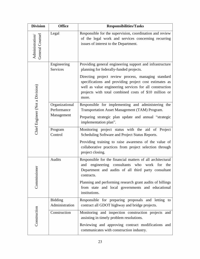
Table 3-1: GDOT divisions and offices and summary of their responsibilities (adopted from
GDOT website, access date: March 2013) ....................................................................... 22
Table 4-1: Demographic and work-related statistics of participants ..................................... 40
Table 4-2: Examples of the tasks performed by each GDOT division .................................. 41

xiii
List of Acronyms
ADAS Airborne Data Acquisition System
ADS-B Automatic Dependent Surveillance-Broadcast
AEC Architecture, Engineering, and Construction
ATC Air Traffic Control
COTS Commercial-Of-The-Shelf
DOT Department of Transportation
FAA Federal Aviation Administration
FDOT Florida Department of Transportation
FPV First-Person Video
GA General Aviation
GDOT Georgia Department of Transportation
GDTA Goal Directed Task Analysis
GIS Geographic Information Systems
GNC Guidance, Navigation, and Control
GNSS Global Navigation Satellite System
GPS Global Positioning System
GUI Graphical User Interface
GUST Georgia Tech UAV Simulation Tool
HERO Highway Emergency Response Operators
HoQ House of Quality
HMMWV High Mobility Multi-Purpose Wheeled Vehicles
INS Inertial Navigation System
IRB Institutional Review Board
LiDAR Light Detection and Ranging system
MALE Medium Altitude, Long Endurance
MANET Mobile Ad-hoc NETwork

xiv
NCRST National Consortium on Remote Sensing in Transportation
ODOT Ohio Department of Transportation
P3 Public-Private Partnership
PF Pilot-Flying
PNF Pilot-Non-Flying
R/C Radio controlled (flight)
R/F Radio Frequency
ROM Rough Order of Magnitude
SA Situational Awareness
SAS Stability Augmentation Systems
SLAM Simultaneous Location And Mapping
SME Subject Matter Expert
TAM Transportation Asset Management
TIA Transportation Investment Act
UAS Unmanned Aerial Systems
UAV Unmanned Aerial Vehicle
UDOT Utah Department of Transportation
UUV Unmanned Underwater Vehicles
VDOT Virginia Department of Transportation
VFR Visual Flight Rules
VTOL Vertical Take-Off and Landing
WSDOT Washington State Department of Transportation

1
1. CHAPTER I
1. Introduction
1.1. Overview
Unmanned Aerial Systems (UASs) are an emerging technology that can be widely
used in various civil applications, ranging from monitoring tasks to simple item
manipulation or cargo delivery scenarios. UASs are normally comprised of a portable
control station for the human operator and one or more Unmanned Aerial Vehicles
(UAVs). The utilized UAVs can be equipped with various sensors, such as video or still
cameras, including far and near infrared, radar or laser based range finders, or specialized
communication devices. Most UASs are capable of real-time data transfer between the
UAV(s) and the control station; some have additional on-board data storage capabilities
for enhanced data collection tasks. UASs can perform tasks similar to those that can be
done by manned vehicles, but often faster, safer, and at a lower cost (Puri 2005).
Although an initial wide spread application of UAS was within military operations,
having reached a permanent position in the military arsenals of many forces (Nisser and
Westin 2006), peaceful applications of these systems are currently investigated in border
patrol, search and rescue, damage investigations during or after natural disasters (e.g.
hurricanes, earthquakes, tsunamis), locating forest fires or farmland frost conditions,
monitoring criminal activities, mining activities, advertising, scientific surveys, and
securing pipelines and offshore oil platforms (Anand 2007). Due to the ability to utilize
various sensor devices and the potential to hover for a long period of time, UAS utilizing
rotary wing aircraft (e.g. quad- and other multicopters, as well as traditional helicopters)
are well suited as experimental platforms for different efforts investigating the
application of unmanned systems, such as autonomous surveillance/navigation (Krajník
et al. 2011), human-machine interaction (Ng and Sharlin 2011), or as sport training
assistant providing athletes with external imagery of their actions (Higuchi et al. 2011).
As the continuous improvement in function and performance of UASs promotes the need
for specific research to integrate this leading edge technology into various applications,
Departments of Transportation (DOTs) of several states have started using UAS
2
technology for different purposes from tracking highway construction projects and
performing structure inventories to road maintenance, monitoring roadside environmental
conditions as well as many other surveillance, traffic management or safety issues. Some
examples of previous application of UASs by various DOTs across the country are listed
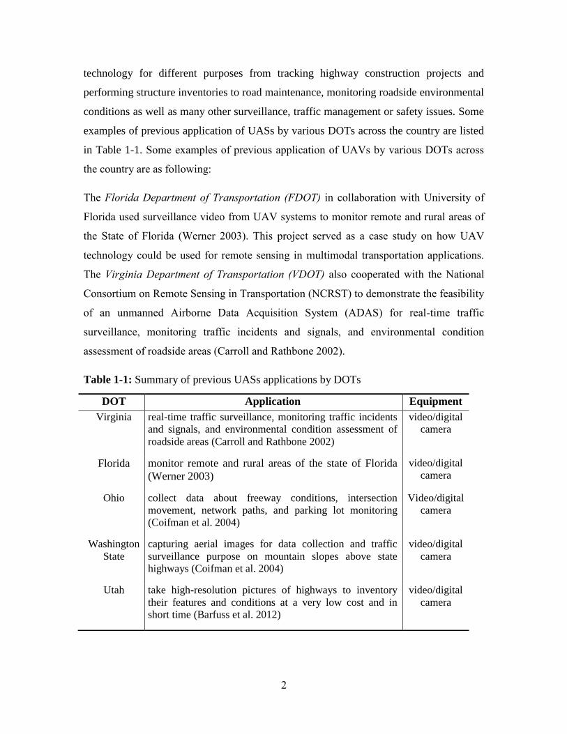
in Table 1-1. Some examples of previous application of UAVs by various DOTs across
the country are as following:
The Florida Department of Transportation (FDOT) in collaboration with University of
Florida used surveillance video from UAV systems to monitor remote and rural areas of
the State of Florida (Werner 2003). This project served as a case study on how UAV
technology could be used for remote sensing in multimodal transportation applications.
The Virginia Department of Transportation (VDOT) also cooperated with the National
Consortium on Remote Sensing in Transportation (NCRST) to demonstrate the feasibility
of an unmanned Airborne Data Acquisition System (ADAS) for real-time traffic
surveillance, monitoring traffic incidents and signals, and environmental condition
assessment of roadside areas (Carroll and Rathbone 2002).
Table 1-1: Summary of previous UASs applications by DOTs
DOT Application Equipment
Virginia real-time traffic surveillance, monitoring traffic incidents
and signals, and environmental condition assessment of
roadside areas (Carroll and Rathbone 2002)
video/digital
camera
Florida monitor remote and rural areas of the state of Florida
(Werner 2003)
video/digital
camera
Ohio collect data about freeway conditions, intersection
movement, network paths, and parking lot monitoring
(Coifman et al. 2004)
Video/digital
camera
Washington
State
capturing aerial images for data collection and traffic
surveillance purpose on mountain slopes above state
highways (Coifman et al. 2004)
video/digital
camera
Utah take high-resolution pictures of highways to inventory
their features and conditions at a very low cost and in
short time (Barfuss et al. 2012)
video/digital
camera
3
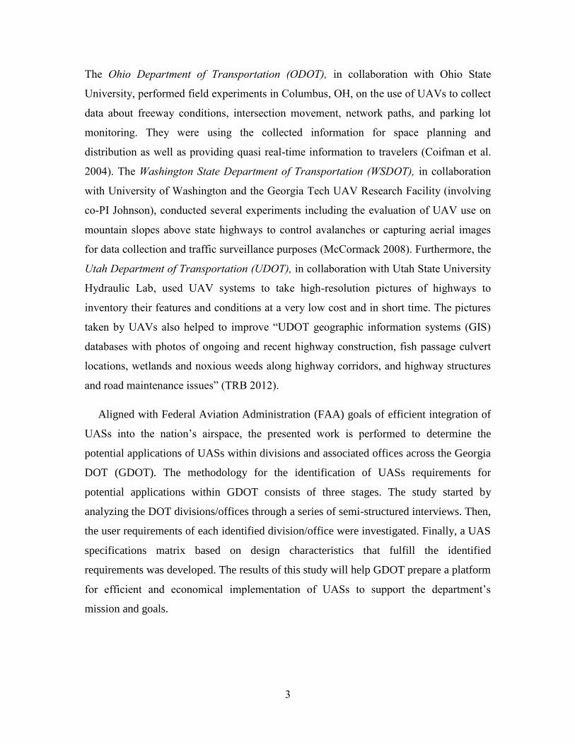
The Ohio Department of Transportation (ODOT), in collaboration with Ohio State
University, performed field experiments in Columbus, OH, on the use of UAVs to collect
data about freeway conditions, intersection movement, network paths, and parking lot
monitoring. They were using the collected information for space planning and
distribution as well as providing quasi real-time information to travelers (Coifman et al.
2004). The Washington State Department of Transportation (WSDOT), in collaboration
with University of Washington and the Georgia Tech UAV Research Facility (involving
co-PI Johnson), conducted several experiments including the evaluation of UAV use on
mountain slopes above state highways to control avalanches or capturing aerial images
for data collection and traffic surveillance purposes (McCormack 2008). Furthermore, the
Utah Department of Transportation (UDOT), in collaboration with Utah State University
Hydraulic Lab, used UAV systems to take high-resolution pictures of highways to
inventory their features and conditions at a very low cost and in short time. The pictures
taken by UAVs also helped to improve “UDOT geographic information systems (GIS)
databases with photos of ongoing and recent highway construction, fish passage culvert
locations, wetlands and noxious weeds along highway corridors, and highway structures
and road maintenance issues” (TRB 2012).
Aligned with Federal Aviation Administration (FAA) goals of efficient integration of
UASs into the nation’s airspace, the presented work is performed to determine the
potential applications of UASs within divisions and associated offices across the Georgia
DOT (GDOT). The methodology for the identification of UASs requirements for
potential applications within GDOT consists of three stages. The study started by
analyzing the DOT divisions/offices through a series of semi-structured interviews. Then,
the user requirements of each identified division/office were investigated. Finally, a UAS
specifications matrix based on design characteristics that fulfill the identified
requirements was developed. The results of this study will help GDOT prepare a platform
for efficient and economical implementation of UASs to support the department’s
mission and goals.

4
Irizarry (PI) and his research team (2012) studied the initial application of UAV
technology in the construction industry. In their study, a small-scale UAV was used as a
tool for exploring potential benefits to safety managers within the construction jobsite.
The UAV was an aerial quadrocopter which could be piloted remotely using a smart
phone, a tablet device, or a computer. Since the UAV was equipped with video cameras,
it could provide safety managers with fast access to aerial images as well as real-time
videos from a range of locations around the jobsite. Figure 1-1 shows the experimental
setup used in the study. The results of this study led to recommendations for the required
features of an ideal safety inspection assistant UAV. Autonomous navigation, vocal
interaction, high-resolution cameras, and collaborative user-interface environment are
some examples of those features.
Figure 1-1: UAV technology as safety inspection tool

5
Johnson (co-PI), and his research group within the UAV Research Facility in the
School of Aerospace Engineering at Georgia Tech, have been doing guidance, navigation,
and control work for unmanned system for nearly 20 years. An emphasis has been on
small unmanned aircraft capable of vertical takeoff and landing (VTOL), with an extreme
variety of different aircraft types utilized, some of which are shown in Figure 1-2. The
type of work they do is indicative of the kinds of capabilities that UAVs have gained in
that time period, including precision Global Positioning System (GPS)-based navigation,
vision-aiding capabilities, automatic real-time video processing, and increased autonomy
in general.
1.2. Research Objectives
It is envisioned that this feasibility study would ideally lead to further research on
design, development, and field-testing of UAVs for applications identified as beneficial
to the Department. It is also envisioned that this GDOT-based user-centered study for
developing UAV design characteristics will provide a platform for appropriate data
collection to facilitate FAA to accurately develop UAV integration policies and
certification requirements.
Figure 1-2: Some of the aircraft that have been utilized for research in the Georgia Tech
UAV Research Facility, including a variety of configurations.

6
This study investigates various divisions and offices within GDOT and determines the
user requirements for specific divisions that have the potential to implement UAV
technology. This will lead to a set of UAV design characteristics that fulfill user
requirements of each previously identified division. A cost benefit analysis will be finally
performed to realize the financial feasibility of applying UAV technology in each
selected division within GDOT. In summary the goals of the study include:
1. To identify user requirements for each division/office in GDOT that has the
potential to benefit from UAVs.
2. To identify UAV design characteristics based on the user requirements for each
GDOT division/office.
3. To perform a cost benefit analysis, comparing the UAV design and construction,
maintenance, and operation cost against potential cost savings due to performance
enhancement in specific GDOT department practices.
1.3. Research Methodology
Systems have traditionally been designed and developed through a technology-
centered perspective (Endsley et al. 2003). In such a perspective the designers would
accept the technology as is and would try to apply the very same technology in different
domains without considering the very important element of the ultimate end-user
(humans). In a technology-centered perspective, the end user and all its requirements
would be considered improperly identical in different domains. In this research, a user-
centered approach is employed. Unlike the technology-centered approach, the very first
issue that should be resolved in a user-center perspective is whether the technology is
usable considering the real users’ experience and their own requirements in a specific
domain. This user-centered usability-based step would provide a grounded base for
understanding the requirements for practical application of the technology in a domain.
Having the UAV technology might seem very useful for most GDOT practices but the
very first issue that should be resolved is whether this technology would be usable for
different applications within GDOT divisions and offices. A usable UAV system should
be designed firstly by investigating the user requirements across all divisions and offices
of GDOT and then identifying and developing a set of design characteristics for the UAV

7
based on the previously identified user requirements. Even when a real UAV is designed
based on user requirements, it should be tested using real users of the system to evaluate
its applicability and usability.
The work plan of this research has been illustrated in Figure 1-3 and the related
activities are described next. The whole research encompasses four phases of;
1. Analysis of GDOT divisions/offices,
2. Identification of user’s operational requirements in each identified division/office ,
3. Identification of UAV design characteristics for each identified division/office,
4. Cost-benefit analysis for each identified division/office based on the proposed
UAV for that division/office.
Phase 1: Analysis of GDOT Divisions (Chapter III)
All divisions and offices of GDOT would be studied to identify those that have the
potential for using UAVs. This analysis is performed by investigating the operations,
mission and sets of responsibilities that each division and their internal offices might
have. Furthermore, interviewing directors or administrators of each division or office
would help build a clearer picture of what would be general goals and tasks of different
divisions and offices.
A simultaneous study is conducted on investigating previous use of UAV across all
DOTs together with determining the current status of different civil applications of UAV.
A detailed review of various DOTs’ materials and reports together with a study of up-to-
date publications and research on UAV civil application is also performed. This will lead
to a set of case studies and application areas and provide a good starting point for
visualizing GDOT’s roadmap for UAV implementation. Having a clear understating of
what other DOTs have done and determining the current status of civilian application of
UAVs would help when identifying different divisions of GDOT with potential of
applying UAVs. Those case studies and application areas would help the directors and
administrators of GDOT divisions and offices to build a clear picture of how UAVs have
been previously utilized so they as experts in the division would provide more valid

8
feedback in their interviews. The result of this phase would lead to identifying different
GDOT divisions with the potential for using UAVs as well as determining the potential
uses of UAV across all GDOT divisions.
Analysis of GDOT Divisions
Analyzing the
operations and
missions of each
GDOT division
Studying the
previous use of
UAV across all
DOTs or similar
domains
Identifying
GDOT divisions
with the potential
for using UAVs
Determining the
potential uses of
UAV across all
GDOT divisions
UAV Design Characteristics
Identification for each Identified
Division
Identifying UAV
software and
hardware
requirement
Identifying UAV
user interface
requirements
Developing a detail UAV
design characteristic chart
for the division
Operational Requirements
Identification for each Identified Division
Defining the
operational tasks
in the division
Analyzing the
user
characteristics
Studying the
environmental
conditions of
operational
workplace
Integrating the
current
technology/tools
use at division’s
operations
Developing a
detail user
requirement
chart
Validating the
resulted chart
with real users
Cost-Benefit Analysis for each
Identified Division + Associated UAV
VS.
UAV
Design
Costs
UAV
Construction
Costs
UAV
O & M
Costs
UAV
Training
Costs
UAV-expert
Recurring
Costs
Potential saving cost due to
performance enhancement
of the GDOT division
Figure 1-3: Work plan flowchart

9
Phase 2: Operational Requirement Identification for each identified division (Chapter
IV)
In this phase, the broad goals and objectives of each identified division would be
translated into a set of requirements that should be considered for designing a specific
UAV for that division. This analysis will include four different considerations: (1)
defining the operational tasks in the division, (2) studying the environmental conditions
of operational workplace, (3) analyzing the user characteristics, and (4) investigating the
current technologies/tools use at division’s operations.
(1) Defining the operational tasks in the division: The very first and the most
important issue in this phase is to study the tasks and operations performed in the
identified division to develop exact definitions of those tasks and operations as well as
their scope. In this research, an adapted form of cognitive task analysis, Goal Directed
Task Analysis (GDTA), is used for this purpose (Bolstad et al. 2002). The GDTA is
employed broadly for analysing the tasks and operations in the identified divisions and
for determining requirements of individuals performing those tasks and operations
(Endsley 1993; Endsley and Rodgers 1994). The GDTA follows a set of semi-structured
interviews with Subject Matter Experts (SMEs) in each identified division and focuses on
(1) the basic goals of the operators in each division, (2) their major decisions for
accomplishing those goals, and (3) the information requirements for each decision.
The information obtained from the GDTA is organized into figures depicting a
hierarchy of the three main components of the GDTA (i.e., goals/subgoals, decisions
relevant to each subgoal, and the associated information requirements for each decision).
The research team has worked with the proposed method for determining the information
requirements of safety managers and well as those of facility managers in Architecture,
Engineering, and Construction (AEC) organizations (Gheisari and Irizarry 2011; Gheisari
et al. 2010; Gheisari et al. 2010) The broad goals and objectives of each identified
division are taken from interviews with the SMEs identified by their respective
supervisors at the respective division. Detailed information about each task can then be
translated into a set of requirements that should be considered when designing a UAV for

10
use in a division that has the potential to implement the technology to aid and supplement
their daily operations.
(2) Studying the environmental conditions of operational workplace: The other
important issue that should be studied together with operational requirements is the
environmental conditions in which the tasks/operations occur in each identified GDOT
division. These environmental conditions would affect the design requirement of the
UAV. Ambient noise levels, lighting levels, susceptibility to weather and temperature
variations, vibration, privacy, expected pace of operations, position of use (e.g., sitting,
standing, while mobile), and frequency of use (e.g., occasional, intermittent, frequent,
continuous), are some issues that should be considered as the environmental conditions
(Endsley et al. 2003).
(3) Analyzing the user characteristics: The user characteristics are identified in this
phase. The different types of users that this system would accommodate should be
discussed considering issues such as gender (male, female, or both), anthropometric
characteristics, including height and weight (percentile of the population to be
accommodated), skill level, training, and background knowledge (including technical
capability and experience with similar types of systems), age ranges (with special note of
young or aging populations), visual acuity and hearing capabilities, languages to be
accommodated, special clothing or other equipment to be accommodated (such as gloves,
masks, or backpacks), any physical disabilities or special requirements, and the need to
accommodate multiple users on the same system (Endsley et al. 2003).
(4) Investigating the current technologies/tools use at division’s operations: Here all
different technologies or tools that are being used by the identified division are evaluated
for possible integration with the UAV platform. There might be a need for integrating
hardware (e.g. sensors, radars, or different type of cameras) with the UAV hardware or
software. Also, the user interface might be required to incorporate or be compatible with
other technologies that are currently used by GDOT in the identified division (e.g. energy
or traffic software).
This phase of the study will lead to a detail operational requirement matrix considering
each division’s operation, user characteristics, working environment, and technology use.
11
This matrix would be taken back to the SMEs who were interviewed in Part 1 of Phase 2
(Defining the operational tasks in the division).
Phase 3: UAV Design Characteristics Identification (Chapter V)
This phase entails determining requirements on the UAV system necessary to meet
GDOT needs for each identified division. These requirements will entail software,
hardware, and the user interface. Under this effort, off the shelf UAV systems will also be
identified that partially or completely meets requirements. It is important not to limit this
effort to existing vehicle systems, given how new this industry is. However, existing
systems can be the basis to validate stated requirements as feasible and cost estimates
described below. In addition, this is an important basis for identifying the risks associated
with meeting stated requirements.
Phase4: Cost-Benefit Analysis (Chapter VI)
In this phase, a cost-benefit analysis is performed. On one side, the total cost of the
UAV implementation and use in each identified GDOT division are studied. This total
cost consists of design, construction, operation and maintenance costs of the UAV and
the costs for training the users at the division for its efficient use and also the possible
cost of recruiting UAV experts to work for GDOT. All these costs are compared against
the potential cost savings due to performance enhancements in GDOT practices. The
basis of UAV operation cost estimates are based on current Georgia Tech UAV Research
Facility operations, information provided on currently available systems, and publically
available information. Reporting will include an evaluation of the uncertainty in these
cost estimates.
1.4. Expected Results
The expected results of the project are:
1. An in-depth understating of the current status of UAV application across various
DOTs in the US and determining the current status of different civilian
applications of UAV technology.

12
2. Determining the operational requirements for each identified GDOT
division/office considering its operation, user characteristics, working environment,
and technology use.
3. Determining the UAV design characteristic for each identified GDOT
division/office which is mapped with operational requirements (result of Phase 2)
4. A cost-benefit analysis of the recommended UAV (result of Phase 3) for each
identified GDOT division/office. The result would show whether UAV application
in that division/office can be financially justified or not.

13
2. CHAPTER II
2. Literature Review
Innovative applications of UAS for improved mapping operations take advantage of
several inherent characteristics of UAV systems. For instance, aerial video, collected by
visible or infrared video cameras deployed on UAV platforms, is rapidly emerging as a
low cost, widely used source of imagery for response to time-critical disaster applications
(Wu and Zhou 2006) or for the purpose of fire surveillance (Wu et al. 2007). During the
past decade, UASs have been applied in a wide range of transportation areas, including
monitoring and controlling traffic on surface streets during and after emergency incidents,
traffic data collection, monitoring bridges and overpasses during severe weather or
general maintenance, day-to-day monitoring of roadways for preventative maintenance
activities, and managing work zone and traffic congestion while enhancing the safety of
workers. This chapter introduces a wide variety of UAS applications in traffic
management, transportation and construction disciplines related to DOTs.
2.1. Traffic Surveillance
Traffic surveillance systems are systems that monitor the behavior of vehicles in the
transportation network. Various traffic survey methods such as loop detectors and
cameras are used to collect the needed traffic data. The increase in traffic volumes over
the past decade has been especially large on the beltline and interstate route system and
on radial arterials beyond this system that lead into urban areas. The need for faster
assessment and response to incidents has consequently increased. Technological
advances in communication can enhance the monitoring capabilities of traffic
surveillance systems and alleviate some of the already existing problems of inflexible
fixed network of sensors or labor intensive activities. UAVs capable of carrying a video
camera and communication sensors to relay data to the ground can provide a low cost
means to achieve a "bird's eye view" and a rapid response for a wide array of
transportation operations .
UASs, compared to traditional traffic monitoring systems, can move (or fly) at higher
speeds and have the ability to cover a larger area. Because they can potentially fly to a
given destination, UAVs have the ability to operate in conditions that would be too

14
dangerous or in areas that are inaccessible (e.g. evacuation conditions, urban and forest
fire) to manned vehicles. To further explore the benefits of UAS applications to
transportation surveillance and understand the barriers to deployment, Coifman et al.
(2004) conducted four field experiments for freeway conditions, intersection movements,
network paths, and parking lot monitoring. The UAV, equipped with an on-board camera,
was flying low (i.e. at an altitude of 500 ft) and an air speed of 30 mph while transmitting
the video images and providing aerial surveillance. They concluded that the UAS could
eventually be airborne most of the time since the operator would be on duty for any
emergency calls. However, power limitations and lack of experience with operations
would limit flight time, but these limitations could likely be overcome if widespread
deployment is targeted.
Similar study conducted by the University of Florida has also attempted to implement
a system for aerial traffic surveillance using UASs (Srinivasan et al. 2004). First, the
research team reviewed and compared six UAV vendors based on the features and
characteristics of the UAVs as well as flight experience. Adroit Systems, along with their
partner, Aerosonde Communications, was selected as the UAV vendor. After providing
and purchasing the necessary telecommunication equipment (e.g. antenna, video receiver,
transmission lines, transient voltage surge suppressors, and etc.), a field experiment was
conducted. The UAV was flying over a small segment of a highway between two
FDOT’s microwave towers and capturing video as it flied along the highway. The UAV
would transmit video of the highway throughout its journey and the video would be
received and encoded at each of the two towers. The video captured by the UAV was
received by the antenna that was installed at both the microwave towers. This signal was
relayed to the ground station using a transmission line. This video signal was transmitted
over FDOT’s microwave network. The objective was to determine the feasibility of
incorporating UAVs equipped with video cameras and/or other sensors in traffic
surveillance.
Several other studies also suggest the usefulness of UAS in the traffic management to
handle traffic and congestion on the main road network such as moving vehicle detection
(Lin et al. 2008), autonomous ground vehicle following and providing local and “over-
the-horizon” visual coverage (Lee et al. 2003), visualization and parameter estimation of

15
traffic flows (Shastry and Schowengerdt 2002), and real-time video relay for traffic
monitoring system (Chen et al. 2007). These applications are performed through a UAV
that is equipped with a camera.
2.2. Traffic Simulation
Traffic simulation models are used to improve traffic control and better help plan,
design and operate transportation systems. The simulation results can serve as a basis for
predicting future traffic demands, optimizing signal timing and/or changing lane
configuration. Traffic simulation models rely on routinely collected data in real-time and
process such data to determine origin-destination flows and to evaluate traffic patterns for
emergency response and. Puri et al. (2007) proposed to exploit the UAS application for
real-time traffic data collection and use this data to generate statistical (mathematical)
profiles to improve accuracy, parameter calibration and reliability of traffic simulation
models, thus, improving traffic prediction. The UAV was a small unmanned vertical
take-off and landing helicopters controlled by a dual on-board / on-the-ground processing
system and equipped with a pan–and–tilt camera that collected visual data. Visual data
are then converted to traffic statistical profiles that serve as input to the simulation
models and are used to update, calibrate and optimize them. In fact, the role of UAS used
in the study was to provide input visual data for the traffic statistical profiles that are used
to run the traffic simulation models. To accomplish this, they used a specific camera
(Sony block FCBEX980S) with a horizontal Field of View of 42.2o. Also, the maximum
altitude the helicopter has flown was 200 ft (approx. 66m) and the maximum area that
could be observed was about 167 ft (50.9 m).
In a similar effort, Coifman et al. (2006) used UASs as an alternative for roadway
traffic monitoring. They claimed that the captured data can be used to determine level of
service, average annual daily traffic, intersection operations, origin–destination flows on
a small network, and parking lot utilization.

16
2.3. Monitoring of Structures
Inspecting and monitoring linear infrastructures such as roads, pipelines, aqueducts,
rivers, and canals are very important in ensuring the reliability and life expectancy of
these structures. A UAV can stay or fly on top of the structures and transmit a precise
image or video stream for inspecting and monitoring purposes. A study, sponsored by the
Office of Naval Research's (ONR) Autonomous Intelligent Network and Systems (AINS)
program, aimed to develop a control technology that can be used to produce
infrastructure monitoring or inspection video using an autonomous UAV (Rathinam et al.
2008). While most UAVs are commanded to fly along a path defined by a sequence of
GPS points (called waypoints), this study tried to improve the performance by putting an
imaging sensor to detect the linear structure. Therefore, the UAV with a camera can
navigate based on visual information rather than GPS information.
Using a semi-supervised learning algorithm, the vision-based system can detect many
kinds of linear structures. The result is a cross-sectional profile of the target structure.
Then, the UAV is commanded to direct the fixed wing to follow the detected profile. The
vision-based control system was tested using a Sig Rascal model aircraft, which had a
wingspan of 9.2 ft (2.8 m) and an empty weight of 12 lbs (5.5 kg). A camera was
mounted at an angle of 30° with respect to the yaw axis of the aircraft. The image and
video outputs were simulated using a real-time 3D visualization software package.
Though a downward-looking camera on a UAV, flying UAVs based on vision and GPS
is better than flying them purely based on GPS for these applications. It would be ideal to
have an additional Gimbaled camera mounted on these vehicles. One of the problems in
the developed system was to deal with the wind disturbances while flying small, light
vehicles (e.g. path following for small UAVs in the presence of wind disturbance).
In another study which investigated computer vision sensors for UAVs operating,
Frew et al. (2004) applied a vision-based system for tracking and following a road using a
small autonomous UAV. They concluded that the performance of the control strategy is
directly related to errors in the aircraft altitude.

17
2.4. Avalanche Control
It is estimated that a 2-hour avalanche closure can cost over a million dollars. Current
efforts involve the use of surplus military equipment to shoot explosives into areas that
are in range of the roadside and the dispatching of skiers with handheld charges, plus the
occasional use of helicopters to drop explosive charges into inaccessible areas. The
University of Washington and WSDOT conducted a test of two types of UAVs to explore
whether, in the longer term, UAVs may provide a less expensive and safer option for
triggering avalanches than shooting explosives from howitzers or dropping explosives
from manned aircraft, and also explored the UAS’s ability as a tool to provide enhanced
information about the terrain and conditions in the area (McCormack and Trepanier
2008). In the first step, the criteria and parameters for finding a suitable UAS were
determined. For instance, it was decided to complete the test in a rural, lightly populated
area with minimal air traffic and with UAV systems that cost no more than $500,000.
The aircraft selected for the first test was the MLB BAT with the following
specifications:
Weight: 24 pounds (maximum)
Payload: 5 pounds
Wingspan: 80 inches
Flight duration: 5.0 hours (nominal); 8 hours (maximum)
Flight speed: 40 to 60 mile/hour
Altitude (maximum operating): 10,000 feet
Engine: 1.25 cubic inch (26cc) 2-stroke
Range: 10-mile radius (telemetry limited); 180-mile fuel range
The MLB Company was contracted for the flights, and the test of the UAV occurred
in April 2006 along a snowy, avalanche-prone section of the highway that had been
closed for the winter. The test flight was designed to evaluate the ability of the UAV to
use an on-board video camera to view a roadway, operate off a highway, and survey the
surrounding terrain. The resulting videos provided a clear view of the roadway, and
individual vehicles could easily be identified. Given the difficulties with terrain and
weather encountered in the first test, a more mobile, vertical takeoff and landing UAV

18
(i.e. the R-Max made by Yamaha) was selected for the second test. Technical
specifications of this rotary wing (helicopter) aircraft were as follows:
Weight: 205 pounds
Payload: 65 pounds
Main Rotor Diameter: 12 feet
Tail Rotor Diameter: 21 inches
Overall Length: 11.9 feet
Flight duration: One hour
Flight Speed: 10 to 12 mile/hour
Engine: Water-cooled, 2-stroke, horizontally opposed 2-cylinder (246 cc)
Both aircraft systems showed considerable potential for aerial roadway surveillance
and avalanche control. They were able to obtain clear and usable videos of the roadway at
a height that allowed for efficient viewing of roadway conditions and traffic.
2.5. Aerial Assessment of Road Surface Condition
The assessment of road surface distress is an essential part of a road management
system for developing repair and maintenance strategies to ensure a good and an effective
road network. Over the last decades, significant progress has been made and new
approaches have been proposed for efficient collection of pavement condition data.
Zhang and Elaksher (2012) introduced an innovative UAV-based digital imaging system
for aerial assessment of surface condition data over rural roads. The system for unpaved
road image acquisition consists of a UAV helicopter equipped with a digital camera, a
GPS receiver, a ground control station, an Inertial Navigation System (INS), and a
geomagnetic sensor. The UAV features an electric engine with a payload of 15 lbs (6.8
kg) and is capable of flying around 25 minutes with a fully charged battery. It can reach
650 ft (approx. 200 m) above the ground and travel at a maximum speed of 30 ft (approx.
10 m) per second.
The developed system has been tested over several rural roads near Brookings, South
Dakota. During the data acquisition period, the roads demonstrated moderate distresses
such as potholes or ruts. Flight plan was prepared on the autopilot software with a
georeferenced raster map to set the mission parameters. After the assisted take-off by an

19
operator, the UAV flew along the defined route at an altitude of about 150 ft (45 m)
above the ground, capturing details of the road surface with the image scale of about 900
and the ground resolution of about 0.2 inch (5 mm). The UAV traveled at 13 ft/s (4 m/s),
acquiring road images with 60% overlap along the path. The acquired images were then
analyzed to determine the orientation parameters. Afterwards, the developed 3D
reconstruction approaches were applied to generate 3D models of potholes and ruts.
2.6. Bridge Inspection
Field engineers and technicians working in infrastructure construction or inspection
projects need to conduct regularly scheduled routine inspections of highway bridges in
order to determine the physical and functional condition of a bridge and to identify
changes compared to previous inspections. Furthermore, these inspections are conducted
to ensure that a bridge continues to satisfy all applicable serviceability requirements. In
LCPC-Paris (Laboratoire Central des Ponts et Chaussées), Metni and Hamel (2007) have
started a project pertaining to civil applications of a UAV for bridge inspection and traffic
surveillance. A UAV capable of quasi-stationary flights was used to inspect the bridge
and detect the location of defects and cracks. The UAV was equipped with a camera, an
image transmitter, and a vision system that included INS and GPS. It followed a
predefined path and was controlled by visual servoing (vision-based robot control). The
size and location of defects and cracks were detected through image treatment. In order to
keep the object in the camera's view field, the research team presented a control strategy
for the autonomous flight with orientation limits
In order to validate the concept of inspecting bridge defects by means of an image
capture device mounted on a UAV, an on-site experiment was performed with a
helicopter flying around a bridge and capturing video. It was also a test for the required
security measures and applicable regulations. This road with particularly high traffic is
located indeed in an urbanized zone subjected to the control of two airports. During the
test, a video sequence was taken using the onboard camera. The images were presented to
bridge inspection experts to provide useful information about the physical and functional
condition of a bridge.

20
2.7. Safety Inspection at Construction Jobsites
One of the main concerns in the construction industry is related to safety issues.
Technological advances in areas such as personal protective equipment, safety conscious
design, focused safety training, and others have improved worker safety. However, even
with such improvements, construction continues to be one of the most dangerous
industries in the U.S. economy. One of the most important procedures for safety
managers is conducting periodical inspections of the whole construction jobsite to
evaluate site conditions based on safety criteria. Providing safety managers with a
communication tool that can enable them to be present at any time in all different areas of
the construction jobsite and to provide the workers with real time feedback would be
extremely beneficial. Irizarry et al. (2012) used an aerial drone quadrotor helicopter
(AR.Drone quadricopter) with the ability to fly all around the construction jobsite and
provide the safety managers with real time information about what is happening on the
jobsite.
The first step of this research was performing a Heuristic Evaluation of the AR.Drone
interface that is considered as a prototype of a fully functioning safety inspection aerial
drone. Then a within-subjects experiment was designed to test the AR.Drone with real
subjects while performing a safety-manager-related-task under different conditions. In
this experiment, the subjects would count the number of hardhats they could see in
different images of the construction jobsite. Figure 2-1 shows FlightRecord User
Interface while flying the UAV.
They concluded that the following three features are required and/or recommended for
a safety inspection UAS:
(1) Autonomous navigation: The safety managers should be able to manually control
the device as well as using the autonomous navigation feature. Having predefined
paths or locations that the drone can automatically use, with or without minimum
user interference, would be an ideal feature.
(2) Voice interaction: The safety managers should be able to have direct interaction
with workers through the communication tools (video and voice transmitters).
(3) Improving the battery life: The battery life of the AR-Drone provides up to 13
minutes of continuous flight. This should be increased to allow longer flight time.

21
In terms of the challenges of using drone in the construction industry, the main one is
endangering the safety of the workers in the jobsite. Issues such as workers being
distracted or even hit by drones should be studied (and obviously avoided in any
deployed system). Also there is a social challenge of applying this technology in the
construction jobsite that should be considered as well. In summary, providing real time
videos, being able to fly to all different parts of the jobsite, and voice interaction are some
features that would make the drone an appropriate technology to be used in other sectors
of the construction industry.
Figure 2-1: Example of UAV flight controller user interface – safety inspection
experiment

22
3. CHAPTER III
3. Analysis of GDOT divisions/offices
All divisions and offices of the GDOT were studied to identify the divisions with the
highest potential for benefitting from UAV technology. It should be noted that the GDOT
website is the primary source of information provided in this chapter (GDOT 2013). The
GDOT consists of 8 divisions; each relating to a major area of transportation concern as
follows: administration, construction, engineering, finance, intermodal, local grants and
field services, program delivery, and permits and operations. Also, each division consists
of 1-5 offices that are briefly explained in Table 3-1.
Table 3-1: GDOT divisions and offices and summary of their responsibilities (adopted
from GDOT website, access date: March 2013)
Division Office Responsibilities/Tasks
Adm
inis
trat
ion
/Gen
eral
Counse
l
Construction
Claims
Provide high-quality legal advice and services about
construction claims and lawsuits filed by contractors.
Reviewing, analyzing, negotiating, mediating and
directing the Department's defense against construction
claims.
Equal
Employment
Opportunity
Ensuring the right of all persons to work and advance on
the basis of merit, ability and potential, as well as
providing equal employment and business opportunities.
Assisting in the implementation and monitoring of
GDOT’s Contractor Compliance and Labor Compliance.
Providing training, consulting, and a vehicle for
improving the skills and experience necessary to
establish goals for the GDOT certified Disadvantaged
Business Enterprises.
Human
Resources
Providing policy, strategic planning, and consultative
services for all GDOT personnel, and developing and
administering policies and programs to build and
enhance a diverse, highly functioning workforce.
Providing information about employment, recruitment,
and job benefits to the public and the department's
personnel.
23
Division Office Responsibilities/Tasks
Adm
inis
trat
ion
/
Gen
eral
Counse
l Legal Responsible for the supervision, coordination and review
of the legal work and services concerning recurring
issues of interest to the Department.
Chie
f E
ngin
eer
(Not
a D
ivis
ion)
Engineering
Services
Providing general engineering support and infrastructure
planning for federally-funded projects.
Directing project review process, managing standard
specifications and providing project cost estimates as
well as value engineering services for all construction
projects with total combined costs of $10 million or
more.
Organizational
Performance
Management
Responsible for implementing and administering the
Transportation Asset Management (TAM) Program.
Preparing strategic plan update and annual “strategic
implementation plan”.
Program
Control
Monitoring project status with the aid of Project
Scheduling Software and Project Status Reports.
Providing training to raise awareness of the value of
collaborative practices from project selection through
project closing.
Com
mis
sioner
Audits Responsible for the financial matters of all architectural
and engineering consultants who work for the
Department and audits of all third party consultant
contracts.
Planning and performing research grant audits of billings
from state and local governments and educational
institutions.
Const
ruct
ion
Bidding
Administration
Responsible for preparing proposals and letting to
contract all GDOT highway and bridge projects.
Construction Monitoring and inspection construction projects and
assisting in timely problem resolutions.
Reviewing and approving contract modifications and
communicates with construction industry.

24
Division Office Responsibilities/Tasks
Const
ruct
ion
Materials Testing materials used in construction and maintenance
activities, maintaining qualified products lists and
providing expertise in construction materials.
Dep
uty
Com
mis
sioner
(N
ot
a D
ivis
ion)
Communications Developing and managing the overall communications
strategy for the Department.
Providing services such as Constituency and Press Room,
and advising the Commissioner and top management on
public affair issues involving the Department.
Information
Technology
Managing Department’s new and existing computer
applications and computer network.
Supervising Department’s electronics processing budget,
configuration and asset management.
Developing information technology policy, standards and
strategic planning functions.
Procurement Developing and directing all staff, strategic goals, and
operational objectives for Department operations (e.g.
operational purchasing, transportation services
procurement for preconstruction, construction,
maintenance initiatives).
Engin
eeri
ng
Bridge Design
& Maintenance
Supervising the structural design of highway bridges,
culverts and retaining walls as well as the hydraulic
design of bridge structures.
Design Policy
and Support
Responsible for supporting and enhancing all aspects of
program delivery through developing and maintaining
Design Policy, Guidelines, and Standards and providing
Engineering Technical Support.
Responsible for reviewing the engineering literature,
reducing it to a form that can be communicated, and
deciding whether GDOT needs to implement it.
Environmental
Services
Coordinating reviews and evaluations for federally
funded transportation projects, on behalf of the Federal
Highway Administration. Obtaining environmental
approvals for all constructions projects both on time and
in accordance with numerous environmental laws.

25
Division Office Responsibilities/Tasks
Engin
eeri
ng
Right-of-Way Responsible for the acquisition of properties necessary
for transportation projects. This task includes plan
design review and approval, appraisal, relocation
assistance, condemnation, negotiation and property
management. Both DOT acquisitions as well as local
government acquisitions (if they include state or federal
funds) are monitored by this office.
Roadway
Design
Responsible for project design and plan development.
This includes the development and coordination of
conceptual layouts, preliminary and final construction
plans and right-of-way plans.
Performing most of the analyses for design of a variety of
urban and rural transportation projects throughout the
State of Georgia, prepare reports and gain input from
other Divisions.
Fin
ance
Budget Services Developing and managing the Department’s annual
operating budget.
Serving as a financial advisor to the Treasurer and upper
management staff
Financial
Management
Processing requests for authorization and preparing
documents for billing for federal aid, bond and state
funds.
Preparing, submitting and tracking project expenditures
through Department’s project accounting system and
project information system.
General
Accounting
Responsible for maintaining the general ledger, recording
of revenue/receivables, expenditure/payables, processing
payroll and disbursement of salary checks,
processing/issuance of travel advances/checks, and the
maintenance of capital asset/inventory records.

26
Division Office Responsibilities/Tasks
Inte
rmodal
Intermodal The main responsibility is to support and facilitate the
development and implementation of intermodal policies,
planning, and projects.
Focusing on intermodal issues in the highway program
and formulate, organize and administer all major
statewide programs in support of the transit, rail, port,
waterway and aviation systems.
Loca
l G
rants
and F
ield
Ser
vic
es
Field Districts
Services
Responsible for operating and maintaining the
transportation system at the local (district) level.
Local Grants Providing contracts to local governments to assist in the
construction and reconstruction of their road and street
systems
Property and
Equipment
Management
Responsible for the administration and management of
the Department’s fleet, compromised of approximately
8,600 units.
Directing and administering the program for statewide
purchasing of vehicles and equipment.
Determining vehicle and equipment replacement
requirements, considering both budget and needs.
P3, T
IA &
Pro
gra
m D
eliv
ery
Innovative
Program
Delivery
Managing innovative programs in transportation system
delivery, through Public Private Partnerships, Design-
Build, and other alternative delivery methods.
Handling major transportation projects, feasibility studies
and special projects.
Public-Private
Partnership (P3)
Responsible for the development and implementation of
the agency’s Public-Private Partnership (P3) Program in
coordination with the Department’s leadership,
Program
Delivery
Coordinating project development and delivery with
Department offices, local government, business and
community stakeholders, and other state and federal
agencies.
Focusing on critical project delivery tasks that include
scope, schedule, and budget development, resource
management, and risk analysis.
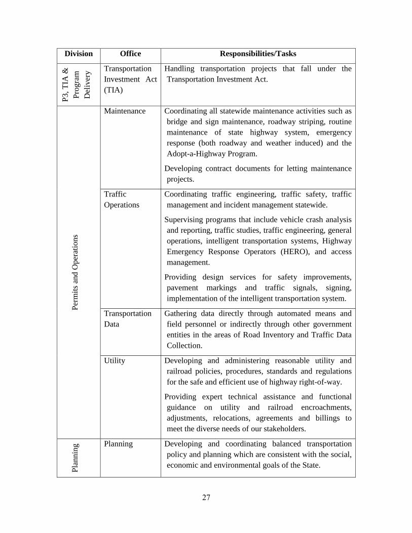
27
Division Office Responsibilities/Tasks
P3, T
IA &
Pro
gra
m
Del
iver
y Transportation
Investment Act
(TIA)
Handling transportation projects that fall under the
Transportation Investment Act. P
erm
its
and O
per
atio
ns
Maintenance Coordinating all statewide maintenance activities such as
bridge and sign maintenance, roadway striping, routine
maintenance of state highway system, emergency
response (both roadway and weather induced) and the
Adopt-a-Highway Program.
Developing contract documents for letting maintenance
projects.
Traffic
Operations
Coordinating traffic engineering, traffic safety, traffic
management and incident management statewide.
Supervising programs that include vehicle crash analysis
and reporting, traffic studies, traffic engineering, general
operations, intelligent transportation systems, Highway
Emergency Response Operators (HERO), and access
management.
Providing design services for safety improvements,
pavement markings and traffic signals, signing,
implementation of the intelligent transportation system.
Transportation
Data
Gathering data directly through automated means and
field personnel or indirectly through other government
entities in the areas of Road Inventory and Traffic Data
Collection.
Utility Developing and administering reasonable utility and
railroad policies, procedures, standards and regulations
for the safe and efficient use of highway right-of-way.
Providing expert technical assistance and functional
guidance on utility and railroad encroachments,
adjustments, relocations, agreements and billings to
meet the diverse needs of our stakeholders.
Pla
nnin
g Planning Developing and coordinating balanced transportation
policy and planning which are consistent with the social,
economic and environmental goals of the State.
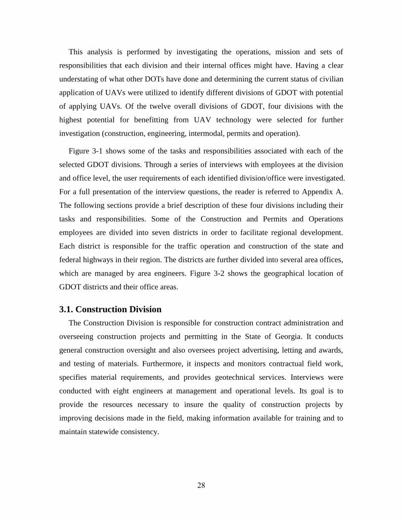
28
This analysis is performed by investigating the operations, mission and sets of
responsibilities that each division and their internal offices might have. Having a clear
understating of what other DOTs have done and determining the current status of civilian
application of UAVs were utilized to identify different divisions of GDOT with potential
of applying UAVs. Of the twelve overall divisions of GDOT, four divisions with the
highest potential for benefitting from UAV technology were selected for further
investigation (construction, engineering, intermodal, permits and operation).
Figure 3-1 shows some of the tasks and responsibilities associated with each of the
selected GDOT divisions. Through a series of interviews with employees at the division
and office level, the user requirements of each identified division/office were investigated.
For a full presentation of the interview questions, the reader is referred to Appendix A.
The following sections provide a brief description of these four divisions including their
tasks and responsibilities. Some of the Construction and Permits and Operations
employees are divided into seven districts in order to facilitate regional development.
Each district is responsible for the traffic operation and construction of the state and
federal highways in their region. The districts are further divided into several area offices,
which are managed by area engineers. Figure 3-2 shows the geographical location of
GDOT districts and their office areas.
3.1. Construction Division
The Construction Division is responsible for construction contract administration and
overseeing construction projects and permitting in the State of Georgia. It conducts
general construction oversight and also oversees project advertising, letting and awards,
and testing of materials. Furthermore, it inspects and monitors contractual field work,
specifies material requirements, and provides geotechnical services. Interviews were
conducted with eight engineers at management and operational levels. Its goal is to
provide the resources necessary to insure the quality of construction projects by
improving decisions made in the field, making information available for training and to
maintain statewide consistency.

29
At the district level, GDOT construction engineers are responsible to oversee, inspect,
and monitor contractual field work. In this regard, they take field measurements of pay
items. The task includes performing several linear, areas, and counting measurements in
the construction site. Moreover, area engineers take field measurements of underground
items (e.g. piping and utilities) during the construction stage. The task includes
performing measurements and documenting for the items underground (e.g. pipes). For
overseeing the work at the construction site, the task includes photo-documentation
(ideally near real-time aerial photography) to see the project overview and also enhancing
the project personnel’s perception of the environment. Thus, they can ensure that projects
are completed on schedule, within budget, and in a way that is safe and follows the
GDOT codes and laws. All data, queries, commands, or responses must be entered into
the GDOT server through a new software program called SiteManager. Information
entered on series of computerized forms is stored in a central database, so when a user
calls up a report or record, the program automatically transfers information from one
form to all other forms and reports that use the same information.
HERO program and
incident
management
Traffic and safety
improvement
Traffic light
maintenance
Gather traffic data
through automated
means or field
personnel
Guide airport
development and
aviation planning
Rail road track
inspection and safety
investigation
Provide planning
assistance to transit
capital projects
Maintain the
navigability of the
waterways
Development of
policies and guidelines
for transit, rail, and
aviation systems
Support engineering
software
Environmental
services to
construction projects
Plan design review and
approval
Development of
construction plans
Development of design
policy and guidelines
Inspect bridges and
culverts
Oversee project
advertising & bidding
Inspect and monitor
contractual field work
Conduct compliance
investigations
Keep track of project
status
Specify material
requirements
GDOT
Construction Engineering Intermodal Permits & Operations
Figure 3-1: GDOT divisions with the highest potential for benefitting from UAV
technology

30
Figure 3-2: GDOT districts – main office and area offices (adopted from GDOT
website, access date: March 2013)

31
This software automates and streamlines the management of highway construction
contracts for everyone involved in the project (SiteManager 2008). To achieve their
important objectives, GDOT construction engineers must communicate with many
individuals at the construction jobsite as well as GDOT people in the office. Eight
interviews were conducted with persons at the district main office and area office levels.
Figure 3-3 shows the organizational chart for construction division and shows how
interviews fit into the organizational chart.
3.2. Engineering Division
The Engineering Division develops environmental studies, right-of-way plans,
construction plans and bid documents through a cooperative effort that results in project
design and implementation. Moreover, the division is responsible for supporting and
maintaining all engineering software, engineering document management, and state wide
mapping. Four interviews were conducted with persons in charge of activities conducted
by the engineering division.
The Engineering division consists of five offices: Environmental Services, Roadway
Design, Bridge Design and Maintenance, Right of Way, and Design Policy and Support.
Office of Environment Services is responsible for obtaining environmental approvals and
all necessary regulatory permits for constructions projects. Roadway Design is
responsible for the development and coordination of conceptual layouts, preliminary and
final construction plans and right-of-way plans of a variety of urban and rural
transportation projects throughout the State of Georgia. The Bridge Design office
oversees the structural design of bridge walls, culverts, sign supports, and anything else
requiring structural expertise. Also this office oversees the hydraulic design of bridge
structures. Bridge maintenance is one of the main activities in the office. This office
inspects all the bridges and bridge culverts in the State (including county bridges) every
two years and evaluates bridges and determines if they must be “load limited.” The
Right-of-Way office reviews process of right of way plans submission and is responsible
for the acquisition of properties necessary for transportation projects. Design Policy and
Support is responsible for supporting and maintaining all engineering software, statewide
plotting, and engineering document management such as design guidelines and standards
adopted by the GDOT for the design of roadways and related infrastructure.

32
Figure 3-3: Organizational chart of GDOT construction division (adopted from GDOT website, access date: March 2013)

33
Considering the roles and responsibilities of the Engineering division, this project only
focuses on “Bridge Design and Maintenance” and “Design Policy and Support” offices.
GDOT bridge maintenance employees are tasked to conduct regularly scheduled routine
inspections of conventional bridges in Georgia. The goal of this task is to determine the
physical and functional condition of a bridge and to identify changes compared to
previous inspections. Furthermore, these routine inspections are to ensure that a bridge
continues to satisfy all applicable serviceability requirements. A Routine inspection is a
regularly scheduled inspection to determine the physical and functional condition of a
bridge and to identify any changes since previous inspections. These inspections are
generally conducted from deck level, ground or water levels, or from permanent-access
structures. An In-Depth inspection is a close-up, hands-on inspection of one or more
members to identify deficiencies not normally detected during routine inspections. These
types of inspections are generally completed at longer intervals than Routine inspections
and may include the use of more advanced nondestructive examination techniques. A
Specialized inspection is completed to assess structural damage resulting from
environmental or human actions. The scope of each specialized inspection is unique, with
the general goal of assessing the need for further action. Special inspections could also be
warranted for complex bridge structures (major river bridges, movable, suspension, cable
stayed, and other bridges with unusual characteristics) or inspections of underwater parts
of a bridge.
Design Policy and Support is responsible for supporting and enhancing all aspects of
program delivery through developing and maintaining Design Policy, Guidelines, and
Standards and providing Engineering Technical Support. The GDOT Design Policy and
Support office has recent and historical aerial imagery of the entire state of Georgia to
assist in the design of highways and other transportation improvements. There is a need
for aerial photography at conceptual and engineering level (i.e. elevation dependent). The
task includes managing an archive of aerial photography procured by GDOT and other
cooperating agencies. Figure 3-4 shows the organizational structure for the engineering
division (only offices of interests to the present study are shown). Five interviews were
conducted with personnel at management and operational levels.

34
3.3. Intermodal Division
The main responsibility of the Intermodal Division is to support and facilitate the
development and implementation of intermodal policies, planning, and projects in the
highway program and organize all major statewide non-highway programs for the
development of a comprehensive transportation system. The intermodal division consists
of four main programs: (1) aviation programs is tasked to guide airport development and
to assure a safe and well-maintained system of public-use airports; (2) transit programs
provide transit capital and operating assistance to the urban and all metropolitan planning
organizations in Georgia; (3) rail programs include track inspection and safety
investigation for the Georgia rail system in cooperation with the Federal Railroad
Administration; (4) waterways programs maintain the navigability of the Atlantic
Intracoastal waterway and Georgia's deep water ports in Savannah and Brunswick.
Consequently, five interviews were conducted with members from the intermodal
division, including at least one interviewee from each of the above programs.
The condition of airports is assessed by the Intermodal division through field
investigation. The aviation program is responsible for airport investigation for
compliance with relevant Georgia codes as well as the collection of data for federal
agencies (mainly through the form "5010"), including assessing the location of trees,
Figure 3-4: Organizational chart of GDOT engineering division (adopted from GDOT
website, access date: March 2013)

35
airport and runway geometry, lighting and wildlife and bird control/monitoring. The
transit program provides funding to support urban areas in planning, developing, and
improving public transportation systems and Federal resources to urbanized areas and for
transit capital and operating assistance in urbanized areas (population of 50,000 or more)
and for transportation-related planning. The railroad program includes track inspection
and safety investigation in cooperation with the Federal Railroad Administration and
preservation of railroad corridors for current and future use. The task includes having
near real-time (aerial) photography that provides an overview of the railroads and also
allows for assessing environmental conditions. The Port of Savannah handles 80% of the
ship-borne cargo entering Georgia. The GDOT (waterways program in particular) is the
local sponsor for the Savannah Harbor and is responsible for: (1) Providing easements
and rights-of-way for upland disposal areas, and (2) Providing 35% of the cost required
to raise the dikes at the upland disposal areas in the Savannah Harbor. The task includes
conducting field surveys to determine the current height and capacity of disposal areas.
Also, the GDOT waterways program is responsible to monitor wildlife along the
intercostal waterways, such as monitoring bird nesting activities and all the nests located
in flood-prone areas. Figure 3-5 shows the organizational chart for intermodal division.
Figure 3-5: Organizational chart of GDOT intermodal division (adopted from GDOT
website, access date: March 2013)

36
3.4. Permits and Operations Division
The Permits and Operations Division ensures a safe and efficient transportation system
by collecting traffic data, addressing maintenance needs (e.g. related to traffic lights) and
regulating the proper use of the state highway system. In order to improve traffic flow
and coordinate traffic engineering, traffic safety, and incident management statewide, the
division collects traffic data (e.g. flow, speed, counts) using a wide range of devices (e.g.
video cameras, microwave sensors, and computer applications pertaining to traffic
services). This division consists of four offices: Transportation Data, Utilities, Traffic
Operations, and Maintenance.
The office of traffic operations is collecting traffic data (e.g. flow, speed, counts) using
surveillance video cameras (i.e. permanent traffic data collection devices), traffic
counting device (i.e. microwave sensors), and INRIX traffic app. Road closure, traffic
detours and special events are supervised through daily coordination with the traffic
operation office. The task includes having real-time traffic data in the case of special
events (e.g. hurricane and evacuation) to choose the best way to detour or evacuate the
traffic, or during an incident (for people at the scene). Most accidents require one or more
individuals to investigate its circumstances to see how it happened, who caused it, and
how it could have been avoided. Many times the facts discovered in the investigation will
be pertinent to a claim by the injured party for damages and relevant to future settlement
negotiations or a civil trial to assess fault and damages. Thus, this office is responsible for
the investigation of accident scenes and mapping the area (e.g. location of signs) and
topography.
In order to assess intersections, GDOT traffic operations personnel at district level use
turning movement counters to quantify the movement of vehicles through the area.
Turning movement counts represents the various approach movements (left and right
thru) that pass through an intersection over a given period of time. They are collected for
a variety of purposes at signalized and un-signalized intersections. Furthermore, traffic
signal maintenance and repair issues are the common concerns experienced by the office
of maintenance. The ownership and maintenance responsibilities for all traffic signal
devices erected on the State Route System are described by GDOT prior to their
installation. A typical traffic signal installation costs around $150,000, and has an annual

37
maintenance and power costs of about $5,000. Interviews were conducted with seven
engineers at management, district and area office levels. Figure 3-6 shows the
organizational chart for permits and operations division and shows how interviews fit into
the organizational chart.

38
Figure 3-6: Organizational chart of GDOT permits and operations division (adopted from GDOT website, access date: March
2013)

39
4. CHAPTER IV
4. Identification of Operational Requirements
The operational requirements incorporated into the study were taken from a series of
interviews with employees at the division and office level from four divisions
(construction, engineering, intermodal, and permits and operations). Of the twenty four
experts that were interviewed, eight were construction employees, four were in charge of
activities conducted by the engineering division, five were intermodal employees, and
seven were permits and operations employees. These experts were chosen because of
their knowledge of and their experiences with activities and operations related to each
identified GDOT division and/or offices. In order to determine the operational
requirements for UAS usage for a specific division that could benefit from such
technology, a user-centered top-down approach was chosen. In this user focused
approach, the overall tasks and user requirements are categorized into various functions
and components, enabling a comprehensive understanding of users’ goals, their working
environment, and decision-making processes.
The data sample comprised of 24 GDOT employees in the major fields of construction,
engineering, intermodal and traffic operations who volunteered to participate in the study.
Prior to the interview, all participants were required to give informed consent which
explains to an individual who volunteers to participate in the study, the goals, processes,
and risks involved. Therefore, each participant was presented with an Informed Consent
Form for him or her to read in agreement to participate in the study. The university’s
Institutional Review Board (IRB) evaluated and approved the study protocol. The
approved consent form is presented in Appendix B. The demographic characteristics
include gender, age, years of experience, education level, and whether the participant
used UAS for any application etc. Table 4-1 presents a summary of the major
demographic characteristics of the participants in the study.

40
Table 4-1: Demographic and work-related statistics of participants
Variable Percentage Variable Percentage
Gender (N=24) Age (N=22)
Male 79 20-29 15
Female 21 30-39 35
40-49 40
50 < 10
Size of department (N=22)
1-3 people 14 Highest degree attained (N=24)
3-10 people 32 High school diploma 18
10-50 people 46 Associate's degree 9
50-100 people 4 Bachelor 64
More than100 people 4 Master 9
Work experience (total)
(N=24)
Work experience (GDOT)
(N=24)
0-5 years 14 0-5 years 23
5-10 years 23 5-10 years 17
10-20 years 36 10-20 years 46
20-30 years 23 20-30 years 14
30 < years 4 30 < years 0
Based upon the investigations conducted at the various divisions and offices within
GDOT (Chapter III), the user requirements for specific divisions that have the potential to
implement UAS technology are identified in this chapter. Therefore, a set of UAS design
characteristics that fulfill user requirements of each previously identified division is
determined.
The selected approach consists of four different considerations, as shown in Figure 4-
1: (1) defining the operational tasks in the division, (2) studying the environmental
conditions of operational workplace, (3) analyzing the user characteristics, and (4)
investigating the current technologies and tools used in the division’s operations.
Interview guides containing five sets of questions were prepared beforehand for
collecting data for each consideration and for an evaluation of potential applications of
UAS technology in the interviewee’s area of expertise.

41
4.1. Defining the Operational Tasks in the Division
The first consideration is to define the tasks and operations performed in the identified
division. A semi-structured interview format was chosen to develop exact definitions of
those tasks and to expand their scope. The questions of this step are related to the basic
goals of the operators, their major decisions for accomplishing those goals, and the
information requirements for each decision. This step has resulted in identifying more
than 40 tasks that could benefit from the implementation of UAS technology. The
majority of the tasks are centered around collecting data, providing information, and
decision making based on the data. Examples of the tasks for each division are given in
Table 4.2. Currently most of the related data are collected through field personnel.
Table 4-2: Examples of the tasks performed by each GDOT division
Division Task Description Duration Frequency
Const
ruct
ion
GDOT construction engineers take field
measurements of contractual items. The task
includes performing several linear, areas, and
counting measurements in the construction site.
2-3 Hrs. several
times per
week
For overseeing the work at the construction site,
the task includes having near real-time (aerial)
photography to see the project overview and also
enhancing the project personnel’s perception of
the environment.
N/A several
times per
week
Defining the
operational tasks in the
division
Analyzing the user
characteristics
Studying the
environmental conditions
of the workplace
Investigating the current
technologies/tools used at
division’s operations
Developing a
detail user
requirement chart
Validating the
resulted chart with
real users
Figure 4-1: User requirements identification workflow

42
Division Task Description Duration Frequency
Const
ruct
ion
GDOT construction engineers take field
measurements of underground piping and
utilities. The task includes performing
measurements and documenting the items
underground (e.g. pipes).
N/A several
times per
month
It is GDOT construction engineers' responsibility
to make sure projects are completed on schedule,
within budget, and in a way that is safe and
follows the GDOT codes and laws. The task
includes having an overview of the project.
N/A several
times per
month
All data, queries, commands, or responses must
be entered into the GDOT server through some
sort of interface (e.g. SiteManager software). The
task includes entering the field data into GDOT
computer systems.
N/A several
times per
week
The task includes measuring spread rate of
concrete and asphalt while inspecting a
construction job site. This is necessary for
invoicing and quality control.
2-3 Hrs. several
times per
week
GDOT construction engineers must communicate
with many individuals, including contractors, and
GDOT people in the office. The task includes
communicating to the GDOT people involved in
a project from the construction jobsite.
N/A several
times per
week
GDOT construction engineers use soil
compaction measuring devices (e.g. nuclear gauge
testing) to check and measure soil compaction.
15-30
minutes
several
times per
year
GDOT construction engineers take field
measurements of concrete and earthmoving
activities. The task includes measuring the
concrete poured (or earthwork) for construction
cubic yards (or cubic feet).
30-60
minutes
several
times per
week
GDOT construction engineers are responsible to
ensure proper execution of erosion control. The
task includes documenting erosion control
measures in an accurate and timely fashion.
N/A several
times per
year

43
Division Task Description Duration Frequency
Engin
eeri
ng
The GDOT Design Policy and Support Division
has recent and historical aerial imagery of the
entire state of Georgia to assist in the design of
highways and other transportation improvements.
There is a need for aerial photography at
conceptual and engineering level (i.e. elevation
dependent).
Also, in order to avoid tampering and for
litigation prevention the GDOT needs to collect
existing condition of catastrophic crashes and
destruction data quickly. The task includes
managing archive of aerial photography procured
by GDOT and other cooperating agencies.
N/A several
times per
year
In general, Archeological and Environmental Site
Assessments are conducted in response to the
federal laws. In this process, there are some
supportive information such as historical aerial
photographs, and photographic logs. The task
includes taking aerial photography for
environmental or archeological assessments.
N/A annually
The GDOT Bridge Inspection Engineers are
responsible for the inspection of all bridges and
bridge culverts within a two year cycle. In
addition, GDOT construction engineers are
responsible to inspect the bridge (e.g. bridge
foundation, beams) during construction.
N/A several
times per
week
Routine Simple Bridge Inspection: A Routine
Inspection is a regularly scheduled inspection to
determine the physical and functional condition
of a bridge and to identify any changes since
previous inspections.
Furthermore, Routine Inspections serve to ensure
a bridge continues to satisfy all applicable
serviceability requirements. These inspections are
generally conducted from deck level, ground or
water levels, or from permanent-access structures.
30-60
minutes
several
times per
week

44
Division Task Description Duration Frequency
Engin
eeri
ng
In-Depth Bridge Inspection: This is a close-up,
hands-on inspection of one or more members to
identify deficiencies not normally detected during
Routine Inspections. They are generally
completed at longer intervals than Routine
Inspections and may include the use of more
advanced Non-destructive testing techniques.
1-2 Hrs. several
times per
month
Specialized Bridge Inspection: A Specialized
Inspection is completed to assess structural
damage resulting from environmental or human
actions. The scope of each Damage Inspection is
unique, with the general goal of assessing the
need for further action. Special inspections could
also be warranted for complex bridge structures
(major river bridges, movable, suspension, cable
stayed, and other bridges with unusual
characteristics) or inspections of underwater parts
of a bridge.
2-3 Hrs. several
times per
year
Inte
rmodal
The conditions of airports are assessed by the
Aviation Program through field investigation.
Airport investigations for compliance with
relevant GA codes as well as the collection of
data for federal agencies, including assessing the
location of trees, airport and runway geometry,
lighting and wildlife and bird control/monitoring.
The tasks includes inspecting airports and their
surrounding areas, identifying obstructions and
determining the geometry of the runway
3-4 Hrs. several
times per
month
The Port of Savannah handles 80% of the ship-
borne cargo entering Georgia. The Waterways
Program is the local sponsor for the Savannah
Harbor and is responsible for: (1) Providing
easements and rights-of-way for upland disposal
areas, and (2) Providing 35% of the cost required
raising the dikes at the upland disposal areas in
the Savannah Harbor. The task includes
conducting field surveys to determine the existing
height and capacity of disposal areas.
2-3 Hrs. several
times per
year

45
Division Task Description Duration Frequency
Inte
rmodal
The Waterways Program is the local sponsor for
the Savannah Harbor and is responsible to help
wildlife along the intercostal waterways. The task
includes monitoring birds' nesting, keep and put
some bird's islands in the areas of flooded and
then count the number of birds
N/A several
times per
month
The Railroad Program includes railroad track
inspections and safety investigations in
cooperation with the Federal Railroad
Administration and preservation of railroad
corridors for current and future use. The task
includes having near real-time (aerial)
photography to see the railroads overview and
also check the environment.
N/A several
times per
month
Rail Program Engineers must communicate with
many individuals, including contractors, and
GDOT personnel in the office. The task includes
communicating with GDOT personnel involved
in a project from the construction jobsite.
15-30
minutes
several
times per
month
Per
mit
s an
d O
per
atio
ns
In order to coordinate traffic engineering, traffic
safety, traffic management and incident
management statewide, the task includes
collecting traffic data (e.g. flow, speed, counts)
using surveillance video cameras (i.e. permanent
traffic data collection devices), traffic counting
device (i.e. microwave sensors), and INRIX
traffic app.
1-2 Hrs. several
times per
week
The main roads in the State affected by special
events and/or accidents. Road closure, traffic
detours and special events are supervised through
daily coordination with the traffic operation
division. The task includes having real-time
traffic data in the case of special events (e.g.
hurricane and evacuation) to choose the best way
to detour or evacuate the traffic, or during an
incident (for people in the scene).
1-2 Hrs. several
times per
month

46
Division Task Description Duration Frequency
Per
mit
s an
d O
per
atio
ns
Most accidents require one or more individuals to
investigate its circumstances to see how it
happened, who caused it, and how it could have
been avoided. Many times the facts discovered in
the investigation will be pertinent to a claim by
the injured party for damages and relevant to
future settlement negotiations or a civil trial to
assess fault and damages. The task includes the
investigation of accident scenes and mapping the
area (e.g. location of signs) and topography.
15-30
minutes
several
times per
month
Traffic signal maintenance and repair issues are
the common concerns experienced by GDOT.
The ownership and maintenance responsibilities
for all traffic signal devices erected on the State
Route System are described by GDOT prior to
their installation. A typical traffic signal
installation costs around $150,000, and has an
annual maintenance and power costs of about
$5,000. The task includes providing traffic signal
maintenance or checks the traffic signals.
15-30
minutes
several
times per
week
The HERO unit's primary purpose is to minimize
traffic congestion by clearing wrecked or disabled
vehicles from the roadway lanes and providing
traffic control at incident scenes. In the case of
accident, the task includes clearing the accident
scene and re-opens the lane.
30-60
minutes
several
times per
week
The traffic operations uses traffic counts to
identify which routes are used most, and to either
improve that road or provide an alternative if
there is an excessive amount of traffic. A traffic
count is a count of traffic along a particular road,
either done electronically or by people counting
by the side of the road. The task includes
measuring traffic counts (as well as speed
sample).
2-3 Hrs. several
times per
month

47
Division Task Description Duration Frequency
Per
mit
s an
d O
per
atio
ns
The task includes monitoring the traffic and
counting the number of cars, as well as speed
control. By conducting site visits, GDOT traffic
operations staffs at district level monitor traffic
conditions, and may use real-time (i.e. live) view
of situations from varying directions.
2-3 Hrs. several
times per
month
In order to assess intersections, GDOT traffic
operations personnel at district level use turning
movement counters to quantify the movement of
vehicles through the area. Turning movement
counts, which represent the various approach
movements (left, thru, right) that pass through an
intersection over a given period of time, are
collected for a variety of purposes at signalized
and un-signalized intersections. The task includes
the assessment of intersections using turning
movement counters.
1-2 Hrs. several
times per
month
The traffic operations office reviews driveway
permits and road changes. Purpose of driveway,
entrance and property characteristics, exact
location of present and proposed driveway are
common information for the review process.
Therefore, the task includes field assessment in
order to review driveway permits or road changes
(e.g. adding an access).
1-2 Hrs. several
times per
month
4.2. Studying the Environmental Conditions of the Workplace
Another important consideration that should be taken into account is the
environmental conditions, in which the tasks are performed. These environmental
conditions affect the design requirements for a UAS. Ambient noise levels, lighting levels,
susceptibility to weather and temperature variations, vibration, privacy, expected pace of
operations, position of use (e.g. sitting, standing, while mobile), and frequency of use (e.g.
occasional, intermittent, frequent, continuous) are some issues that should be considered
(Endsley 2003). Each task is also characterized by some attributes that yield a better
understanding of the environmental conditions including locations where the tasks are

48
performed. A local task occurs at one location or a job site that can be best described as a
patch of land where the primary descriptor would be the length and width of the area. A
distributed task occurs on a strip of land (i.e. along a road, a river, or a railway), or any
other place where the primary descriptor would be a length or distance. The size of the
task area (or task area dimension) is defined as the range of physical features or facilities
in the workplace, which provides a means to directly compare the dimension and physical
characteristics of different task. The span of task area dimension ranges from 100 yards
in the small workplaces to over 10 miles in some large size workspaces. The time
required to complete a given task is determined by the duration of the task and the
frequency of the task occurrence (see Table 4-2).
4.3. Analyzing the User Characteristics
The third consideration is to identify user characteristics such as gender, skill level
(e.g. familiarity with basic computer features), training, background knowledge
(including technical capability), age ranges (with special note of young or aging
populations), and languages to be accommodated. Other user characteristics related to
special clothing also appear to have a significant effect on performance. Thus, it is also
desirable to take the type of special clothing of the user into consideration. Gloves, masks,
backpacks, and any personal protective equipment are examples of clothing items that
can be used while working. Upon completion of an interview, the team convened to
review the interview notes. During the team debriefing, key quotes and trends were
extracted alongside summary of the interview. The summaries were in turn used to derive
user characteristics across user demographics and interviews.
4.4. Investigating the Current Tools/Technologies Used in Division’s
Operations
Then, as the last consideration, all different technologies or tools being used by the
identified division’s personnel should be evaluated for possible integration with the UAV
platform. There might be a need for integrating hardware (e.g. sensors, radars, or
different type of cameras) with the UAV hardware or software. Additionally, the user
interface might be required to incorporate or be compatible with other technologies that
are currently used by GDOT in the identified division (e.g. asset management or traffic
software). Based on the records and interviews, the study team created a list of tools used

49
while performing the identified tasks. The tools (and technology) used by the GDOT
personnel can be classified under eight categories: Measuring equipment are used in
various linear, areas, and counting measurements. Examples include measuring wheel
and tape, distance meter, air meters, scoops, and thermometer. Surveying equipment (e.g.
theodolite, total station, GPS devices, etc.) are used to produce accurate maps and
dimensions of the site. Engineering software tools are used to collect and process
observation data from the workplace. The most important example is “Site Manager”
software that is used by construction office. Computer hardware, specialized software,
and communication devices are used together to collect, analyze, and transmit data
collection and communication processes. Basic hand tools and digital cameras are
frequently used by GDOT employees traveling out-of-office. Finally, many of the tasks
performed by the division of permits and traffic operations require vehicle detection and
mobile application tools. Examples include traffic counter, radar gun, range finder, and
turning movement counter.
Figure 4-2 shows the result operational requirement matrix that includes each
division’s operation, user characteristics, working environment, and technology use. The
frequency of occurrence is calculated based upon the number of tasks performed in each
division. To identify missing information and errors in the matrix and validate its
outcomes, this matrix was then taken back to the subject matter experts who were
interviewed. All of the information was validated through feedback of the interviewees
(see Appendix C). The feedback was collected and further analyzed to minimize apparent
similarities between the identified tasks. As a result, 19 main tasks were selected as the
tasks with the greatest potential use of UAV in the near term. For convenience, the list of
all the validated tasks in this stage is reported in Appendix D. The foundation for
identifying the technical requirements towards a UAV to be used within GDOT stems
from the collected response data.

50
4.5. Identification of Technical Requirements
The details of the technical requirements for performing the identified tasks are
discussed in the next chapter. How certain aspects of the identified tasks contribute to the
UAV technical requirement is discussed here. Figure 4-3 shows the created UAV
requirement matrix for the identified divisions within GDOT; the left part is pertaining to
the notion of UAV classes, while the right part shows the sensor suites. Based upon the
task classification of being either local or distributed, the related primary descriptor (a
length or an area, respectively), and the task attributes duration and frequency, the
identified tasks can be binned. Skipping questions related to the control station(s) and the
necessary human machine interface for the moment, several classes of potentially
utilizable UAVs can be created and associated with these task bins. Once these classes
have been established, combining them with a sensor and/or actuator suite provides a
particular UAS capable of aiding a particular set of tasks. The combination of the class
and sensor suite descriptors then provide the technical requirements for a system used in
Figure 4-2: Operational requirements matrix

51
all the tasks that fall into the class related bin and have data collection needs fulfillable by
the particular sensor suite.
A major discriminator in classifying UAVs is whether the vehicle is a fixed wing
system (e.g. an airplane), or a rotary wing system (e.g. a helicopter). The sizing of the
vehicle is then driven by the required payload capacity in the context of the airframe
choice. For the most part, it can be assumed that payload can be divided among carried
fuel and sensors (and/or other devices) required for the task. The fuel requirement of a
specific task can be related to the primary descriptor, used as a notion for the required
operational range, and to a certain degree, the task duration, as a notion for the required
operational endurance. Using the airframe choice, the range requirement can then be
transformed into an additional endurance requirement based upon different nominal
cruise speeds of fixed wing and rotary wing systems. Based on the chosen binning, the
UAV classes can then be picked in the continuous endurance/payload/size design space.
At this point, it could also be decided whether a particular class should have the potential
to trade fuel for sensors, for example through a modular sensor rack.
Sensor and other device requirements, the other main component making up the
required payload, can also be extracted from the created operational requirements list.
Unfortunately, there is no direct one-to-one correspondence between the list of tools
utilized (by a human) and the required set of sensors for the UAV. However, having an
Figure 4-3: Technical requirements matrix
52
understanding of the underlying data collection requirements of the tasks on the one hand
and selecting from variable options to collect that data with a UAV on the other, opens up
the potential for multi-use of installed sensors. Multi-use can lead to a reduced number of
installed sensors and an overall expansion of the data collection capabilities of a
particular UAV sensor suite. Of special interest in this context are sensors that could be
considered “free” as they are already required for the operation of the UAS. Examples are
global navigation satellite system sensors (e.g. GPS), inertial measurement units, or
cameras, which, when combined with sufficient computational power and a suitable
navigation solution, could harness the potential of geo-referenced pictures. A collection
of several different sensors, multi-use and specialized, into sensor suites provides another
set of discriminators for building the technology requirements matrix.
Depending on the characteristics of the chosen classes and the sensors, not all possible
combinations of UAV classes with sensor suites are possible. One limiting factor is mass
(installed sensors vs. carried fuel), and another one is power consumption (sensor runtime
vs. vehicle endurance). A possible combination of a class with a sensor suite provides the
largest part of the technical requirements for a UAV that should be suitable to aid all
tasks that are in the corresponding class and sensor suite bins.
To complete the set of technical requirements, several other aspects have to be taken
into account. Depending on the UAV class, there might be the option for either an
electric or gasoline powered system. The collected task frequency data could provide
some guidance for specifying power system, for example through limitations on recharge
time or the number of spare battery packs that can be utilized. Additionally, the frequency
could give a hint whether a system could be shared among users or whether several
systems are required to fulfill the needs of all users. Several other technical requirements
can be associated with the control station. The major group of requirements in this
section can be related to the operation of the system. The level of autonomy can vary
from just slightly augmented tele-operation within the line of sight of the operator to
point-and-click interfaces through which centralized UAS users could interact remotely
with the system.
Another group of requirements associated to the control station is a set of basic
questions about the human machine interface; for smaller ad-hoc deployable systems,

53
issues are related to things such as operability with gloves, outdoor readability, ingress
protection ratings, or actual usability of the underlying software. For larger systems
requirements also focus on requirements related to the utilized data links, for example
availability, bandwidth, lag, and security. An additional aspect for all systems is the
amount of required training a current performer of the task would need to utilize the UAS
aid. Furthermore, requirements also arise from needed backend interfaces of the UAS to
other potential software systems which the operator has to feed the collected data.
54
5. CHAPTER V
5.1. Analysis of UAS Requirements
This section details the transition process from the validated data collected in the
interviews to a set of five reference UAS systems which could be used to support GDOT
operations.
5.1.1. Introduction
In line with the goal of this study to create a higher level understanding of the
potential use of UAS by GDOT, the research team has focused the UAS specific analysis
on the operational aspects of UAS use across GDOT divisions and the requirements
resulting from that. In an effort to capture system specific interconnections, an adoption
of the viewgraph type “House of Quality” (HoQ) has been chosen to capture the relations
between GDOT tasks and potential UAS aiding those. The process leading to the creating
of the HoQ is depicted in Figure 5-1.
Based upon the validated data resulting from the interview process (see Chapter IV),
the researchers used their expertise to group tasks based upon a “best fit” to potential
UAS. The process entailed an assignment of GDOT tasks to UAV airframe categories
through an iterative process: initially the categories where based on commercial-of-the-
shelf (COTS) airframe options, but throughout the iterations of modifying the airframe
and reassigning the tasks, some changes included non-COTS components to better match
apparent GDOT needs.
The resulting reference systems – five systems have been identified – are represented
in the HoQ in the Technical Requirements section, above which the Correlations section
captures some of the design correlations among the technical requirements. The validated
data is represented in the HoQ in the Operator Requirements section and tries to capture
the most pertinent requirements of GDOT with respect to the use of UAS.

55
5.1.2. UAS Technical Requirements
Part of the iterative process leading to the reference systems is the identification of
technical requirements for the UAS. These requirements, which are correlated with each
other (see Chapter IV), try to capture design requirements for certain aspects of the
identified tasks.
For the analysis, a UAS is broken into three components: Vehicle, Control Station,
and System. The Vehicle section groups requirements for the UAV, which are mainly
airframe hardware related requirements. The section Control Station groups requirements
for hard- and software for the control station utilized by the UAS operator, however, the
software considered is related to the graphical user interface (GUI) of the interface and
does not include specific guidance, navigation, and control (GNC) aspects. Those
requirements are grouped into the System section, which mainly contains capability
features of the reference systems. To further simplify, the three categories could be seen
as primarily representing the hardware aspects of the UAV (Vehicle), the control station
and human machine interface used by the operator (Control Station), and the algorithmic
features the GNC and other specialized software provides (System).
Vehicle Requirements
Airframe Ruggedness: Airframe ruggedness tries to capture the overall “sturdiness” of
the UAV. A rugged airframe can on one side better deal with in-flight collisions (at slow
speeds), for example, an inadvertent bump into a wall, and on the other side withstand a
Figure 5-1: House of Quality creation process

56
rougher handling, for example, when placed in a trunk or a truck bed. Ruggedness also
can include protection from the elements, for example, rain or dust.
Airframe Availability: Airframe availability is one major factor in the overall
availability of the UAV, which in essence consists of the airframe, the avionics (the
“autopilot”), and the payload1 (i.e. sensors). If the avionics are modular enough, it could
be sufficient to instrument a readily available COTS R/C airframe. This could allow for
cheaper maintenance as spare parts should be readily available and, depending on the
configuration, alternates from other manufacturers might be substituted.
However, the drawback of COTS airframes could be an extended integration time, as the
airframes might not easily accommodate the avionics or the payload.
Custom build airframes could provide a better performance, but the lead time and per unit
cost could be higher than for adapted COTS airframes.
Endurance: Endurance is an abstract high level requirement that tries to capture the
technical aspects of available operational time. Endurance for airframes is mainly driven
by the chosen aircraft category (for example, a rotary or fixed wing vehicle) and the size.
In general, airplanes have a longer endurance than rotary wing aircraft and larger aircraft
have a longer endurance than smaller ones; however, the overall UAV endurance is
dependent on a lot more factors than the aircraft category and the size.
Actuated Video Camera: The requirement for an actuated video camera is a fairly
specific need, which requires a video sensor of the airframe to be moveable. The
actuation could be in any or all of the three axis of motion, roll, pitch, and yaw, and could
either be automated or externally driven. A use of an automated video camera could be in
first-person video (FPV) flight, where automation would use the actuation to compensate
for the attitude changes of the airframe, comparable to how an onboard pilot would move
her head while piloting a full size aircraft. Alternatively, the actuation could be used to
steer the video sensor towards a point of interest while the airframe remains stationary
(for vehicle capable of hovering flight) or loitering (for all others), comparable to the
1 Payload – UAV onboard equipment, most often sensors, that are necessary to complete a task but which
are not strictly necessary for autonomous UAV flight. Note, however, that data gathered through payload
sensors can benefit the overall GNC performance.
57
controls to conventional pan/tilt camera turrets, for example, the cameras used for
GDOT’s Navigator program.
Actuated Non-Video Sensor Package: The requirement for an actuated non-sensor
package captures the need to steer other payload sensors, potentially independent of the
video source. This could be used, for example, to scan the airframe surroundings for
potential collision hazards or to expand a sensing frustum.
Telepresence: Certain identified tasks require establishing communication with people
in the vicinity of the aircraft. Telepresence should at least encompass a voice
communication feature, which is in the presence of a speaker and a microphone of sorts.
Depending on the situation, the addition of a visual presence can be beneficial,
effectively establishing a rudimentary video conferencing capability.
Manipulator and/or Effector: The telepresence can be taken to the next step through
the addition of manipulator arms or other effectors. Their presence in an airframe could
allow an operator to conduct tasks that normally would have to be done by a human (e.g.
pressing buttons or moving objects). Effectors could range from simple grappling hooks
to fully articulate and very dexterous robotic arms.
Control Station Requirements
Interactive Object Selection and Identification: This requirement relates to the GUI of
the control station and requests a simple interface to directly interact with video coming
from the UAV. The operator should be able to simply interact with the system through
clicking, dragging, or drawing onto the video, enabling the operator to, for example,
determine the next waypoint, move the vehicle, or determine a segment of a road for
further inspection.
Ruggedness: Just like the airframe, the control station hardware will be used outdoors,
potentially in harsh conditions such as the construction site. Ruggedness for a control
station also includes the “sturdiness” of the hardware, for example, protection against
damage from drops, water spills, or dust. Ruggedness also includes the ability to operate
the control station while wearing personal protective gear appropriate for the location,
such as gloves, hearing protection, or glasses. Ruggedness also includes the use of
58
appropriate connectors where necessary, for example, for charging, interfacing with other
computers, or necessary local infrastructure, for example external antennas.
Portability: Portability covers the requirement to easily transport the control station.
Depending on the task or system at hand, this not only includes the portability of the
operator interface, but the entire infrastructure comprising the control station, potentially
including a (tablet) computer, external data link or GPS antennas, and potentially power
sources.
System Requirements
Sense and Avoid: Sense and avoid is the UAS realization of the “See and Avoid”
principle for flight under Visual Flight Rules (VFR). Sense and avoid allows a UAS to
detect cooperative as well as non-cooperative traffic in the vicinity of the aircraft and
conduct evasive maneuvers if a collision might be imminent. Sense and avoid can be
extended to include stationary obstacles as well, essentially allowing a UAS to navigate
an area with potentially unknown obstacles.
Waypoint Navigation: Waypoint navigation allows a UAS to follow a flight plan
through the means to waypoints. Waypoints, most likely given through GPS coordinates,
are ordered in a certain sequence which the UAS will follow. They could also capture
certain maneuvers such as “landing” or “hovering”.
Kinematically Constrained Operations: Conventionally UAVs are assumed to move
freely through space, constrained solemnly through their dynamic limitations (aircraft,
unlike helicopters, for example, normally can’t move “backwards”). Kinematically
constrained operations further restrict the possible motion through physical means.
Examples include flying while tethered to a power source through a flexible cable, flying
while connected to a rigid structure, or flying while docking (i.e. physically attaching to a
connector).
Unattended Deployment and Return: The requirement for unattended deployment and
return imposes the requirement for automatic take-off and landing without the presence
of an external pilot within the line of sight of the landing or take-off site.
High-precision Navigation: Autonomous flight most of the time relies on the presence
and availability of a GNSS (e.g. GPS). The accuracy of a navigation solution (i.e. the
59
system internal estimation of the current location of the aircraft) is to a large degree
governed by the accuracy achievable with the utilized GNSS; for GPS this could be as
good as several meters for non-aided systems and potentially down into the centimeter
range when differential GPS systems are used. High precision navigation poses the
requirement to achieve a navigation solution that is comparable to the accuracy
achievable through the use of ground surveying methods (e.g. total station equipment).
Simultaneous Location and Mapping: Simultaneous location and mapping (SLAM)
describes the capability of a system to navigate through a priori unknown environment
while building a map of that environment – which is simultaneously used to navigate in
the (known portions) of the environment. SLAM generally requires the presence of
sensors which can accurately capture the environment (a prominent choice being a Light
Detection and Ranging system (LiDAR)), as well as a considerable amount of
computational power to process the sensor data. It can also be used to navigate with
respect to a priori available data, for example, the plans of a building under construction,
which then is matched to the current sensing of the environment.
Advanced Data-link and Networking: The requirement for advanced data-link and
networking features captures the need for Radio Frequency (R/F) communication
capabilities beyond a simple point-to-point link between the UAV and its control station.
Examples for advanced networking could include the use of external networks in which
both, the UAV and the control station, are clients (for example, using a corporate large
scale Wi-Fi network), or the creating of other mobile ad-hoc networks (MANETs).
MANETs could be either relying on external infrastructure or they could be completely
independent, meaning that all involved networking nodes (i.e. UAVs and control stations)
would span the network. Advanced data-link requirements could be certain security
measures, validation of received data, or special requirements towards the involved R/F
hardware, for example, special bands, modulations, antennas, etc.
Sensor Data Abstraction and Reduction: With an increase in payload sensors comes
an inevitable increase in available raw sensor data. In an effort to offload UAS operators
from data interpretation tasks, this requirement captures the need for the system to
automatically process raw sensor data and only provide the (abstract) result to the
operator. An example for this could be an iconographic representation of an item that the

60
system is tasked to identify. Instead of overloading the operator with the raw sensor data
(e.g. the raw 3D point cloud of a LiDAR), the system only provides its findings,
potentially with a confidence margin (e.g. a simple line drawing representing a wall).
Vision Based Data Extraction: Vision based data extraction captures the request for
any kind of computer vision based algorithm like pattern recognition, optical flow, or
feature point based processes. These could allow, in combination with the navigation
solution from the UAV and camera calibration data, to generate 3D coordinates of
(feature) points, based upon the stereo-from-motion principles. Vision based
augmentation systems can also be used to augment the navigation solution in areas with
limited GNSS availability.
5.1.3. Intra-system Correlations
The correlations part of the House of Quality viewgraph presents a rough and
simplified overview of the interplay between and among the selected technical
requirements for the reference systems’ Vehicle, Control Station, and System sections
(see Figure 5-2). The figure indicates the high independence of the Control Station
section from the Vehicle section as nearly no correlations are identified. This stipulates
that future research could treat these two units independently and that both parts could be
specifically tailored to the actual need at hand while allowing reusing of previous
technology. The correlation between the Control Station and the System sections is a
little stronger, indicating that the UAS operator primarily interacts with the UAS on a
system level as opposed to a pilot level; the later would be comparable, for example, to
radio controlled flight of a model airplane. A strong correlation between the System and
Vehicle sections is expected, as System essentially represents (GNC software)
capabilities which require the presence of certain features in Vehicle. Additional
information for the individual correlations can be found in Appendix G, which lists a
brief rationale for each correlation.

61
Improvements
"More/Higher" is better
Nominal value
"Less/Fewer" is better
Control Station System
Airframe Payload Capabilities GUI Hardware
Airf
ram
e Ru
gged
ness
Airf
ram
e Av
aila
bilit
y
Endu
ranc
e
Actu
ated
Vid
eo C
amer
a
Actu
ated
Non
-Vid
eo S
enso
r
Pack
age
Vehicle
Sens
or D
ata
Abst
ract
ion
and
Redu
ctio
n
Visi
on B
ased
Dat
a Ex
trac
tion
Way
poin
t Nav
igat
ion
Kine
mat
ical
ly c
onst
rain
ed
oper
atio
ns
Una
tten
ded
depl
oym
ent a
nd
retu
rn
Hig
h-pr
ecis
ion
navi
gatio
n
Sim
ulta
neou
s Lo
catio
n an
d
Map
ping
(SLA
M)
Adva
nced
Dat
alin
k an
d
Net
wor
king
Tele
pres
ence
Man
ipul
ator
and
/or E
ffec
tor
Inte
ract
ive
Obj
ect S
elec
tion
and
Iden
tific
atio
n
Rugg
edne
ss
Port
abili
ty
Sens
e an
d Av
oid
Strong Positive
Correlations
Positive
Negative
Strong Negative
Figure 5-2: The correlations part of the House of Quality showing the interplay between the technical requirements

62
5.1.4. Operator Requirements
First-Person Video (FPV) Operation
First-Person Video operation describes a mode of piloting an aircraft in which an
external pilot controls an aircraft while using a live video feed from a perspective that
mimics a pilot’s position. FPV operations, particularly in combination with stability
augmentation systems2 (SAS), can simplify the piloting of an aircraft as the overall setup
is comparable to many computer or console games. However, depending on the FPV
setup, the overall situational awareness (SA) of the pilot can be reduced due to the limits
of the visible environment. This is especially notable during take-off and landing when
the aircraft is within the line of sight of the operator and the operator could control the
aircraft from a third-person perspective which allows capturing the overall representation
of the aircraft within its environment. Overly simplifying, FPV operations are
comparable to first-person video games and have the benefit of a relatively low
requirement for autonomous operations as a pilot, the operator, is always in the control
loop of the vehicle.
Non-FPV Operation
Non-FPV operations describe control schemes in which the operator never directly
assumes the role of an external pilot, but controls the UAV on a very high system level,
most likely through the use of waypoints. For example, a non-FPV operation could be the
creating of a flight plan on a map, uploading that flight plan to the system and executing
it. The operator interacts with the system comparable to the way how air traffic control
(ATC) can interact with a general aviation airplane: issuing holding patterns, rerouting it,
requesting climbs and descends, etc.
Pilot-independent sensor package control
Pilot independent sensor package control replicates a work load sharing comparable to
a two pilot cockpit: a pilot-flying (PF; be it a human operator or automation) and a pilot-
non-flying (PNF), who is responsible for the systems. This arrangement allows the PF to
2 Stability Augmentation Systems; a piloting aid which considerably lessens the workload of a pilot through
augmenting the pilot’s control inputs.

63
focus on piloting, e.g. complying with ATC directions or avoiding other aircraft and
obstacles, while the PNF can focus on utilizing the payload sensors to collect the data
required.
Use at construction site
This requirement captures UAS operations under the environmental conditions present
at a construction site: outdoors, in the presence of semi-structured dirty environments and
heavy machinery, and generally rather “rough.” It also encompasses the operation over
and among workers present on the site and as such poses the requirement to be safely
operable among cooperative3 people.
Use at traffic signal site
The use at traffic signal site is comparable to the use at a construction site, however
several significant differences exist. Traffic signal sites pose a special collision hazard
through the presence of comparatively small obstacles (e.g. wires, small trusses, sign or
light posts). Furthermore, the presence of non-cooperative4
traffic and people as well as
the extended accident possibility as a result of system failures pose special safety
requirements.
Metro-area range/coverage
The UAS should be able to operate throughout the Atlanta metro area, which is an
area of roughly 400 square miles. This poses a requirement to the airframe for endurance
and, to a certain extent, speed, as well as on the R/F system utilized to communicate with
the UAV. The utilized data-link could, for example, either be a long range point-to-point
data-link, a setup incorporating several interconnected smaller ground based broadcast
stations, or a swarm based MANET.
3 The term cooperative in this context is meant to describe that people in the vicinity of the UAV are
cooperating with the UAS in the sense of being made aware of its operations (and correspondingly looking
out for it), as well as being asked to engage in certain safety measures, for example, wearing a hard hat and
safety glasses. Cooperating people are also assumed to know who controls the UAV and hence are able to
voice warnings or concerns to the operator. 4 Non-cooperative are all people in the vicinity of the UAV that are not among the cooperative people (as
stated above), like pedestrians or motorists. These people might not be aware of the UAV operations, its
intentions, and whom to address with safety concerns.

64
Get point coordinates
The operator should be able to get geo-referenced 3D coordinates of a point or feature
shown on the video feed from the UAV. (See the related task description in Appendix E.)
Measure site dimensions
The operator should be able to measure linear distances between points identified on
the video feed of the UAV, get elevations of them, and obtain a reasonable estimate for
any polygonal area determined by a sequence of identified points. (See the related task
description in Appendix E.)
Estimate volumes
The operator should be able to utilize the system to get estimates for volumes, for
example of earth work on a construction site. (See the related task description in
Appendix E.)
Create digital elevation model
Using the UAS, the operator should be able to create a digital elevation model of the
terrain with an accuracy sufficient for the task context, i.e. lower for earth volume
estimates, higher for survey situation, and comparable to the accuracy currently achieved
without UAS aid.
Count/track/detect items
The operator should be able to mark items on a map and later get their location and
count. (See the related task description in Appendix E.)
Precise navigation
The position accuracy of the UAS navigation solution should be good enough to
operate the UAV in close presence to obstacles without a dedicated need of sensing them.
For example, the operator should be able to maneuver the UAV close to such an obstacle,
let go of any controls, and the vehicle should be able to maintain its position within some
epsilon ball small enough to not collide with the obstacle (if the vehicle is capable of
hovering).

65
Provides survey-quality data
The navigation solution of the UAS should be good enough so that provided
coordinates for features sensed by the system have a quality comparable to a
conventional survey performed, for example, with a total station.
Correlate sensor data to plans/drawings
The operator should be able to overlay digital plans or drawings with the video feed
coming from the UAV to correlate both data sets. Also, if SLAM is available, the system
should be able to include digital plans and drawings into the SLAM map to provide
measurements relative to those plans and drawings.
"Line-of-sight" clearance measurements
The UAS should be able to determine its attitude well enough to create a line of site
measurement and identify either a clear line of sight or the presence of obstacles.
Collect floating traffic samples
The system should be able to track a vehicle identified by the operator through normal
traffic and extract data pertinent to that vehicle from the systems navigation solution and
the video data. Data of interest would be, for example, speed, acceleration, or distance
traveled.
Allows triggering a "reset"
The UAV is equipped with a mechanism to trigger a (electro-) mechanical reset
function on a cooperative device.
Interact with inspected element
The UAV is capable to manipulate an element in its close vicinity, either through an
manipulator or effector or through “bumping” into the element. Interaction also includes
the use of certain measurement or probing devices with the element under inspection.
66
Establish contact to people
The UAS can be utilized to establish a two-way conversation between people present
at the location of the UAV and the operator or any other third party connected to the UAS’
communication link.
Eliminate need for human task execution
The UAS is capable of performing all tasks a human would do during a certain task.
These requirements established the need to be able to complete or perform a task
previously executed by a human remotely, preferably by that same human as an expert
operator.
Conduct traffic counts
The UAS can conduct a set of traffic counts for a given location. This includes simple
counts, turning movement counts, speed samples, and throughput measurements. (See the
related task description in Appendix E.)
Data on demand
The UAS can be utilized in a manner in which the operator is agnostic of the
underlying system or the actual physical operations necessary to obtain the requested data.
An example of such an operation could be a first response coordinators request for live
video of a certain location within the coverage area of the UAS.
5.2. Reference Systems
Based upon the reviewed data, five reference systems are proposed. These systems
capture the majority of the tasks identified through the interview process and cover a
wide spectrum of capabilities, expandability, but also availability. This chapter describes
the proposed systems. Although the presented systems are described in certain detail,
none of them are fully evaluated for feasibility, performance, or optimality of any kind.
As such, the described systems are meant to simply describe a potentially possible setup
that could be used for certain identified tasks and provide a basis for further in depth
studies.

67
5.2.1. Commonalities
The presented system descriptions put an emphasis on the air vehicles and the
associated (hardware) infrastructure, focusing on sensing and data acquisition. The
system-level capabilities that provide use to GDOT most likely stem from processing this
acquired data. Active research is currently conducted in many of the related fields and
thus the reference system descriptions do not provide detail on those algorithms but
simply assume their availability.
In accordance to the correlations between the UAV, the control station and the
operator, all reference systems are assumed to provide a level of autonomy comparable to
that reached by GUST (Georgia Tech UAV Simulation Tool). GUST provides a level of
autonomy that allows operators with minimal or no radio controlled (R/C) experience to
fly a UAV as the operator interacts with the UAV on a system level and not on a pilot
level. For example, this allows for a “computer game”-like joystick interface which
decouples the actual flight dynamics from the joystick input: stick forward is simply
“forward flight” and not as in R/C flight, for example for airplanes, elevator deflection
down.
5.2.2. System A – Flying Camera
The air unit of System A, the Flying Camera, provides the most basic functionality of
placing a (video) camera anywhere in the accessible space and streaming live video to the
operator (see Figure 5-3)..
Usage Scenario:
The Flying Camera could be used in any situation where a video or picture is all that is
needed as a data input. The operator would simply start the system, use FPV to frame the
picture or video needed, record the images and finish the task at hand. The data post
processing could be as simple as storing the resulting still photo or video sequence or
interacting with the live video feed from the UAV.

68
Airframe:
The airframe for System A would need to be VTOL capable, fairly robust, and safe to
be used around people, for example a small scale quad rotor with shrouded propellers.
The benefit of a quad rotor over a conventional helicopter would be the reduced
mechanical complexity and hopefully a resulting increase in robustness.
Payload:
System A would most likely not carry any special payload beside a video camera.
Actuating the camera could improve the performance, so, in order to maintain a high
level of robustness, a virtual camera tilting could be implemented through several small
scale cameras. The setup could provide a low resolution feed and, upon operator request,
high(er) definition onboard video recording or still photography.
Control Station:
The control station would be primarily focused on ruggedness and portability. A first
implementation could be a based on a tablet computer, utilizing on-screen virtual controls,
with the potential to expand the setup with a dedicated game pad style controller or a pair
of video goggles for improved FPV operation. If goggles are used, the GUI interface of
the tablet based control station software would need to be adapted to be compatible to the
utilized controller.
Required Infrastructure:
No special infrastructure is necessary to operate System A. However, there is the need
for training, maintenance, and recharging, which needs to be organized. As the system
presumably would be small enough to be transported in a protective case in a car’s trunk
or pickup bed, no special transport equipment should be needed.
Capabilities:
The systems capabilities would mainly rely on computer vision based algorithms
performed off board (i.e. with a transmission time delay) and only with the limited
computational power available in a tablet.
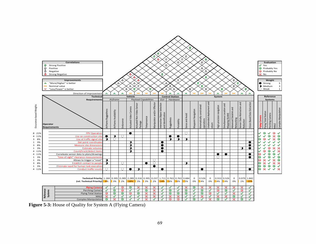
69
Figure 5-3: House of Quality for System A (Flying Camera)
Flyi
ng C
amer
a
Flyi
ng T
otal
Sta
tion
Perc
hing
Cam
era
MAL
E
Com
plex
Man
ipul
atio
n
8 21% FPV Operation
4 11% Use on construction site
3 8% Use at traffic signal site
1 3% Get point coordinates
3 8% Measure site dimensions
1 3% Estimate volumes
4 11% Count/track/detect items
4 11% Correleate sensor data to plans/drawings
1 3% "Line-of-sight" clearance measurements
1 3% Allows to trigger a "reset"
3 8% Establish contact to people
1 3% Eliminate need for human task execution
4 11% Conduct traffic counts
Technical Priority
(rel. Technical Priority)
Flying Camera
Perching Camera
Flying Total Station
MALE
Complex Manipulation
Evaluation
Strong Positive
Correlations
Yes
Positive Probably Yes
Negative Probably No
Strong Negative No
Improvements Weight
"More/Higher" is better 5Strong
Nominal value 3
"Less/Fewer" is better
MediumWeak 1
Direction of Improvement
Control Station System Reference
SystemsAirframe Payload Capabilities GUI Hardware
Operator
Requirements Airf
ram
e Ru
gged
ness
Airf
ram
e Av
aila
bilit
y
Endu
ranc
e
Actu
ated
Vid
eo C
amer
a
Actu
ated
Non
-Vid
eo S
enso
r
Pack
age
Occ
uran
ce-b
ased
Wei
ghts
Technical
Requirements
Vehicle
Sens
or D
ata
Abst
ract
ion
and
Redu
ctio
n
Visi
on B
ased
Dat
a Ex
trac
tion
Way
poin
t Nav
igat
ion
Kine
mat
ical
ly c
onst
rain
ed
oper
atio
ns
Una
tten
ded
depl
oym
ent a
nd
retu
rn
Hig
h-pr
ecis
ion
navi
gatio
n
Sim
ulta
neou
s Lo
catio
n an
d
Map
ping
(SLA
M)
Adva
nced
Dat
alin
k an
d
Net
wor
king
Tele
pres
ence
Man
ipul
ator
and
/or E
ffec
tor
Inte
ract
ive
Obj
ect S
elec
tion
and
Iden
tific
atio
n
Rugg
edne
ss
Port
abili
ty
Sens
e an
d Av
oid
1.184 0.395 0.289 2.289 0.316 0.079 1.8420.526 0 0.553 0.526 000.395 0.237 1.711 0.763 0.763 0.684
4% 4% 0% 1% 15%6% 6% 5% 0% 4% 0%9% 3% 2% 18% 3% 3% 2% 14%
Refe
renc
e
Syst
ems

70
5.2.3. System B – Flying Total Station
System B expands upon System A by providing higher quality measurements of the
environment. The main focus of the system is to act as a flying total station, i.e. perform
tasks similar to the ones done by a survey crew, but faster, especially in otherwise
unprepared environments. As the systems’ expected operational radius is limited, the
UAV could be tethered to a power outlet at the control station site (see Figure 5-4).
Usage Scenario:
The flying total station could be used anytime survey data or location data of survey
quality is needed. The system could be brought on scene, maneuvered to the area to be
surveyed (either through FPV video or conventional third person flying), and the survey
could be started. Post processing would presumably be similar to post-processing regular
total station data.
Airframe:
System B would need an airframe that is capable of prolonged hover operations,
precise positioning, and a certain level of failure tolerance to protect against the loss of
potentially expensive sensors. These requirements would point towards a multi copter
which is designed for redundancy. This could be a hexa- or octocopter which is sized so
that not all rotors are needed to stay airborne. As people, both cooperative as well as non-
cooperative, would presumably negatively impact the survey process by blocking line of
sight, it can be assumed that the system would be operated in the presence of relatively
few cooperative people, as such reducing the requirements for safety through shrouds, etc.
Payload:
The system would presumably carry LiDAR equipment to replicate a total station.
Additionally, altimeter, for example sonar or laser based, could be used to establish a
correct above ground altitude and in reverse determine the elevation of the terrain.
Additional onboard computational power might be required to process the LiDAR data.

71
Figure 5-4: House of Quality for System B (Flying Total Station)
Flyi
ng C
amer
a
Flyi
ng T
otal
Sta
tion
Perc
hing
Cam
era
MAL
E
Com
plex
Man
ipul
atio
n
8 21% FPV Operation
1 3% Non-FPV Operation
4 11% Use on construction site
3 8% Use at traffic signal site
1 3% Get point coordinates
3 8% Measure site dimensions
1 3% Estimate volumes
2 5% Create digital elevation model
4 11% Count/track/detect items
4 11% Precise navigation
1 3% Provides survey-quality data
4 11% Correleate sensor data to plans/drawings
1 3% "Line-of-sight" clearance measurements
1 3% Eliminate need for human task execution
Technical Priority
(rel. Technical Priority)
Flying Camera
Flying Total Station
Perching Camera
MALE
Complex Manipulation
Evaluation
Strong Positive
Correlations
Yes
Positive Probably Yes
Negative Probably No
Strong Negative No
Improvements Weight
"More/Higher" is better 5Strong
Nominal value 3
"Less/Fewer" is better
MediumWeak 1
Direction of Improvement
Control Station System Reference
SystemsAirframe Payload Capabilities GUI Hardware
Operator
Requirements Airf
ram
e Ru
gged
ness
Airf
ram
e Av
aila
bilit
y
Endu
ranc
e
Actu
ated
Vid
eo C
amer
a
Actu
ated
Non
-Vid
eo S
enso
r
Pack
age
Occ
uran
ce-b
ased
Wei
ghts
Technical
Requirements
Vehicle
Sens
or D
ata
Abst
ract
ion
and
Redu
ctio
n
Visi
on B
ased
Dat
a Ex
trac
tion
Way
poin
t Nav
igat
ion
Kine
mat
ical
ly c
onst
rain
ed
oper
atio
ns
Una
tten
ded
depl
oym
ent a
nd
retu
rn
Hig
h-pr
ecis
ion
navi
gatio
n
Sim
ulta
neou
s Lo
catio
n an
d
Map
ping
(SLA
M)
Adva
nced
Dat
alin
k an
d
Net
wor
king
Tele
pres
ence
Man
ipul
ator
and
/or E
ffec
tor
Inte
ract
ive
Obj
ect S
elec
tion
and
Iden
tific
atio
n
Rugg
edne
ss
Port
abili
ty
Sens
e an
d Av
oid
0.763 0.395 0.105 1.763 0.579 0.237 1.4740 0.132 1.211 1.237 0.0790.4470 0.132 1.184 0.763 0.763 0.579
10% 10% 1% 2% 12%6% 6% 5% 4% 0% 1%6% 3% 1% 15% 5% 0% 1% 10%
Refe
renc
e
Syst
ems
72
Control Station:
The control station for System B would most likely be comprised of a powerful
ruggedized laptop as well as a GNSS reference station to establish a differential
correction for the navigation solution.
Required Infrastructure:
System B would not need any special communications landing site infrastructure to be
operated. However, due to the size of the UAV as well as the additional antennas for the
control station, the system most likely would be comprised of some larger crates (to be
transportable by pickup or SUV). An alternative would be a dedicated trailer or van. (For
more details on dedicated vehicles, see Section 5.2.6, the infrastructure requirements for
System E.)
Capabilities:
The increased computation power both on- as well as offboard would allow the system
to not only utilize vision to detect and identify objects, but also to process video data in
combination with the LiDAR data to perform SLAM-based high precision navigation.
Furthermore, the system should be able to allow working with digital plans and drawings,
for example to check the correct location of construction features, roadway markings, or
property boundaries.
5.2.4. System C – Perching Camera
System C is also expands upon System A, but mainly focusing on a prolonged
capturing of the environment. Based upon that, operational endurance is a main
application goal of System B. This could either be achieved through highly efficient
flight, which might be hard to achieve given that a considerable amount of that flight time
could be hover or hover-like operations, or it could be achieved through perching (see
Figure 5-5).
Usage Scenario:
Due to the pertinent standby capability perching provides, System C could mainly be
used in two modes: as an ad-hoc deployed UAS for local, on-site inspection or
measurement tasks, or as a deployed-on-demand system. The former usage is comparable

73
to that of System A. The later usage would imply that System C UAVs have strategically
located fixed “base stations,” which would serve as recharging stations and potentially as
communication towers. A user requiring services provided by System C would use a
control station, request a UAV, and be given control over the closes available air unit.
Once the operator doesn’t need the services any longer, the UAV would be released and
return to a base station.
Airframe:
As a result from the perching requirement, the airframe is required to be relatively
small to be able to get to potential perching locations as well as being robust to
inadvertent collisions close to the selected perching location. Furthermore, the airframe
needs to be equipped with a landing gear of sorts to facilitate perching on poles, or traffic
signal installations. These requirements could be realized with a smaller scale hexa-
copter or potentially a small electric conventional helicopter.
Required Infrastructure:
The perching capability recommends System C for an extended dual use: one the one
hand as a mobile UAS with the described capabilities, on the other hand as a static
continuously operating camera. A potential scenario could be the deployment of several
dedicated perching locations which could double as a charging or refueling station. If the
System C units then provide a MANET capability, System C units could, for example,
replace the conventional Navigator cameras installed throughout the Atlanta metro area.
Resulting from that, a set of permanent perching locations are needed. These base
stations would provide recharging capabilities, allow easy access for maintenance, and
could also double as R/F communication outlets spanning the MANET utilized by
System C.

74
Figure 5-5: House of Quality for System C (Perching Camera)
Flyi
ng C
amer
a
Flyi
ng T
otal
Sta
tion
Perc
hing
Cam
era
MAL
E
Com
plex
Man
ipul
atio
n
8 14% FPV Operation
1 2% Non-FPV Operation
3 5% Pilot-independet sensor package control
4 7% Use on construction site
3 5% Use at traffic signal site
5 9% Metro-area range/coverage
1 2% Get point coordinates
3 5% Measure site dimensions
1 2% Estimate volumes
4 7% Count/track/detect items
4 7% Correleate sensor data to plans/drawings
1 2% "Line-of-sight" clearance measurements
4 7% Collect floating traffic samples
1 2% Allows to trigger a "reset"
4 7% Interact with inspected element
3 5% Establish contact to people
1 2% Eliminate need for human task execution
4 7% Conduct traffic counts
2 4% Data on demand
Technical Priority
(rel. Technical Priority)
Flying Camera
Flying Total Station
Perching Camera
MALE
Complex Manipulation
Evaluation
Strong Positive
Correlations
Yes
Positive Probably Yes
Negative Probably No
Strong Negative No
Improvements Weight
"More/Higher" is better 5Strong
Nominal value 3
"Less/Fewer" is better
MediumWeak 1
Direction of Improvement
Control Station System Reference
SystemsAirframe Payload Capabilities GUI Hardware
Operator
Requirements Airfr
ame
Rugg
edne
ss
Airfr
ame
Avai
labi
lity
Endu
ranc
e
Actu
ated
Vid
eo C
amer
a
Actu
ated
Non
-Vid
eo S
enso
r
Pack
age
Occu
ranc
e-ba
sed
Wei
ghts
Technical
Requirements
Vehicle
Sens
or D
ata
Abst
ract
ion
and
Redu
ctio
n
Visio
n Ba
sed
Data
Ext
ract
ion
Way
poin
t Nav
igat
ion
Kine
mat
ically
cons
trai
ned
oper
atio
ns
Unat
tend
ed d
eplo
ymen
t and
retu
rn
High
-pre
cisio
n na
viga
tion
Sim
ulta
neou
s Loc
atio
n an
d
Map
ping
(SLA
M)
Adva
nced
Dat
alin
k an
d
Netw
orki
ng
Tele
pres
ence
Man
ipul
ator
and
/or E
ffect
or
Inte
ract
ive
Obje
ct S
elec
tion
and
Iden
tifica
tion
Rugg
edne
ss
Port
abili
ty
Sens
e an
d Av
oid
1.211 0.263 0.702 1.789 0.474 0.053 1.5790.702 0.298 0.368 0.351 0.8070.4390.263 0.509 1.14 0.509 0.509 0.895
3% 3% 6% 0% 12%4% 4% 7% 3% 5% 2%9% 2% 5% 14% 4% 2% 4% 9%
Refe
renc
e
Syst
ems

75
Payload:
Given that perching could limit the achievable attitudes while landed, actuated video
and non-video sensor packages are presumably necessary to compensate for that. Given
the use cases for System C, it seems likely that the system would also provide
telepresence equipment as well as advanced networking capabilities.
Control Station:
The control stations for System C could be of several types. Given the potential use
cases, operators should be able to use control stations tailored to them and their particular
needs: HERO personnel, for example, could utilize a rugged tablet computer based
system comparable to a unit used to control System A; GDOT employees working in the
Traffic Control Center could use a software that operates on their desktop computers;
traffic engineering and traffic management personnel could use a laptop.
The control station would provide a FPV interface and a graphical tool for waypoint
navigation as well as indicating measurement areas or regions of interest.
Capabilities:
System C would mainly provide vision based capabilities, potentially making use of
dedicated external computation centers to support limited computation power available in
tablet based control stations. The system would expand upon the capabilities of System A,
especially toward traffic related tasks.
5.2.5. System D – Medium Altitude, Long Endurance (MALE)
Whereas the proposed Systems A through C could be classified as having a local
operational area, System D is designed to expand this to a regional scale. The UAV
would allow long operational usage throughout a county-sized area. The system separates
the piloting tasks from the payload operation and data acquisition tasks, allowing for a
very high level of operator interaction (see Figure 5-6).

76
Figure 5-6: House of Quality for System D (MALE)
Flyi
ng C
amer
a
Flyi
ng T
otal
Sta
tion
Perc
hing
Cam
era
MAL
E
Com
plex
Man
ipul
atio
n
8 18% FPV Operation
1 2% Non-FPV Operation
3 7% Pilot-independet sensor package control
5 11% Metro-area range/coverage
1 2% Get point coordinates
3 7% Measure site dimensions
2 5% Create digital elevation model
4 9% Count/track/detect items
1 2% Provides survey-quality data
4 9% Correleate sensor data to plans/drawings
1 2% "Line-of-sight" clearance measurements
4 9% Collect floating traffic samples
1 2% Eliminate need for human task execution
4 9% Conduct traffic counts
2 5% Data on demand
Technical Priority
(rel. Technical Priority)
Flying Camera
Flying Total Station
Perching Camera
MALE
Complex Manipulation
Evaluation
Strong Positive
Correlations
Yes
Positive Probably Yes
Negative Probably No
Strong Negative No
Improvements Weight
"More/Higher" is better 5Strong
Nominal value 3
"Less/Fewer" is better
MediumWeak 1
Direction of Improvement
Control Station System Reference
SystemsAirframe Payload Capabilities GUI Hardware
Operator
Requirements Airfr
ame
Rugg
edne
ss
Airfr
ame
Avai
labi
lity
Endu
ranc
e
Actu
ated
Vid
eo C
amer
a
Actu
ated
Non
-Vid
eo S
enso
r
Pack
age
Occ
uran
ce-b
ased
Wei
ghts
Technical
Requirements
Vehicle
Sens
or D
ata
Abst
ract
ion
and
Redu
ctio
n
Visio
n Ba
sed
Data
Ext
ract
ion
Way
poin
t Nav
igat
ion
Kine
mat
ically
cons
trai
ned
oper
atio
ns
Unat
tend
ed d
eplo
ymen
t and
retu
rn
High
-pre
cisio
n na
viga
tion
Sim
ulta
neou
s Loc
atio
n an
d
Map
ping
(SLA
M)
Adva
nced
Dat
alin
k an
d
Netw
orki
ng
Tele
pres
ence
Man
ipul
ator
and
/or E
ffect
or
Inte
ract
ive
Obj
ect S
elec
tion
and
Iden
tifica
tion
Rugg
edne
ss
Port
abili
ty
Sens
e an
d Av
oid
0.364 0 0.75 2.25 0.841 0.136 2.0680.455 0.386 0.591 0.795 1.0450.5680 0.114 1.364 0 0 0.75
5% 6% 8% 1% 17%0% 0% 6% 5% 4% 3%3% 0% 6% 18% 7% 0% 1% 11%
Refe
renc
e
Syst
ems

77
Usage Scenario:
System D could operate in two ways, comparable to System C. In the ad-hoc mode,
the UAV would be stationed at an airfield and would get airborne as soon as an operator
requests control over a system. In the data-on-demand scenario, the air unit(s) of System
C would loiter over a dedicated operational area in a low energy standby mode. Once an
operator requests data, the system would relocate to the specific area requested and start
to operate its payload sensors.
Airframe:
The airframe of choice for System D would most likely be a fixed wing aircraft design,
sized somewhere in the 2 m to 6 m wingspan regimen. The airframe would provide all
mandated general aviation equipment, for example, aviation band radios, a transponder,
and most likely an Automatic dependent surveillance-broadcast (ADS-B) transceiver, as
the system would have to operate within the (controlled) national airspace, among other
general aviation traffic.
Payload:
The system would primarily provide a calibrated pan/tilt/zoom video sensor to provide
high quality aerial photography. The system could augment this with ground scanning
LiDAR systems and directional antennas for advanced networking features. Further
sensor equipment could include microwave based systems to detect traffic movements or
near and far infrared systems to aid in the localization of stranded motorists at night or
the detection of wild fires. Further optional payload capabilities could include R/F relay
stations for first responder disaster response communication systems.
Control Station:
The control station for System D would most likely be consisting of several
independent units. One of them would be the payload focused unit available to the
payload focused operators. Related to that would be a highly portable data display unit,
available to first responders on site, which could be used to access the data provided from
the system. Separate from that would be a control station for an external pilot which
would aid the system during taxi, take-off, and landing operations as well as serve as a
voice relay when conversing with ATC.

78
Required Infrastructure:
System D would require an airstrip for take-off and landing. Given that the system
should need much smaller take-off and landing distanced, operation out of a general
aviation (GA) airport is not necessary and a dedicated airstrip might mitigate a lot of
integration into GA ground operations. If a dedicated airstrip is chosen, external pilots for
take-off and landing aiding could also have better access to the runway strip.
As the system should provide longer range operations, ground communication stations
with dedicated directional antennas might be necessary and could also be located at the
utilized airstrip. Furthermore, maintenance and refueling opportunities need to be
provided.
Capabilities:
System D would primarily provide aerial photographic and video data, which would
satisfy the quality requirements of photogrammetric applications. The payload operator
could also make live feeds of the video data available to first responders or HERO units.
System D could also be used as a disaster response communication relay station in case
conventional ground based infrastructure would not be available.
System D could also provide Navigator like traffic sensing capabilities, which could
allow temporary traffic data capturing during larger events outside the conventionally
covered areas.
5.2.6. System E – Complex Manipulation
An example for this category: This most likely would be a custom made multi-rotor
with 8 or more rotors or an even more special “inverted” helicopter, where the main rotor
sits below most of the airframe. The multi-rotor configuration or the low main rotor
configuration would most likely be necessary to allow an tele-robotics style manipulator
to act above the rotor disc(s), as this most likely would be safest for working under
bridges. The system would be transported in a dedicated van/truck and could potentially
be tethered to allow for prolonged operations in hover and/or while powering the
manipulator. The system would most likely have an external (safety) pilot as we well as a
remote operator (in the van/truck) (see Figure 5-7).

79
Figure 5-7: House of Quality for System E (Complex Manipulation)
Flyi
ng C
amer
a
Flyi
ng T
otal
Sta
tion
Perc
hing
Cam
era
MAL
E
Com
plex
Man
ipul
atio
n
8 22% FPV Operation
3 8% Pilot-independet sensor package control
4 11% Use on construction site
3 8% Use at traffic signal site
1 3% Get point coordinates
3 8% Measure site dimensions
4 11% Precise navigation
4 11% Correleate sensor data to plans/drawings
1 3% "Line-of-sight" clearance measurements
1 3% Allows to trigger a "reset"
4 11% Interact with inspected element
1 3% Eliminate need for human task execution
Technical Priority
(rel. Technical Priority)
Flying Camera
Flying Total Station
Perching Camera
MALE
Complex Manipulation
Evaluation
Strong Positive
Correlations
Yes
Positive Probably Yes
Negative Probably No
Strong Negative No
Improvements Weight
"More/Higher" is better 5Strong
Nominal value 3
"Less/Fewer" is better
MediumWeak 1
Direction of Improvement
Control Station System Reference
SystemsAirframe Payload Capabilities GUI Hardware
Operator
Requirements Airf
ram
e Ru
gged
ness
Airf
ram
e Av
aila
bilit
y
Endu
ranc
e
Actu
ated
Vid
eo C
amer
a
Actu
ated
Non
-Vid
eo S
enso
r
Pack
age
Occ
uran
ce-b
ased
Wei
ghts
Technical
Requirements
Vehicle
Sens
or D
ata
Abst
ract
ion
and
Redu
ctio
n
Visio
n Ba
sed
Data
Ext
ract
ion
Way
poin
t Nav
igat
ion
Kine
mat
ical
ly c
onst
rain
ed
oper
atio
ns
Una
tten
ded
depl
oym
ent a
nd
retu
rn
High
-pre
cisio
n na
viga
tion
Sim
ulta
neou
s Loc
atio
n an
d
Map
ping
(SLA
M)
Adva
nced
Dat
alin
k an
d
Net
wor
king
Tele
pres
ence
Man
ipul
ator
and
/or E
ffect
or
Inte
ract
ive
Obj
ect S
elec
tion
and
Iden
tific
atio
n
Rugg
edne
ss
Port
abili
ty
Sens
e an
d Av
oid
1.189 0.405 0.108 1.811 0.73 0 1.2160.541 0 1.108 0.865 00.3240 0.703 0.541 0.784 0.784 0.459
10% 7% 0% 0% 11%7% 7% 4% 3% 5% 0%10% 4% 1% 16% 6% 0% 6% 5%
Refe
renc
e
Syst
ems

80
System E allows its operators to completely perform a task through telepresence and
tele-robotics in areas that are either complicated or dangerous to access for humans. As
such the focus of the system shifts from a primarily sensing oriented operation to tasks
which include also portions in which previously inspected elements need to be
manipulated.
Usage Scenario:
System E is specifically slanted to be used for bridge or other structural inspection
activities. As such the system would be relocated to the current site under inspection and
the operated on site for the duration of the inspection. The main motivation behind
System E is to replace special access equipment needed during complex inspection tasks
in order to get the human inspector(s) to the inspection site.
The system would presumable be used by at least two operators: a dedicated external
pilot, primarily responsible for piloting the UAV and maneuvering the unit to the
inspection site and a dedicated payload operator who would focus on using the
manipulator and effectors to conduct the actual inspection task. As the later presumably
would need a feedback device to control the manipulator, the payload operator is
assumed to work out of a dedicated control station vehicle, while the pilot operator is
located at a vantage point that provides good situational awareness of the situation the
UAV operates in. Both operators would have voice communication equipment to
coordinate their efforts.
Airframe:
The airframe of System E most likely would have to be a custom designed system. As
the system’s tasks include object manipulation, the airframe has to support a manipulator
or effector of sorts which raises the question of the general geometry of the system. The
airframe would have to be able to hover and provide VTOL capabilities, which would
mean rotors, but also provide a large operational range for the manipulator. A possible
solution could be a large scale multi-rotor where the manipulator is mounted above the
main rotor disk, which allows using the system to be used, for example, under bridges.
Multirotor configurations are preferable for such arrangements as it is easier ti build
airframe structure through the non-rotor occupied center. However, fixing this

81
arrangement would limit the system to tasks in which the manipulator wouldn’t have to
be used below the main rotor discs of the multirotor setup. Switching this to a
conventional helicopter setup with a rotor head configuration that allows for highly
negative pitch angles could, in combination with advanced GNC algorithms, be used to
allow such a system to continuously operate in both orientations: manipulator above the
main rotor as well as below. The airframe furthermore would have to be strong enough to
support not only the manipulator, but also all the forces applied through it. Additionally
several thrusters could be needed to provide pushing or pulling forces without major
changes in the vehicle attitude.
Payload:
The primary payload of System E would be the manipulator or effector and the
supporting telepresence and situational awareness sensors. These could include a stereo
vision rig, a time-of-flight camera or some similar close range 3D sensor, and LiDAR
systems. Additionally the system potentially would have to carry a selection of grappling
interfaces and probing tools.
Control Station:
The control station most likely would also be split into two parts, one more tailored
towards the needs of an external safety pilot, and more tailored towards the needs of the
main payload operator. The former would need to focus on providing the external pilot
with a good situational awareness of the surroundings of the vehicle, later would need to
include a device to control the installed manipulator and request necessary manipulating
forces in addition to the forces needed to maintain flight.
Required Infrastructure:
System E would need a dedicated vehicle. This vehicle would on the one side serve as
the transport vehicle to get the system to the different inspection sites and on the other
side double as the control station once the system is unloaded. The vehicle would provide
a source of power, an indoor workstation for the payload operator, and the required
computer systems. Additionally it would also carry all the other required elements for the
inspection tasks, i.e. any potentially necessary specialized sensors, etc. The vehicle
furthermore would carry traffic control devices to setup and secure the operations.

82
Capabilities:
The system would mainly provide capabilities comparable to a trained human worker
operating out of a bucket truck or a similar reach extending device. To maintain
prolonged operations, the system could be tethered to an external power source and
would need to provide the ability to operate under kinematic constraints, not only from
the tether, but also and especially when latchet onto other objects.

83
6. CHAPTER VI
6. Cost Analysis
The following section contains Rough Order of Magnitude (ROM) cost estimates for
the development, acquisition, and operation of the reference systems described in Chapter
V. These are based on knowledge the authors have about the development of such
systems, information about related existing systems, and by aggregation of lower level
estimates of contributing elements. It is important to point out that this is a rapidly
evolving area, and so estimates made this year could be very different next year or the
year after. There is tremendous uncertainty here, but estimating cost is an exercise worth
doing to support decision-making.
6.1. System A – Flying Camera
There are off-the-shelf systems here that enable perhaps the most accurate cost
estimate for all of the reference systems. Companies with systems for sale today that
could potentially perform this mission are numerous. In fact, hobbyists today are able to
construct similar systems using easily obtainable components. In addition, complete off-
the-shelf systems are available at less than $10,000. It is important to realize that the
lower cost systems are typically not going to be suitable for effective work – given their
limitations in terms of reliability, availability (for example, the weather conditions they
can tolerate) and image quality. A number more like $25,000 is appropriate for a robust
complete turn-key system with ground control equipment, redundant airframes, and
multiple battery packs.
The next important implication of the wide array of existing system is that
development costs here would be minimal. It is probable that an existing system could be
utilized outright. Work within GDOT would largely be around the management,
development on detailed procedures, and training. However, these systems are often quite
simple – and involve training regiments for new users on the order of one day. Future
requirements on UAS operators in general may end up being the primary training driver.
Taken together, an estimate today would be a week for initial training of a new operator
and one day every six months recurring training.

84
6.2. System B – Flying Total Station
Although there are an extremely small number of systems put forth that perform aerial
survey from a UAS, it appears this reference system would require substantial
development to bring to fruition – although with relatively low technical risk. Because of
applications outside of GDOT, it is likely that these development costs could be shared or
included within the platform costs of a product sold more widely. Today, it would take
approximately $1-2M and one year for one of several agile small UAS companies to
transition some of their current work to evolve such a system.
The sensor costs (laser and differential GPS), the necessary system redundancy to go
along with carrying said sensor, and the importance of precision in all aspects of this
reference system result in a substantially more expensive aircraft. Including a likely
dedicated ground vehicle or trailer, a complete system would likely be on the order of
$250,000.
Training for operating the aircraft would be perhaps somewhat more than System A,
but similar. There would likely be entail domain-specific training associated with the
surveying itself and the use of the data. However, at this point it is hard to see how this
aspect would be substantially easier or harder than with existing tools. It would also be
important to provide some minimal training/awareness to those people near the aircraft
when it operates.
6.3. System C – Perching Camera
As an extension of System A, a certain amount of development is necessary to achieve
to perching function and to make the maximum use of it through communication systems.
Although these types of behaviors have been demonstrated in limited flight testing, a
certain amount of technical risk should be associated with an ability to perch a camera in
more than a minority of situations. For example, weather and the conditions of the
immediate surroundings can create real limitations on what can be done at a particular
time in a particular place. Development efforts would seek to minimize these limitations.
This reference system also includes the potential notion of multiple base stations with
multiple aircraft that would need to be maintained as part of a larger network. This is an
area with application beyond GDOT, where it is likely considerable effort will be put
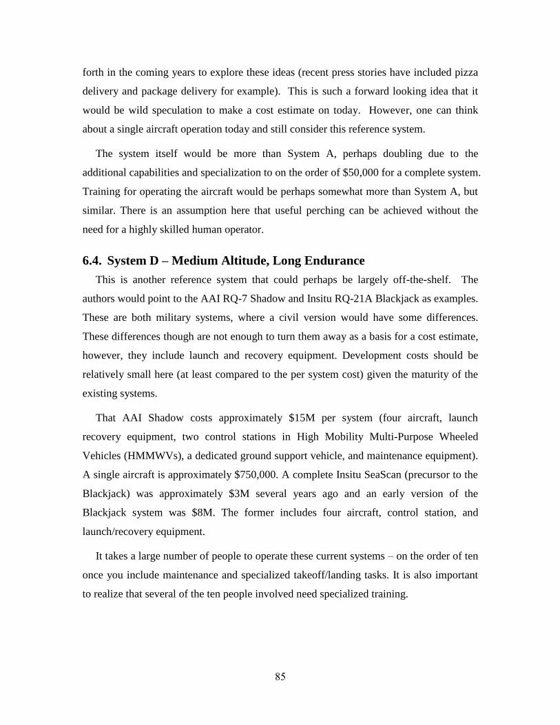
85
forth in the coming years to explore these ideas (recent press stories have included pizza
delivery and package delivery for example). This is such a forward looking idea that it
would be wild speculation to make a cost estimate on today. However, one can think
about a single aircraft operation today and still consider this reference system.
The system itself would be more than System A, perhaps doubling due to the
additional capabilities and specialization to on the order of $50,000 for a complete system.
Training for operating the aircraft would be perhaps somewhat more than System A, but
similar. There is an assumption here that useful perching can be achieved without the
need for a highly skilled human operator.
6.4. System D – Medium Altitude, Long Endurance
This is another reference system that could perhaps be largely off-the-shelf. The
authors would point to the AAI RQ-7 Shadow and Insitu RQ-21A Blackjack as examples.
These are both military systems, where a civil version would have some differences.
These differences though are not enough to turn them away as a basis for a cost estimate,
however, they include launch and recovery equipment. Development costs should be
relatively small here (at least compared to the per system cost) given the maturity of the
existing systems.
That AAI Shadow costs approximately $15M per system (four aircraft, launch
recovery equipment, two control stations in High Mobility Multi-Purpose Wheeled
Vehicles (HMMWVs), a dedicated ground support vehicle, and maintenance equipment).
A single aircraft is approximately $750,000. A complete Insitu SeaScan (precursor to the
Blackjack) was approximately $3M several years ago and an early version of the
Blackjack system was $8M. The former includes four aircraft, control station, and
launch/recovery equipment.
It takes a large number of people to operate these current systems – on the order of ten
once you include maintenance and specialized takeoff/landing tasks. It is also important
to realize that several of the ten people involved need specialized training.

86
6.5. System E – Complex Manipulation
This reference system involves the highest level of technical uncertainty, and so
perhaps the greatest development costs. The closest precedent is perhaps the use of
Unmanned Underwater Vehicles (UUVs) to perform these types of manipulation tasks. A
serious dedicated development effort of more than $5M is likely necessary over several
years to achieve a few of the proposed operational capabilities. However, this is another
domain with applications beyond GDOT, so it is unlikely that GDOT would need to take
on the entire burden of bringing such a capability to fruition.
Once developed, an individual system would likely have cost at least as high as the
most capable bomb disposal robots or similar unmanned underwater vehicles. This would
be on the order of $500,000. It is interesting to speculate that such a system may have
such a wide application beyond GDOT (construction, building maintenance, painting,
disaster response, etc.) that economies of scale could lower this figure substantially.
Operators of such a system would likely be highly skilled and specialized, and include
perhaps three to five dedicated people to support such a system.
6.6. Cost-Benefit Analysis
Part of the research was to attempt a cost-benefit analysis of UAS-aided operations in
selected GDOT divisions, however this turned out as being infeasible within the context
of this research effort as no actual comparison of unaided vs. aided task execution could
be performed.
The semi-structured interviews tried to extract information about a “per task” cost of
the individual task, based upon approximate task durations, publicly accessible salary
information, and estimates about required equipment, etc. The resulting computed
number was returned to the interviewees for validation (compare the “Cost Estimation”
section of the validation form example in Appendix C), but the returned validated data
showed a large spread (the per-task data shown in Appendix D provides an
approximation of the average of all returned data for a particular task), indicating a fair
amount of uncertainty in it.

87
Figure 6-1: Extremely reduced House of Quality for all Systems, also showing estimated
rough order of magnitude cost.
Rough Order of Magnitude
Per-System Cost (which
could be several air units)
Flyi
ng
Cam
era
$ 2
5 k
Flyi
ng
Tota
l Sta
tio
n$
1-2
M
Per
chin
g C
amer
a$
50
k
MA
LE$
75
0 k
- 1
5 M
Co
mp
lex
Man
ipu
lati
on
$ 5
00
k -
5 M
Co
st
Reference
Systems
High-precision navigation
Simultaneous Location and
Mapping (SLAM)
Advanced Datalink and
Networking
Sensor Data Abstraction and
Reduction
Vision Based Data Extraction
Ruggedness
Portability
Sense and Avoid
Waypoint Navigation
Kinematically constrained
operations
Unattended deployment and
return
Air
fra
me
Pa
ylo
ad
Ca
pa
bili
ties
GU
IH
ard
wa
reAirframe Ruggedness
Airframe Availability
Endurance
Actuated Video Camera
Tech
nic
al
Re
qu
ire
me
nts
Ve
hic
leC
on
tro
l Sta
tio
nSy
ste
m
Actuated Non-Video Sensor
Package
Telepresence
Manipulator and/or Effector
Interactive Object Selection
and IdentificationEv
alu
atio
n
Yes
Pro
bab
ly Y
es
Pro
bab
ly N
o
No

88
In addition to the unattainable data showing the cost of the current task execution, the
cost associated with the procurement and operation of the proposed UAS also doesn’t
allow a task or divisions based analysis of a tangible cost benefits for each of the
identified tasks. To elaborate on this, Figure 6-1 shows an extremely reduced version of
the House of Quality viewgraph (Appendix F for the complete viewgraph) combined with
the cost estimates given in Sections 6.1 through 6.5 above. Depending on the System, the
estimated Rough Order of Magnitude (ROM) costs not only capture differences in
hardware costs, for example, a different number of aerial units per system (the Flying
Camera is most likely one UAV per GCS unit, whereas the MALE system has most
likely several UAVs per GCS), but also a wide amount of associated costs resulting from
the use or personnel (the Flying Camera would most likely only involve one person per
executed task – which already omits any personnel required for maintenance and repairs
– whereas the MALE system most likely would require a larger crew to operate a single
aerial unit, at least during certain phases of a task execution). Without more specific
information about those secondary effects, comparable, for example, to the inclusion of
maintaining the vehicle fleet in the cost of the current task execution, it doesn’t seem to
be feasible to come up with any sort of reasonable overhead estimations for the individual
units, yet alone for the individual tasks identified to possibly benefit from UAS utilization.
Without at least some elementary field testing it also seems unlikely to quantify the
intangible benefits of UAS utilization with respect to the cost of the associated systems.
Among the intangible benefits are most certainly an increase in operator safety in all
occasion where a UAS operator can remain on safe ground instead of putting her- or
himself in potentially dangerous locations, for example, during a complex bridge
inspection, an inspection of a traffic signal installation over flowing traffic, or the
measuring and counting of items on a busy construction site or in otherwise undeveloped
pre-construction sites.
This, in combination with the uncertainties in the acquisition and maintenance cost of
the proposed systems as well as no validated operational description of UAS-aided task
executions, led the researchers to stop the attempt to create a cost benefit analysis.

89
7. CHAPTER VII
7. Recommendations for Future Work
After conducting interviews with 24 individual in the four selected GDOT divisions,
the research team identified tasks that could benefit from the use of UAS technology. The
majority of the tasks in GDOT divisions with the highest potential for benefitting from
UAS technology are centered around collecting data, providing information, and decision
making based on the data. Each task is also characterized by particular attributes (e.g.
location where the tasks are performed and the time required to complete a given task)
that yield a better understanding of the environmental conditions. Thus, UAS technical
requirements that embed the operational and technical requirements for development of a
potential UAS have been investigated. The result of this investigation was the
identification of five potential systems
Given the issues with cost related data collection in this study, it is recognized that
additional research is needed to obtain a clearer idea of the economic and intangible
benefits of the use UASs for GDOT operations. A possible departure point would be the
selection of construction related tasks. It would be possible to perform a detailed tasks
analysis for a construction jobsite inspection task to set the base for UAS operator system
interface needs. The analysis would include a detailed assessment of the current practice
and shadowing of personnel performing the task. In that way an estimate of the time and
cost of performance could be developed. Based on this analysis, a potential UAS flight
path through a jobsite could be established. Using a staff mounted sensor suite as a UAS
mock-up or an off-the –shelf UAS, sensor data including video would be collected along
the established flight paths. Then, a software replica of the site would be developed,
using the collected data. The system developed would be used in a staged field test in an
access-controlled construction site to validate the simulation results. This activity (and
preparations for it) would include direct coordination with the FAA. The technical
requirements determined would also aid in more rapid development of test UASs for
GDOT use as well as advance GDOT’s implementation of UAS(s) to help accomplish the
Department’s goals.

90
References
Anand, S. (2007). "Domestic use of unmanned aircraft systems: an evaluation of policy
constraints and the role of industry consensus standards." ASTM
STANDARDIZATION NEWS, 35(9), 30.
Barfuss, S. L., Jensen, A., and Clemens, S. (2012). "Evaluation and Development of
Unmanned Aircraft (UAV) for UDOT Needs." Utah Department of
Transportation.
Bolstad, C. A., Riley, J. M., Jones, D. G., and Endsley, M. R. (2002). "Using Goal
Directed Task Analysis with Army Brigade Officer Teams." Proceedings of the
Human Factors and Ergonomics Society Annual Meeting, 46(3), 472-476.
Carroll, E. A., and Rathbone, D. B. (2002). "Using an Unmanned Airborne Data
Acquisition System (ADAS) for Traffic Surveillance, Monitoring, and
Management." New Orleans, LA, United states: American Society of Mechanical
Engineers, 145-157.
Chen, Y. M., Dong, L., and Oh, J.-S. (2007). "Real-Time Video Relay for UAV Traffic
Surveillance Systems Through Available Communication Networks." Wireless
Communications and Networking Conference (WCNC), IEEE, 2608-2612.
Coifman, B., McCord, M., Mishalani, R., Iswalt, M., and Ji, Y. (2006). "Roadway traffic
monitoring from an unmanned aerial vehicle." Intelligent Transport Systems,
IEEE, 11-20.
Coifman, B., McCord, M., Mishalani, R. G., and Redmill, K. (2004). "Surface
transportation surveillance from unmanned aerial vehicles." 83rd Annual Meeting
of the Transportation Research Board.
Endsley, M. R. (1993). "A Survey of Situation Awareness Requirements in Air-to-Air
Combat Fighters." The International Journal of Aviation Psychology, 3(2), 157-
168.
Endsley, M. R. (2003). Designing for situation awareness: An approach to user-centered
design, Taylor & Francis US.
Endsley, M. R., Bolte, B., and Jones, D. G. (2003). Designing for Situation Awareness:
An approach to human-centered design, CRC Press; 1 edition
91
Endsley, M. R., and Rodgers, M. D. (1994). "Situation Awareness Information
Requirements Analysis for En Route Air Traffic Control." Proceedings of the
Human Factors and Ergonomics Society Annual Meeting, 38(1), 71-75.
Frew, E., McGee, T., Kim, Z., Xiao, X., Jackson, S., Morimoto, M., Rathinam, S., Padial,
J., and Sengupta, R. (2004). "Vision-based road-following using a small
autonomous aircraft." Aerospace Conference, IEEE, 3006-3015.
GDOT (2013). "GDOT Offices and Divisions." <www.gdot.ga.gov>. (January 02, 2014).
Gheisari, M., and Irizarry, J. (2011). "Investigating Facility Managers' Decision Making
Process through a Situation Awareness Approach." International Journal of
Facility Management, 2(1).
Gheisari, M., Irizarry, J., and Horn, D. B. (2010). " Improvement of Facility Management
Practices - Situation Awareness Approach." Proceedings of the COBRA 2010
ConferenceUniversite Paris-Dauphine, Paris, France.
Gheisari, M., Irizarry, J., and Horn, D. B. "Situation Awareness Approach to
Construction Safety Management Improvement." Proc., 26th Annual ARCOM
Conference, Asscoiation of Researcher in Construction Management, 311-318.
Higuchi, K., Shimada, T., and Rekimoto, J. (2011). "Flying sports assistant: external
visual imagery representation for sports training." 2nd Augmented Human
International Conference, ACM, 7.
Irizarry, J., Gheisari, M., and Walker, B. N. (2012). "Usability assessment of drone
technology as safety inspection tools." Journal of Information Technology in
Construction (ITcon).
Irizarry, J., Gheisari, M., and Walker, B. N. (2012). "Usability assessment of drone
technology as safety inspection tools." Journal of Information Technology in
Construction (ITcon), 17, 194-212.
Krajník, T., Vonásek, V., Fišer, D., and Faigl, J. (2011). "AR-drone as a platform for
robotic research and education." Research and Education in Robotics-EUROBOT
2011, Springer, 172-186.
Lee, J., Huang, R., Vaughn, A., Xiao, X., Hedrick, J. K., Zennaro, M., and Sengupta, R.
(2003). "Strategies of path-planning for a UAV to track a ground vehicle." AINS
Conference.

92
Lin, R., Cao, X., Xu, Y., Wei, C., and Qiao, H. (2008). "Airborne moving vehicle
detection for urban traffic surveillance." 11th International IEEE Conference on
Intelligent Transportation Systems (ITSC). , IEEE, 163-167.
McCormack, E. D. (2008). "The use of small unmanned aircraft by the Washington State
Department of Transportation." Washington State Department of Transportation.
McCormack, E. D., and Trepanier, T. (2008). "The use of small unmanned aircraft by the
Washington State Department of Transportation." Washington State Department
of Transportation.
Metni, N., and Hamel, T. (2007). "A UAV for bridge inspection: Visual servoing control
law with orientation limits." Automation in construction, 17(1), 3-10.
Ng, W. S., and Sharlin, E. (2011). "Collocated interaction with flying robots." 20th IEEE
international symposium on robot and human interactive communication, IEEE,
143-149.
Nisser, T., and Westin, C. (2006). "Human factors challenges in unmanned aerial
vehicles (uavs): A literature review." School of Aviation of the Lund University,
Ljungbyhed.
Puri, A. (2005). "A survey of unmanned aerial vehicles (UAV) for traffic
surveillance."Department of computer science and engineering, University of
South Florida
Puri, A., Valavanis, K., and Kontitsis, M. (2007). "Generating traffic statistical profiles
using unmanned helicopter-based video data." International Conference on
Robotics and Automation. , IEEE, Roma, Italy, 870-876.
Rathinam, S., Kim, Z. W., and Sengupta, R. (2008). "Vision-Based Monitoring of
Locally Linear Structures Using an Unmanned Aerial Vehicle 1." Journal of
Infrastructure Systems, 14(1), 52-63.
Shastry, A., and Schowengerdt, R. (2002). "Airborne video registration for visualization
and parameter estimation of traffic flows." Proceedings of Pecora, 391-405.
SiteManager (2008). "Site Manager Software." <http://www.sitemanageinc.com/>.
(January 02, 2014).
Srinivasan, S., Latchman, H., Shea, J., Wong, T., and McNair, J. (2004). "Airborne traffic
surveillance systems: video surveillance of highway traffic." ACM 2nd
93
international workshop on Video surveillance & sensor networks, ACM, New
York, NY, 131-135.
TRB (2012). "Evaluation and Development of Unmanned Aircraft (UAV) for DOT
Needs." <http://rip.trb.org/browse/dproject.asp?n=26122>. (July 10, 2012).
Werner, J. (2003). "FDOT EXPLORES THE VIABILITY OF USING UNMANNED
AERIAL VEHICLES (UAVS) FOR TRAFFIC SURVEILLANCE." Newsletter of
the ITS Cooperative Deployment Network [online].
Wu, J., Dong, Z., Liu, Z., and Zhou, G. (2007). "Geo-registration and mosaic of UAV
video for quick-response to forest fire disaster." International Symposium on
Multispectral Image Processing and Pattern Recognition, International Society
for Optics and Photonics.
Wu, J., and Zhou, G. (2006). "Real-Time UAV Video Processing For Quick-Response to
Natural Disaster." IEEE International Conference on Geoscience and Remote
Sensing Symposium (IGARSS). , IEEE, 976-979.
Zhang, C., and Elaksher, A. (2012). "An Unmanned Aerial Vehicle‐Based Imaging
System for 3D Measurement of Unpaved Road Surface Distresses1." Computer‐
Aided Civil and Infrastructure Engineering, 27(2), 118-129.

94
Appendix
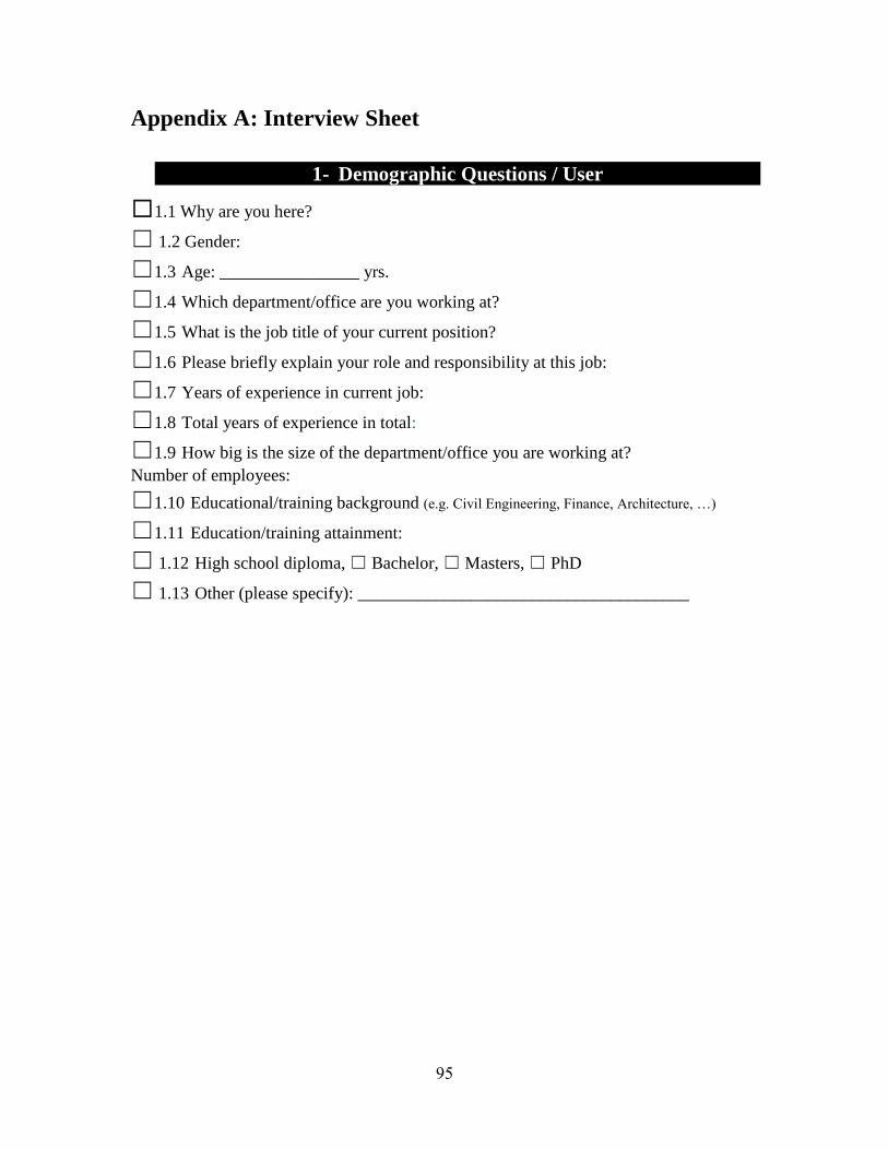
95
Appendix A: Interview Sheet
1- Demographic Questions / User
☐1.1 Why are you here?
☐ 1.2 Gender:
☐1.3 Age: ________________ yrs.
☐1.4 Which department/office are you working at?
☐1.5 What is the job title of your current position?
☐1.6 Please briefly explain your role and responsibility at this job:
☐1.7 Years of experience in current job:
☐1.8 Total years of experience in total:
☐1.9 How big is the size of the department/office you are working at?
Number of employees:
☐1.10 Educational/training background (e.g. Civil Engineering, Finance, Architecture, …)
☐1.11 Education/training attainment:
☐ 1.12 High school diploma, ☐ Bachelor, ☐ Masters, ☐ PhD
☐ 1.13 Other (please specify): ______________________________________

96
2- Operational Requirements
2.1 Division Statistics
☐2.1.1 Workforce breakdown: total number, white-vs.-blue collar, indoor-vs-
outdoor, data gatherer vs. data processors
☐2.1.2 Project load breakdown: total number of projects per year, average number of
parallel projects
☐2.1.3 Project type breakdown: in-house data usage vs. external/shared data usage
☐2.1.4 IT: data storage, data sharing, agreements, data classification and access (public
vs. non-public)
2.2 Specific Division Tasks
☐2.2.1 What are the different tasks/operations performed in your department?
☐2.2.2 Who are the key decision-makers/performers of those tasks?
☐2.2.3 What are the goals and sub goals when performing each task?
☐2.2.4 What are the decisions should be made for achieving each decision?
☐2.2.5 What are the information requirement for making those decisions and
performing each sub-goal?

97
3- Technology Analysis
3.1 Data Collection
☐3.1.1 Tools used on the job site and in the office
☐3.1.2 Training and or qualifications necessary to use those tools with a focus on using
the tools to collect usable data.
☐3.1.3 Generic vs. specialized tools
☐3.1.4 Tools used as a means to an end, i.e. tool necessary to enable work on site but
not involved in the direct data collection process, i.e. tools used as an enabler and not as a
sensor
3.2 Data Access
☐3.2.1 Interaction type
☐3.2.2 Paper vs. electronic format
☐3.2.3 Mobile/handheld
☐3.2.4 2D/3D CAD/visualization tools/software
☐3.2.5 Internet Access
☐3.2.6 Software
☐3.2.7 Common Sensors (Video/picture (Real-time), GPS, Surveying Tools) Other?:
3.3 Collected data
☐3.3.1 What is the raw collected data and how does that relate to the actually needed
data.
☐Directly collectable data vs. inferred data
☐Data requirements: accuracy, timeliness, repeatability
☐Importance: necessary primary data vs. easily collectable data providing
context
☐Cost vs. value of data collection

98
3.4 Data post-processing
☐3.3.2 Is the data collected indeed the data needed?
☐Immediate post-processing actions necessary to extract the required data (in
cases where a direct collection isn't possible)
☐Cost vs. value: post-processing, data storage
☐Classification: useful vs. useless, public vs. non-public
☐Training requirements to do the post-processing.

99
4- Working Environment
☐4.1 Location of site: near, far, indoors, outdoors
☐4.2 Time of year: all seasons vs. a prevailing season
☐4.3 Site safety: hard hat area, ongoing construction, site specific hazards
☐4.4 Site specific training requirement
________________________________________
☐4.5 Equipment necessary to access the site (enabling tools)
________________________
☐4.6 Sitting vs. Standing vs. While mobile
______________________________________
☐4.7 Indoors vs. Outdoors
____________________________________________________
☐4.8 Issues affecting your tasks in either indoor or outdoor environments?
☐Heat ☐Cold ☐Wind ☐Rain ☐Snow ☐Humidity ☐Perspiration
__________________________________________________________________
☐4.9 Preferred/fluent/first language (Choose one):
☐ English, ☐ Spanish, ☐ French, ☐
Other:_______________________________
☐4.10 Which type of special clothing might you wear while working?
☐ Hardhat, ☐ Earplugs/hearing protection, ☐ Gloves, ☐ Goggles, ☐ Mask,
☐ Backpack☐ Other (please specify): _________________________________

100
5- UAVs in Your Department /Office
5.1 Questions about each identified tasks
☐5.1.1 “Revisiting X, do you think this is the best way doing it? What would you
change of you hadn't budget or time constraints?”
☐5.1.2 “If you had a magic lamp with a genie at your disposal, what specific wishes
would you have on the job site?”
5.2 Sensor tool questions
☐5.2.1 Aerial photography
____________________________________________________
☐5.2.2 Limited in framing your photo
___________________________________________
☐5.2.3 Change your perspective
________________________________________________
☐5.2.4 A third person spectator
_________________________________________________
☐5.2.5 Geo-referenced pictures
_________________________________________________
☐5.2.6 A real time or time-lapse video
___________________________________________
☐5.2.7 Image in a different spectrum (e.g. Near or far infrared)
________________________
☐5.2.8 Positioning of your scanner
_______________________________________________
☐5.2.9 Overlying photographic pictures over your collected 3D data
____________________
☐5.2.10 A point in the sky that you could reference stuff to
☐5.2.11 A GPS with latitude, longitude, and altitude readout instead of you geodetic
equipment _____________________________________________________________
☐5.2.12 Visualize locations in 3D-space, i.e. the elevation of the third floor or the

101
clearance of a planned bridge
________________________________________________________
☐5.2.13 Wind speeds and directions on you site
____________________________________
☐5.2.14 Somebody on lookout and count X for you over the course of a day or two
_____________________________________________________________________
☐5.2.14 A motion track of equipment X over the course of a day
________________________
☐5.2.15 A 3D overlay of X right now on your iPad
___________________________________

102
Appendix B: IRB and Consent Forms

103
Consent to be a Research Participant
GA Tech Schools of Building Construction and Aerospace Engineering
Project: Feasibility Study to Determine the Economic and Operational Benefits of
Utilizing Unmanned Aerial Vehicles (UAVs)
Principal Investigator: Dr. Javier Irizarry (678-480-6035)
Co-Principal Investigators: Dr. Eric N. Johnson (404-385-2519)
Students: Masoud Gheisari (404-385-6779), Claus Christmann (404-894-0657), and
Ebrahim P. Karan (404-385-6779)
Duration of Study: One hour
Total Compensation: None
Number of Participants: 70 volunteers (Directors and administrators at GDOT
divisions/offices)
Participation limitations: Normal or corrected to normal vision.
General: You are being asked to be a volunteer interviewee in a research study. To
participate, you must read and agree to the following before you may proceed with the
survey.
Study Description: All divisions and offices of the Georgia Department of
Transportation (GDOT) would be studied to identify the ones that have the potential for
using UAVs. This analysis is performed by investigating the operations, mission and sets
of responsibilities that each division and their internal offices might have. Interviewing
directors or administrators of each division or office would help to build a clearer picture
of what would be general goals and tasks of different divisions and offices.
Procedures: A semi-structured interview will take place in which you will be asked
about (1) your goals and sub-goals, (2) decisions you make for achieving those goals, and
(3) information you might need for achieving each of those goals. You, as a professional
GDOT employee, are being asked to take part in the interview and answer the questions
you are asked by the interviewer.

104
Benefits: There is no direct benefit to you, however; your participation will help advance
scientific knowledge in the GDOT practices.
Compensation and cost: You will not be compensated for participating in this study and
there are no costs to you by participating in this study.
Foreseeable Risks or Discomforts: There are no foreseeable risks to you by
participating.
Confidentiality: The following procedures will be followed to keep your personal
information confidential in this study: Data that is collected from you will be kept private
to the extent allowed by law. Neither your name nor any other fact that might point to
you will not be collected for this research. To further protect your privacy, your records
will be kept under a coded number unrelated to you. Your records will be kept in locked
files and only the project investigators and the student researcher you worked with will be
allowed to look at them. Since your name or other identifiers will not be collected, there
is no possibility that your name will appear when results of this study are presented or
published. To make sure that this research is being carried out in the proper way, the
Georgia Institute of Technology Institutional Review Board will review the study records.
Furthermore, the Office of Human Research Protections may also look over study records
during required reviews.
Contact: If you have any questions about this study or its procedures, please contact Dr.
Javier Irizarry at telephone # (678) 480-6035.
Statement of Rights: Your participation in this study is voluntary. You do not have to be
in this study if you don't want to be. You have the right to change your mind and leave
the study at any time without giving any reason, and without penalty. If you have any
questions about your rights as a research volunteer, call or write to: The Institutional
Review Board, Office of Research Compliance, 505 Tenth Street, Atlanta, GA 30318.
Phone: 404-385-2175; Fax: 404-385-2081.
Consent: If you sign below, it means that you have read (or have had read to you) the
information given in this consent form, and you would like to be a volunteer in this study.

105
Appendix C: Interview Validation Form (Example)

106

107

108

109
Appendix D: Validated Tasks
Task ID#: 1 Division: Traffic Operations Subjects
Responded:
1, 9, 10, and 16
Task Goal: GDOT is required to coordinate traffic safety, traffic engineering, and traffic
management state wide. To facilitate this, ITS personnel are tasked to oversee the
collection of traffic data for related monitoring, prediction, and assessment activities.
Task Activities: The task includes the electronic collection of data, including, but not
limited to, traffic flow, traffic speed, and traffic counts. The data are either directly
obtained from GDOT maintained traffic devices or purchased from third party vendors
and their collection systems. The data are processed and translated from the native format
to a format suitable for the monitoring, prediction, and assessment activities utilizing the
data.
Environment
Summary:
All year around, Indoor, Sitting, and Local
Task Dimension
(average):
80 yds.
Task Distance
(average):
- hrs.
Task Duration
(average):
3.3 hrs.
Task Frequency
(most):
daily
Tools: "511 Calls", Fire and Police Depts., GDOT Databases, Ramp Meters, Ball
Bank Indicator, DMI, Radar Detection, Tube Counters, Microwave
Detection, Optical Flow Devices, Live Video Feeds, INRIX Data, And
Towing Service Providers.
Average Cost: $113

110
Task ID#: 2 Division: Traffic Operations Subjects
Responded:
1, 9, 10, and 16
Task Goal: Throughout the state various special events affect arterial roadways and other
main roads. GDOT personnel is tasked to supervise special event traffic detours and road
closures and to coordinate the work of the traffic operation division with other involved
agencies.
Task Activities: The task includes the processing of real-time traffic data in the context
of special events (e.g. sport events, festivals, demonstrations) or weather effects (e.g.
flooding, fallen trees) that adversely affect traffic in order to optimize traffic throughput.
This involves, but is not limited to, optimizing detour routes, managing non-event traffic
in the affected area, and coordinating with other agencies at the scene (e.g. fire and police
departments, event management companies).
Environment
Summary:
All year around, Indoor, Sitting, and Local
Task Dimension
(average):
0.8 mile
Task Distance
(average):
- hrs.
Task Duration
(average):
2 hrs.
Task Frequency
(most):
Daily &
Weekly
Tools: Real-Time Traffic Data, Event Schedules, Historic Traffic Data,
Communication equipment to on-site agencies
Average Cost: $288

111
Task ID#: 3 Division: Traffic Operations Subjects
Responded:
1, 9, 10, and 16
Task Goal: GDOT personnel perform post-incident site inspections to investigate the
incident circumstances and how the incident could have been affected through traffic
management devices present at the scene. The discovered facts could be pertinent to
claims filed by the involved parties, potentially including the assessment of fault and
damages. If the installed devices are deemed insufficient to prevent a similar incident in
the future, a follow up improvement investigation might be triggered.
Task Activities: The task includes a site inspection that involves a rough mapping of the
site’s layout and topography and an overview of the installed traffic management devices
and their location(s) on site. Potentially damaged GDOT equipment is catalogued.
Environment
Summary:
All year around, Outdoor, both Mobile and Sitting, and Local
Task Dimension
(average):
0.28 mile (or 490
yds.)
Task Distance
(average):
2 hrs.
Task Duration
(average):
1 hr.
Task Frequency
(most):
Weekly
Tools: Incident Reports, Maps and Plans, Historic Traffic Data, Communications
equipment to on-site agencies, "GEARS" (Traffic Data Software), GPS,
Camera, Measuring Wheels, DMI, Ball Bank Indicator, Level
Average Cost: $47

112
Task ID#: 6 Division: Traffic Operations Subjects
Responded:
1, 9, 10, and 16
Task Goal: GDOT District Personnel is tasked to oversee the installation and
maintenance of traffic signal devices on State Routes in order to keep the system(s)
functioning correctly. In this context, GDOT employees oversee and/or perform proactive
maintenance and repair activities on traffic signal systems in their district.
Task Activities: The task involves the inspection of a traffic signal installation either as a
response to a failure or malfunction report or in the context of a routine maintenance
schedule. At the site of the traffic signal installation, the task requires confirming either
the correct operation or the presence of a malfunction or physical damage. In the case of
incorrect operation of the device, the appropriate response is triggered. Potential (interim)
remedies could involve a system reset or shut down.
Environment
Summary:
All year around, Outdoor, Mobile, and Local
Task Dimension
(average):
100 yds.
Task Distance
(average):
1 hr.
Task Duration
(average):
1.3 hrs.
Task Frequency
(most):
Hourly & Daily
Tools: Personal high-visibility safety gear, Device Manual/Handbook, Malfunction
Report, Pen and Paper, Basic Hand Tools, GDOT Vehicle, Computer
Average Cost: $50

113
Task ID#: 43 Division: Traffic Operations Subjects
Responded:
1, 9, 10, and
16
Task Goal: GDOT District Personnel is required to maintain an understanding of the
overall traffic situation in their area in order to properly develop and update traffic plans.
In this regard, GDOT personnel collect representative speed samples.
Task Activities: The task includes the identification of appropriate site locations for
conducting speed sample measurements. Depending on the selected site, the sample is
taken either with a RADAR gun, from a floating sample, or deduced from INRIX data.
The collected data are processed and translated into the proper format for further traffic
evaluation and modeling tasks.
Environment
Summary:
All year around, Outdoor, Sitting, and Distributed
Task Dimension
(average):
2.9 mile
Task Distance
(average):
2 hrs.
Task Duration
(average):
2 hrs.
Task Frequency
(most):
Weekly & Monthly
Tools: Radar Gun, Speedometer, GDOT Vehicle, Pen and Paper, Plans and Maps,
Radar Gun, Speedometer, INRIX Data
Average Cost: $80
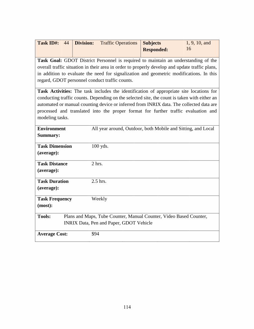
114
Task ID#: 44 Division: Traffic Operations Subjects
Responded:
1, 9, 10, and
16
Task Goal: GDOT District Personnel is required to maintain an understanding of the
overall traffic situation in their area in order to properly develop and update traffic plans,
in addition to evaluate the need for signalization and geometric modifications. In this
regard, GDOT personnel conduct traffic counts.
Task Activities: The task includes the identification of appropriate site locations for
conducting traffic counts. Depending on the selected site, the count is taken with either an
automated or manual counting device or inferred from INRIX data. The collected data are
processed and translated into the proper format for further traffic evaluation and
modeling tasks.
Environment
Summary:
All year around, Outdoor, both Mobile and Sitting, and Local
Task Dimension
(average):
100 yds.
Task Distance
(average):
2 hrs.
Task Duration
(average):
2.5 hrs.
Task Frequency
(most):
Weekly
Tools: Plans and Maps, Tube Counter, Manual Counter, Video Based Counter,
INRIX Data, Pen and Paper, GDOT Vehicle
Average Cost: $94

115
Task ID#: 45 Division: Traffic Operations Subjects
Responded:
1, 9, 10, and
16
Task Goal: GDOT District Personnel is required to maintain an understanding of the
overall traffic situation in their area in order to properly develop and update traffic plans.
In this regard, GDOT personnel conduct turning movement counts.
Task Activities: The task includes the identification of appropriate intersections for
conducting turning movement counts. Depending on the selected site, the count is taken
with either an automated or manual counting device or inferred from INRIX data. The
collected data are processed and translated into the proper format for further traffic
evaluation and modeling tasks.
Environment
Summary:
All year around, Outdoor, both Mobile and Sitting, and Local
Task Dimension
(average):
100 yds.
Task Distance
(average):
2 hrs.
Task Duration
(average):
3 hrs.
Task Frequency
(most):
Weekly
Tools: Plans and Maps, Tube Counter, Video Based Counter, GDOT Vehicle,
Turning Movement Counter
Average Cost: $96

116
Task ID#: 46 Division: Traffic Operations Subjects
Responded:
1, 9, 10, and
16
Task Goal: GDOT District Personnel is tasked to continuously improve the flow of
traffic and respond to activities potentially impacting it. In this regard, GDOT personnel
conduct on-site inspections to improve already installed systems or to study and assess
the impact of proposed alterations of, for example, traffic devices or the right-of-way.
Task Activities: The task includes the initial familiarization with the inspection site as
well as the collection of several traffic data types. Amongst the measurements taken
could be traffic counts, speed samples, traffic flow, and sight distances. Furthermore,
GDOT personnel could review safe speeds (depending on road conditions and ball bank
measurements), the installation of signage, and existing of planned striping. The collected
data are processed and translated to support a following evaluation and subsequent
assessment of either the current situation or the proposed alteration.
Environment
Summary:
All year around, Outdoor, both Mobile and Sitting, and
Distributed
Task Dimension
(average):
1.4 mile
Task Distance
(average):
2 hrs.
Task Duration
(average):
1.8 hrs.
Task Frequency
(most):
Weekly
Tools: Plans and Maps, Manual Traffic Counter, Radar Gun, Distance Meter,
Measuring Wheel, Range Finder, Pen and Paper, GDOT Vehicle
Average Cost: $60

117
Task ID#: 4 Division: Construction Subjects
Responded:
2, 6, 8, 11, 12, 13
and 14
Task Goal: GDOT construction engineers are responsible to oversee, inspect, and
monitor contractual field work. In this regard, they enforce standard specifications,
coordinate testing of installed materials and take field measurements of pay items. Also,
they deal with land owners, local and state stakeholders, both public and private.
Task Activities: The task includes performing several linear measurements, computing
areas and volumes from linear measurements, and taking counts of items billed as “each”.
The data are collected on site and respective notes are taken, primarily on paper. After the
collection of the raw measurements and counts, some post-processing is done to compute
areas or volumes. After that, the data are transferred into the software “Site Manager” for
further processing.
Environment
Summary:
All year around, Outdoor, Mobile, and mostly Local
Task Dimension
(average):
2.9 mile
Task Distance
(average):
1.8 hrs.
Task Duration
(average):
2.6 hrs.
Task Frequency
(most):
Hourly
Tools: Measuring Wheel, Tape Measure, Pen and Paper, "Site Manager", Plans and
Drawings, Computer, "Word", "Excel", "Outlook", Calculator, Distance
Meter, Mobile Internet in Vehicle, Traffic Marking Paint, Level and Grade
Rod
Average Cost: $66
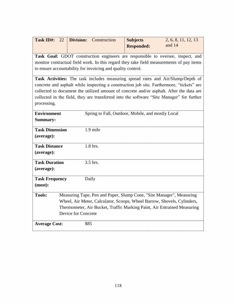
118
Task ID#: 22 Division: Construction Subjects
Responded:
2, 6, 8, 11, 12, 13
and 14
Task Goal: GDOT construction engineers are responsible to oversee, inspect, and
monitor contractual field work. In this regard they take field measurements of pay items
to ensure accountability for invoicing and quality control.
Task Activities: The task includes measuring spread rates and Air/Slump/Depth of
concrete and asphalt while inspecting a construction job site. Furthermore, “tickets” are
collected to document the utilized amount of concrete and/or asphalt. After the data are
collected in the field, they are transferred into the software “Site Manager” for further
processing.
Environment
Summary:
Spring to Fall, Outdoor, Mobile, and mostly Local
Task Dimension
(average):
1.9 mile
Task Distance
(average):
1.8 hrs.
Task Duration
(average):
3.5 hrs.
Task Frequency
(most):
Daily
Tools: Measuring Tape, Pen and Paper, Slump Cone, "Site Manager", Measuring
Wheel, Air Meter, Calculator, Scoops, Wheel Barrow, Shovels, Cylinders,
Thermometer, Air Bucket, Traffic Marking Paint, Air Entrained Measuring
Device for Concrete
Average Cost: $85
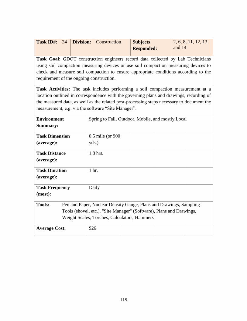
119
Task ID#: 24 Division: Construction Subjects
Responded:
2, 6, 8, 11, 12, 13
and 14
Task Goal: GDOT construction engineers record data collected by Lab Technicians
using soil compaction measuring devices or use soil compaction measuring devices to
check and measure soil compaction to ensure appropriate conditions according to the
requirement of the ongoing construction.
Task Activities: The task includes performing a soil compaction measurement at a
location outlined in correspondence with the governing plans and drawings, recording of
the measured data, as well as the related post-processing steps necessary to document the
measurement, e.g. via the software “Site Manager”.
Environment
Summary:
Spring to Fall, Outdoor, Mobile, and mostly Local
Task Dimension
(average):
0.5 mile (or 900
yds.)
Task Distance
(average):
1.8 hrs.
Task Duration
(average):
1 hr.
Task Frequency
(most):
Daily
Tools: Pen and Paper, Nuclear Density Gauge, Plans and Drawings, Sampling
Tools (shovel, etc.), "Site Manager" (Software), Plans and Drawings,
Weight Scales, Torches, Calculators, Hammers
Average Cost: $26

120
Task ID#: 25 Division: Construction Subjects
Responded:
2, 6, 8, 11, 12, 13
and 14
Task Goal: GDOT construction engineers are responsible to oversee, inspect, and
monitor contractual field work. In this regard, they take field measurements of pay items
such as concrete to ensure correct invoicing.
Task Activities: The task includes measuring the material poured for construction in
cubic yards (or cubic feet) to document the utilized amount of concrete and/or asphalt as
well as checking the amount of the related earthwork. This is done either directly via the
collection of “tickets” from the dispensing device or indirectly via the computation of
volumes, based on manual linear measurements. After the data are collected in the field,
they are transferred into the software “Site Manager” for further processing.
Environment
Summary:
Spring to Fall, Outdoor, Mobile, and mostly Local
Task Dimension
(average):
1.9 mile
Task Distance
(average):
1.8 hrs.
Task Duration
(average):
1.5 hrs.
Task Frequency
(most):
Hourly
Tools: Measurement Tape, Pen and Paper, "Tickets" (Concrete or Asphalt), "Site
Manager" (Software), Calculator, Plans and Drawings, Thermometer,
Measurement Wheel, Slum Cones, Air Meters, Scoops, Traffic Marking
Paint, Distance Meter. Air Entrained Device for Concrete
Average Cost: $46

121
Task ID#: 9 Division: Intermodal Subjects
Responded:
9
Task Goal: GDOT’s Intermodal Division is tasked to inspect general aviation airports in
GA biennially for compliance with state and federal law as well as to record relevant data
for dissemination amongst the general aviation community. If a noncompliance is
detected, appropriate remedy measures are to be triggered.
Task Activities: The task mainly involves the collection of obstacle related data. The
approach and departure corridors are checked to be clear of obstacles; if obstacles are
detected, their location is recorded and, if possible, their removal triggered. Furthermore,
data is collected with respect to the overall geometry of the runway(s), the state of the
runway(s), potential obstacles on or in the direct vicinity of the airport, and wildlife
activity which could interfere with general aviation procedures.
Environment
Summary:
Spring to Fall, Outdoor, Mobile, and Local
Task Dimension
(average):
3 mile
Task Distance
(average):
4 hrs.
Task Duration
(average):
3.5 hrs.
Task Frequency
(most):
Weekly
Tools: Measuring Wheel, Range Finder, Pen and Paper, Clinometer, Compass,
Camera
Average Cost: $227

122
Task ID#: 47 Division: Intermodal Subjects
Responded:
21
Task Goal: GDOT intermodal engineers are responsible to oversee, inspect, and monitor
contractual field work in the context or rail operations. In this regard, they take field
measurements of pay items.
Task Activities: The task mainly involves the collection of obstacle related data. The
approach and departure corridors are checked to be clear of obstacles; if obstacles are
detected, their location is recorded and, if possible, their removal triggered. Furthermore,
data is collected with respect to the overall geometry of the runway(s), the state of the
runway(s), potential obstacles on or in the direct vicinity of the airport, and wildlife
activity which could interfere with general aviation procedures.
Environment
Summary:
All year around, Outdoor, Mobile, and Distributed
Task Dimension
(average):
5 mile
Task Distance
(average):
2 hrs.
Task Duration
(average):
2.5 hrs.
Task Frequency
(most):
Weekly
Tools: Form 5010, Paper and Pencil, Range Finder, Compass, Measuring Wheel,
Camera, Aviation Radio, Yellow Signal Lights, Placement Flags,
Airport/Facility Directory, Inspection questionnaire and checklist,
Inclinometer
Average Cost: $165

123
Task ID#: 48 Division: Bridge
Inspection
Subjects
Responded:
23a
Task Goal: GDOT employees are tasked to conduct regularly scheduled routine
inspections of conventional bridges in Georgia. The goal of this task is to determine the
physical and functional condition of a bridge and to identify changes compared to
previous inspections. Furthermore, these routine inspections are to ensure that a bridge
continues to satisfy all applicable serviceability requirements.
Task Activities: These inspections associated are mainly visual inspections. The task is
performed either from the deck or ground level or from permanent-access structures,
potentially in the presence of regular traffic over and under the structure. Personal safety
gear is worn.
Environment
Summary:
All year around, Outdoor, Mobile, and Distributed
Task Dimension
(average):
1 mile
Task Distance
(average):
2 hrs.
Task Duration
(average):
45 min.
Task Frequency
(most):
Daily
Tools: Maps and Plans, Flashlight, Sounding Hammer, Measurement Tape, Plumb
Bob, Ladder, Safety Harness, Knife, chest waders, hip waders, Laser
distance meter, range rod, 25’ telescoping survey rod, 100’ fiberglass tape
weighted, wire brush, calipers, digital level, angle finder, binoculars, digital
camera, GPS, cordless drill, timber probe, machete, thermometer, pole
camera, bush axe, bore scope, and thermal imagining camera.
Average Cost: $50

124
Task ID#: 49 Division: Bridge
Inspection
Subjects
Responded:
23a
Task Goal: GDOT employees are tasked to conduct in-depth inspections of bridges in
Georgia. The goal of this task is to identify deficiencies not normally detectable during
regular routine inspections.
Task Activities: The inspections associated with an in-depth inspection normally involve
the use of non-destructive examination techniques beyond a visual inspection. The task is
performed either from the deck or ground level or from permanent-access structures,
potentially in the presence of regular traffic over and under the structure. Personal safety
gear is worn.
Environment
Summary:
All year around, Outdoor, Mobile, and Distributed
Task Dimension
(average):
1 mile
Task Distance
(average):
2 hrs.
Task Duration
(average):
2.5 hrs.
Task Frequency
(most):
Weekly
Tools: Maps and Plans, Flashlight, Sounding Hammer, Measurement Tape, Plumb
Bob, Ladder, Safety Harness, Dye Penetrant Testing Device, Knife, chest
waders, hip waders, safety glasses, gloves, Laser distance meter, range rod,
25’ telescoping survey rod, 100’ fiberglass tape weighted, wire brush,
calipers, digital level, angle finder, binoculars, digital camera, GPS, cordless
drill, timber probe, machete, thermometer, boat (paddles and PFD’s), pole
camera, bush axe, bore scope, and thermal imagining camera.
Average Cost: $103

125
Task ID#: 50 Division: Bridge
Inspection
Subjects
Responded:
23a
Task Goal: GDOT employees are tasked to conduct special or damage inspections of
conventional bridges in Georgia. The goal of this task is to identify the physical and
functional condition of a structure, including deficiencies not normally detectable during
regular routine inspections, especially after potentially negative environmental of man-
made events in order to assess structural damage and the need for further follow-up
actions. (1: As opposed to complex bridges, e.g. major river bridges, movable,
suspension, cable stayed, or other bridges with unusual characteristics.)
Task Activities: The scope of each special inspection is unique and depends on the
structure and the event triggering the special inspection, but could involve the use of
special access equipment.
Environment
Summary:
All year around, Outdoor, Mobile, and Distributed
Task Dimension
(average):
1 mile
Task Distance
(average):
2 hrs.
Task Duration
(average):
2.5 hrs.
Task Frequency
(most):
Weekly
Tools: Maps and Plans, Flashlight, Sounding Hammer, Measurement Wheel,
Plumb Bob, Ladder, Safety Harness, Rebar Locator, Dye Penetrant Testing
Device, Access Enabling Equipment (Under Bridge Inspection Snoopers,
Sectional Barge, Man Lifts, Bridge Rigging), Knife, chest waders, hip
waders, Laser distance meter, range rod, 25’ telescoping survey rod, 100’
fiberglass tape weighted, wire brush, calipers, digital level, angle finder,
binoculars, digital camera, GPS, cordless drill, timber probe, machete,
thermometer, boat (paddles and PFD’s), pole camera, bush axe, bore scope,
and thermal imagining camera.
Average Cost: $1140

126
Task ID#: 51 Division: Bridge
Inspection
Subjects
Responded:
23a
Task Goal: GDOT employees are tasked to conduct special or damage inspections of
complex bridges in Georgia. The goal of this task is to identify the physical and
functional condition of a structure, including deficiencies not normally detectable during
regular routine inspections, especially after potentially negative environmental of man-
made events in order to assess structural damage and the need for further follow-up
actions (e.g. major river bridges, movable, suspension, cable stayed, or other bridges with
unusual characteristics.)
Task Activities: The scope of each special inspection is unique and depends on the
structure and the event triggering the special inspection, but could involve the use of
special access equipment.
Environment
Summary:
All year around, Outdoor, Mobile, and Distributed
Task Dimension
(average):
1 mile
Task Distance
(average):
2 hrs.
Task Duration
(average):
3.5 hrs.
Task Frequency
(most):
Weekly
Tools: Maps and Plans, Flashlight, Sounding Hammer, Measurement Tape,
Measurement Wheel, Plumb Bob, Ladder, Safety Harness, GDOT Vehicle,
Rebar Locator, Access Enabling Equipment (Under Bridge Inspection
Snoopers, Sectional Barge, Man Lifts, Bridge Rigging), Knife, chest
waders, hip waders, safety glasses, gloves, Laser distance meter, range rod,
25’ telescoping survey rod, 100’ fiberglass tape weighted, wire brush,
calipers, digital level, angle finder, binoculars, digital camera, GPS, cordless
drill, timber probe, machete, thermometer, boat (paddles and PFD’s), pole
camera, bush axe, bore scope, and thermal imagining camera.
Average Cost: $1164

127
Task ID#: 52 Division: Bridge
Inspection
Subjects
Responded:
23a
Task Goal: GDOT employees are tasked to conduct inspections of underwater elements
and structures of bridges in Georgia. The goal of this task is to routinely identify the
physical and functional condition of the elements, identify changes compared to previous
inspections, and to detect deficiencies not normally detectable during routine or in-depth
above water inspections.
Task Activities: The task includes getting divers to the underwater elements, potentially
briefing the divers with special requests, conducting the inspection, and evaluating the
data returned from by the divers. The task is performed mainly being swimming/diving;
with non-related water traffic is presumably being suspended. Personal safety gear is
worn.
Environment
Summary:
All year around, Outdoor, Mobile, and Local
Task Dimension
(average):
100 yds.
Task Distance
(average):
2 hrs.
Task Duration
(average):
4.5 hrs.
Task Frequency
(most):
Monthly
Tools: Maps and Plans, Flashlight, Camera, Measurement Tape, Diving
Equipment, Life Jackets, Safety Harness, GDOT Vehicle, Barge or Boat,
Pen and Paper, While not used on every inspection, in addition to the items
checked above, we also use: Imaging Sonar, Underwater video camera,
knife, machete, range rod, bush axe, 25’ telescoping survey rod, calipers,
thermometer, sounding hammer, oyster scrapers, depth finder, and 100’
weighted tape.
Average Cost: $405

128
Appendix E: Exemplary Process Descriptions for UAS-aided
Tasks
The iterative process used to categorize the identified GDOT tasks (see Chapter IV)
included creating process descriptions of the identified tasks which would utilize one of
the proposed reference systems. As these assumed process descriptions provide
theoreticized examples of using one of the proposed UAS, they are reproduced here to
describe possible GDOT usage scenarios.
Three identified tasks are unlikely to be aided through UAS and hence have no related
process description: asphalt and concrete inspections, soil compaction measurements, and
underwater bridge inspections. The first two tasks involve equipment that is likely to be
unmovable by UAV sized for the task environment and the third application would
require an unmanned underwater vehicle (UUV).
Construction Site Measurements
GDOT Division: Construction Proposed UAS: Flying Camera (A)
physically relocate to centroid of current activity area
deploy system
for small linear measurement: position system so that extends are in view, select linear
measurement mode, click start and end in Utility Cam screen, read length estimate
for large linear measurement: position system at start of stretch to be measured,
engage measurement mode, fly to next corner, click on Utility Cam screen, read length
estimate
for small area measurement: position system so that extends are in view, select area
measurement mode, click corners in Utility Cam screen, read area estimate
for large area measurement: position system so that the first corner is in view, select
on Utility Cam, fly to next corner(s), select, read area estimate
for volume measurement: position system so that extends are in view, select volume
measurement mode, click corners of boundary in Utility Cam screen, start automatic
measurement flight, read volume estimate
for counting operations: fly system to items to be counted, aim FPV or Utility Cam
screen at item, click to count and mark, read running total
upload to Site Manager
Traffic Signal Installation Inspection
GDOT Division: Traffic Operations Proposed UAS: Perching Camera (C)
determine closest UAV to traffic signal site and deploy it
fly to traffic signal site (FPV or waypoints)
use Utility Cam to determine if signal is functional correctly/incorrectly
if signal is malfunctioning and rigged accordingly, trigger traffic signal reset

129
Note: System C is not equipped for "manipulating" elements other than through
"bumping into" them.
Traffic Signal Installation Inspection
GDOT Division: Traffic Operations Proposed UAS: MALE (D)
determine closest airborne UAV to traffic signal site and activate it
fly to traffic signal site (waypoints)
orient sensor package to lock on to the signal installation and loiter
use E/O video sensor to determine if signal is functional correctly/incorrectly
use "click to locate" to get georeferenced coordinates to identify locations for
potentially necessary follow ups.
Note: System D would be flying high above the installation. See Post-Incident Inspection
for a related application.
On-Site Traffic Inspection
GDOT Division: Traffic Operations Proposed UAS: Flying Camera (A)
physically relocate to the traffic inspection site
deploy system
use FPV to do an initial "visual inspection": explore the site and detect and localize
traffic related items such as signs, signals, and striping through interaction with the
relayed video feed.
use the system to measure site dimensions (see Construction Site Measurements for
details.)
Note: System A would most likely not have the capability to perform vision based traffic
data collection.
On-Site Traffic Inspection
GDOT Division: Traffic Operations Proposed UAS: Perching Camera (C)
determine closest UAV to traffic signal site and deploy it
fly to traffic inspection site (FPV or waypoints)
use FPV to do an initial "visual inspection": explore the site and detect and localize
traffic related items such as signs, signals, and striping through interaction with the
relayed video feed.
use the system to measure site dimensions (see Construction Site Measurements for
details.)
determine a suitable perching position, land the system and conduct vision based
traffic data collection (see Traffic Data Collection, Traffic Count Measurement,
Traffic Movement Measurement for details.)
engage Return-to-Base after data were collected

130
Airport Inspection
GDOT Division: Intermodal Proposed UAS: Flying Total Station (B)
preload airport plans and map into the system
physically relocate to the airport
deploy the system
use high precision navigation to fly to the runway ends
use calibrated video to determine approach/departure corridor clearance
use "click to localize" feature to mark intruding obstructions
Note: The physical extends of an airport most likely render tethered operations infeasible
(also, cut tethers could lead to FOD). In the future, LiDAR based SLAM could be used
the check taxi- and runway clearances to buildings (see Rail Site Inspection)
Bulk Material Measurement
GDOT Division: Construction Proposed UAS: Flying Camera (A)
physically relocate to centroid of current activity area
deploy system
use area measuring techniques (see Construction Site Measurement) to compute the
area material is poured over
manually measure (average) thickness of layer
compute volume from thickness and area
report to Site Manager
Bulk Material Measurement
GDOT Division: Construction Proposed UAS: Perching Camera (C)
physically relocate to site
deploy system at the pouring machine
track volume by "scanning" tickets with the Utility Cam
report to Site Manager
Bulk Material Measurement
GDOT Division: Construction Proposed UAS: Flying Total Station (B)
physically relocate to site
deploy system
generate a precise terrain map before the bulk material activity
(idle/wait till the activity is finished)
generate a precise terrain map after the bulk material activity
compute volume as the delta between the two
Note: this application could potentially be conducted while tethered.

131
Rail Site Inspection
GDOT Division: Intermodal Proposed UAS: Flying Total Station (B)
preload rail section plans and map into the system
physically relocate to the rail section
deploy the system
use high precision navigation to fly over the rail track
use calibrated video and/or (downward looking) 2D LiDAR to measure rail track
alignment
use calibrated video and/or (forward looking) 3D LiDAR to measure clearance above
and around the track
auto-detect misalignments and obstructions, georefenrence the locations
use "click to localize" feature to manually mark points of interest
Note: The physical extends of a rail track render tethered operations most likely
infeasible. However, potentially the system could be used in combination with a road-rail
vehicle trailing behind.
Traffic Data Collection
GDOT Division: Traffic Operations Proposed UAS: Perching Camera (C)
Note: This is a combination of Speed Sample Measurement, Traffic Count Measurement,
and Turning Movement Measurement.
Speed Sample Measurement
GDOT Division: Traffic Operations Proposed UAS: Perching Camera (C)
Optical Flow Process:
relocate to the measurement site
deploy system
determine a suitable location for perching
aim Utility Cam to sampling sector
identify lanes and direction of travel via the GUI
specify sampling time and start autonomous (vision based) speed measurements
Floating Sample Process:
relocate to the measurement site
deploy system
determine suitable perching location
determine the road to sample, direction of travel, and start and end points of the
measurements
aim Utility Cam at starting zone

132
upon detection of a (single) vehicle entering the starting zone, the system
autonomously follows the vehicle at a safe altitude until the end point and averages the
measured speed
the system returns to its perching location and waits for the next vehicle
Extended (Relay) Tracking Process:
determine the tracking corridor (route, start and end points)
determine participating (already perching) systems
upon entry of a (easily distinguishable) vehicle into the corridor, the first participating
system starts to track the vehicle and "hands it off" to the next system at the next
perching location
recorded data is joined and evaluated
Speed Sample Measurement
GDOT Division: Traffic Operations Proposed UAS: MALE (D)
Extended Tracking Process:
determine operational boundary, loiter area, stay-out zones, un-/safe altitudes,
emergency procedures (lost link, collision avoidance, etc.)
determine the tracking corridor (route, start and end points)
deploy a system
upon entry of a (easily distinguishable) vehicle/blob into the corridor the blob is
visually tracked
Traffic Count Measurement
GDOT Division: Traffic Operations Proposed UAS: Perching Camera (C)
determine closest system to measurement site and deploy it
fly to traffic inspection site (FPV or waypoints)
determine suitable perching location
point Utility Cam at measuring site
determine and identify measurement zones
conduct count
autonomous Return-to-Base
Turning Movement Measurement
GDOT Division: Traffic Operations Proposed UAS: Perching Camera
determine closest system to intersection and deploy it
fly to traffic inspection site (FPV or waypoints)

133
determine suitable perching location
point Utility Cam at measuring site
determine and identify lines and measurement zones (entry zone and potential exit
zones)
conduct count
autonomous Return-to-Base
Special Event Supervision
GDOT Division: Traffic Operations Proposed UAS: MALE (D)
determine operational boundary, loiter area, stay-out zones, un-/safe altitudes,
emergency procedures (lost link, collision avoidance, etc.)
determine the area of interest (boundaries, start and end points of entry/exit routes to
supervise)
deploy a system
upon reaching the area of interest the system starts to compute flow data for the
determined routes
operators can utilize the sensor suite for real time observation
Post-Incident Inspection
GDOT Division: Traffic Operations Proposed UAS: MALE (D)
determine closest airborne UAV to incident site and activate it
fly to incident site (waypoints)
orient sensor package to lock on the incident location and loiter
use E/O video sensor to determine site status
use "click to locate" to get georeferenced coordinates to identify locations for
potentially necessary follow ups.
Note: System D would be flying high above the installation. See Traffic Signal
Installation Inspection for a related application.
Conventional Bridge Inspection
GDOT Division: Bridge Inspection Proposed UAS: Complex Manipulation (E)
physically relocate to the bridge
deploy system
use FPV to maneuver system to inspection points
Detailed Bridge Inspection
GDOT Division: Bridge Inspection Proposed UAS: Complex Manipulation (E)
physically relocate to the bridge
deploy system

134
use FPV to maneuver system to inspection points
scan structure for latching hard-points
use Manipulator to latch and prepare inspection point
use Sensor Suite to inspect and record findings
Special Bridge Inspection
GDOT Division: Bridge Inspection Proposed UAS: Complex Manipulation (E)
physically relocate to the bridge
deploy system
use FPV to maneuver system to inspection points
scan structure for latching hard-points
use Manipulator to latch and prepare inspection point
use Sensor Suite to inspect and record findings
Special Bridge Inspection (Complex)
GDOT Division: Bridge Inspection Proposed UAS: Complex Manipulation (E)
physically relocate to the bridge
deploy system
use FPV to maneuver system to inspection points
scan structure for latching hard-points
use Manipulator to latch and prepare inspection point
use Sensor Suite to inspect and record findings

135
UAS Specifications
Airframe Payload Control Station System Capabilities
Rugged, Available Actuated Video
Camera
Portable, Interactive,
Rugged
Waypoint Navigation,
Vision Based Data
Extraction
Usage Scenarios
Construction Division (construction site measurement): The operator would simply start the
system, hover the UAV over the construction site while capturing video. The captured video is
transmitted back to the control station. Finally, the captured video and/or image is utilized and
processed to extract the quantities (e.g. linear, volume) of construction items.
Engineering Division (conventional bridge inspection): The operator would simply start the
system, hover the UAV over/under the selected scene while capturing video. The real time
video is transmitted back to the control station. Finally, the captured video and/or image is
utilized to provide visual overview of the bridge.
Intermodal Division (airport inspection): The operator would simply start the system, hover
the UAV over the airport while capturing video. The captured video is transmitted back to the
control station. Finally, the captured video and/or image is utilized to extract the geometry of
the airport.
Permits and Operations Division (supervise special events): The operator would simply start
the system, hover the UAV over the special event’s traffic while capturing video. The real time
video is transmitted back to the control station. Finally, the captured video and/or image is
utilized and processed to extract traffic data (e.g. flow, speed, counts) of roads or junctions.
Georgia DOT Research Project: Feasibility Study to Determine
the Economic and Operational Benefits of Utilizing UAVs
UAV System A Flying Camera

136
UAS Specifications
Airframe Payload Control Station System Capabilities
Probably
available
Actuated Sensor
Suite Portable, Interactive
Sense and Avoid, Waypoint Navigation,
Tethering, High-precision Navigation,
SLAM, Data Abstraction, Vision Based
Data Extraction
Usage Scenarios
Construction Division (bulk material measurement): The operator would simply start the
system, hover the UAV over the construction site while sending laser beams. The returned laser
pulse is transmitted back to the control station. Finally, the digital terrain map is utilized and
processed to extract the quantities (e.g. linear, volume) of bulk construction items.
Engineering Division (aerial surveying): The operator would simply start the system, hover the
UAV over the selected scene while sending laser beams. The returned laser pulse is transmitted
back to the control station. Finally, the digital terrain map is utilized for surveying, highway
design, corridor development, critical infrastructure protection, and highway safety.
Intermodal Division (airport inspection): The operator would simply start the system, hover
the UAV over the airport while sending laser beams. The returned laser pulse is transmitted
back to the control station. Finally, the digital surface map is utilized to extract the geometry of
the airport and location of obstructions.
Permits and Operations Division (post-incident site inspections): The operator would simply
start the system, hover the UAV over the incident site while sending laser beams. The returned
laser pulse is transmitted back to the control station. Finally, the digital surface map is utilized
and processed to mapping of the site’s layout and topography and the location of the installed
traffic management devices.
Georgia DOT Research Project: Feasibility Study to
Determine the Economic and Operational Benefits of
Utilizing UAVs
UAV System B Flying Total Station

137
UAS Specifications
Airframe Payload Control Station System Capabilities
Rugged,
probably
available
Actuated Video
and Sensor Suite,
Telepresence
System
Interactive,
Rugged, Portable
Sense and Avoid, Kinematic Constraint,
Unattended deployment and return, SLAM,
Advanced Networking, Vision Based Data
Extraction
Usage Scenarios
Construction Division (bulk material measurement): The operator determines the closest
UAV to the site, deploys and hovers the UAV over the construction site capturing video. The
UAV tracks the volume by scanning the material tickets with the Utility Cam. Finally, the
captured video and data is utilized and processed to extract the quantities (e.g. linear, volume)
of bulk construction items.
Engineering Division (conventional bridge inspection): The operator determines the closest
UAV to the site. Then he/she simply start the system, hover the UAV over/under the selected
scene while capturing video. The real time video is transmitted back to the control station.
Finally, the captured video and/or image is utilized to provide visual overview of the bridge.
Intermodal Division (airport inspection): The operator determines the closest UAV to the site.
Then he/she would start the system, hover the UAV over the airport while capturing video. The
captured video is transmitted back to the control station. Finally, the captured video and/or
image is utilized to extract the geometry of the airport.
Permits and Operations Division (traffic signal installation inspection): The operator
determines the closest UAV to the site and deploys it. UAV uses the Utility Cam to determine if
signal is functional correctly or not. If signal is malfunctioning and rigged accordingly, trigger
traffic signal reset.
Georgia DOT Research Project: Feasibility Study to
Determine the Economic and Operational Benefits of
Utilizing UAVs
UAV System C Perching Camera

138
UAS Specifications
Airframe Payload Control Station System Capabilities
Available,
Endurance
Actuated Video
and Sensor
Suite
Interactive
Sense and Avoid, Waypoint Navigation,
Unattended deployment and return,
Advanced Networking, Data Abstraction,
Vision Based Data Extraction
Usage Scenarios
Permits and Operations Division (speed sample measurement): The operator would determine
operational boundary, loiter area, stay-out zones, un-/safe altitudes, and the tracking corridor
(route, start and end points). Then starts the system, hover the UAV over the location. Upon entry
of a (easily distinguishable) vehicle into the corridor, the vehicle is visually tracked. The real time
video is transmitted back to the control station. Finally, the captured video and/or image is
utilized and processed to extract traffic data (e.g. flow, speed, counts) of roads or junctions.
Georgia DOT Research Project: Feasibility Study to
Determine the Economic and Operational Benefits of
Utilizing UAVs
UAV System D MALE

139
UAS Specifications
Airframe Payload Control Station System Capabilities
Rugged
Actuated Video
and Sensor Suite,
Manipulator
Interactive, Mobile
Sense and Avoid, Waypoint Navigation,
Kinematic Constraints, High-precision
Navigation, SLAM, Data Abstraction,
Vision Based Data Extraction
Usage Scenarios
Engineering Division (bridge inspection): The operator would physically relocate the UAV to
the bridge and deploy the system. Then, he/she uses FPV to maneuver system to inspection
points and uses Sensor Suite to inspect and record findings. For special bridge inspection, the
process continues with scanning the structure for latching hard-points. The operator would use
Manipulator to latch and prepare inspection point and use Sensor Suite to inspect and record
findings.
Georgia DOT Research Project: Feasibility Study to
Determine the Economic and Operational Benefits of
Utilizing UAVs
UAV System E Complex Manipulation
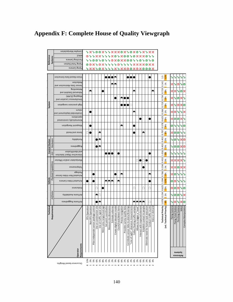
140
Appendix F: Complete House of Quality Viewgraph
Flying Camera
Flying Total Station
Perching Camera
MALE
Complex Manipulation
81
3%
FPV
Op
erat
ion
12
%N
on
-FP
V O
per
atio
n
35
%P
ilot-
ind
epen
det
se
nso
r p
acka
ge c
on
tro
l
46
%U
se o
n c
on
stru
ctio
n s
ite
35
%U
se a
t tr
affi
c si
gnal
sit
e
58
%M
etro
-are
a ra
nge
/co
vera
ge
12
%G
et p
oin
t co
ord
inat
es
35
%M
easu
re s
ite
dim
en
sio
ns
12
%Es
tim
ate
vo
lum
es
23
%C
reat
e d
igit
al e
leva
tio
n m
od
el
46
%C
ou
nt/
trac
k/d
etec
t it
em
s
46
%P
reci
se n
avig
atio
n
12
%P
rovi
des
su
rvey
-qu
alit
y d
ata
46
%C
orr
elea
te s
en
sor
dat
a to
pla
ns/
dra
win
gs
12
%"L
ine-
of-
sigh
t" c
lear
ance
mea
sure
men
ts
46
%C
olle
ct f
loat
ing
traf
fic
sam
ple
s
12
%A
llow
s to
tri
gger
a "
rese
t"
46
%In
tera
ct w
ith
insp
ecte
d e
lem
ent
35
%Es
tab
lish
co
nta
ct t
o p
eop
le
12
%El
imin
ate
nee
d f
or
hu
man
tas
k ex
ecu
tio
n
46
%C
on
du
ct t
raff
ic c
ou
nts
23
%D
ata
on
dem
and
Tech
nic
al P
rio
rity
(re
l. T
ech
nic
al P
rio
rity
)
Flyi
ng
Cam
era
Flyi
ng
Tota
l Sta
tio
n
Per
chin
g C
amer
a
MA
LE
Co
mp
lex
Man
ipu
lati
on
Reference
Systems
12
%5
%2
%6
%6
%6
%1
%3
%8
%3
%
0.7
34
0.7
19
0.1
41
1.5
0.4
53
0.4
53
0.7
97
0.5
78
0.6
25
0.2
66
8%
2%
5%
12
%6
%2
%
0.7
19
1.0
78
0.2
34
0.6
25
1.5
94
0.7
66
0.2
34
0.4
53
1.0
16
3%
6%
4%
Sensor Data Abstraction and
Reduction
Vision Based Data Extraction
Waypoint Navigation
Kinematically constrained
operations
Unattended deployment and
return
High-precision navigation
Simultaneous Location and
Mapping (SLAM)
Advanced Datalink and
Networking
Telepresence
Manipulator and/or Effector
Interactive Object Selection
and Identification
Ruggedness
Portability
Sense and Avoid
Syst
em
Re
fere
nce
Syst
em
sA
irfr
am
eP
ayl
oa
d C
ap
ab
iliti
esG
UI
Ha
rdw
are
Occurance-based Weights
Tech
nic
al
Re
qu
ire
me
nts
Ve
hic
leC
on
tro
l Sta
tio
n
Op
era
tor
Re
qu
ire
me
nts
Airframe Ruggedness
Airframe Availability
Endurance
Actuated Video Camera
Actuated Non-Video Sensor
Package
Dir
ecti
on
of
Imp
rove
men
t
We
akM
ediu
m3
"Les
s/Fe
we
r" is
bet
ter
1
No
min
al v
alu
e
"Mo
re/H
igh
er"
is b
ette
r
Imp
rove
me
nts
Stro
ng
5
We
igh
t
No
Pro
bab
ly N
o
Pro
bab
ly Y
es
Stro
ng
Neg
ativ
e
Neg
ativ
e
Po
siti
ve
Stro
ng
Po
siti
ve
Eval
uat
ion
Yes
Co
rre
lati
on
s

141
Appendix G: Reference System Technical Requirement Correlations
Vehicle Intra-relations
Airframe Ruggedness | Actuated Video Camera: negative
Actuated parts imply more moving parts which implies more potential for failure.
Airframe Ruggedness | Actuated Non-Video Sensor Package: negative
Actuated parts imply more moving parts which implies more potential for failure.
Airframe Ruggedness | Manipulator and/or Effector: strong negative
Manipulators and effectors most likely are mechanically dexterous, which implies joints and
motors or servos which could break.
Airframe Availability | Manipulator and/or Effector: strong negative
Manipulators and effectors could come from telerobotics or telemedicine applications. Such
devices would most likely have to be redesigned for reduced weight and as such are not
commercially available off-the-shelf products.
Endurance | Actuated Video Camera: negative
Everything that consumes power has a negative effect on endurance.
Endurance | Actuated Non-Video Sensor Package: negative
Everything that consumes power has a negative effect on endurance.
Endurance | Telepresence: negative
Everything that consumes power has a negative effect on endurance.
Endurance | Manipulator and/or Effector: strong negative
Manipulators and effectors most likely are mechanically dexterous, which implies joints and
motors, which in turn would require to be powered.
Actuated Video Camera | Actuated Non-Video Sensor Package: strong positive
If both systems can be collocated on a single pan-tilt turret, the overhead for adding the second
system should be rather small.
Actuated Video Camera | Telepresence: positive
While landed or perching, an actuated video camera could improve the situational awareness for
telepresence applications.
Telepresence | Manipulator and/or Effector: strong positive
The presence of an effector expands the telepresence beyond pure audio-visual applications.
Control Station Intra-relations
Interactive Object Selection and Identification | Ruggedness: negative
Ruggedized outdoor readable screens could be darker and lower in resolution, which could
diminish operator interaction through a touch based interface. Furthermore, rugged interface
could have to be operable with gloved hands, further decreasing precision of tactile operations.

142
Interactive Object Selection and Identification | Portability: negative
Larger improve identification and interaction, but smaller screens are preferable for portable
devices.
Ruggedness | Portability: negative
Rugged systems tend to be larger and bulkier than non-protected systems.
System Intra-relations
Sense and Avoid | Waypoint Navigation: positive
Sense and avoid allows to drop the free space assumption5 while navigating waypoints.
Sense and Avoid | Unattended Deployment and Return: strong positive
Sense and avoid allows for a command and forget6 strategy while deploying and/or returning
from or to the base.
Sense and Avoid | Simultaneous Location and Mapping (SLAM): strong positive
These two systems could use the same sensors, e.g. a LiDAR.
Waypoint Navigation | Unattended Deployment and Return: strong positive
These two components enable completely unpiloted (via FPV) operations.
Kinematically constrained operations | Unattended Deployment and Return: positive
Depending on the chosen landing pad or perching location, the initial and last phases of take-off
and landing, respectively, could pose kinematic constraints, for example while
High-precision Navigation | Simultaneous Location and Mapping (SLAM): strong positive
If the system has access to a priori map information, SLAM can be used to very precisely
position the vehicle relative to the environment.
High-precision Navigation | Vision Based Data Extraction: positive
Vision based systems provide a very good augmentation to GPS, potentially increasing the
navigation accuracy.
Simultaneous Location and Mapping (SLAM) | Sensor Data Abstraction and Reduction: positive
SLAM senses and maps the environment. Recognizing features of the environment and reducing
the raw sensor data related to that can improve the SLAM navigation solution.
Sensor Data Abstraction and Reduction | Vision Based Data Extraction: strong positive
If vision based features can be associated with a certain element of the environment, the
detection and recognition of that element could be simplified.
Vehicle Control Station Inter-relations
Manipulator and/or Effector | Portability: negative
Effective use of a manipulator most likely will require a haptic feedback device to control it.
Such devices are normally larger than conventional joysticks or gamepads, reducing the overall
portability.
5 Free Space Assumption: the maneuvered space is free of (unknown) obstacles.
6 Simply issue a “Go home” command and drop human oversight.

143
Vehicle System Inter-relations
Airframe Ruggedness | Kinematically Constrained Operations: strong positive
While operating under kinematic constraints, collisions with the element(s) providing these
constraints most likely will occur. A rugged airframe could prevent any resulting damage.
Airframe Ruggedness | Unattended Deployment and Return: strong positive
Autonomous take-off and landing maneuvers can result in potentially damaging impacts with
objects or debris, especially during operations around improvised landing sites. A rugged
airframe could prevent any resulting damage.
Airframe Availability | Kinematically constrained operations: strong negative
The number of Commercial of the shelf (COTS) components for tethered or otherwise
constrained operations are limited.
Endurance | Unattended Deployment and Return: positive
Unattended deployment and return could be used for operator-transparent hot-swapping of the air
vehicle, which could “extend” the mission duration without interrupting the operator.
Actuated Video Camera | Kinematically constrained operations: positive
If the vehicle is kinematically constrained to reach certain attitudes, e.g. during perching, an
actuated camera could compensate for such limitations.
Actuated Video Camera | Vision Based Data Extraction: strong positive
Camera actuation could keep the vision sensor pointed at features beneficial to vision algorithms
while the airframe could move unconstrained.
Actuated Non-Video Sensor Package | Sense and Avoid: strong positive
A pan-tilt turret allows for vehicle body independent sensor sweeps, expanding the sensor
coverage frustum.
Actuated Non-Video Sensor Package | High-precision Navigation: positive
Actuated sensors pointed at features beneficial to navigation algorithms could improve
performance, for example for long range altimeters.
Actuated Non-Video Sensor Package | Simultaneous Location and Mapping (SLAM): positive
A pan-tilt turret in combination with a single point laser range finder could provide low
frequency scans for SLAM or increase the coverage of other lidar systems.
Actuated Non-Video Sensor Package | Advanced Datalink and Networking: positive
A pan-tilt system could be used to point a directional antenna, increasing R/F range and
robustness.
Control Station System Inter-relations
Interactive Object Selection and Identification | Waypoint Navigation: positive
A GUI based interface simplifies flight plan and waypoint navigation.
Interactive Object Selection and Identification | Sensor Data Abstraction and Reduction: positive
If raw sensor data can be abstracted, representing this abstract data to the operator for
interactions can be simplified.

144
Interactive Object Selection and Identification | Vision Based Data Extraction: strong positive
A GUI could allow an operator to draw polygonal detection zones, for example for traffic
counting operations (lanes, turning areas, etc.)
Ruggedness | Advanced Datalink and Networking: negative
Rugged system might require smaller, less sophisticated antennas.
Portability | Advanced Datalink and Networking: negative
Directional or other higher gain antennas might be larger or require external tripods, thus
reducing portability.