Geophysics as an SI tool on Brownfield sites
2
EM data recorded on a 2m x 2m grid across an area (~100m x 120m) BROWNFIELD SITES ] Seismic Refraction and Reflection ] Seismic Surface Wave ] Self Potential (SP) ] Induced Polarisation Geophysical Techniques Available ] Ground Penetrating Radar (GPR) ] EM Ground Conductivity ] Electrical Resistivity Imaging ] Magnetics Surveying ] Microgravity EM data recorded on a 2m x 2m grid across an area (60m x 120m) Historical map (circa 1850’s) showing layout of former hospital The example data above presents a survey conducted on an artificial sports pitch that suffered from drainage problems. An EM survey was employed, and successfully located brick and masonry foundations from a former central London hospital. Although the hospital was demolished in the mid 1900’s, it is thought that the poor drainage is a result of the in-situ foundations. The UK Government has set a target of 60% for all new developments to be built on brownfield sites. These sites frequently contain poor ground conditions and a plethora of unknown underground obstacles which may cause costly engineering and environmental issues and delays to the developer. Geophysical techniques can play an important role in reducing costs and risks by providing useful tools for the preliminary investigation of brownfield sites, with rapid site reconnaissance surveys being utilised to characterise subsurface features prior to any intrusive investigation. Rapid data collection rates (up to 2 hectares per day), and specialist data processing techniques, mean that preliminary results can usually be offered soon after the completion of a survey, providing an invaluable tool in the engineer’s armoury. Pipe Gas Main Foundations In the example above, electromagnetic mapping was employed to locate underground storage tanks, a large gas main and other obstacles prior to intrusive geo- environmental investigation of a former gas works, now used as a car park. The data above was recorded over a former industrial site that was proposed for residential development. A Phase 1 desk study of the site revealed the possibility of buried infrastructure, and hence possible sources of contamination. However, there was no logical distribution of the features that remain in-situ and those that have been excavated. The resulting electromagnetic survey of the site and correlation with historical maps has clearly identified which structures remain in-situ, and which structures have been removed. This provided invaluable information for the redevelopment of the site, from both an environmental and geotechnical viewpoint. RSK Geophysics 18 Frogmore Road Hemel Hempstead Hertfordshire HP3 9RT Tel: 01442 416656 [email protected] www.environmental-geophysics.co.uk
-
Upload
george-tuckwell -
Category
Documents
-
view
221 -
download
3
Transcript of Geophysics as an SI tool on Brownfield sites
EM
data
reco
rded o
n a
2m
x 2
m g
rid
acr
oss
an a
rea (
~100m
x 1
20m
)
BROWNFIELD SITES
]Seismic Refraction and Reflection]Seismic Surface Wave]Self Potential (SP)]Induced Polarisation
Geophysical Techniques Available]Ground Penetrating Radar (GPR)]EM Ground Conductivity]Electrical Resistivity Imaging]Magnetics Surveying]Microgravity
EM data recorded on a 2m x 2m grid across an area (60m x 120m)
Historical map (circa 1850’s) showinglayout of former hospital
The example data above presents a survey conducted on an artificial sports pitch that suffered from drainage problems. An EM survey was employed, and successfully located brick and masonry foundations from a former central London hospital. Although the hospital was demolished in the mid 1900’s, it is thought that the poor drainage is a result of the in-situ foundations.
The UK Government has set a target of 60% for all new developments to be built on brownfield sites. These sites frequently contain poor ground conditions and a plethora of unknown underground obstacles which may cause costly engineering and environmental issues and delays to the developer.
Geophysical techniques can play an important role in reducing costs and risks by providing useful tools for the preliminary investigation of brownfield sites, with rapid site reconnaissance surveys being utilised to characterise subsurface features prior to any intrusive investigation. Rapid data collection rates (up to 2 hectares per day), and specialist data processing techniques, mean that preliminary results can usually be offered soon after the completion of a survey, providing an invaluable tool in the engineer’s armoury.
Pip
e
Gas M
ain
Foundations
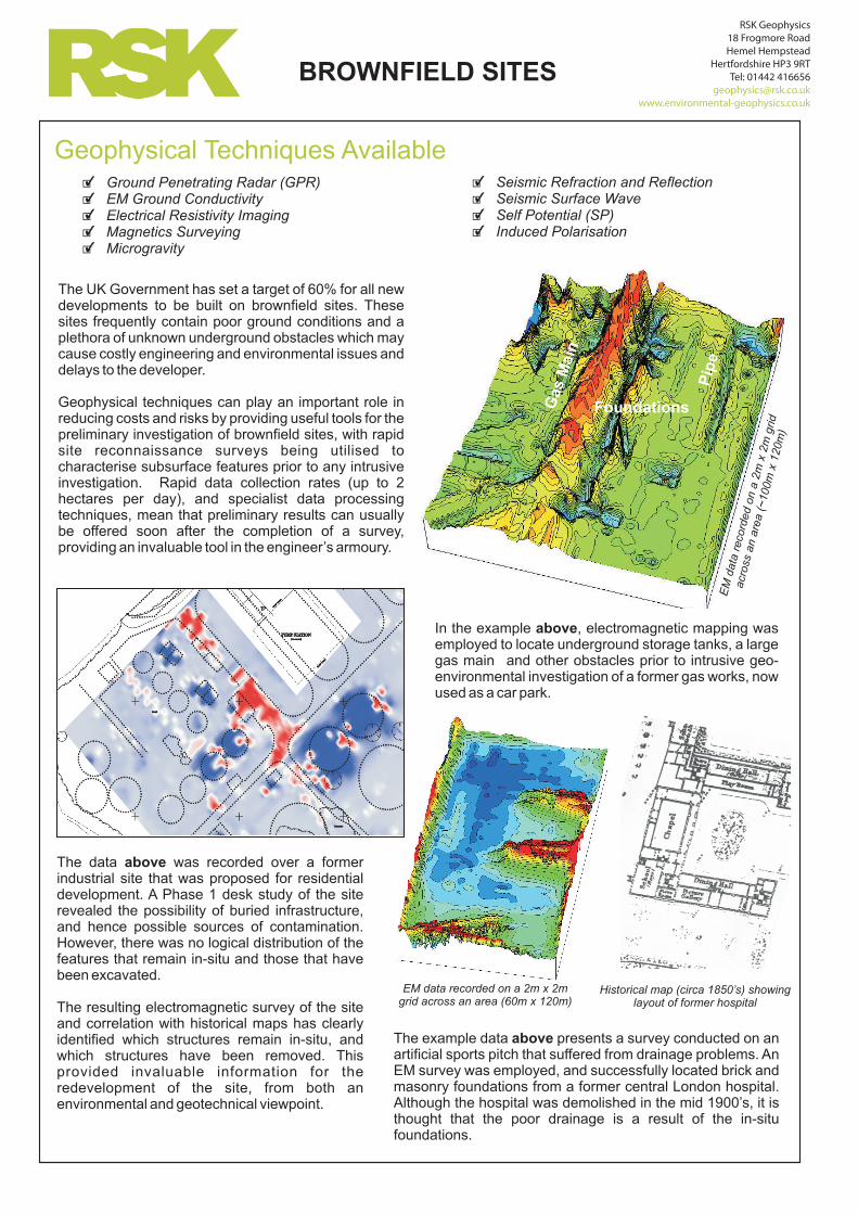
In the example above, electromagnetic mapping was employed to locate underground storage tanks, a large gas main and other obstacles prior to intrusive geo-environmental investigation of a former gas works, now used as a car park.
The data above was recorded over a former industrial site that was proposed for residential development. A Phase 1 desk study of the site revealed the possibility of buried infrastructure, and hence possible sources of contamination. However, there was no logical distribution of the features that remain in-situ and those that have been excavated.
The resulting electromagnetic survey of the site and correlation with historical maps has clearly identified which structures remain in-situ, and which structures have been removed. This provided invaluable information for the redevelopment of the site, from both an environmental and geotechnical viewpoint.
RSK Geophysics 18 Frogmore RoadHemel Hempstead
Hertfordshire HP3 9RTTel: 01442 416656
www.environmental-geophysics.co.uk

BROWNFIELD SITES
Former Land Use Determination
As part of geoenvironmental site investigations, determining the former landuse of a site can provide a useful base for determining the likely sources and locations of contamination and/or obstructions prior to re-development of a site. Historical maps can provide an insight into this, but do not reveal any information on whether the structures are still present or not.
Locating metal pipes using Magnetic Gradiometry
In this example to the right, the client was unaware of the location of two deep metal pipelines running beneath a supermarket car park. Geophysics was used to locate the pipelines so the proposed building extension could be built around them.
Scale (metres)
0 5 10 15
Locating buried services and obstructions
In this example to the left, EM mapping was used to offer a quick screening tool producing site-wide rapid characterisation of a derelict engineering works for the purpose of detecting underground hydrocarbon tanks for further investigation.
The EM map (left) clearly highlights problematic ground conditions and areas containing buried foundations,
utilities and storage tanks .
The data also shows how surface features such as metal fences and metal objects
such as benches and vehicles can strongly affect the data. In sites
with too much ‘interference’, anomalies from sub-
surface features may be masked and not
be detected.
A
Key features
B
C
D
E
Piled foundations
Underground tanks
Large underground gas mains
Other buried services
Metal surface features
B
B
A
C
DE
E
Data Examples
A
B
A
High amplitude linear magnetic anomalies indicative of buried metal services
High amplitude discrete anomalies caused by surface trolley parks
B
INFERRED PIPELINE ROUTE
Reds and pinks show areas of highest conductivity
RSK Geophysics 18 Frogmore RoadHemel Hempstead
Hertfordshire HP3 9RTTel: 01442 416656
www.environmental-geophysics.co.uk