Geometry Modeling and Mesh Generation Strategies for …€¦ · · 2006-02-16Geometry Modeling...
31
Geometry Modeling and Mesh Generation Strategies for Complex Three- Dimensional Iced Wing Configurations: Year 1 Report (NAG3-2562) David Thompson, Satish Chalasani, Sanka Gopalsamy, and Bharat Soni Center for Computational Systems Mississippi State University Mississippi State, Mississippi February 2002
-
Upload
nguyendien -
Category
Documents
-
view
217 -
download
3
Transcript of Geometry Modeling and Mesh Generation Strategies for …€¦ · · 2006-02-16Geometry Modeling...

Geometr y Modeling and Mesh Generation Strategies for Comple x Three-
Dimensional Iced Wing Configurations: Year 1 Repor t (NAG3-2562)
David Thompson, Satish Chalasani, Sanka Gopalsam y, and Bharat Soni
Center for Computational Systems
Mississippi State Univer sity
Mississippi State , Mississippi
Februar y 2002

Abstract
The problemof flow field simulationfor iced wing configurationsis a complex one that severely taxesexisting capabilitiesfor geometrymodeling,meshgeneration,andflow solvers. In this report,we focusonactivitiesassociatedwith thefirst yearof athree-yearprogramto developasoftwarepackageto facilitatethenumericalsimulationof viscousflows aroundicedwing configurations.We investigatedvariousgeometrymodelingandmeshgenerationtechnologiesto evaluatetheir effectivenessfor applicationto the icedwingproblem.Basedon theseevaluations,we developeda basicstrategy for attackingtheproblem.Further, wewereableto demonstratethe completeprocess—fromgeometryto meshto flow solution—fora complexicedwing configuration.
ii

Contents
1. Intr oduction 1
2. ProblemDescription 2
3. GeometryModeling 23.1 SurfaceModeling . . . . . . . . . . . . . . . . . . . . . . . . . . . . . . . . . . . . . . . . 2
3.1.1 Fully Three-DimensionalSurfaceModeling . . . . . . . . . . . . . . . . . . . . . . 43.1.2 PseudoThree-DimensionalSurfaceModeling . . . . . . . . . . . . . . . . . . . . . 4
3.2 AutomaticSurfaceExtraction. . . . . . . . . . . . . . . . . . . . . . . . . . . . . . . . . . 53.2.1 Introductionto Level Sets . . . . . . . . . . . . . . . . . . . . . . . . . . . . . . . 53.2.2 Curve (Surface)ExtractionDatausingLevel SetMethods . . . . . . . . . . . . . . 7
4. MeshGeneration 84.1 Issues . . . . . . . . . . . . . . . . . . . . . . . . . . . . . . . . . . . . . . . . . . . . . . 94.2 Procedure. . . . . . . . . . . . . . . . . . . . . . . . . . . . . . . . . . . . . . . . . . . . 94.3 ExampleMesh . . . . . . . . . . . . . . . . . . . . . . . . . . . . . . . . . . . . . . . . . 94.4 TheICEWING System . . . . . . . . . . . . . . . . . . . . . . . . . . . . . . . . . . . . . 10
4.4.1 Rationale . . . . . . . . . . . . . . . . . . . . . . . . . . . . . . . . . . . . . . . . 104.4.2 Topologically-AdaptiveSurfaceMeshGeneration. . . . . . . . . . . . . . . . . . . 124.4.3 Topologically-AdaptiveVolumeMeshGeneration. . . . . . . . . . . . . . . . . . . 124.4.4 ExampleMesh . . . . . . . . . . . . . . . . . . . . . . . . . . . . . . . . . . . . . 14
5. Flow Solution 15
6. Assessmentof Existing Capabilities 15
7. Recommendations 17
8. Summary 18
A. Truly Thr ee-DimensionalSurfaceModeling 23A.1 Createthetrailing edgecurve . . . . . . . . . . . . . . . . . . . . . . . . . . . . . . . . . . 23A.2 Createtheleadingedgecurve . . . . . . . . . . . . . . . . . . . . . . . . . . . . . . . . . . 25A.3 Split thepoint cloudinto two surfaces . . . . . . . . . . . . . . . . . . . . . . . . . . . . . 25A.4 CreateCurvesat theInboardandOutboardBoundaries . . . . . . . . . . . . . . . . . . . . 25A.5 Creationof Surfaces . . . . . . . . . . . . . . . . . . . . . . . . . . . . . . . . . . . . . . 27
iii

List of Figures
1 Noisypoint cloud data . . . . . . . . . . . . . . . . . . . . . . . . . . . . . . . . . . . . . 32 Fully thr ee-dimensionalsurfacerepresentation . . . . . . . . . . . . . . . . . . . . . . . 53 Pseudothr ee-dimensionalsurfacerepresentation . . . . . . . . . . . . . . . . . . . . . . 64 Airf oil surfaceextraction using level sets . . . . . . . . . . . . . . . . . . . . . . . . . . 85 Triangular surfacemesh(wing lower surface) . . . . . . . . . . . . . . . . . . . . . . . . 106 Left-side boundary of mesh . . . . . . . . . . . . . . . . . . . . . . . . . . . . . . . . . . 117 Meshon sideboundariesnear airf oil . . . . . . . . . . . . . . . . . . . . . . . . . . . . . 128 Cutting planesthr ough the meshat thr eespanwisestations(lower surface) . . . . . . . 139 Meshflaw in left-sideboundary plane . . . . . . . . . . . . . . . . . . . . . . . . . . . . 1410 Exampleof simple topologicaladaptivity in a surfacemesh . . . . . . . . . . . . . . . . 1511 Topologicaladaptivity for meshquality impr ovement . . . . . . . . . . . . . . . . . . . 1612 Near-body volumemeshwithout topologicaladaptivity . . . . . . . . . . . . . . . . . . 1713 Near-body volumemeshwith topologicaladaptivity . . . . . . . . . . . . . . . . . . . . 1814 Navier-Stokessolution for icedwing usingCobalt ��� M=0.3, Re=2.0x10
�, ��� ����� . . . 19
15 BasicStrategy: Generatesix curvesto definetwo surfaces . . . . . . . . . . . . . . . . . 24
iv

1. Intr oductionTherearetwo distinct applicationsrelatedto the aircraft icing problemin which computationalfluid dy-namics(CFD) canplay a significantrole [1]. First is the predictionof ice accretionusinga codesuchasLEWICE [2] coupledwith a CFD flow solver. The secondpotentialapplicationis a detailedflow fieldanalysisto determinetheeffectsof iceaccretiononaircraftperformance.Here,we focusexclusively on thesecondapplication.
In general,detailedthree-dimensionalsimulationsof theflow aroundanicedwing arerelatively raredueto theenormousexpenditureof resourcesneededto obtainaqualitysolution.Chung,et.al. [3] demonstratedthe potentialof CFD by predictingthe aerodynamiccharacteristicsof an aircraft involved in an accidentattributedto icing. The ice shapesweredeterminedfrom testsin theNASA GRCIcing ResearchTunnel.Oncea representative two-dimensionalchordwisesectionswasdiscretized,a three-dimensionalgeometrywasgeneratedby extruding the two-dimensionalice shapein thespanwisedirectionandfairing theshapeat thetip. A two-blockstructuredgrid wasgeneratedwith noncontiguousoverlappinginterfaces.Theflowfield solutionwascomputedusingthegeneral-purposecodeNPARC [4].
Recentadvancesin scanningtechnologyhave madeit possibleto generatedescriptionsof complexshapesin the form of “point clouds.” This technologyhasbeenexploited to generatethree-dimensionalpoint-clouddatafor icedwing configurations[5]. Althoughscannerstypically employ apresetscanpattern,theresultingdatacanperhapsbebestcharacterizedasunorganizedbecausetheonly connectivity informa-tion is in termsof thescanline. Further, thedataobtainedfrom a scanmaybenoisy. Existing techniquesdependsolelyon geometriccharacteristicsto reconstructa surfaceandmayhave difficulty reconstructinganonsmoothsurfacefrom noisydata[6].
Theability of geometry/meshgenerationtools to adequatelyaddresstheuniqueneedsof an icedwingflow simulationis alsomuchin question.Obviously, therearesignificantissuesrelatedto representationofthe icedwing surface. Therearealsoquestionsregardingthequality of theNURBSrepresentationof thesurface. It is obvious that somepreprocessingof the surfacewill be required. However, thereis no clearindicationat this time what type of preprocessingis neededor to what degreeit is needed.Additionally,within the constraintsof accuracy, efficiency, andflexibility , questionsremainasto what type of meshisappropriatefor acomplex iced-wingconfiguration.
In this report,we focuson activities associatedwith thefirst yearof a three-yearprogramto developasoftwarepackageto facilitatethe numericalsimulationof viscousflows aroundiced wing configurations.To date,therehave beenonly limited numericalthree-dimensionalicing-effectsstudies.Dueto this limitedexperience,thefirst yearemphasiswasplacedonidentifyingasound,overallapproachto surfacemeshgen-eration/volumemeshgeneration/flow solutionratherthandevelopingnew technologies.Theoneexceptionto this is thedevelopmentof a generalized,near-bodymeshgenerationmodule.Below is a brief summaryof activitiesaccomplishedto date:
1. An approachto generateafully three-dimensionalNURBSrepresentationof thepoint-clouddatawasdevelopedusingthe“ImagewareSurfacer”softwarepackage.
2. An approachusinga pseudothree-dimensionallofted geometryrepresentationwith the“ImagewareSurfacer”softwarepackagewasinvestigated.
3. A techniqueutilizing medicalimagingtechnologywasappliedto filter chordwiseiced-wingsections.Theapproachmetwith mixed,althoughpromising,results.
4. Severalmeshesfor icedwing configurationsweredevelopedusingtheexistingmeshgenerationpack-ageSolidMesh[7].
5. A new topologically-adaptive surfacemeshgenerationalgorithmwasappliedto theicedwing prob-lem.
1

6. A new topologically-adaptive volumemeshgenerationalgorithmwasappliedto theicedwing prob-lem.
7. A flow solutionfor anicedwing configurationwasgeneratedusingtheCobalt�� [8] flow solver.
8. Strategies were developedfor geometrymodelingand meshgenerationspecificto the iced wingproblem.
The work accomplishedto datecanbestbe divided into threecategories–geometrymodeling,meshgen-eration,andflow solution–andthe reportis organizedin this manner. A summaryof activities relevant toeachof theseareasperformedduring Year1 is describedin the sectionsthat follow. Also includedareadiscussionon theimplicationsof thework andasuggestedstrategy for icedwing CFD.
2. Problem DescriptionThe problemof generatinga computationalfluid dynamicssolution for the flow aboutan iced wing is acomplex oneinvolving severalsteps.In orderto provide motivation for theorganizationof this report,wenow provideaproblemdefinition.Givenapoint cloudrepresentationof awing with aniceaccretion:
1. Developa representationof thesurfacethatis suitablefor generatingasurfacemesh
2. Specify the artificial boundariesneededto definethe computationaldomain,e.g.,outerboundary,wake,etc.
3. Generatea meshand specify boundaryconditionson the boundingsurfacesof the computationaldomain
4. Generateameshin theinteriorof thecomputationaldomain
5. Generateaflow solution
Sinceour objective is to develop a strategy to solve this problem,the problemstatementis expressedintermsof animplementationstrategy. In thesectionsthatfollow, wewill focusonissuesrelatingto geometrymodelingandmeshgeneration.Wealsoprovideaflow solutionto demonstrateexistingcapabilities.
3. Geometr y ModelingIn thiscontext, theobjectiveof geometrymodelingis to generateaNURBSrepresentationof theicedwingfrom the scannedpoint cloud data. This NURBS representationis thenoutputasan IGES file which canbe usedasinput to a meshgenerator. The primary challengeassociatedwith the geometrymodelingis areconstructionof potentiallynoisysurfacedata.Thesoftwareusedto generatethegeometrydescriptionisthe SDRCpackage“ImagewareSurfacer” hereafterreferredto simply asSurfacer. We acquiredSurfacerundertheSDRCUniversityLicensingProgram.S.ChalasaniandS.Gopaltook part in a trainingprogramon “Imageware”conductedby SDRCApril 16-20,2001.
We first describeissuesrelatedto surfacemodeling.We thendescribetwo differenttechniquesto gen-eratea NURBSrepresentationof thepoint clouddata.Finally, we discussanautomatedfiltering procedurebasedon techniquesfrom medicalimageprocessing.
3.1 Surface ModelingAdvancesin scanningtechnologyhaveprovidedimpetusfor catalogingandcharacterizingthree-dimensional
ice accretionson aircraftwings. Shown in Figure1 is a sideview of a typical “noisy” point cloud. In addi-tion to obvious“outliers,” therearepointsrelatively nearthesurfacethatareclearlynot partof thesurface.It shouldbenotedthat thepointsneartheleadingedgethatappearto be“inside” theairfoil areactuallyin
2

Figure1: Noisypoint cloud data
“front of” and“behind” the modelin this view. Clearly, the datamustbe filtered beforeany kind of sur-facereconstructioncanbeperformed.Manualdenoisingis relatively easyto performfor two-dimensionalslicesbut is moredifficult for three-dimensionaldata. Oneapproachis to generatechordwiseslicesof thethree-dimensionaldataat differentspanwisepositions,manuallydenoisetheslicesby deletingtheoutlyingpoints,andgeneratea three-dimensionalsurfaceby lofting betweentheslices.Unfortunately, thisapproachmayadverselyaffect thefidelity of thesurfaceunlessmany chordwiseslicesareemployed.
Oncethe dataaredenoised,it is necessaryto generatea surfacerepresentationthat is homeomorphicto andlies in closegeometricproximity to theoriginal surface.This is a significanttopic in currentCAD,computergraphics,computervision, andmathematicalmodelingresearch.In theseapplications,a meshis oftengeneratedusingonly thescanneddatapoints[6]. In our applicationwe want to generatea surfaceuponwhichamesh(with acontrollablepointdistribution)canbegenerated.Simply interpolatingaNURBSsurfacemaynot bea goodapproachdueto thepotentiallyoscillatorynatureof thereconstruction.Further,theremaybeissuesrelatedto undersampleddata,i.e., insufficient resolutionin regionsof highcurvature.Itseemsthatmany fine scalefeatures(suchasroughnessandsmall“feathers”)arelikely to beundersampledby thescanner. Therefore,anadditionalscale-dependentfiltering of thedatamight alsobeappropriate.Wearenot currentlyaddressingthis issue.
In the two approachesdiscussedbelow, we considerNURBS representationsof the surface. We dothis only becausemost meshgenerationsoftware is basedon NURBS representationsof the underlyinggeometrydefinition. We now outline two generalstrategiesto generatea NURBSrepresentationfrom thepoint clouddata:a fully three-dimensionalapproachandapseudothree-dimensionalapproach.
3

3.1.1 Fully Three-Dimensional Surface ModelingIn the fully three-dimensionalapproachwe developedaspart of this effort, Surfacerwasusedto “fit” aNURBS representationto the actualpoint cloud data. The main advantageof this approachis that thethree-dimensionalnatureof theiceaccretioncanberetained.Theprimarydisadvantagesarethedifficultiesassociatedwith filtering three-dimensionalpointclouddataandthesurfacefitting itself. ThistechniqueusesSurfacerto fit aNURBSsurfaceto theicedwing datain conjunctionwith thefollowing strategy:
1. Extracttrailing edgeandleadingedgecurves.
2. Segmenttheicewing datainto two parts- wing topandwing bottom.
3. Extractsideboundarycurvesof wing topandwing bottom.
4. Fit NURBS surfacesto the wing top andbottompointsusingthe boundarycurvesandpoint clouddata.
This approachis describedin detail in theAppendix.We notethatobtainingtheboundarycurveswastimeconsumingbecauseof themanualinteractionneededto cleanup thetwo-dimensionalsections.Further, thethree-dimensionalpoint cloudneedsto bemanuallyfiltered.
A filtered three-dimensionalpoint cloud and the surfacegeneratedusing this approachareshown inFigure2. Therearesignificantoscillationsin the generatedsurfacenearthe boundarycurves. Definingcurvesthatpassnearthetips of thehornsandsplit theupperandlower surfacesinto two surfaceseachcanreducetheseoscillationsandreducethemaximumpositionerrorby morethan50%.However, thisapproachintroducesvisible slopediscontinuitiesat the surfaceintersections.Theseartificial slopediscontinuitiesoccuratcritical regionsandcouldposepotentiallyseriousproblemsfor theflow solverasfarasaccuracy ofthesolution.
3.1.2 Pseudo Three-Dimensional Surface ModelingChoo[9] suggestedanalternativeapproachthatis basedon lofting two-dimensionalchordwiseslicesof thedata.Theprimaryadvantageof thisapproachis thattheneededtwo-dimensionalslicescaneasilybefilteredto eliminatenoisydatapoints.Thedisadvantageis thatthespanwiseresolutionis limited by thenumberofmanuallygeneratedchordwiseslices. Oncetheslicesaregeneratedandfiltered,Surfaceris usedto loft asurfacebetweenthechordwiseslicesusingtheprocedureoutlinebelow:
1. Selectseveralspanwisepositions
2. Generatechordwiseslicesof thepoint cloudateachspanwisestation
3. Manually“clean” (filter) theslicesto eliminateobviouslybaddatapoints
4. Generatea loftedsurfacebetweentheslicesusingthetwo-dimensionalsections
5. GenerateaNURBSdescriptionusingSurfacer
We notethat to modela three-dimensionalsurfacewith significantspanwisevariation,it will benecessaryto employ numerousstationsacrossthespan.Figure3(a)shows themanuallydenoisedchordwiseprofilesatdifferentspanwisestationsandFigure3(b) showsawire-frameview of theloftedsurface.
4

(a)Filteredpoint cloud
(b) NURBSsurfacerepresentation
Figure2: Fully thr ee-dimensionalsurfacerepresentation
3.2 Automatic Surface ExtractionWe recentlybegandevelopmentof a routineto performautomaticfiltering of thepoint clouddatathat
hasits genesisin imageprocessing.In performingmanualfiltering of two-dimensionalchordwiseslices,NASA personnelselectonly the “innermost” points to be the surface[9]. This approachis basedon theassumptionthatdatapointsthatmustbefilteredarenot locatedbelow theactualsurface.
Wehavebeeninvestigatingtheuseof level setsto generatethis innermostcontour. In thisapproach,thevelocityfunctionusedin thelevel setformulationis definedto drivethevelocityof aspecificlevel setto zeroat thesurfaceof theairfoil. We have implementeda preliminaryversionof this approachandhave appliedto imagesof icedwing sectionsgeneratedin Surfacer. We now provide somebackgroundinformationonlevel settheoryaswell asimplementationdetailsfor thisapproach.
3.2.1 Introduction to Level SetsIn the context of curve (surface)extraction,we basicallywant to segmenta region by locatingboundingcurves, i.e., an edgedetection. However, we alsowant to extract a setof pointson this boundingcurve(surface). Much work hasbeenperformedin the field of medical imageprocessingto accomplishthistask[10–12].
5

(a)Denoisedchordwiseslices
(b) Wireframeview of loftedsurface
Figure3: Pseudothr ee-dimensionalsurfacerepresentation
The basicideabehindany level setmethodsis to performfront tracking,a tasknormally performedusinga Lagrangianformulation,usingan Eulerianformulation. The main advantageis that the level setapproachcanbeusedin two or threedimensionsmakingit possibleto performcurveandsurfaceextractions.Additionally, in the level setapproach,it is not necessaryto explicitly considertopologicalchangesin thefront. Topologicalchangesoccurimplicitly in thelevel setformulation.Wenow describehow level setscanbeappliedto imagesegmentation.Level SetBasics:Supposewe have a front thatmoveswith speed������� in thedirectionof thelocal normalto thecurve. In general,������� maydependondifferentproperties:
1. Localpropertiesof thefront - Propertiesthataredeterminedby localgeometricpropertiesof thefrontsuchascurvature.
2. Globalpropertiesof thefront - Propertiesthatdependon theshapeandpositionof thefront.
3. Independentproperties- Shapeindependentproperties.
Notethat ������� is a functionthatis neitherstrictly positive nor strictly negative. We now wantto embedthefront positionasthezerolevel setof a higherdimensionalfunction � andlink thepropagationof thefrontto theevolutionof thefunction � .
6

Westartwith thezerolevel set������������������� � (1)
Differentiatingusingthechainruleweobtain
�"!$#&%'�����(�������)���*�$+��-,�������� �/. (2)
Notethatthenormalto acurveof constant� is givenby 01� %'�3254 %6��4 sothatEq.2 canbewrittenas
�"!$#&�74 %'��4�� � (3)
where� is thevelocitycomponentof thefront normalto thecurve. This is thebasiclevel setequationgivenby Sethian[10].The Front Speed:Typically, thefront speedis a functionof a constantterm,which representsinflation (ifpositive)or deflation(if negative)andacurvaturedependenttermthatprovidesasurfacetensioneffect
�8� 9;:&<>= (4)
where <@? � is auserspecifiedconstantand = is thelocal front curvaturegivenby
=A� �"B�B"�DCEF:&G/�"B"�DCEH�DCB EF#&� EIE �DCB� C B #&� CE J*K C . (5)
How to Solve the Level Set Equation: The level set equation,Eq. 3, is a wave-typeequation. Whatis importantto noteis that, like CFD simulations,appropriatenumericalsolutionsof the level setequationshouldsatisfyanentropy condition.Theentropy conditioneffectively eliminatesdiscontinuitiesin thefront.Themethodsuggestedby Malladi, et. al [11] is to usethefirst-orderupwindschemegivenby
�"L"M3NOQP R � � LOQP R :&S�� TVUW�X��� OQP R ���Y�Z% M #�T\[Q0]�*� O^P R ���Y�_%]` (6)
where
% M � TVUW� a ` BObR �3��� C #�T\[c0 adM BObR �3��� C
#eT1U�� a ` EObR �3��� C #�Tf[c0 a M EObR �3��� C N K C
% ` � Tf[c0 a ` BObR �3��� C #�T1UW� adM BObR �3��� C
#eT\[Q0 a ` EObR �3��� C #�TVUW� a M EObR �3��� C N K C
where a MOQP R � indicatesa forward spatialdifferenceand af`O^P R � indicatesa backward spatialdifferenceof� . Higher-order“EssentiallyNonoscillatory”(ENO) upwind schemeswerealsoimplementedbut did notsignificantlyaltertheresults.Theinitial � field is definedusingthesigneddistancefunctionfrom theinitiallevel set.
3.2.2 Curve (Surface) Extraction Data using Level Set MethodsThis techniqueis well-developedfor pixel-baseddata(images).Thebasicideais to usethelevel setmethodwith onemodification: the front velocity is driven to zeroasit approachesan “edge” in the image. Herewe defineanedgeto bea significantpixel gradient.Therefore,a straightforwardapproachis to employ themodifiedlevel setequation
�"!$#�g/h/���(�)i3���74 %'��4j� �/. (8)
7

(a)Noisychordwiseslices
(b) Level sets(darkestcontouris extractedairfoil surface)
Figure4: Airf oil surfaceextraction using level sets
whereg/h/���(��i$� is a speedfunction thatapproacheszeroasthezerolevel setapproachesanedge.Possiblechoicesfor thespeedfunctioninclude
g/h/���(��i$��� 99k#l4 %&��mFnpokqr������i$���s4 (9)
andg h ���(�)i3��� t `"u_v w;xzy|{~} h x B P E���� v (10)
where mFn is a Gaussiansmoothingfunction. Althoughwe areinterestedonly in thezerolevel set,we areperformingcalculationsfor all of thelevel sets.Therefore,weneedto stoptheotherlevel setswhenthezerolevel sethasstopped.Theapproachusedhereis the“extensionvelocity” approach[10]. For a givenpoint������i$� , thespeedfunctionis givenby thespeedfunctionfor thepointon thezerolevel setclosestto ������i$� .
For point-baseddata,the techniqueis not well-developed. The basicproblemis that, for point data,thereis no edgeto detectsothatthestoppingcriteriaaredifficult to define.We have tried severalfunctionsto date(mostbasedonproximity to apoint) andnonehaveprovedwholly successful.
Thesedifficulties can be illustratedusing a simple two-dimensionalexample. Figure 4(a) shows animageof achordwisesectionof thecleanwing generatedin Surfacerincludingnoise.Figure4(b)showstheextractedlevel setswith thesurfaceof theairfoil indicatedby thedarkercontour. As is clearlyvisible in thefigure, thevelocity functiondoesnot stopat the front in theregionswherethepixelsarespacedrelativelyfar apart,i.e.,wherethepixelsdo not form an“edge.” Also notethedifficulty identifying thesharptrailingedge.This canbeattributedto therelative coarsenessof themesh.A finer meshuponwhich the level setequationis solvedwouldprovideabetterrepresentationof thetrailing edge.
4. Mesh GenerationMeshgenerationfor an icedwing geometryis a challengingproblem. In thesectionsthat follow, we firstdiscusssomeof theissuesrelatedto meshgeneration.Wethenoutlineaprocedureto generateamesh.Next,weprovide imagesof anexamplemeshgeneratedusinganexistingsoftwarepackage.Finally, weconcludewith adiscussionof thepreliminaryefforts relatedto developingtheICEWING softwarepackage.
8

4.1 IssuesFroma meshgenerationstandpoint,therearethreedriving issues.Fromthestandpointof efficiency, a
meshshouldhave: (1) asfew cells(faces)aspossible,(2) anisotropicmeshrefinement,and(3) somedegreeof automation.Sinceweareattemptingto computethesolutionfor ahighReynoldsnumber, viscousflow foracomplex three-dimensionalconfiguration,longcomputerexecutiontimesareto beexpected.However, anypotentialsavingsthatcanbegarneredthroughjudiciousmeshgenerationproceduresshouldbeconsidered.From the standpointof accuracy, a meshshouldhave: (1) point clusteringin regionsof large gradientsand(2) high quality elements(no highly skewed facesor slivers). Obviously, pointsneedto be clusteredin regionsadjacentto no-slipboundaries.Additionally, pointsneedto beclusteredin regionswherewakesmayoccur(downstreamof iceshapessuchashorns).Thismightsuggestusingsolutionadaptivemeshes.Itshouldbenotedthatsufficient resolutionmustbepresentin theinitial meshto capturethephenomenonofinterest.Somecontrol,perhapsmanual,is neededto specifyinitial pointplacements.Fromthestandpointofflexibility , themeshgenerationprocedureshouldbeableto treatverycomplex geometriesandstill producehigh quality meshes.In thenext section,we describea generalprocedureusedto generatea meshfor theicedwing problem.
4.2 ProcedureOnce the geometryrepresentationhasbeensaved in an IGES file, appropriatesurfaceand volume
meshesmustbegenerated.Thegeneralprocedurewehavedefinedis outlinedbelow:
1. Generateanunstructuredtriangularmeshon thesurfacedefinedin theIGESfile.
2. Sincewe anticipateperformingviscouscomputations,definea wake surfaceby insertinga planedownstreamof thetrailing edgecurveof thewing. Thengenerateanunstructuredtriangularmeshonthewakesurface.Finally, mergethewakesurfacemeshwith theairfoil mesh.
3. Definesideandouterboundaries.Also defineflow solverboundaryconditionson thesesurfaces.
4. Generateunstructuredtriangularmeshonall surfaces.
5. Generateanear-bodyvolumemeshfrom thesurfacemeshes.
6. Generatea tetrahedralvolumemeshin theinteriorof thedomaindefinedabove.
Notethatin somemeshgenerators,theextrusionandvoid filling stepsareseamlesslycombinedinto asinglestep.Wenow considerasamplemeshgeneratedusingtheSolidMesh[7] softwarepackage.
4.3 Example MeshTo illustrateexisting meshgenerationsoftware,we have usedSolidMesh[7] to generatea mixed ele-
mentprismatic/tetrahedralmeshstartingfrom an all-trianglesurfacemesh. SolidMeshwasdevelopedbyD. Marcum andA. Gaitherat the MississippiStateUniversity EngineeringResearchCenter. The meshhasapproximately1 million nodes,6.7 million faces,and3 million cells. This meshwasusedto obtaina Navier-Stokessolutionwith the Cobaltflow solver. The resultsof flow solutionarediscussedin a latersection.
Figure5 shows the meshon the surfacenearice accretion. Notice the nearly isotropicnatureof themeshandthepotentiallyinefficientpointdistributiononthesurface.Themeshappearsto beof highquality,however. Figure6 shows themeshin the left-sideboundaryof thecomputationaldomain(theadditionallines arepart of a framearoundthe plot). The first thing to notice is that thereis no concentrationofpointsin thewake of thewing. Thewake wasnot includedin this demonstrationmesh.Themeshextendsapproximately15 chordsfrom the wing in the chordwiseandvertical directions. Detailedimagesof the
9

(a)All-triangle surfacemesh (b) Detail imageneariceaccretion
Figure5: Triangular surfacemesh(wing lower surface)
meshin the left boundaryplaneandright boundaryplaneareshown in Figures7(a)and(b), respectively.Notice the boundarylayer meshclusterednearthe no-slip boundaries. Figure 8 shows cutting planesthroughthemeshon the lower surfaceof thewing at threespanwisestations.Note thatbecausethesearecuttingplanes,theconnectivity shown in theimagesdoesnot representtheactualconnectivity of themesh.Of particularinterestin the figure is the boundarylayer meshnearthe surface. Finally, in Figure9, weshow aflaw thatwe locatedin themeshin theleft-sideboundaryplane.Noticethewidely varyingcell sizesandtheapparentcollapseof thecellsneartheboundary. At this time,we areunsureof theprecisecauseoftheproblem.Onepossibility is the fact that the ice accretionseemsto have a severeslopewith its normaldirectedtowardtheboundaryplane.
It shouldbenotedthatSolidMeshmaynot representa long-termsolutionsinceit is not public domainsoftware.We arecurrentlyinvestigatingalternative softwarepackagesfor generatingunstructuredmeshes.However, we have demonstratedthata mesh(of generallyhigh quality) canbegeneratedfor theicedwingusingexisting technology.
4.4 The ICEWING SystemOneof the specifiedfirst-yearobjectiveswas to begin developmentof a meshgenerationsystemfor
icedwing configurations.In thesectionsthatfollow, wepresenttherationalewedevelopedanddiscussourprogressto date.
4.4.1 RationaleIt appearshighly unlikely thatahighquality, multiblockstructuredmeshcanbegeneratedfor theicedwingproblemwithoutaprohibitiveexpenditureof manpower. Therefore,sometypeof unstructuredmeshis ane-cessity. Theproblemsassociatedwith anunstructuredpurelytetrahedralmeshfor viscousflow calculations–namelytheaccuracy of thehighly stretchedtetrahedrain theboundarylayerandtheinefficiency of apurelytetrahedralmesh–arewell documented[13,14]. Thesedeficienciessuggestemploying a hybrid mesh[13–15]. Hybrid mesheshave theadvantagesof bothstructuredandunstructuredmeshes.In a hybrid mesh,a
10

Figure6: Left-side boundary of mesh
highly-stretched,near-body meshis extrudedfrom the surfaceto capturelarge gradientsin the field vari-ables. Typically, the extrudedmeshis generatedusingan advancinglayer scheme.The remainderof thedomainis filled with a tetrahedralmesh.If anextrudedsurfacehasquadrilaterals,sometypeof transitionalelementis neededbetweentheextrudedmeshandthetetrahedralmesh.Typically, in a hybrid mesh,all thecellsareof standardshapes:triangularprismsandtetrahedraor hexahedra,pyramids,andtetrahedra.
Unfortunately, volumemeshesgeneratedusingadvancinglayer methodsmay have poor quality cellsnearconvex and concave regions of the geometry. To addressthis shortcomingof hybrid-type meshes,several researchershave consideredthe possibility of usingotherelementtypesto improve meshquality.Theresultingmeshes,which maycontainarbitrarypolyhedra,i.e.,no restrictionsareplacedon thenumberof edgesa facecanhaveor thenumberof facesacell canhave,havebeendubbedgeneralizedmeshes[16].In [17], edgecollapseandrefinementareusednearconcaveandconvex regionsof thegeometry, respectively,to improve themeshquality. In [18], theconceptof thegeneralizedprism is introducedto improve meshquality by controlling the resolutionof themeshnearconvex corners.In additionto theseoperations,thetransitionbetweenthe near-body meshand tetrahedralmeshshouldalsobe considered.Improved meshquality in the transitionregion canbe obtainedby having isotropiccells at the extrudedmesh/tetrahedralmeshinterface.Edgecollapseandfacerefinementmaygive therequiredisotropy in themarchingdirectionbut canspoil thequality in theextrudedsurface.Therefore,surfacecleanupmayberequiredto improve thequalityof theextrudedsurface.
The addedflexibility and potential for higher accuracy in viscousregions make generalized/hybridmeshesattractive for the iced wing problem. The current interestin hybrid meshescan be ascertainedby a review of theproceedingsof the7th InternationalConferenceon NumericalGrid Generationin Com-putationalField Simulations[19] wheretherewereno fewer thantwelve paperson thetopic of generalizedandhybrid meshgeneration.
We have recentlyintroducedtheconceptof topologicaladaptivity [20]. Topologicaladaptivity impliesusingcellsthatarelocally topologicallyappropriatebasedongeometricandsolutionrequirements.Wenowdiscusshow wehave implementedtopologicaladaptivity for surfaceandvolumemeshes.Wethenconcludewith adiscussionof integrationissues.
11

(a)Left-sideboundaryplane (b) Right-sideboundaryplane
Figure7: Meshon sideboundariesnear airf oil
4.4.2 Topologically-Adaptive Surface Mesh GenerationWe developedan algorithmto convert an all-trianglesurfacemeshto mixed triangle/quadrilateralsurfacemesh.Theadvantagein performingsucha transformationis thattheexpenseof performinga flow solutionstronglydependsonthenumberof facesin amesh.Therefore,if thenumberof facescanbereducedwithoutadverselyaffectingmeshquality, thecostof asolutioncanbereduced.Theparticularalgorithmweemployherecombinestwo trianglesif the directionsof the surfacenormalsfor eachtrianglediffer by lessthanaprescribedamount.Figure10 shows a comparisonof theall-triangularmeshgeneratedby SolidMeshwithamixed-elementmeshgeneratedby appropriatelycombiningadjacenttriangles.Theresulting37%savingsin cellsfacesis significant.Wehavenotappliedany surfacemeshsmoothingat this time.
4.4.3 Topologically-Adaptive Volume Mesh GenerationThequality of a meshgeneratedusingextrusionmethodsmaybepoornearconvex andconcave regionsofthegeometry. Figure11(a)shows anexampleof poorquality cellsneara concave region. As this meshisextruded,pooraspectratiocellswill developwhichwill resultin “slivers”beinggeneratedin thetetrahedralmesh.Onesolutionto this problemis to employ a changein the topologyof themesh.Edgecollapse,asshown in theFigure11(b),will stopthegenerationof poorqualitycellsandtherebyprovide theopportunityto extrude further into the domainand increasethe percentageof nontetrahedralelements.Figure11(c)shows poorquality cellsnearconvex regionsof thegeometry. Facerefinement,asshown in Figure11(d),canimprove thequalityof themeshby eliminatinghighly divergentcells.
Edgecollapseandfacerefinementcanalsobeusedto forcethemeshto becomemoreisotropicwhich,in turn,smoothesthetransitionto thetetrahedralmesh.However, theseoperationsmayleadto poorqualityon the top surfaceof eachlayer. Therefore,quality improvementoperationsshouldbe performedon theextrudedsurfaceaswell. Thevariousoperationsarediscussedin the following sections.The termslistedbelow areusedin thediscussionof thequality improvements:
� Aspectratio is definedastheratio of thelargestedgeto thesmallestedgein a face.This is definedfor eachfacein thetopandbasesurfaceof eachlayer.
12

(a) (b) (c)
Figure8: Cutting planesthr ough the meshat thr eespanwisestations(lower surface)
� Mar ching aspectratio is definedby edgelength in the marchingdirection to the minimum edgelengthon thebasesurface.
� Divergenceangle is definedfor eachedgeandis definedasthemaximumof thein-surfaceangles
EdgeCollapse: Theedgecollapseoperationis performedto improve thequality of themeshnearconcaveregionsandto force themeshto becomemoreisotropic. Theedgesto becollapsedareselectedusingthefollowing criteria:
� Changein aspectratio of thefacesof thesurfacemeshbeforeandafterextrusion:This ratio is usedto identify theconvergingcellsnearnon-convex regions.
� Marchingaspectratio: This ratio is usedto forcethefacesin themarchingdirectionto becomemoreisotropic.
The selectededgesaregiven priorities accordingto the marchingaspectratio andaresortedaccordingtotheassignedpriorities. Edgecollapseis performedby collapsingtheselectededgeto a point, typically themidpointof theedge.If oneof thenodesis a boundarynode,thenthis nodeis kept to maintainboundaryintegrity. Theedgecollapseprocessis initiatedat thefirst edgein thelist. To avoid performinganoperationthatresultsin aninvalid mesh,all of theedgessharingeitherof thetwo nodesof theedgeunderconsiderationaremarkedasnon-collapsibleedges.After processingthelist, thecell connectivity isupdated.Edgecollapseresultsin ageneralizedcell topology.FaceRefinement: Facerefinementis performedto improve the meshquality nearconvex regionsandtoforce themeshto becomemoreisotropic. Facesarerefinedaccordingto thenumberof edgesmarked forrefinement.Theedgesaremarkedfor refinementusingoneof thefollowing criteria:
� Divergenceangle:Thisanglequantifiesthedegreeof divergenceof meshfacesnearconvex regions.
� Marchingaspectratio: This ratio is usedto forcethefacesin themarchingdirectiontowardisotropy.
The selectededgesaregiven priority accordingto their divergenceangles.The selectedfacesarerefinedandcell connectivity is updated.Thisoperationalsoresultsin ageneralizedcell topology.Extruded SurfaceImpr ovement: Edgecollapseandfacerefinementimprove thequalityalongthemarch-ing direction. However, theseoperationsdo not take into accountthe quality of the meshin the extrudedsurface.Therefore,thequality of themeshin theextrudedsurfacemaybedegradedandimprovementsin
13

(a)Meshin left-sideboundaryplane (b) Detail of regionnearmeshflaw
Figure9: Meshflaw in left-sideboundary plane
thesurfaceareneeded.Theprocessis initiatedby identifying theminimumanglearoundeachnode.Thefollowing stepsareperformedto improve thesurfacemeshquality:
� Edgecollapse:This is doneto eliminatesmallanglecells.
� Local reconnection:Poorquality quadrilateralscanbeconvertedinto two trianglesof betterqualityandviceversa.
As the meshis generated,every stepis taken to prevent the generationof negative volumes. The al-gorithmis designedto give yield trianglesandquadrilateralson theextrudedsurface.More work is beingperformedin thegeneralareaof quality improvement.Theresultsof thesepreliminaryeffortsarepresentedin thenext section.
4.4.4 Example MeshIn this section,we demonstratethebenefitsof topologicaladaptivity for mesheson icedwings. We startedfrom the all trianglesurfacemeshshown in Figure5. We thenappliedour topologicallyadaptive surfacemeshalgorithmto combineselectedtrianglesto form quadrilaterals.In thefinal step,we usedour topolog-ically adaptive meshextrusionalgorithmto generatea nearbodymesh.Themeshspacingnearthesurfacewasintentionallychosento belargesothataclearpictureof theextrudedmeshcouldbeobtained.
Figure 12 shows a near-body volume mesh(light color) generatedby extrusion from a mixed trian-gle/quadrilateralsurfacemesh(dark color) without topologicaladaptivity. A portion of the volumemeshhasbeencut away to so that the surfacemeshis visible. In Figure12(a)we notethat the meshquality ispoor in the ridge that runsjust aft of thehorn. Similarly, in Figure12(b),we seepoorquality cells in thecenterridgeof theiceaccretionon theleadingedge.
Figure 13 shows a near-body volume mesh(light color) generatedby extrusion from a mixed trian-gle/quadrilateralsurfacemesh(darkcolor) with topologicaladaptivity. As before,a portionof thevolumemeshhasbeencut away. In Figure13(a)we notethat themeshquality is improved in the ridgeaft of thehornin comparisonwith Figure12(a).Similarly, themeshquality in theridgerunningdown thefront face
14

(a)All trianglesurfacemesh (b) Mixedtriangle/quadmesh
Figure10: Exampleof simple topologicaladaptivity in a surfacemesh
of the hornsis likewise improved asshown in Figure13(b). It shouldbe notedthat we did have somedifficulty extrudingmuchbeyondseverallayersdueto meshcrossingin aconcave region. Wearecurrentlyworking to addresstheproblemof meshcrossingusingtopologicaladaptivity.
5. Flow SolutionWe have generateda Navier-Stokessolutionon the meshshown in Figures5-9 usingCobalt�* [8] . Theflight conditionswere � �l�Y.�� , ��t��lGY.����(9Y� � , and �1�l� �j�� . Thesolutionrequiredmorethan30 hoursof wall-clock timeona96processorSGIPowerChallenge3.
Wehave investigatedtheflow field usingthevisualizationpackageFIELDVIEW [21]. Not surprisingly,theflow is largely separatedover theuppersurface. Thereis alsoa significantrecirculatingregion on thelowersurface.Streamribbontracesin theregionabovethesurfaceaft of thehornareshown in Figure14(a).A similar imagefor the region below the surfaceis shown in Figure14(b). Of particularinterestin theseimagesis thethree-dimensionalnatureof theflow separation.Eventhoughtheselectediceshapeis “mostly”two dimensional,therearesignificantspanwiseflow componentsfurtherre-enforcingtheneedfor additionalstudyof the effectsof the geometrymodelingaspectsof the problem. It shouldbe notedthat no seriousattempthasyet beenmadeto establishthevalidity of thesolution.However, theseresultsindicatethat it ispossible,usingexisting technology, to generateaNSsolutionfor anicedwing configuration.
Dueto anMPI upgradein our local system,we have beenunableto obtaina HYBFL3D [22] solution.Additionally, whenwe attemptedto computea solutionremotelyusingHYBFL3D, the solutiondivergedaftera few hundrediterations.Weattributethis behavior to theflaw in themeshshown in Figure9.
6. Assessment of Existing CapabilitiesBasedonefforts to date,wehavearrivedat thefollowing conclusions:
1. It is our opinionthatSurfaceris a goodtool for performingmany of theoperationsneededfor basicgeometrymodelingfor wings with complex ice accretions. It shouldbe noted,however, that allfiltering needsto beperformedmanually. In ouropinion,this is Surfacer’sprimaryshortcoming.
2. Thefully three-dimensionalsurfacemodelingapproachhassomedifficultiesbecausetheprocedureusedto “fit” the NURBS surfaceproducesoscillationsin the NURBS descriptionthat effectivelydistortsthespanwiseshapethethree-dimensionalapproachattemptsto preserve. Themodifiedpro-cedure,i.e., addingthe splitting curvesnearthe horn tips, reducesthe positionerror relative to the
15

(a)Poorqualitymeshnearconcave regions (b) Quality improvementvia edgecollapse
(c) Poorqualitymeshnearconvex regions (d) Quality improvementvia facerefinement
Figure11: Topologicaladaptivity for meshquality impr ovement
pointclouddatabut introducesvisibleslopediscontinuitiesin thesurface.Additionally, thisapproachis notappropriatefor datathathasnot yetbeendenoised.
3. Themaindeficiency of thepseudothree-dimensionalsurfacemodelingapproachis that,unlessnu-merousspanwisesectionsareemployed,potentiallysignificantspanwisevariationsin the ice accre-tion will not beaccuratelymodeled.Unfortunately, manualfiltering of thetwo-dimensionalsectionsis a timeconsumingprocess.
4. Regardlessof theapproachusedfor surfacemodeling,it seemsthatsometypeof automatedproce-dure is necessaryto performfiltering. The useof imageprocessingtechniquesfor this purposeispromising.
5. ThemeshgenerationpackageSolidMeshwasusedto generatea meshfor the icedwing configura-tion. While therewasa flaw in the meshon the left-sideboundaryof the computationaldomain,themeshappearedto beof generallygoodquality. However, SolidMesh,which is typicalof unstruc-tured/hybrid meshgenerators,doesn’t providetheintuitivecontrolfor pointpositioningthatis neededfor theicedwing problem.
6. Thetopologicallyadaptivesurfaceandvolumemeshesappearto havepromise.However, muchworkstill needsto be doneto improve the quality of the extrudedsurface. Additionally, the problemof
16
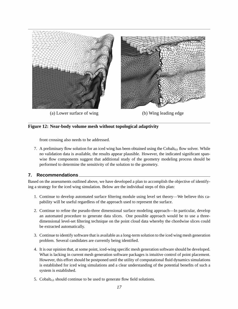
(a)Lowersurfaceof wing (b) Wing leadingedge
Figure12: Near-body volumemeshwithout topologicaladaptivity
front crossingalsoneedsto beaddressed.
7. A preliminaryflow solutionfor anicedwing hasbeenobtainedusingtheCobalt�� flow solver. Whileno validationdatais available,theresultsappearplausible.However, theindicatedsignificantspan-wise flow componentssuggestthat additionalstudy of the geometrymodelingprocessshouldbeperformedto determinethesensitivity of thesolutionto thegeometry.
7. RecommendationsBasedon theassessmentsoutlinedabove,wehavedevelopedaplanto accomplishtheobjectiveof identify-ing astrategy for theicedwing simulation.Below aretheindividual stepsof this plan:
1. Continueto developautomatedsurfacefiltering moduleusinglevel settheory—We believe this ca-pability will beusefulregardlessof theapproachusedto representthesurface.
2. Continueto refinethepseudo-threedimensionalsurfacemodelingapproach—Inparticular, developan automatedprocedureto generatedataslices. One possibleapproachwould be to usea three-dimensionallevel-setfiltering techniqueon thepoint clouddatawherebythechordwiseslicescouldbeextractedautomatically.
3. Continueto identifysoftwarethatisavailableasalong-termsolutionto theicedwingmeshgenerationproblem.Severalcandidatesarecurrentlybeingidentified.
4. It isouropinionthat,atsomepoint,iced-wingspecificmeshgenerationsoftwareshouldbedeveloped.Whatis lackingin currentmeshgenerationsoftwarepackagesis intuitivecontrolof pointplacement.However, thiseffort shouldbepostponeduntil theutility of computationalfluid dynamicssimulationsis establishedfor icedwing simulationsanda clearunderstandingof thepotentialbenefitsof suchasystemis established.
5. Cobalt�� shouldcontinueto beusedto generateflow field solutions.
17

(a)Lowersurfaceof wing (b) Wing leadingedge
Figure13: Near-body volumemeshwith topologicaladaptivity
6. Evaluatetheeffectivenessof computationalfluid dynamicstechniquesfor icedwing simulationsbycomparisonof computedresultswith experimentaldata.
7. Determine,by comparisonwith experimentaldata,if the significantspanwiseflow componentsre-portedhereare real featuresratherthan computationalanomalies. If they are real, determinethesensitivity of thespanwiseflow componentson theresolutionof surfacemodel.
8. Summar yThe problemof flow field simulationfor iced wing configurationsis a complex one that severely taxesexistingcapabilitiesfor geometrymodeling,meshgeneration,andflow solution.In thefirst yearof a three-yeareffort, we investigatedvariousgeometrymodelingandmeshgenerationtechnologiesto evaluatetheireffectivenessfor applicationto the iced wing problem. Basedon theseevaluations,we developeda basicstrategy for attackingtheproblemandwereableto demonstratethecompleteprocess—fromgeometrytomeshto flow solution—foracomplex icedwing configuration.
Surfacerwasusedfor all geometrymodelingactivities. Startingfrom apointcloudrepresentationof theicedwing surface,wedevelopedatechniqueto generateafully three-dimensionalNURBSrepresentationofthepointcloud.However, thisapproachcanonly beappliedto relatively cleandataandmanualdenoisingofthethree-dimensionalpoint cloudcanbechallenging.We alsoinvestigateda geometrymodelingtechniquebasedon lofting two-dimensionalchordwisesections.Thisapproachfacilitatesmanualcleanupof thetwo-dimensionalsection. However, if significantvariationof the ice shapeoccursin the spanwisedirection,many sectionsareneededto accuratelymodelthesurface.Giventheselimitations,bothtechniquesperformadequately. Furtherstudyis neededto determinetheimportanceof thespanwisevariationin theice shape.TheNURBSrepresentationis outputasanIGESfile.
SolidMeshwasusedto generatea triangularsurfacemeshfrom the NURBS representation.A mixedprismatic/tetrahedralmeshwasthengenerated.Themeshappearsto beof goodquality with theexceptionof a region on the left-sideboundaryof the computationaldomain. However, SolidMeshreally doesnotprovide intuitivecontrolof pointplacementthatmaybenecessaryfor icedwing flow field calculations.We
18

(a)Uppersurfacestreamlines
(b) Lowersurfacestreamlines
Figure14: Navier-Stokessolution for icedwing usingCobalt ��� M=0.3, Re=2.0x10�, �����X�3���
alsoappliedour topologicallyadaptive surfaceandvolumemeshgenerationalgorithmsto the iced wingproblem.In general,wefoundthat,while they havemuchpromise,thesealgorithmsstill requiremoreworkbeforethey canberoutinelyappliedto thesecomplex problems.
A flow field solution was computedusing Cobalt�� . While there is no experimentaldata to verify
19

thesolution,it appearsreasonable.Thereis massive flow separationon theuppersurfaceanda significantrecirculatingregiononthelowersurface.Thecomputedresultsshow asignificantspanwiseflow component.Theeffectsof thegeometrymodelon thesespanwiseflow componentsneedsto beevaluated.
20

References
[1] Y. Choo,K. D. Lee,D. S.Thompson,andM. Vickerman.GeometryModelingandGrid Generationfor”Icing Effects”and”Ice Accretion”SimulationsonAirfoils. P. R. Eiseman,J.Hauser, B. K. Soni,andJ.F. Thompson,editors,Proc. 7!�� International Conference on Numerical Grid Generation in Compu-tational Field Simulations, pages1061–1070.InternationalSocietyfor Grid Generation,MississippiState,MS, September2000.
[2] W. B. Wright. UserManualfor theNASA GlennIceAccretionCodeLEWICE 2.0. TechnicalReportCR-1999-209409,NASA, September1999.
[3] J.Chung,Y. Choo,A. Reehorst,D. W. Sheldon,andJ.Slater. NumericalStudyof Aircraft Controlla-bility underCertainIcing Conditions.AIAA Paper 99-0375, AIAA 37!�� Aerospace Sciences Meeting,Reno,NV, January1999.
[4] NPARC user’sguideversion3.0,1996.
[5] Y. Choo.privatecommunication,June2000.
[6] T. K. Dey, J.Giesen,S.Goswami,J.Hudson,R. Wenger, andW. Zhao.UndersamplingandOversam-pling in SampleBasedShapeModeling. Proc. IEEE Visualization 2001, pages83–90,2001.
[7] D. Marcum. UnstructuredGrid GenerationusingAutomaticPoint InsertionandLocal Reconnection.J. F. Thompson,B. K. Soni, andN. Weatherill,editors,Handbook of Grid Generation. CRC Press,BocaRaton,FL, 1998.
[8] R. F. Tomaro,W. Z. Strang,andL. N. Sankar. An Implicit Algorithm for Solving Time-DependentFlows on UnstructuredGrids. AIAA Paper 97-0333, AIAA 35!�� Aerospace Sciences Meeting, Reno,NV, January1997.
[9] Y. Choo.privatecommunication,June2001.
[10] J.A. Sethian.Level Set Methods and Fast Marching Methods: Evolving Interfaces in ComputationalGeometry, Fluid Mechanics, Computer Vision, and Materials Science. CambridgeUniversity Press,secondedition,1999.
[11] R. Malladi, J. A. Sethian,andB. C. Vemuri. ShapeModeling with Front Propagation: A Level SetApproach.IEEE Trans. Pat. Anal. Mach. Int, 17(2):158–175,February1995.
[12] R.Malladi andJ.A. Sethian.A Real-TimeAlgorithm for MedicalShapeRecovery.Proc. InternationalConference on Computer Vision, pages304–310,January1998.
[13] J.A. Shaw. Hybrid Grids. J.F. Thompson,B. K. Soni,andN. Weatherill,editors,Handbook of GridGeneration. CRCPress,BocaRaton,FL, 1998.
[14] J.A. Chappell,J.A. Shaw, andM .Leatham.TheGenerationof Hybrid GridsIncorporatingPrismaticRegions for ViscousFlow Calculations. M. Cross,P. R. Eiseman,J. Hauser, B. K. Soni, andJ. F.Thompson,editors,Proc. 5!�� International Conference on Numerical Grid Generation in Computa-tional Field Simulations, pages537–546.InternationalSocietyfor Grid Generation,MississippiState,MS, September1996.
[15] Y. Kallinderis. Hybrid GridsandTheir Applications.J.F. Thompson,B. K. Soni,andN. Weatherill,editors,Handbook of Grid Generation. CRCPress,BocaRaton,FL, 1998.
21

[16] D. S. Thompsonand B. K. Soni. SemistructuredGrid Generationin Three-Dimensionsusing aParabolicMarchingScheme.AIAA Paper 2000-1004, AIAA 38!�� Aerospace Sciences Meeting, Reno,NV, January2000.
[17] M. Leatham,S.Stokes,J.A. Shaw, J.Cooper, J.Appa,andT. A. Blaylock. AutomaticMeshGenera-tion For Rapid-ResponseNavier-StokesCalculations.AIAA paper 2000-2247, Fluids 2000 Conferenceand Exhibition, Denver, CO,June2000.
[18] A. CaryandT. Michal. GeneralizedPrismsfor ImprovedGrid Quality. AIAA paper 2001-2552, 15!��AIAA Computational Fluid Dynamics Conference, Anaheim,CA, June2001.
[19] P. R. Eiseman,J. Hauser, B. K. Soni, andJ. F. Thompson,editors,Proc. the 7!�� International Con-ference on Numerical Grid Generation in Computational Field Simulations. InternationalSocietyforGrid Generation,MississippiState,MS, September2000.
[20] S. Chalasani,D. Thompson,andB. Soni. TopologicalAdaptivity for MeshQuality Improvement.Proc. 8!�� International Conference on Numerical Grid Generation in Computational Field Simulations(submitted), June2002.
[21] FIELDVIEW User’sGuideVersion6.0,1999.
[22] R. P. Koomullil andB. K. Soni. GeneralizedGrid Techniquesin ComputationalField Simulation.M. Cross,P. R. Eiseman,J. Hauser, B. K. Soni,andJ. F. Thompson,editors,Numerical Grid Gener-ation in Computational Fluid Simulations, pages521–531.InternationalSocietyfor Grid Generation,MississippiState,MS, 1998.
22

Appendix A: Trul y Three-Dimensional Surface Modeling
This appendixdescribesthefive stepsneededto generatea fully three-dimensionalNURBSrepresentationof icedwing point clouddata.Themainobjective is to createtwo distinctsurfaces,i.e., thetop andbottomsurfaces.Thesetwo surfaceshave commonboundariesat thetrailing edgeandat anartificial leadingedge.The basicapproachis to createa setof curves that will assistSurfacerin the NURBS definition. Thesecurveswill alsobehelpful in maintaining� continuityat thecommonsurfaceboundaries.In thefollowingreport,a bold font is usedto identify Surfacerbuttonsandan italic font is usedto identify asthe entitiescreatedin Surfacer.
Thetopsurfaceis createdby designatingthefollowing curvesasboundariesof thepoint cloud:
� Trailing edge curve
� Top zmin curve
� Leading edge curve
� Top zmax curve .
Thebottomsurfaceis createdby designatingthefollowing curvesasboundariesof thepoint cloud:
� Trailing edge curve
� Bottom zmin curve
� Leading edge curve
� Bottom zmax curve .
Thetwo surfacesmatchatcommoncurvesat thetrailing edgeandtheleadingedgewith � continuity. Fig-ure15 illustratesthenotationemployedhere.TheNURBSrepresentationis outputin the IGESformatsothat it canbeimportedinto mostmeshgenerationsoftware.Theunstructuredmeshis generatedaftercom-bining the two surfaceswith themeshgenerationpackage.The following stepsexplainsthemethodologyfor creatingthesix curves.
A.1 Create the trailing edge curveThefollowing methodologyis employedto createthetrailing edge curve.
� Import the whole point cloud into the currentviewport. Changethe point cloud display to scattermodeif it is not in thescattermodeby goingto Display/Point andselectingthe scatter button.
� Changethenameof thepoint cloudto whole by goingto Basic/ChangeName.
� Orienttheview of whole point cloudby usingkeyboardbuttonF5.
� Extractthecross-sectionof thepoint cloudat thetrailing edgeusing Point/Cr oss-section/Parallel.
� This will bring up a smalldialogbox. Click theList button. This will show theall point clouddatacurrentlyvisible, i.e., thewhole cloud.Selectthewhole point cloud.
� SelecttheX-dir ection in thedialogbox.
23

Figure15: BasicStrategy: Generatesix curvesto definetwo surfaces
� Click on theStart Point buttonandto returnyour focusto themainscreen.Youwill seeawhite linewith a point on it. Decidewherethetrailing edgeis. Placethecursorin this locationandclick. Thewhite line movesto that location. This white line is a cross-sectionalplane.It will passthroughthewholepoint cloudandcreatenew point cloudat thatcross-section.
� Useonly onesection.Click on theApply button.
� Thiswill createanew pointclouddatacalledWhole SectCld. Changethenameto trailing edge cloud.
� Make the whole point cloud datainvisible so that you canconcentrateonly on trailing edge cloud.Thiscanbedoneby Display/Point/Invisible
� Changethe trailing edge cloud scattermodeto polyline modeby going to Display/Point/Displayandselectingthepolylinemode.
� Zoomin to oneendof thepoint cloudandstartpanningto examinetheclouddata.
� If any loopsappearin thepoint cloud,thenthepoint clouddatahasto cleaned.
� If so,cleanupmayincludereorderingandremoving few pointsandcanbeaccomplishedasfollows:Checkhow the pointsareorganizedby changingthe scattermodeto polyline for the trailing edgecloud. If thepointsarenot in order, reorderthepointsby goingto Points/Order/By Dir ection. SelectZ in thedirectionboxbeforeapplying.If still thereareany loopsthenremove thepointscausingtheloopsby goingto Points/Modify/Pick DeletePoints.
� Fit a curve to thepoint cloudby usingtheCurve/Createw/Clouds / Fit FreeForm option. Thiswill opena small dialog box. Choosethe cloud from the List . Input 50 a the numberof controlpointsand4 astheorder. Click Apply to fit thecloudwith thecurve.
� Changethenameof thecurveby goingto Basic/Changenameandenteringtrail edge curve.
24

A.2 Create the leading edge curveThefollowing techniqueis usedto extracttheleading edge curve.
� Makethetrailing edge cloud invisible. ThiscanbedoneusingDisplay/Points/Display andselectingthetrailing edge cloud in the List with thevisible buttonoff.
� Now put the whole point clouddatawith the trailing edge curve in F1 view by pressingkeyboardbuttonF1.
� Thepoint clouddataat the leadingedgehasto beextractedto definethe leading edge curve . Thiscanbedoneby goingto Points/Crosssections/Parallel. A dialogbox opensup. In thedialogbox,selectthe whole cloud andset the Number of Sectionsequalto one. Selectthe Y button in theDirection box. Therewill be white planeappearingbelow the wing wherethe default start pointexists.To changethestartpoint,click on theStart Point in thedialogboxandbring thefocusto themainscreen.Placethecursornearthestagnationpoint of theleadingedgeandclick. Theplanewillmove to thatpoint.
� Click on theApply button.This will generatepoint clouddatawhich will have somepointsnearthetrailing edgeregion. Thesepointsaredeletedby Cir cleSelectoption.
� Putthewhole cloudin invisiblemodeto concentrateon theleadingedgecloud.Changethenameofthecloudto leading edge cloud.
� Checkthepoint orderingby changingthescattermodeto polyline for the leading edge cloud. Per-form cleanupif required.
� ChooseFit FreeForm from theCurve/Curvew/Clouds to fit thecurve for theleadingedgecloud.Input 50 asthe Number of Control Points and4 asthe Order . Click Apply to fit thecloudwiththecurve. Changethenameto leading edge curve.
A.3 Split the point cloud into two surfaces� Hide all thedatakeepingwhole point clouddata,leading edge curve andtrailing edge curve in theviewport.
� Presskeyboardbutton F1 to orient the point cloud. This will be helpful in splitting the cloud in totwo parts.
� UseCir cleSelectwith option KeepBoth the Data checkedto split thecloud.
� Click thecursoron thetrailing edge curve andat theleading edge curve andform theloop to breakthecloud.
� Changethenamesof thetwo resultingpoint cloudsto top andbottom for futurereference.
A.4 Create Curves at the Inboard and Outboard BoundariesThissectiondescribesthemethodologyfollowedto extractthetop zmax curve. Thefollowing explains
themethodfollowedto generatethecloudcorrespondingto top zmax curve.
� Putall thecloudsinto invisiblemodeexcepttopcloud.
� Orientthetopcloudto F5 view by pressingkeyboardbuttonF5.
25

� Thepoint clouddatacanbeextractedby goingto Point/ Cross-section/Parallel. In thedialogboxselectthe top cloud from the List . In the Dir ection selectZ. Click on the Start Point andbringthefocusto themainscreen.A planewill bedisplayedon thescreenwhich maynot lie on or touchthecloud.Click at theplacewheretheplanepassesacrossthetopcloudin orderto getthemaximumnumberof boundarypointsandmakesuretheplaneis not toomuchinsideor outsidethecloud.
� Selectone sectionand click on Apply. This will createa new point cloud data. Changethenameto top zmax cloud temp. One can notice the top zmax cloud temp will not touch the lead-ing edge curve nearthefarandleadingedgeintersection.
� Now put the top zmax cloud temp into polyline modeandcheckif thereareany loops. If thereareany loops,cleanthecloudto removetheloops.In thepolylinemode,cleanupthetop zmax cloud tempby removing thepointswhich arecausingthis if the top zmax cloud temp is not entirely followingthecloud.
� After cleaningup the top zmax cloud temp selecta small region of top cloud nearthe intersectionof leadingedgeandtop zmax cloud temp with Cir cle Selectoption. Putthe top cloudinto invisiblemode.
� Thiswill createanew cloud.Breakthesurfaceinto two partsat theturningpointby puttingthecloudin F1 (keyboardbutton)view by usingCir cleSelectwith keepingbothoption.
� Fit asurfaceto bothof thenew clouds.Thiscanbedoneby goingto Surface/Createw/ Cloud / FitFreeForm. In thedialogbox selectthenew cloudcreated.Setthe Order to be4 andthe Numberof Control Points to be10 in bothdirections.TheFitting Dir ection asBestFit Plane. Keepall theotherdataasdefault.
� After obtainingthe two surfacesextract theboundarycurve of thesurfaceswhich will help in con-nectingthe leadingedgeto top zmax cloud temp. This canbedoneby going to Curve/ Create3Dfr om Surface / Surface boundary curve. Click on the sidesof the two surfaceboundaries.Thiswill createthecurves.Convert theboundarycurvesto 50samplepoints.Performcleanupoperationsif requiredto both the clouds. Now add the two small cloudsto one and then add this one withtop zmax cloud temp to form onecloud. Changethenameof this to top zmax cloud. Beforeaddingthe two cloudscheckthe startingandendingpoint of the cloudswhich will be helpful later whilecreatingthe curve. If the endingpoint of top zmax cloud temp andstartingpoint of newly createdsamplepointsarenot consecutive thenchangetheorderof thepoint cloudby Points / Order / SetStart Point.
� Checktop zmax cloud with polylinemodeanddonecessaryclean-upif thereareany loops.
� Createthe curve with Curve / Fit w/Cloud / Fit FreeForm. Give Number of Control Points to100and Order as4. Thiswill createanew curve.
� Thecurvemaynotextendall throughandhit theleadingedgebut it will beverycloseto it.
� Changethenameof thecurve to top zmax curve.
Theremaining3 curvesTop zmin curve, Bottom zmin curve andBottom zmax curve areextractedusingtheproceduredescribedabove.
26

A.5 Creation of SurfacesAfter generatingall 6 curves,thefirst surface(top) is fitted to the top cloudusingfollowing curvesas
theboundaries:
� Trailing edge curve
� Top zmin curve
� Leading edge curve
� Top zmax curve .
Thesurfacecanbefitted by giving thenumberof controlpointsasinput or acceptingtheoptimalnumberof controlpointsgivenby Surfacer. Thelevel of accuracy of thedescriptionof theNURBSsurfacecanbevariedusingthesmoothness,tensionandstandarddeviation parameters.Onehasto becarefulin varyingtheparametersasthesensitivity to thechangein theseparametersis high. In thecurrentapproachthevaluesusedare0.75(tension),0.5(smoothness)and0.5(standarddeviation).
Similarly thesecondsurface(bottom) is fitted to thebottom cloudconsideringthe following curvesastheboundaries:
� Trailing edge curve
� Bottom zmin curve
� Leading edge curve
� Bottom zmax curve .
After gettingthetwo surfaces,� continuity is verifiedat theleadingandtrailing edge.If they arenot� continuous,they canbe forcedto be so by matchingthe two surfacesat the interface. Oncethe twosurfacesarematched,they aresavedin IGESformat.
TheSurface-Clouddifferenceplot indicateswherethe NURBS fit doesa poor job matchingthe pointcloud. If themaxiumumerroris nearthehorntips,oneapproachfor reducingtheerroris to createanaddi-tionalcurvealongthehorntip. Thiscanbedoneby creatinga line by picking two pointson top zmin curve& top zmax curve at the turning points. After generatingthe line, it canbe projectedonto the cloud byPoints/ Crosssections/Project curve on cloud. This will give a setof pointson thecloud. Fit thecurvewith thesepointsandbreakthe top cloudat theturningpoint into two clouds.Fit thetwo surfaceswith thenewly createdcurveasaninterfaceboundary.
27