Geometry & light: the science of invisibility - qmmrc.net · Geometry & light:! the science of...
59
Geometry & light: the science of invisibility Ulf Leonhardt SCNU & Weizmann Institute
Transcript of Geometry & light: the science of invisibility - qmmrc.net · Geometry & light:! the science of...

!!!
Geometry & light:!the science of invisibility!
"Ulf Leonhardt"
SCNU & Weizmann Institute!

Geometry and Light!

Review on transformation optics!
NATURE MATERIALS | VOL 9 | MAY 2010 | www.nature.com/naturematerials 387
REVIEW ARTICLEPUBLISHED ONLINE: 23 APRIL 2010!|!DOI: 10.1038/NMAT2743
A spatially changing refractive index leads to changes in light-propagation characteristics. !e most common example is a lens, which is a curved piece of glass that bends light as
the light experiences a single change of refractive index through the air/glass interface. A medium with a continuously changing refrac-tive index can bend light to create amazing illusion e"ects, such as the mirage e"ect in deserts. Recently it was realized that arti#cial media that have spatially changing optical properties can bend light in almost any manner. !e most remarkable example is the so-called invisibility cloak1,2 that can steer light around an object to make it seem invisible. !e mathematical technique that enables us to design such arti#cial materials is called transformation optics1,2. Initially driven by the possibility of realizing the invisibility cloak, transformation optics has now evolved into a powerful tool for designing a wide variety of new optical e"ects and devices, some of which have already been created, whereas others are possible with the aid of metamaterials.
To understand how transformation optics works, let us consider light propagation over a small distance Δx in a material with refrac-tive index η. !e phase change in that distance is given by (ω/c)ηΔx, where ω is the angular frequency and c is the speed of light. We can alternatively write the phase change as (ω/c)Δx , where Δx = ηΔx represents a scale change that preserves the phase of the light and hence its propagation characteristics. Now suppose that η is a func-tion of the spatial coordinate, that is, η(x). !en changes in scale, or local transformations, can occur everywhere. Such a correspondence between materials parameters (refractive index) and the coordinate system can become useful if it is reformulated in a mathematically rigorous manner. For example, it is shown3 that two-dimensional (2D) electromagnetic problems with complex geometries (say a curved wave guide) can be solved by performing a conformal map-ping of coordinates so that the geometry becomes simple (say a straight wave guide), while the refractive index pro#le is changed to a more complex pro#le, with the refractive index at each point changed by a scale factor that is the ratio of the di"erential lengths of the two sets of coordinates. In this way a coordinate transformation results in a new η(x). Such correspondence between materials and coordinate transformation is a special property of Maxwell’s equations that gov-ern the propagation of light: these equations maintain the same form (so-called form invariance) under a coordinate transformation4–10 and thereby guarantee the physical character of light propagation to be upheld at the di"erential scale. !is characteristic is the basis of transformation optics.
In general, Maxwell’s equations at a #xed frequency can be written as8:
! E + H = 0, ! H – E = 0
Transformation optics and metamaterialsHuanyang Chen1*, C. T. Chan2 and Ping Sheng2
Underpinned by the advent of metamaterials, transformation optics o!ers great versatility for controlling electromagnetic waves to create materials with specially designed properties. Here we review the potential of transformation optics to create functionalities in which the optical properties can be designed almost at will. This approach can be used to engineer various optical illusion e!ects, such as the invisibility cloak.
If a coordinate transformation x = x (x) is applied, the equations maintain the same form8 in the transformed coordinate system
E H H E
!e permittivity tensor (ε ) and permeability tensor (μ ) in the transformed coordinate system are related to the original ε and μ and by the relationships6,8
(1)
where Λαα = ∂x α /∂xα denotes the Jacobian transformation matrix
between the virtual space and the original space8. As early as 1961, the correspondence between coordinate trans-
formations and materials parameters had already been noted11. However, until about two decades ago, such correspondence was generally regarded as a mathematical technique rather than a topic for physical research. !e reason is simple: from equation (1) it is clear that the transformed dielectric permittivity and magnetic per-meability tensors can take on almost any local value, as the Jacobian transformation matrix is a mathematical object and, as such, is not subject to physical constraints. !e close link to physics and engi-neering occurred with the advent of metamaterials12,13, which not only broadened the realm of possible values for both the dielectric constant and magnetic permeability to the negative territory, but also extended their combined e"ect in generating negative refrac-tive indices14–19. !e possibility of realizing the parameter changes dictated by equation (1) may now be seriously entertained.
In 1975 it was shown that a small ellipsoid consisting of a core and a coating can have zero dipole scattering cross-section20. It was then reported that a negative-permittivity shell can make a positive-permittivity core invisible to external #elds in the quasi-static limit21, an e"ect that was subsequently found to be able to cloak discrete dipoles within a certain distance outside the shell22. Later, in 2005, it was shown that the scattering cross-section of a small particle can be reduced by a negative-permittivity shell23, which is a form of approximate invisible cloaking for electromagnetic waves. In 2003, it was demonstrated that push-forward mapping24,25 (see Box 1) can be used to design an anisotropic conductivity that renders a region undetectable by electrical impedance tomography. !is is e"ectively an invisibility device in the quasi-static limit. In fact, the same push-forward mapping approach was later used to achieve invisibility for electromagnetic waves2.
Two independent studies in 2006 showed that for ray optics1 and electromagnetic waves2 it is possible to engineer invisibility cloaks by guiding light around a region of space as if nothing is there. !ese reports initiated a whole series of activities that brought
1School of Physical Science and Technology, Soochow University, Suzhou, Jiangsu 215006, China, 2Department of Physics and William Mong Institute of Nano Science and Technology, Hong Kong University of Science and Technology, Clear Water Bay, Hong Kong, China. *e-mail: [email protected]
nmat_2743_MAY10.indd 387 14/4/10 13:38:10
© 20 Macmillan Publishers Limited. All rights reserved10
Provided for non-commercial research andeducational use only. Not for reproduction,
distribution or commercial use.
This chapter was originally published in the book Progress in Optics. The copy attachedis provided by Elsevier for the author’s benefit and for the benefit of the author’s
institution, for non-commercial research, and educational use. This includes withoutlimitation use in instruction at your institution, distribution to specific colleagues,
and providing a copy to your institution’s administrator.
All other uses, reproduction and distribution, including without limitation commercialreprints, selling or licensing copies or access, or posting on open internet sites, your
personal or institution’s website or repository, are prohibited. For exceptions,permission may be sought for such use through Elsevier’s permissions site at:
http://www.elsevier.com/locate/permissionusematerial
From Ulf Leonhardt and Thomas G. Philbin, Transformation Optics andthe Geometry of Light.
In: Emil Wolf, editor, Progress in Optics, Vol. 53.The Netherlands: Elsevier, 2009, pp. 69–152.
ISBN: 978-0-444-53360-9© Copyright 2009 Elsevier B.V.
Elsevier
CHAPTER2Transformation Optics and theGeometry of Light
Ulf Leonhardt* and Thomas G. Philbin†
Contents 1 Introduction 702 Fermat’s Principle 743 Arbitrary Coordinates 80
3.1 Coordinate Transformations 803.2 The Metric Tensor 833.3 Vectors and Bases 853.4 One-Forms and General Tensors 853.5 Coordinate and Non-Coordinate Bases 873.6 Vector Products and Levi–Civita Tensor 883.7 The Covariant Derivative of a Vector 903.8 Covariant Derivatives of Tensors and of the Metric 953.9 Divergence and Curl 983.10 The Laplacian 993.11 Geodesics and Curvature 100
4 Maxwell’s Equations 1064.1 Geometries and Media 1074.2 Transformation Media 1094.3 Wave Equation and Fermat’s Principle 1124.4 Space–Time Geometry 115
5 Transformation Media 1175.1 Spatial Transformation Media 1185.2 Perfect Invisibility Devices 1215.3 Perfect Lenses 1245.4 Moving Media 1295.5 Optical Aharonov–Bohm Effect 1325.6 Analog of the Event Horizon 135
6 Conclusions 142Acknowledgments 144References 148
* School of Physics and Astronomy, University of St Andrews, North Haugh, St Andrews KY16 9SS, UK† Max Planck Research Group Optics, Information and Photonics, Günther-Scharowsky Str. 1, 91058
Erlangen, Germany
Progress in Optics, Volume 53, ISSN: 0079-6638, DOI: 10.1016/S0079-6638(08)00202-3.Copyright © 2009 Elsevier B.V. All rights reserved.
69
Author’s personal copy

Arabia!

Ilusions!

Mirage!

Fermat�s Principle - the principle of the shortest optical path!
€
s = n dl∫

Leonhardt 2002: Invisibility cloak?!

Nachman�s Theorem: invisibility is impossible!
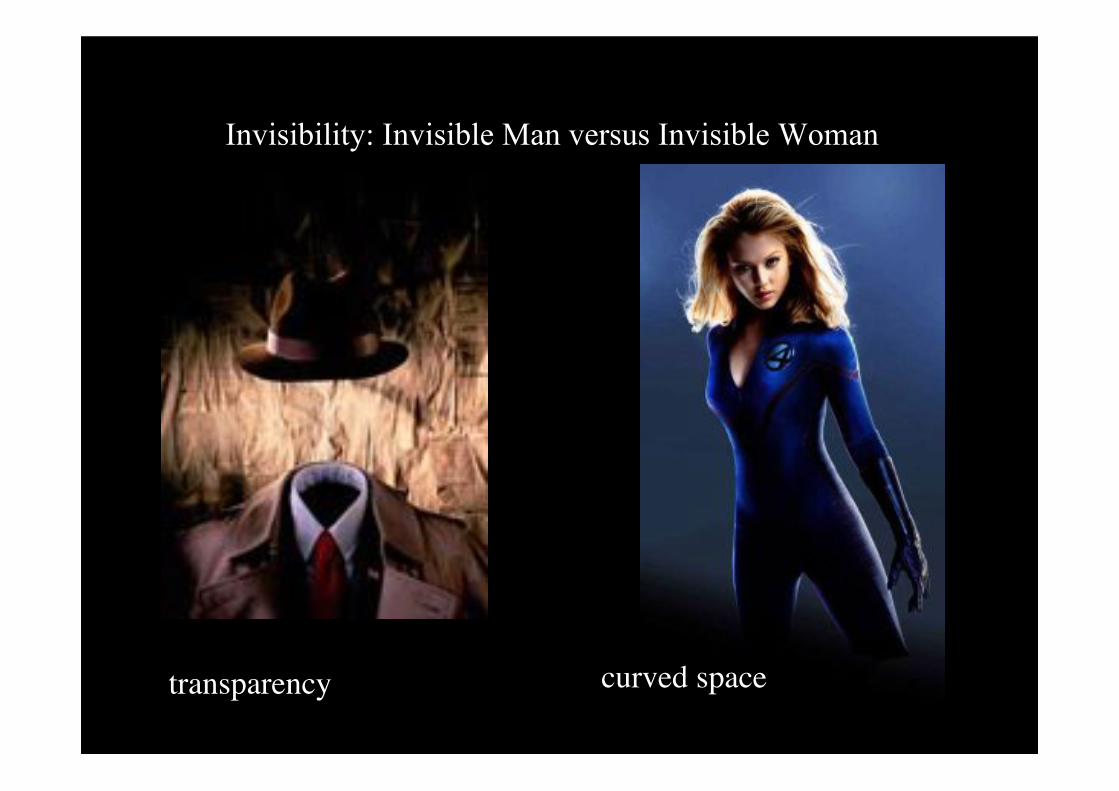
Invisibility: Invisible Man versus Invisible Woman!
transparency! curved space!

Fermat�s Principle - the principle of the shortest optical path!
€
s = n dl∫
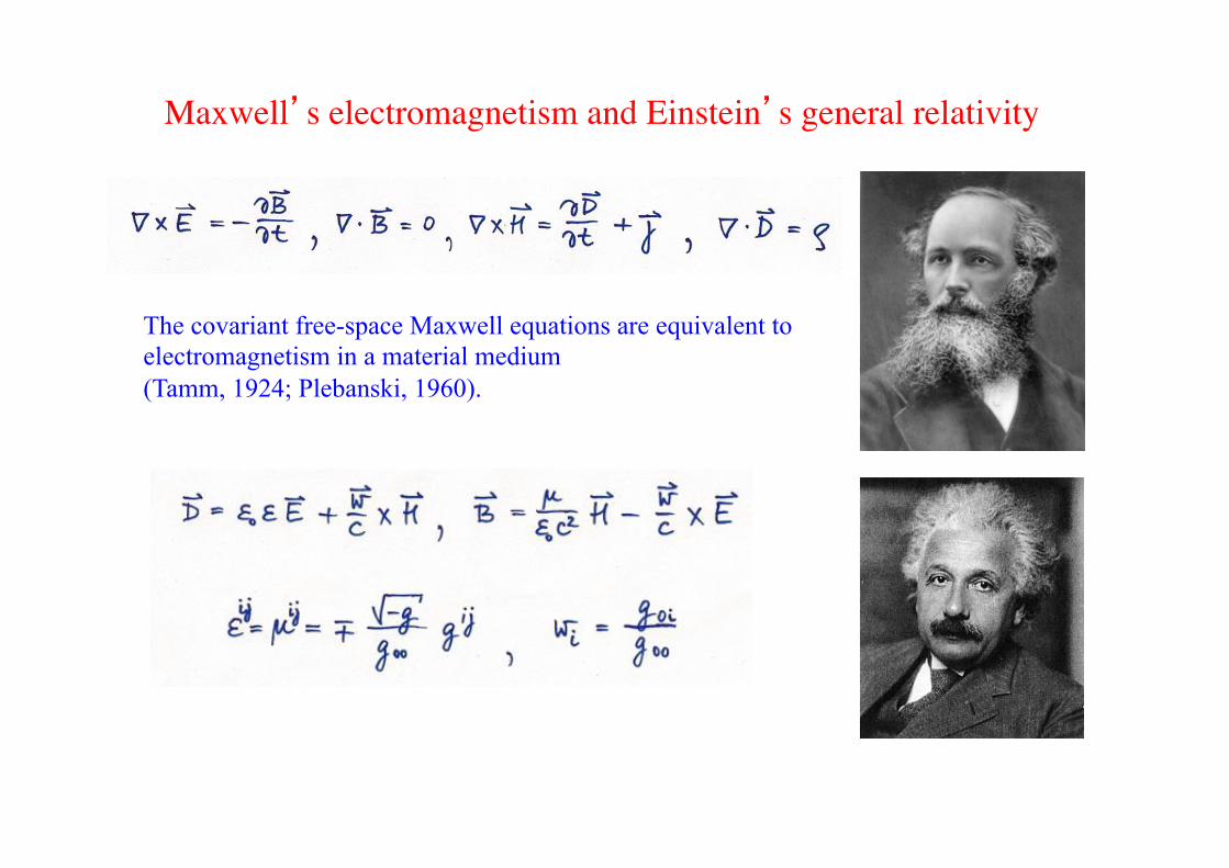
Maxwell�s electromagnetism and Einstein�s general relativity!
The covariant free-space Maxwell equations are equivalent to electromagnetism in a material medium (Tamm, 1924; Plebanski, 1960).

Refraction in ordinary medium!

Refraction in ordinary medium: virtual image depends on viewpoint!

Transformation medium!

Transformation medium: definite virtual image!

Transformation medium!
Virtual space! Physical space!

Transformation medium!
Virtual space! Physical space!

Conformal!
Virtual space! Physical space!
[Leonhardt, Science 312, 1777 (2006)]

Transformation!
Virtual space! Physical space!
[Pendry, Schurig and Smith, Science 312, 1780 (2006)]

Maxwell�s electromagnetism and Einstein�s general relativity!
The covariant free-space Maxwell equations are equivalent to electromagnetism in a material medium (Tamm, 1924; Plebanski, 1960).

Patent office!

Cloaking device for electromagnetic microwaves!

Transformation optics!
[Greenleaf, Lassas and Uhlmann, Math. Res. Lett. 10, 685 (2003) electrostatics;!Leonhardt, Science 312, 1777 (2006) conformal transformations;!Pendry, Schurig and Smith, Science 312, 1780 (2006) spatial transformations;!Leonhardt and Philbin, NJP 8, 247 (2006)] space-time & negative refraction]!

Challenge: Broadband invisibility!
Problems: * anomalous dispersion, * infinite speed of light at inner lining [Leonhardt and Philbin, New J. Phys. 8, 247 (2006)].
Ideas from Non-Euclidean Geometry

Optical deformation aka carpet cloaking: from fugu to flatfish!

3D and optical implementation!
[Science 328, 337 (2010)]
!Three-Dimensional Invisibility Cloakat Optical WavelengthsTolga Ergin,1,2*† Nicolas Stenger,1,2* Patrice Brenner,2 John B. Pendry,3 Martin Wegener1,2,4
We have designed and realized a three-dimensional invisibility-cloaking structure operating atoptical wavelengths based on transformation optics. Our blueprint uses a woodpile photoniccrystal with a tailored polymer filling fraction to hide a bump in a gold reflector. We fabricatedstructures and controls by direct laser writing and characterized them by simultaneoushigh–numerical-aperture, far-field optical microscopy and spectroscopy. A cloaking operation witha large bandwidth of unpolarized light from 1.4 to 2.7 micrometers in wavelength is demonstratedfor viewing angles up to 60°.
As today’s nanofabrication capabilitiescontinue to improve, we are better ableto address the inverse problem of electro-
magnetism with respect to what nanostructurewill perform a requested functionality. In thisregard, transformation optics (1–14) is a uniqueand intuitive scientific tool that allows for themathematical mapping of desired distortions ofspace onto an actual distribution of opticalmaterial properties in normal Cartesian space.Tailored inhomogeneous metamaterials enableus to approximate these target distributions.Invisibility-cloaking structures (1–16) can serveas benchmark examples for the much broaderideas of transformation optics.
So far, invisibility-cloaking experiments at mi-crowave (5, 10) and optical frequencies (11–14)have been performed exclusively in two-dimensional(2D) waveguide geometries. In other words, thesestructures are immediately visible from the thirddimension. Cloaking works only in the plane; theviewing angle is effectively zero in one direc-tion. Nevertheless, these structures have supportedthe validity of the concepts of both transformationoptics and metamaterials.
We designed, fabricated, and characterized3D invisibility-cloaking structures using tai-lored, dielectric face-centered–cubic (fcc) wood-pile photonic crystals. We studied the behaviorof these structures from wavelengths near thewoodpile rod spacing (where the onset of dif-fraction of light leads to the Wood or Rayleighanomaly in transmittance and reflectance) up towavelengths much larger than this spacing (theeffective-medium limit).
In the carpet-cloak geometry (8, 10–13), abump in a metallic mirror is hidden by adding atailored refractive-index distribution on top. This
distribution can be calculated using the rulesof transformation optics (8, 10). Though orig-inally designed for two dimensions, it hasbeen shown (by numerical rendering of photo-realistic images via ray tracing) that the carpet-cloak concept should also work in a truly 3Dsetting and also for very large viewing angles(17). In our 3D blueprint (Fig. 1A), the bumpis translationally invariant along the z directionand follows y(x) = hcos2(px/w) for |x| ! w/2 andzero otherwise. Here, h = 1 mm is the height ofthe bump, and w = 13 mm is its full width. Forthe quasi-conformal mapping of the cloak, wechoose a width of 26 mm in the x direction and10 mm in the y direction. This cloak is sur-rounded by a homogeneous woodpile struc-ture, which is characterized in fig. S5 (18).Inside the cloak, the local effective refractiveindex is controlled via the volume filling frac-tion ( f ) of the polymer serving as constituentmaterial for a usual woodpile photonic crystal(19, 20). The diamond-symmetry woodpile ge-ometry is chosen because it is expected to leadto nearly isotropic optical properties. The effectiverefractive index becomes n = 1.52 for f = 1 (bulkpolymer) and n = 1.00 for f = 0 (air void). Forintermediate values of f, we used the Massachu-setts Institute of Technology Photonics-Bandspackage (21) to evaluate the effective local re-fractive index (Fig. 1B) on the basis of usualphotonic-band–structure calculations. We foundthat the calculated 3D isofrequency contoursare very nearly spherical in the long-wavelengthlimit (see inset in Fig. 1B).
Figure 2 shows the target refractive-indexdistributions obtained from the quasi-conformalmapping (8) and corresponding electron mi-crographs of some of our structures made bystandard direct laser writing lithography (20, 22).
1Institut für Angewandte Physik, Karlsruhe Institute of Technology(KIT), D-76128 Karlsruhe, Germany. 2DFG–Center for FunctionalNanostructures, KIT, D-76128 Karlsruhe, Germany. 3BlackettLaboratory, Imperial College London, London SW7 2AZ, UK.4Institut für Nanotechnologie, KIT, D-76021 Karlsruhe, Germany.
*These authors contributed equally to this work.†To whom correspondence should be addressed. E-mail:[email protected]
Fig. 1. (A) Blueprint of our 3D carpet-cloak structure. The 3D cone oflight corresponding to the NA = 0.5 microscope lens is shown in red. (B)The local polymer volume filling fraction f of a woodpile photonic crystalcomposed of rods controls the effective local refractive index n. The black,red, and blue curves correspond to rod aspect ratios (= height/width) of 1, 2,and 3, respectively. The polymer needs to be connected, as do the air voids.These conditions impose lower and upper bounds on f, shown here for a rodaspect ratio of 2. The range of accessible values of n is restricted to be within1.00 (air) and 1.52 (bulk polymer). The filling fraction is actually controlled by
the number of voxels (N ! {0,3,4,5,6}) that each rod is composed of. The caseof N = 3 is illustrated by the inset in the lower right corner. For this case andfor a vacuum wavelength of 2.4 mm and a rod spacing of 0.8 mm, the upperleft inset depicts the nearly spherical isofrequency surface in wave-vectorspace.
www.sciencemag.org SCIENCE VOL 328 16 APRIL 2010 337
REPORTS
on
Sept
embe
r 29,
201
1w
ww
.sci
ence
mag
.org
Dow
nloa
ded
from
Three-Dimensional Invisibility Cloakat Optical WavelengthsTolga Ergin,1,2*† Nicolas Stenger,1,2* Patrice Brenner,2 John B. Pendry,3 Martin Wegener1,2,4
We have designed and realized a three-dimensional invisibility-cloaking structure operating atoptical wavelengths based on transformation optics. Our blueprint uses a woodpile photoniccrystal with a tailored polymer filling fraction to hide a bump in a gold reflector. We fabricatedstructures and controls by direct laser writing and characterized them by simultaneoushigh–numerical-aperture, far-field optical microscopy and spectroscopy. A cloaking operation witha large bandwidth of unpolarized light from 1.4 to 2.7 micrometers in wavelength is demonstratedfor viewing angles up to 60°.
As today’s nanofabrication capabilitiescontinue to improve, we are better ableto address the inverse problem of electro-
magnetism with respect to what nanostructurewill perform a requested functionality. In thisregard, transformation optics (1–14) is a uniqueand intuitive scientific tool that allows for themathematical mapping of desired distortions ofspace onto an actual distribution of opticalmaterial properties in normal Cartesian space.Tailored inhomogeneous metamaterials enableus to approximate these target distributions.Invisibility-cloaking structures (1–16) can serveas benchmark examples for the much broaderideas of transformation optics.
So far, invisibility-cloaking experiments at mi-crowave (5, 10) and optical frequencies (11–14)have been performed exclusively in two-dimensional(2D) waveguide geometries. In other words, thesestructures are immediately visible from the thirddimension. Cloaking works only in the plane; theviewing angle is effectively zero in one direc-tion. Nevertheless, these structures have supportedthe validity of the concepts of both transformationoptics and metamaterials.
We designed, fabricated, and characterized3D invisibility-cloaking structures using tai-lored, dielectric face-centered–cubic (fcc) wood-pile photonic crystals. We studied the behaviorof these structures from wavelengths near thewoodpile rod spacing (where the onset of dif-fraction of light leads to the Wood or Rayleighanomaly in transmittance and reflectance) up towavelengths much larger than this spacing (theeffective-medium limit).
In the carpet-cloak geometry (8, 10–13), abump in a metallic mirror is hidden by adding atailored refractive-index distribution on top. This
distribution can be calculated using the rulesof transformation optics (8, 10). Though orig-inally designed for two dimensions, it hasbeen shown (by numerical rendering of photo-realistic images via ray tracing) that the carpet-cloak concept should also work in a truly 3Dsetting and also for very large viewing angles(17). In our 3D blueprint (Fig. 1A), the bumpis translationally invariant along the z directionand follows y(x) = hcos2(px/w) for |x| ! w/2 andzero otherwise. Here, h = 1 mm is the height ofthe bump, and w = 13 mm is its full width. Forthe quasi-conformal mapping of the cloak, wechoose a width of 26 mm in the x direction and10 mm in the y direction. This cloak is sur-rounded by a homogeneous woodpile struc-ture, which is characterized in fig. S5 (18).Inside the cloak, the local effective refractiveindex is controlled via the volume filling frac-tion ( f ) of the polymer serving as constituentmaterial for a usual woodpile photonic crystal(19, 20). The diamond-symmetry woodpile ge-ometry is chosen because it is expected to leadto nearly isotropic optical properties. The effectiverefractive index becomes n = 1.52 for f = 1 (bulkpolymer) and n = 1.00 for f = 0 (air void). Forintermediate values of f, we used the Massachu-setts Institute of Technology Photonics-Bandspackage (21) to evaluate the effective local re-fractive index (Fig. 1B) on the basis of usualphotonic-band–structure calculations. We foundthat the calculated 3D isofrequency contoursare very nearly spherical in the long-wavelengthlimit (see inset in Fig. 1B).
Figure 2 shows the target refractive-indexdistributions obtained from the quasi-conformalmapping (8) and corresponding electron mi-crographs of some of our structures made bystandard direct laser writing lithography (20, 22).
1Institut für Angewandte Physik, Karlsruhe Institute of Technology(KIT), D-76128 Karlsruhe, Germany. 2DFG–Center for FunctionalNanostructures, KIT, D-76128 Karlsruhe, Germany. 3BlackettLaboratory, Imperial College London, London SW7 2AZ, UK.4Institut für Nanotechnologie, KIT, D-76021 Karlsruhe, Germany.
*These authors contributed equally to this work.†To whom correspondence should be addressed. E-mail:[email protected]
Fig. 1. (A) Blueprint of our 3D carpet-cloak structure. The 3D cone oflight corresponding to the NA = 0.5 microscope lens is shown in red. (B)The local polymer volume filling fraction f of a woodpile photonic crystalcomposed of rods controls the effective local refractive index n. The black,red, and blue curves correspond to rod aspect ratios (= height/width) of 1, 2,and 3, respectively. The polymer needs to be connected, as do the air voids.These conditions impose lower and upper bounds on f, shown here for a rodaspect ratio of 2. The range of accessible values of n is restricted to be within1.00 (air) and 1.52 (bulk polymer). The filling fraction is actually controlled by
the number of voxels (N ! {0,3,4,5,6}) that each rod is composed of. The caseof N = 3 is illustrated by the inset in the lower right corner. For this case andfor a vacuum wavelength of 2.4 mm and a rod spacing of 0.8 mm, the upperleft inset depicts the nearly spherical isofrequency surface in wave-vectorspace.
www.sciencemag.org SCIENCE VOL 328 16 APRIL 2010 337
REPORTS
on
Sept
embe
r 29,
201
1w
ww
.sci
ence
mag
.org
Dow
nloa
ded
from

To invisibility and beyond!
[Leonhardt, Nature 471, 292 (2011)]

Pendry�s paper!

The resolution limit of imaging, established around 1870!
Ernst&Abbe& Carl&Zeiss& O0o&Scho0&
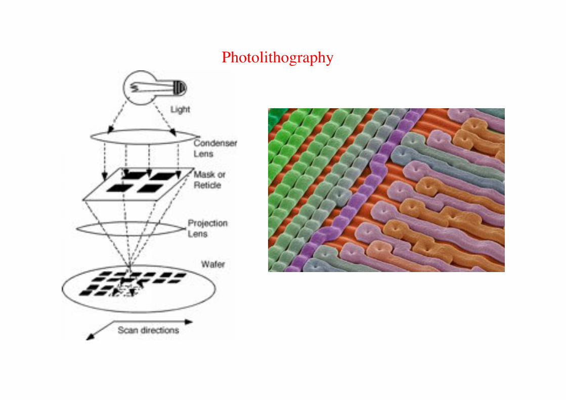
Photolithography!

Microscopy!

Pendry�s paper!
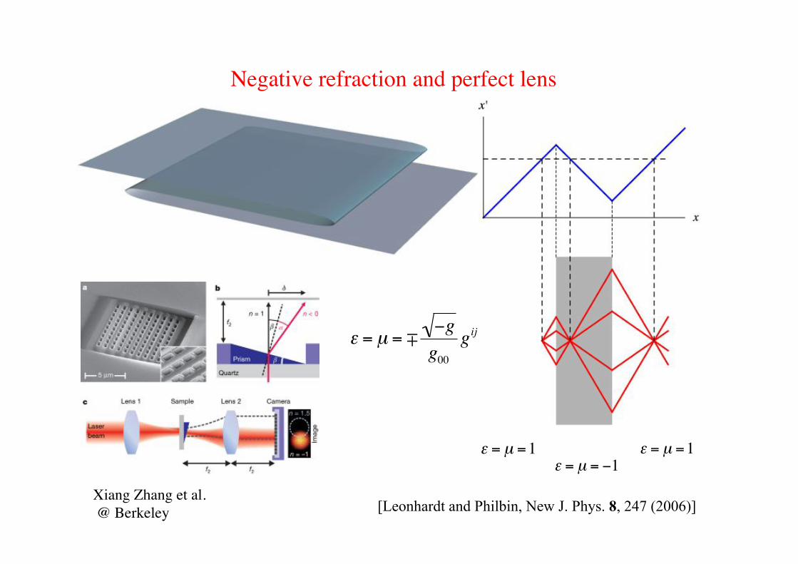
Negative refraction and perfect lens!
€
ε = µ =1
€
ε = µ = −1
€
ε = µ =1
€
ε = µ = −g
g00
gij
Xiang Zhang et al.! @ Berkeley! [Leonhardt and Philbin, New J. Phys. 8, 247 (2006)]

Controversy on perfect imaging with negative refraction!

�Poor man�s perfect lens��[Science. 308, 534 (2005)] !
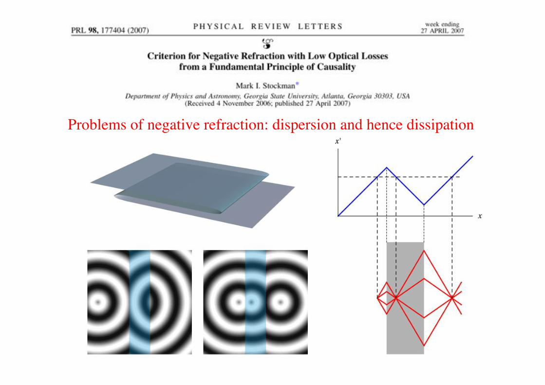
Problems of negative refraction: dispersion and hence dissipation!

Invisibility: Invisible Man versus Invisible Woman!
transparency! curved space!

Cloaking at a distance![Lai, Chen, Zhang and Chan, Phys. Rev. Lett. 102, 093901 (2009)]
Invisible slab! Invisible sphere!

The Invisible Man - cloaking at a distance![Lai, Chen, Zhang and Chan, Phys. Rev. Lett. 102, 093901 (2009)]

Section �Perfect imaging�!

Maxwell and Luneburg!

Conformal maps!

Maxwell�s fish eye makes a perfect lens "Maxwell 1854!
Luneburg 1944: Stereographic projection!

Perfect imaging without negative refraction!
2
0
2
0
/1
2
rr
nn
+= Index contrast: factor of 2!
[Leonhardt, New J. Phys. 11, 093040 (2009)]

Controversy!
Nature 480, 42-43 (1 December 2011)!

Feynman�s objection to the diffraction limit!
Maxwell�s equations are time-reversible!!But you have to inverse the source, too.!!

Perfect imaging with positive refraction for microwaves ![Ma, Sahebdivan, Ong, Tyc, Leonhardt, NJP 13, 033016 (2011)] ]
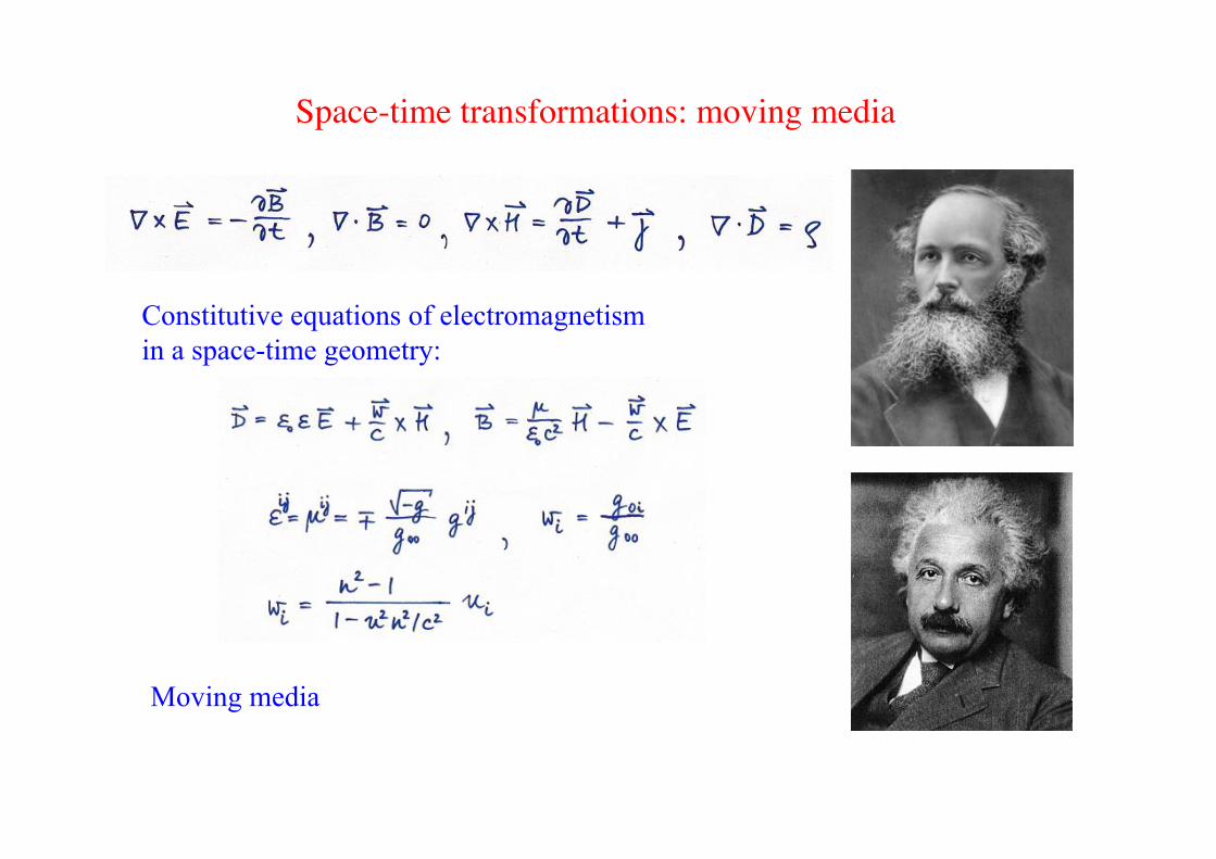
Space-time transformations: moving media!
Moving media
Constitutive equations of electromagnetism in a space-time geometry:

Space-time cloaking!
Experiment: M. Fridman et al., Nature 481, 62-43 (2012)!

Artificial black holes!

Ligh in 1D moving fluids!
Light in 1D moving media!

Artificial event horizons!
Piotr Pieranski!

Hawking radiation of black holes!

Moving fluids and pulse in fibre!
[Philbin et al., Science 319, 1367 (2008)]

Fibre-optical black holes!

General relativity in electrical engineering![Leonhardt and Philbin, New J. Phys. 8, 247 (2006)]

Einwell and Maxstein!

Geometry and Light!


![arXiv:1709.02200v1 [gr-qc] 7 Sep 2017 · Classical analogue of the Unruh effect Ulf Leonhardt 1, Itay Griniasty , Sander Wildeman2, Emmanuel Fort 2, and Mathias Fink 1Weizmann Institute](https://static.fdocuments.us/doc/165x107/5c442df493f3c34c643d1856/arxiv170902200v1-gr-qc-7-sep-2017-classical-analogue-of-the-unruh-effect.jpg)


