GEOMETRICAL ACCURACY OF HOLES AND … ACCURACY OF HOLES AND CYLINDERS MANUFACTURED WITH FUSED...
20
GEOMETRICAL ACCURACY OF HOLES AND CYLINDERS MANUFACTURED WITH FUSED DEPOSITION MODELING F. Knoop, V. Schoeppner Direct Manufacturing Research Center (DMRC), Paderborn University, Paderborn, Germany and Kunststofftechnik Paderborn (KTP), Paderborn University, Paderborn, Germany Abstract A widely used Additive Manufacturing (AM) technology is Fused Deposition Modeling (FDM) to create prototypes and end-use parts with close-to-production thermoplastics. For their use as a final product, it is necessary that additively manufactured parts strictly adhere to the geometrical requirements of the technical drawing. In this paper, the holes and cylinders of the cylindrical elements are investigated in terms of achievable geometrical accuracy. For this purpose, different test specimens that allow a measurement of inner and outer diameters from 3 to 80 mm were designed. All specimens were measured with a coordinate measuring machine (CMM) to evaluate deviations from the nominal dimension and form deviations. The measuring method includes a scanning of the surface to record the course of dimensional deviations over the diameter. Thus, it was possible to visualize how deviations on cylindrical elements manufactured in FDM occur. In order to counteract these deviations and to improve the dimensional accuracy, different shrink factors and filling patterns were investigated. Consequently, an improvement of the dimensional accuracy was achieved. Introduction Additive Manufacturing (AM) processes are characterized by a layer-by-layer material deposition so that no forming tool is necessary. It is possible to produce very complex parts which are impossible or very expensive to manufacture by conventional manufacturing processes. The starting point for every AM process is a 3D CAD model from which the layer information is generated in the data preparation [2]. Fused Deposition Modeling (FDM) is a very widespread AM process and was introduced onto the market in 1991 by Stratasys. FDM is the first additive manufacturing process that works according to the basic principle of material extrusion. After expiry of the basic patent in 2009, many open source devices entered the market, which operate in a very similar manner. The material extrusion systems still represent the largest share of all AM machines on the market [1,2]. The fundamental principle of the FDM process is based on the extrusion of polymer material through a nozzle. A pinch roller feed system above the nozzle ensures that the filament material is pushed through the nozzle and that the necessary extrusion pressure is generated [4]. The necessary energy for melting the polymer is provided by electrical heating elements. Extruded material exits the nozzle and is deposited as a thin filament by the FDM head. The FDM head is moveable in the X- and Y-directions (see Figure 1). The thermoplastic material solidifies by heat conduction and thus by cooling, resulting in a solid bonding [3,4]. After completing a part layer, the build platform is lowered by the thickness of a layer. A support material is used to join parts to the build sheet and to support overhangs or cavities. The support material is applied by means of a second nozzle and can be removed either mechanically or chemically after the process [7]. 2757 Solid Freeform Fabrication 2017: Proceedings of the 28th Annual International Solid Freeform Fabrication Symposium – An Additive Manufacturing Conference Reviewed Paper
Transcript of GEOMETRICAL ACCURACY OF HOLES AND … ACCURACY OF HOLES AND CYLINDERS MANUFACTURED WITH FUSED...
GEOMETRICAL ACCURACY OF HOLES AND CYLINDERS MANUFACTURED WITH FUSED DEPOSITION MODELING
F. Knoop, V. Schoeppner
Direct Manufacturing Research Center (DMRC), Paderborn University, Paderborn, Germany and Kunststofftechnik Paderborn (KTP), Paderborn University, Paderborn, Germany
Abstract
A widely used Additive Manufacturing (AM) technology is Fused Deposition Modeling (FDM) to create prototypes and end-use parts with close-to-production thermoplastics. For their use as a final product, it is necessary that additively manufactured parts strictly adhere to the geometrical requirements of the technical drawing. In this paper, the holes and cylinders of the cylindrical elements are investigated in terms of achievable geometrical accuracy. For this purpose, different test specimens that allow a measurement of inner and outer diameters from 3 to 80 mm were designed. All specimens were measured with a coordinate measuring machine (CMM) to evaluate deviations from the nominal dimension and form deviations. The measuring method includes a scanning of the surface to record the course of dimensional deviations over the diameter. Thus, it was possible to visualize how deviations on cylindrical elements manufactured in FDM occur. In order to counteract these deviations and to improve the dimensional accuracy, different shrink factors and filling patterns were investigated. Consequently, an improvement of the dimensional accuracy was achieved.
Introduction
Additive Manufacturing (AM) processes are characterized by a layer-by-layer material deposition so that no forming tool is necessary. It is possible to produce very complex parts which are impossible or very expensive to manufacture by conventional manufacturing processes. The starting point for every AM process is a 3D CAD model from which the layer information is generated in the data preparation [2]. Fused Deposition Modeling (FDM) is a very widespread AM process and was introduced onto the market in 1991 by Stratasys. FDM is the first additive manufacturing process that works according to the basic principle of material extrusion. After expiry of the basic patent in 2009, many open source devices entered the market, which operate in a very similar manner. The material extrusion systems still represent the largest share of all AM machines on the market [1,2]. The fundamental principle of the FDM process is based on the extrusion of polymer material through a nozzle. A pinch roller feed system above the nozzle ensures that the filament material is pushed through the nozzle and that the necessary extrusion pressure is generated [4]. The necessary energy for melting the polymer is provided by electrical heating elements. Extruded material exits the nozzle and is deposited as a thin filament by the FDM head. The FDM head is moveable in the X- and Y-directions (see Figure 1). The thermoplastic material solidifies by heat conduction and thus by cooling, resulting in a solid bonding [3,4]. After completing a part layer, the build platform is lowered by the thickness of a layer. A support material is used to join parts to the build sheet and to support overhangs or cavities. The support material is applied by means of a second nozzle and can be removed either mechanically or chemically after the process [7].
2757
Solid Freeform Fabrication 2017: Proceedings of the 28th Annual InternationalSolid Freeform Fabrication Symposium – An Additive Manufacturing Conference
Reviewed Paper
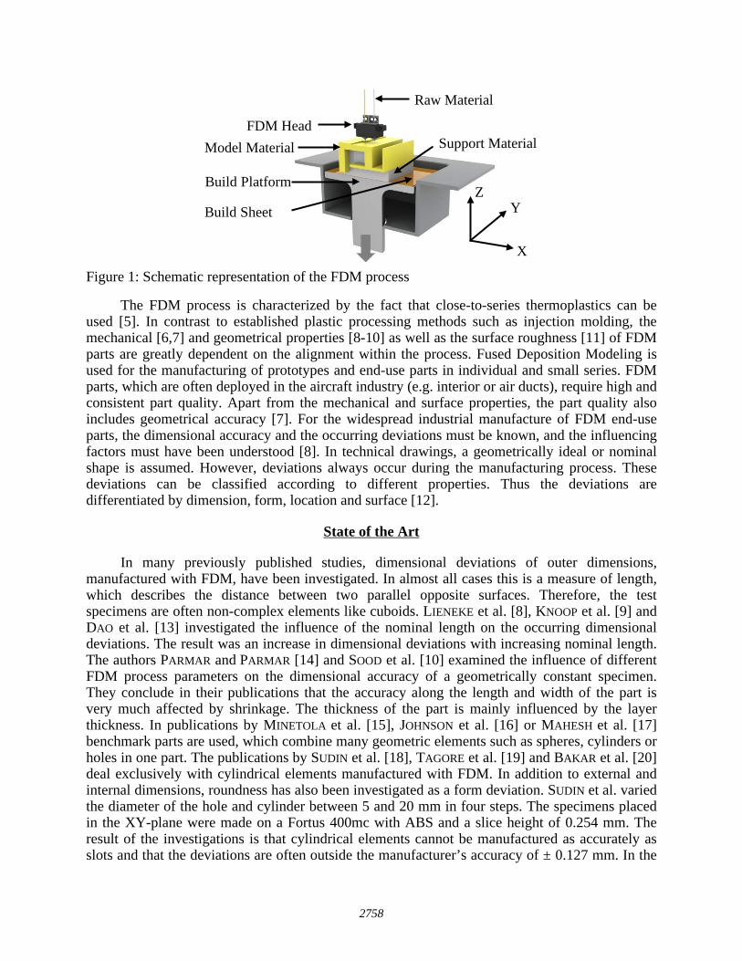
Figure 1: Schematic representation of the FDM process
The FDM process is characterized by the fact that close-to-series thermoplastics can be used [5]. In contrast to established plastic processing methods such as injection molding, the mechanical [6,7] and geometrical properties [8-10] as well as the surface roughness [11] of FDM parts are greatly dependent on the alignment within the process. Fused Deposition Modeling is used for the manufacturing of prototypes and end-use parts in individual and small series. FDM parts, which are often deployed in the aircraft industry (e.g. interior or air ducts), require high and consistent part quality. Apart from the mechanical and surface properties, the part quality also includes geometrical accuracy [7]. For the widespread industrial manufacture of FDM end-use parts, the dimensional accuracy and the occurring deviations must be known, and the influencing factors must have been understood [8]. In technical drawings, a geometrically ideal or nominal shape is assumed. However, deviations always occur during the manufacturing process. These deviations can be classified according to different properties. Thus the deviations are differentiated by dimension, form, location and surface [12].
State of the Art
In many previously published studies, dimensional deviations of outer dimensions, manufactured with FDM, have been investigated. In almost all cases this is a measure of length, which describes the distance between two parallel opposite surfaces. Therefore, the test specimens are often non-complex elements like cuboids. LIENEKE et al. [8], KNOOP et al. [9] and DAO et al. [13] investigated the influence of the nominal length on the occurring dimensional deviations. The result was an increase in dimensional deviations with increasing nominal length. The authors PARMAR and PARMAR [14] and SOOD et al. [10] examined the influence of different FDM process parameters on the dimensional accuracy of a geometrically constant specimen. They conclude in their publications that the accuracy along the length and width of the part is very much affected by shrinkage. The thickness of the part is mainly influenced by the layer thickness. In publications by MINETOLA et al. [15], JOHNSON et al. [16] or MAHESH et al. [17] benchmark parts are used, which combine many geometric elements such as spheres, cylinders or holes in one part. The publications by SUDIN et al. [18], TAGORE et al. [19] and BAKAR et al. [20] deal exclusively with cylindrical elements manufactured with FDM. In addition to external and internal dimensions, roundness has also been investigated as a form deviation. SUDIN et al. varied the diameter of the hole and cylinder between 5 and 20 mm in four steps. The specimens placed in the XY-plane were made on a Fortus 400mc with ABS and a slice height of 0.254 mm. The result of the investigations is that cylindrical elements cannot be manufactured as accurately as slots and that the deviations are often outside the manufacturer’s accuracy of ± 0.127 mm. In the
FDM Head
Raw Material
Support Material
Z
X
Y
Model Material
Build Platform
Build Sheet
2758
publication of TAGORE et al. the roundness of cylinders and bores with two different diameters, which are orientated between 0° and 90° to the build plane, is considered. The measurement is carried out by means of a coordinate measuring machine (CMM) at different heights of the specimen but without an exact specification of the measuring method. BAKAR et al. manufactured five cylinders with different diameters between 10 and 15 mm without changing the alignment of the parts. The influence of the layer thickness and raster width on dimension and form deviations was determined by measuring the specimens by means of a CMM. In the above-mentioned publications, only a very small variation of the nominal diameters (up to a maximum of 20 mm) was performed so that the influence of different dimensions could not be determined. Similarly, the influence of the alignment in the build chamber or on the build platform has not been considered holistically in these publications. Furthermore, the influence of different toolpath parameters on the dimensional accuracy or roundness has not yet been covered by the literature. In conclusion, it is not possible to clarify from these investigations how deviations in cylindrical elements emerge and how deviations are distributed over the circumference.
Experimental Setup
Material and Machine This chapter describes the experimental studies that are necessary to investigate the
geometrical accuracy of holes and cylinders manufactured with FDM. The used model material is an ABS-M30 (natural color) with the corresponding support material SR-30 from Stratasys. ABS-M30 consists of 70-75 % polymer MABS (CAS No. 9010-94-0) and 25-30 % polymer SAN (CAS No. 9003-54-7) [21]. In general, ABS (as well as modified mixtures) is an amorphous thermoplastic and therefore the shrinkage is very small (0.4 to 0.7 %) in the processing process because it has no crystalline structures [22]. A Stratasys Fortus 400mc large with a build envelope of 406 x 355 x 406 mm³ (X, Y, Z) is used to manufacture the test specimens. The layer thickness is 0.1778 mm because a T12 nozzle with a bore diameter of 0.3048 mm is used. In the data processing software Insight (version 10.4), a solid filling of the parts as well as the support style “sparse” is adjusted. The filling of the part is done at an angle of 45 ° (raster angle) and this angle changes by 90 ° from one layer to the next (δ – angle). Unless otherwise specified, the toolpath parameters given in Table 1 are used. Table 1: Used toolpath and process parameters for manufacturing specimens of ABS-M30
Layer thickness
Shrink factor Contour & raster width
Raster angle δ - angle Air gap X, Y Z
0.1778 mm 1.0055 1.0059 0.3556 mm 45 ° 90 ° 0 mm
Test Specimens As mentioned at the outset, the dimensional accuracy of holes and cylinders with different
nominal diameters is to be determined in this paper. In order to cover a wide range of nominal diameters, these are derived from DIN EN ISO 286-1 and DIN 16742, respectively. These standards are used when values for basic tolerances are to be specified. From the listed nominal dimension classes in the standard, each maximum is selected. Therefore nominal diameters between 3 and 80 mm are obtained, which are used as external and internal dimensions on the test specimens (cf. Figure 2 & Figure 3). The test specimen with seven different cylinders (outer diameter) is shown in Figure 2. The cylinders with a wall thickness of 10 mm (Z-height) are arranged on a 1 mm thick base plate. The chosen arrangement results from the measurement and
2759
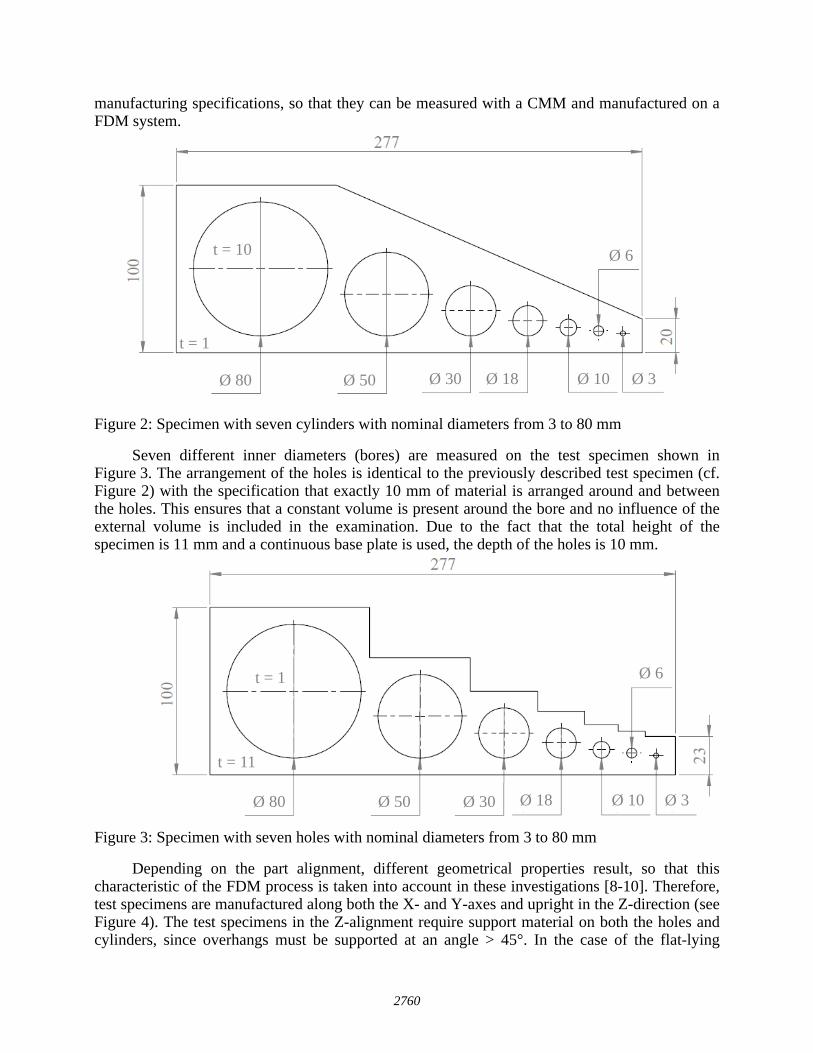
manufacturing specifications, so that they can be measured with a CMM and manufactured on a FDM system.
Figure 2: Specimen with seven cylinders with nominal diameters from 3 to 80 mm
Seven different inner diameters (bores) are measured on the test specimen shown in Figure 3. The arrangement of the holes is identical to the previously described test specimen (cf. Figure 2) with the specification that exactly 10 mm of material is arranged around and between the holes. This ensures that a constant volume is present around the bore and no influence of the external volume is included in the examination. Due to the fact that the total height of the specimen is 11 mm and a continuous base plate is used, the depth of the holes is 10 mm.
Figure 3: Specimen with seven holes with nominal diameters from 3 to 80 mm
Depending on the part alignment, different geometrical properties result, so that this characteristic of the FDM process is taken into account in these investigations [8-10]. Therefore, test specimens are manufactured along both the X- and Y-axes and upright in the Z-direction (see Figure 4). The test specimens in the Z-alignment require support material on both the holes and cylinders, since overhangs must be supported at an angle > 45°. In the case of the flat-lying
Ø 80 Ø 50 Ø 30 Ø 18 Ø 10 Ø 3
Ø 6
t = 1
t = 10
Ø 80 Ø 50 Ø 30 Ø 18 Ø 10 Ø 3
Ø 6
t = 11
t = 1
2760
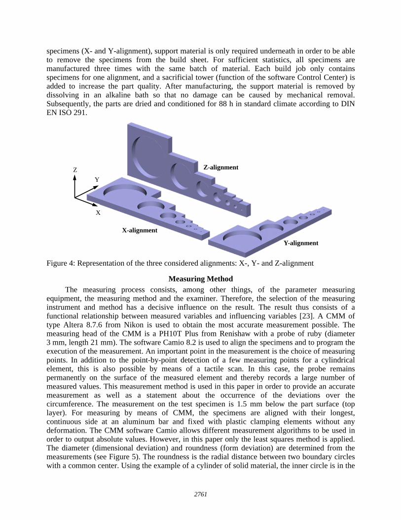
specimens (X- and Y-alignment), support material is only required underneath in order to be able to remove the specimens from the build sheet. For sufficient statistics, all specimens are manufactured three times with the same batch of material. Each build job only contains specimens for one alignment, and a sacrificial tower (function of the software Control Center) is added to increase the part quality. After manufacturing, the support material is removed by dissolving in an alkaline bath so that no damage can be caused by mechanical removal. Subsequently, the parts are dried and conditioned for 88 h in standard climate according to DIN EN ISO 291.
Figure 4: Representation of the three considered alignments: X-, Y- and Z-alignment
Measuring Method The measuring process consists, among other things, of the parameter measuring
equipment, the measuring method and the examiner. Therefore, the selection of the measuring instrument and method has a decisive influence on the result. The result thus consists of a functional relationship between measured variables and influencing variables [23]. A CMM of type Altera 8.7.6 from Nikon is used to obtain the most accurate measurement possible. The measuring head of the CMM is a PH10T Plus from Renishaw with a probe of ruby (diameter 3 mm, length 21 mm). The software Camio 8.2 is used to align the specimens and to program the execution of the measurement. An important point in the measurement is the choice of measuring points. In addition to the point-by-point detection of a few measuring points for a cylindrical element, this is also possible by means of a tactile scan. In this case, the probe remains permanently on the surface of the measured element and thereby records a large number of measured values. This measurement method is used in this paper in order to provide an accurate measurement as well as a statement about the occurrence of the deviations over the circumference. The measurement on the test specimen is 1.5 mm below the part surface (top layer). For measuring by means of CMM, the specimens are aligned with their longest, continuous side at an aluminum bar and fixed with plastic clamping elements without any deformation. The CMM software Camio allows different measurement algorithms to be used in order to output absolute values. However, in this paper only the least squares method is applied. The diameter (dimensional deviation) and roundness (form deviation) are determined from the measurements (see Figure 5). The roundness is the radial distance between two boundary circles with a common center. Using the example of a cylinder of solid material, the inner circle is in the
Z
X
Y
Z-alignment
X-alignment
Y-alignment
2761
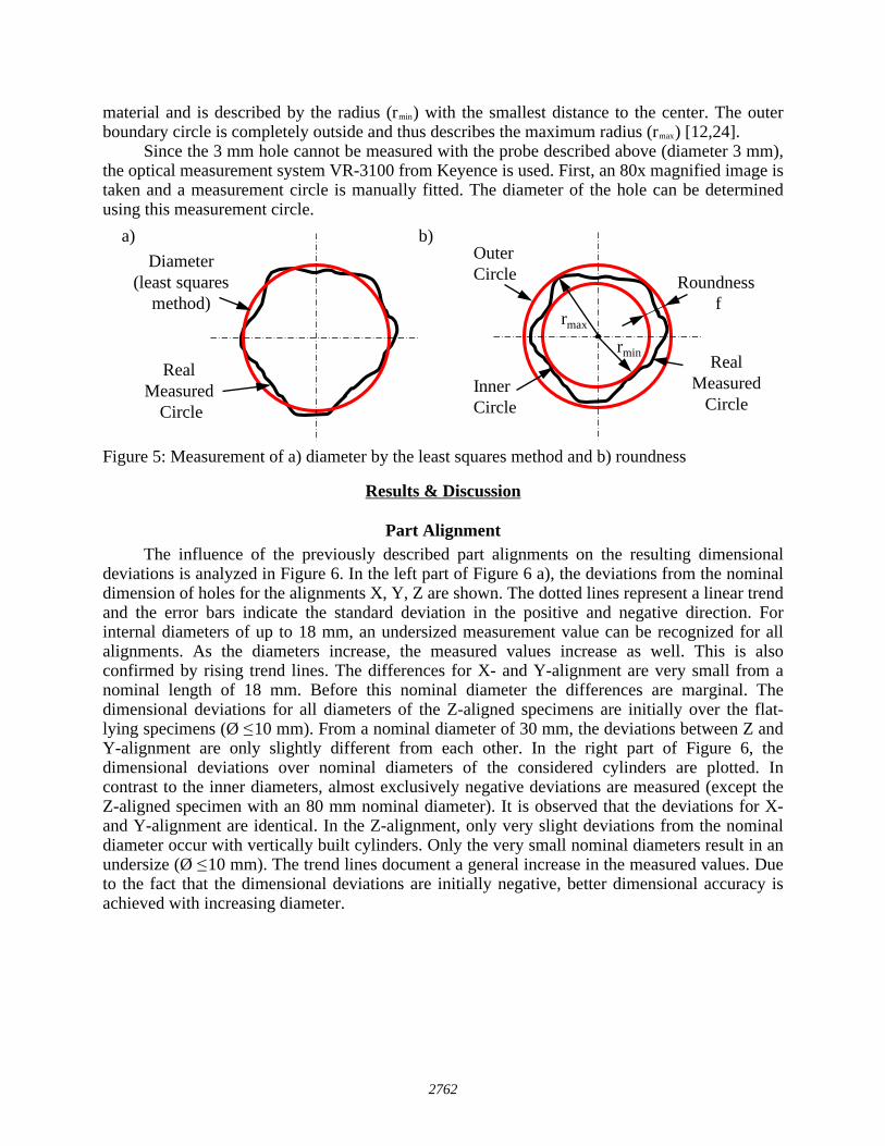
material and is described by the radius (rmin) with the smallest distance to the center. The outer boundary circle is completely outside and thus describes the maximum radius (rmax) [12,24].
Since the 3 mm hole cannot be measured with the probe described above (diameter 3 mm), the optical measurement system VR-3100 from Keyence is used. First, an 80x magnified image is taken and a measurement circle is manually fitted. The diameter of the hole can be determined using this measurement circle.
Figure 5: Measurement of a) diameter by the least squares method and b) roundness
Results & Discussion
Part Alignment The influence of the previously described part alignments on the resulting dimensional
deviations is analyzed in Figure 6. In the left part of Figure 6 a), the deviations from the nominal dimension of holes for the alignments X, Y, Z are shown. The dotted lines represent a linear trend and the error bars indicate the standard deviation in the positive and negative direction. For internal diameters of up to 18 mm, an undersized measurement value can be recognized for all alignments. As the diameters increase, the measured values increase as well. This is also confirmed by rising trend lines. The differences for X- and Y-alignment are very small from a nominal length of 18 mm. Before this nominal diameter the differences are marginal. The dimensional deviations for all diameters of the Z-aligned specimens are initially over the flat-lying specimens (Ø ≤ 10 mm). From a nominal diameter of 30 mm, the deviations between Z and Y-alignment are only slightly different from each other. In the right part of Figure 6, the dimensional deviations over nominal diameters of the considered cylinders are plotted. In contrast to the inner diameters, almost exclusively negative deviations are measured (except the Z-aligned specimen with an 80 mm nominal diameter). It is observed that the deviations for X- and Y-alignment are identical. In the Z-alignment, only very slight deviations from the nominal diameter occur with vertically built cylinders. Only the very small nominal diameters result in an undersize (Ø ≤ 10 mm). The trend lines document a general increase in the measured values. Due to the fact that the dimensional deviations are initially negative, better dimensional accuracy is achieved with increasing diameter.
Roundnessf
Outer Circle
Inner Circle
Real Measured
Circle
Real Measured
Circle
Diameter(least squares
method)
a) b)
rmin
rmax
2762
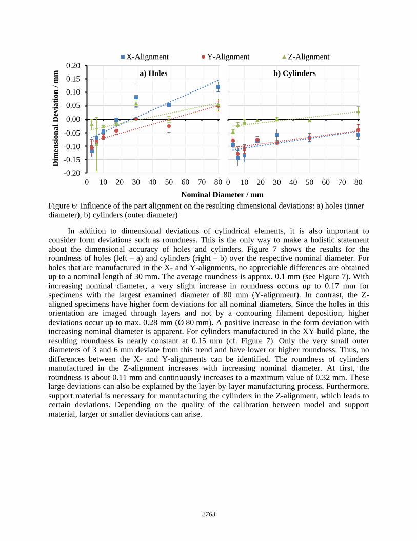
Figure 6: Influence of the part alignment on the resulting dimensional deviations: a) holes (inner diameter), b) cylinders (outer diameter)
In addition to dimensional deviations of cylindrical elements, it is also important to consider form deviations such as roundness. This is the only way to make a holistic statement about the dimensional accuracy of holes and cylinders. Figure 7 shows the results for the roundness of holes (left – a) and cylinders (right – b) over the respective nominal diameter. For holes that are manufactured in the X- and Y-alignments, no appreciable differences are obtained up to a nominal length of 30 mm. The average roundness is approx. 0.1 mm (see Figure 7). With increasing nominal diameter, a very slight increase in roundness occurs up to 0.17 mm for specimens with the largest examined diameter of 80 mm (Y-alignment). In contrast, the Z-aligned specimens have higher form deviations for all nominal diameters. Since the holes in this orientation are imaged through layers and not by a contouring filament deposition, higher deviations occur up to max. 0.28 mm (Ø 80 mm). A positive increase in the form deviation with increasing nominal diameter is apparent. For cylinders manufactured in the XY-build plane, the resulting roundness is nearly constant at 0.15 mm (cf. Figure 7). Only the very small outer diameters of 3 and 6 mm deviate from this trend and have lower or higher roundness. Thus, no differences between the X- and Y-alignments can be identified. The roundness of cylinders manufactured in the Z-alignment increases with increasing nominal diameter. At first, the roundness is about 0.11 mm and continuously increases to a maximum value of 0.32 mm. These large deviations can also be explained by the layer-by-layer manufacturing process. Furthermore, support material is necessary for manufacturing the cylinders in the Z-alignment, which leads to certain deviations. Depending on the quality of the calibration between model and support material, larger or smaller deviations can arise.
-0,20
-0,15
-0,10
-0,05
0,00
0,05
0,10
0,15
0,20
0 10 20 30 40 50 60 70 80
Dim
ensi
onal
Dev
iatio
n / m
m
Nominal Diameter / mm
X-Alignment Y-Alignment Z-Alignment
0 10 20 30 40 50 60 70 80
a) Holes b) Cylinders0.20
0.15
0.10
0.05
0.00
-0.05
-0.10
-0.15
-0.20
2763
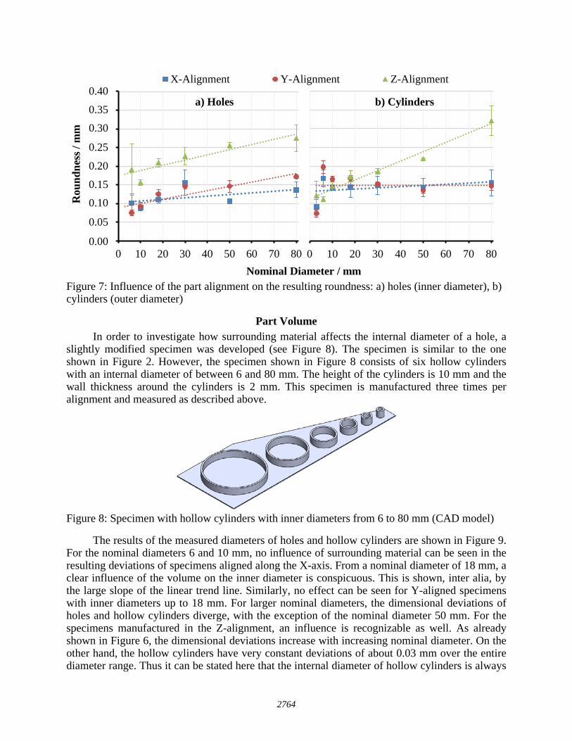
Figure 7: Influence of the part alignment on the resulting roundness: a) holes (inner diameter), b) cylinders (outer diameter)
Part Volume In order to investigate how surrounding material affects the internal diameter of a hole, a
slightly modified specimen was developed (see Figure 8). The specimen is similar to the one shown in Figure 2. However, the specimen shown in Figure 8 consists of six hollow cylinders with an internal diameter of between 6 and 80 mm. The height of the cylinders is 10 mm and the wall thickness around the cylinders is 2 mm. This specimen is manufactured three times per alignment and measured as described above.
Figure 8: Specimen with hollow cylinders with inner diameters from 6 to 80 mm (CAD model)
The results of the measured diameters of holes and hollow cylinders are shown in Figure 9. For the nominal diameters 6 and 10 mm, no influence of surrounding material can be seen in the resulting deviations of specimens aligned along the X-axis. From a nominal diameter of 18 mm, a clear influence of the volume on the inner diameter is conspicuous. This is shown, inter alia, by the large slope of the linear trend line. Similarly, no effect can be seen for Y-aligned specimens with inner diameters up to 18 mm. For larger nominal diameters, the dimensional deviations of holes and hollow cylinders diverge, with the exception of the nominal diameter 50 mm. For the specimens manufactured in the Z-alignment, an influence is recognizable as well. As already shown in Figure 6, the dimensional deviations increase with increasing nominal diameter. On the other hand, the hollow cylinders have very constant deviations of about 0.03 mm over the entire diameter range. Thus it can be stated here that the internal diameter of hollow cylinders is always
0,00
0,05
0,10
0,15
0,20
0,25
0,30
0,35
0,40
0 10 20 30 40 50 60 70 80
Rou
ndne
ss /
mm
Nominal Diameter / mm
X-Alignment Y-Alignment Z-Alignment
0 10 20 30 40 50 60 70 80
a) Holes b) Cylinders0.40
0.35
0.30
0.25
0.20
0.15
0.10
0.05
0.00
2764
much smaller. However, for each nominal length it is necessary to prove independently where better dimensional accuracy exists.
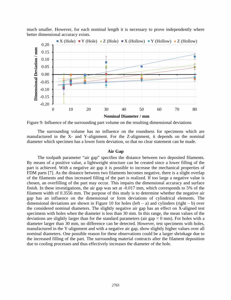
Figure 9: Influence of the surrounding part volume on the resulting dimensional deviations
The surrounding volume has no influence on the roundness for specimens which are manufactured in the X- and Y-alignment. For the Z-alignment, it depends on the nominal diameter which specimen has a lower form deviation, so that no clear statement can be made.
Air Gap The toolpath parameter “air gap” specifies the distance between two deposited filaments.
By means of a positive value, a lightweight structure can be created since a lower filling of the part is achieved. With a negative air gap it is possible to increase the mechanical properties of FDM parts [7]. As the distance between two filaments becomes negative, there is a slight overlap of the filaments and thus increased filling of the part is realized. If too large a negative value is chosen, an overfilling of the part may occur. This impairs the dimensional accuracy and surface finish. In these investigations, the air gap was set at -0.017 mm, which corresponds to 5% of the filament width of 0.3556 mm. The purpose of this study is to determine whether the negative air gap has an influence on the dimensional or form deviations of cylindrical elements. The dimensional deviations are shown in Figure 10 for holes (left – a) and cylinders (right – b) over the considered nominal diameters. The slightly negative air gap has an effect on X-aligned test specimens with holes when the diameter is less than 30 mm. In this range, the mean values of the deviations are slightly larger than for the standard parameters (air gap = 0 mm). For holes with a diameter larger than 30 mm, no difference can be detected. However, test specimens with holes, manufactured in the Y-alignment and with a negative air gap, show slightly higher values over all nominal diameters. One possible reason for these observations could be a larger shrinkage due to the increased filling of the part. The surrounding material contracts after the filament deposition due to cooling processes and thus effectively increases the diameter of the hole.
-0,20
-0,15
-0,10
-0,05
0,00
0,05
0,10
0,15
0,20
0 10 20 30 40 50 60 70 80
Dim
ensi
onal
Dev
iatio
n / m
m
Nominal Diameter / mm
X (Hole) Y (Hole) Z (Hole) X (Hollow) Y (Hollow) Z (Hollow)0.20
0.15
0.10
0.05
0.00
-0.05
-0.10
-0.15
-0.20
2765
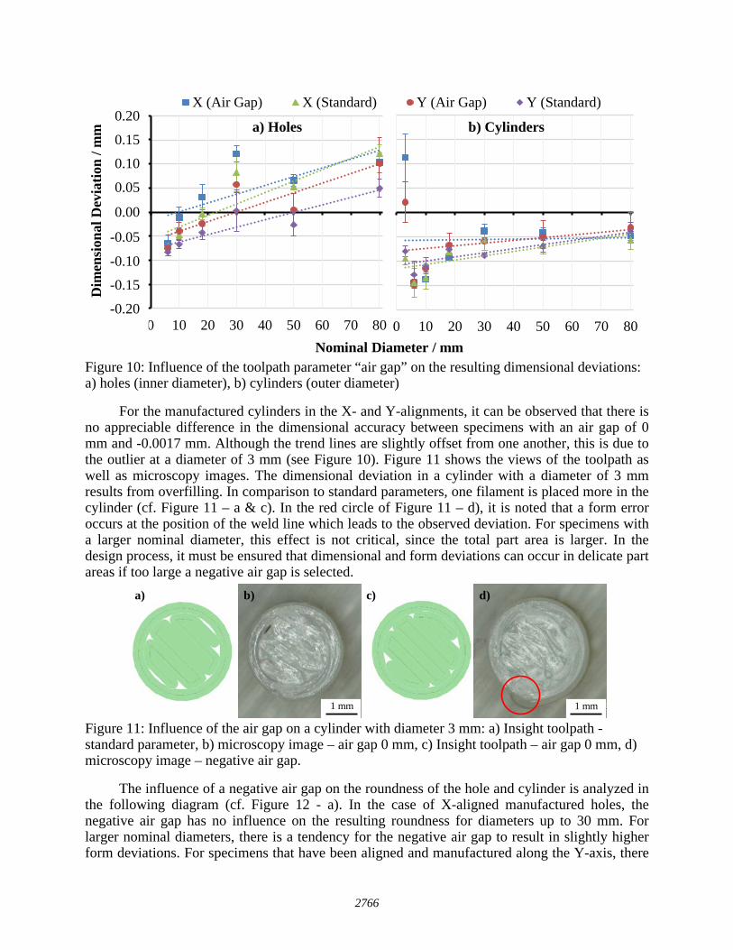
Figure 10: Influence of the toolpath parameter “air gap” on the resulting dimensional deviations: a) holes (inner diameter), b) cylinders (outer diameter)
For the manufactured cylinders in the X- and Y-alignments, it can be observed that there is no appreciable difference in the dimensional accuracy between specimens with an air gap of 0 mm and -0.0017 mm. Although the trend lines are slightly offset from one another, this is due to the outlier at a diameter of 3 mm (see Figure 10). Figure 11 shows the views of the toolpath as well as microscopy images. The dimensional deviation in a cylinder with a diameter of 3 mm results from overfilling. In comparison to standard parameters, one filament is placed more in the cylinder (cf. Figure 11 – a & c). In the red circle of Figure 11 – d), it is noted that a form error occurs at the position of the weld line which leads to the observed deviation. For specimens with a larger nominal diameter, this effect is not critical, since the total part area is larger. In the design process, it must be ensured that dimensional and form deviations can occur in delicate part areas if too large a negative air gap is selected.
Figure 11: Influence of the air gap on a cylinder with diameter 3 mm: a) Insight toolpath - standard parameter, b) microscopy image – air gap 0 mm, c) Insight toolpath – air gap 0 mm, d) microscopy image – negative air gap.
The influence of a negative air gap on the roundness of the hole and cylinder is analyzed in the following diagram (cf. Figure 12 - a). In the case of X-aligned manufactured holes, the negative air gap has no influence on the resulting roundness for diameters up to 30 mm. For larger nominal diameters, there is a tendency for the negative air gap to result in slightly higher form deviations. For specimens that have been aligned and manufactured along the Y-axis, there
-0,20
-0,15
-0,10
-0,05
0,00
0,05
0,10
0,15
0,20
0 10 20 30 40 50 60 70 80
Dim
ensi
onal
Dev
iatio
n / m
m
Nominal Diameter / mm
X (Air Gap) X (Standard) Y (Air Gap) Y (Standard)
0 10 20 30 40 50 60 70 80
a) Holes b) Cylinders0.20
0.15
0.10
0.05
0.00
-0.05
-0.10
-0.15
-0.20
1 mm1 mm
a) b) c) d)
2766
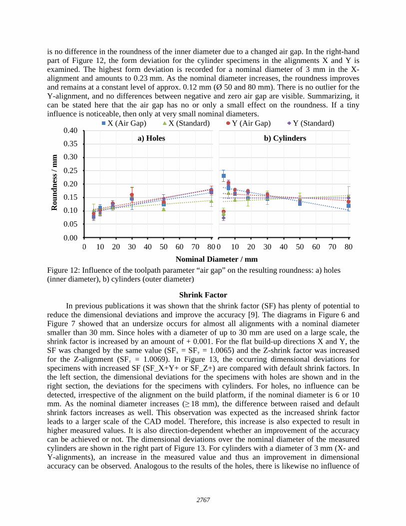
is no difference in the roundness of the inner diameter due to a changed air gap. In the right-hand part of Figure 12, the form deviation for the cylinder specimens in the alignments X and Y is examined. The highest form deviation is recorded for a nominal diameter of 3 mm in the X-alignment and amounts to 0.23 mm. As the nominal diameter increases, the roundness improves and remains at a constant level of approx. 0.12 mm (Ø 50 and 80 mm). There is no outlier for the Y-alignment, and no differences between negative and zero air gap are visible. Summarizing, it can be stated here that the air gap has no or only a small effect on the roundness. If a tiny influence is noticeable, then only at very small nominal diameters.
Figure 12: Influence of the toolpath parameter “air gap” on the resulting roundness: a) holes (inner diameter), b) cylinders (outer diameter)
Shrink Factor In previous publications it was shown that the shrink factor (SF) has plenty of potential to
reduce the dimensional deviations and improve the accuracy [9]. The diagrams in Figure 6 and Figure 7 showed that an undersize occurs for almost all alignments with a nominal diameter smaller than 30 mm. Since holes with a diameter of up to 30 mm are used on a large scale, the shrink factor is increased by an amount of + 0.001. For the flat build-up directions X and Y, the SF was changed by the same value (SFx = SFy = 1.0065) and the Z-shrink factor was increased for the Z-alignment (SFz = 1.0069). In Figure 13, the occurring dimensional deviations for specimens with increased SF (SF_X+Y+ or SF_Z+) are compared with default shrink factors. In the left section, the dimensional deviations for the specimens with holes are shown and in the right section, the deviations for the specimens with cylinders. For holes, no influence can be detected, irrespective of the alignment on the build platform, if the nominal diameter is 6 or 10 mm. As the nominal diameter increases (≥ 18 mm), the difference between raised and default shrink factors increases as well. This observation was expected as the increased shrink factor leads to a larger scale of the CAD model. Therefore, this increase is also expected to result in higher measured values. It is also direction-dependent whether an improvement of the accuracy can be achieved or not. The dimensional deviations over the nominal diameter of the measured cylinders are shown in the right part of Figure 13. For cylinders with a diameter of 3 mm (X- and Y-alignments), an increase in the measured value and thus an improvement in dimensional accuracy can be observed. Analogous to the results of the holes, there is likewise no influence of
0,00
0,05
0,10
0,15
0,20
0,25
0,30
0,35
0,40
0 10 20 30 40 50 60 70 80
Rou
ndne
ss /
mm
Nominal Diameter / mm
X (Air Gap) X (Standard) Y (Air Gap) Y (Standard)
0 10 20 30 40 50 60 70 80
a) Holes b) Cylinders0.40
0.35
0.30
0.25
0.20
0.15
0.10
0.05
0.00
2767
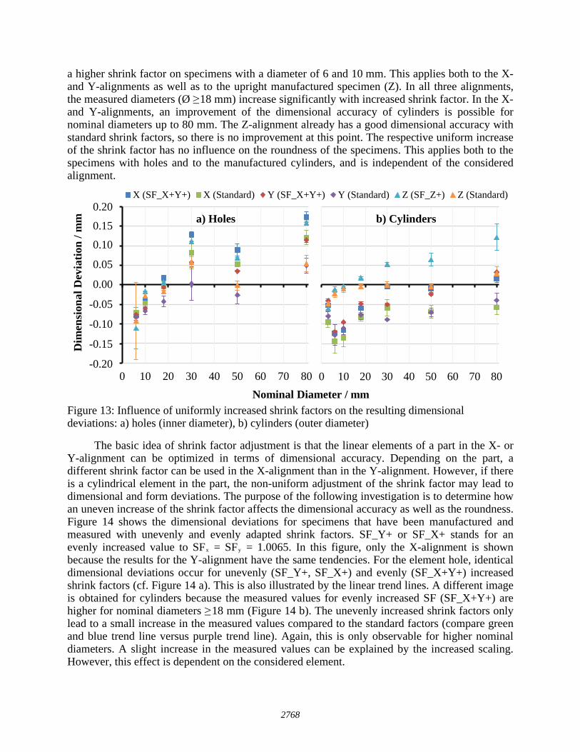
a higher shrink factor on specimens with a diameter of 6 and 10 mm. This applies both to the X- and Y-alignments as well as to the upright manufactured specimen (Z). In all three alignments, the measured diameters (Ø ≥ 18 mm) increase significantly with increased shrink factor. In the X- and Y-alignments, an improvement of the dimensional accuracy of cylinders is possible for nominal diameters up to 80 mm. The Z-alignment already has a good dimensional accuracy with standard shrink factors, so there is no improvement at this point. The respective uniform increase of the shrink factor has no influence on the roundness of the specimens. This applies both to the specimens with holes and to the manufactured cylinders, and is independent of the considered alignment.
Figure 13: Influence of uniformly increased shrink factors on the resulting dimensional deviations: a) holes (inner diameter), b) cylinders (outer diameter)
The basic idea of shrink factor adjustment is that the linear elements of a part in the X- or Y-alignment can be optimized in terms of dimensional accuracy. Depending on the part, a different shrink factor can be used in the X-alignment than in the Y-alignment. However, if there is a cylindrical element in the part, the non-uniform adjustment of the shrink factor may lead to dimensional and form deviations. The purpose of the following investigation is to determine how an uneven increase of the shrink factor affects the dimensional accuracy as well as the roundness. Figure 14 shows the dimensional deviations for specimens that have been manufactured and measured with unevenly and evenly adapted shrink factors. SF_Y+ or SF_X+ stands for an evenly increased value to SFx = SFy = 1.0065. In this figure, only the X-alignment is shown because the results for the Y-alignment have the same tendencies. For the element hole, identical dimensional deviations occur for unevenly (SF_Y+, SF_X+) and evenly (SF_X+Y+) increased shrink factors (cf. Figure 14 a). This is also illustrated by the linear trend lines. A different image is obtained for cylinders because the measured values for evenly increased SF (SF_X+Y+) are higher for nominal diameters ≥ 18 mm (Figure 14 b). The unevenly increased shrink factors only lead to a small increase in the measured values compared to the standard factors (compare green and blue trend line versus purple trend line). Again, this is only observable for higher nominal diameters. A slight increase in the measured values can be explained by the increased scaling. However, this effect is dependent on the considered element.
-0,20
-0,15
-0,10
-0,05
0,00
0,05
0,10
0,15
0,20
0 10 20 30 40 50 60 70 80
Dim
ensi
onal
Dev
iatio
n / m
m
Nominal Diameter / mm
X (SF_X+Y+) X (Standard) Y (SF_X+Y+) Y (Standard) Z (SF_Z+) Z (Standard)
0 10 20 30 40 50 60 70 80
a) Holes b) Cylinders0.20
0.15
0.10
0.05
0.00
-0.05
-0.10
-0.15
-0.20
2768
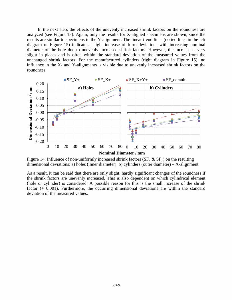
In the next step, the effects of the unevenly increased shrink factors on the roundness are analyzed (see Figure 15). Again, only the results for X-aligned specimens are shown, since the results are similar to specimens in the Y-alignment. The linear trend lines (dotted lines in the left diagram of Figure 15) indicate a slight increase of form deviations with increasing nominal diameter of the hole due to unevenly increased shrink factors. However, the increase is very slight in places and is often within the standard deviation of the measured values from the unchanged shrink factors. For the manufactured cylinders (right diagram in Figure 15), no influence in the X- and Y-alignments is visible due to unevenly increased shrink factors on the roundness.
Figure 14: Influence of non-uniformly increased shrink factors (SFx & SFy) on the resulting dimensional deviations: a) holes (inner diameter), b) cylinders (outer diameter) – X-alignment
As a result, it can be said that there are only slight, hardly significant changes of the roundness if the shrink factors are unevenly increased. This is also dependent on which cylindrical element (hole or cylinder) is considered. A possible reason for this is the small increase of the shrink factor (+ 0.001). Furthermore, the occurring dimensional deviations are within the standard deviation of the measured values.
-0,20-0,15-0,10-0,050,000,050,100,150,20
0 10 20 30 40 50 60 70 80
Dim
ensi
onal
Dev
iatio
n / m
m
Nominal Diameter / mm
SF_Y+ SF_X+ SF_X+Y+ SF_default
0 10 20 30 40 50 60 70 80
a) Holes b) Cylinders0.20
0.150.100.050.00
-0.05
-0.10-0.15-0.20
2769
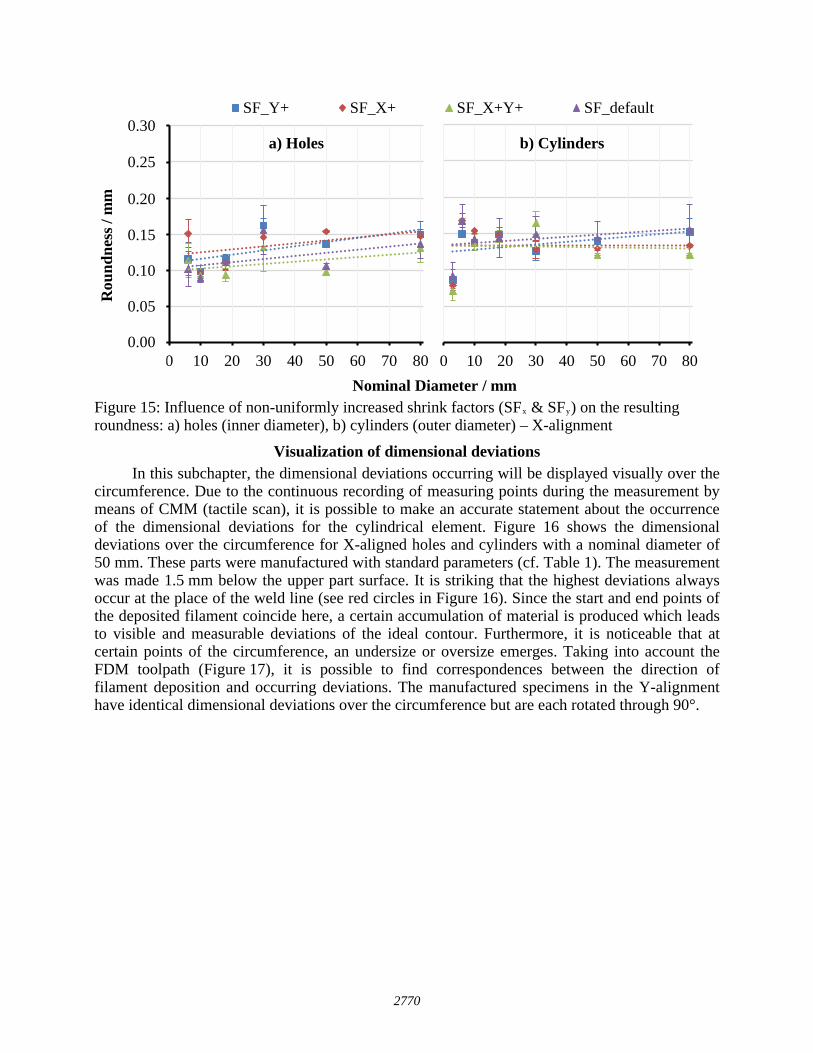
Figure 15: Influence of non-uniformly increased shrink factors (SFx & SFy) on the resulting roundness: a) holes (inner diameter), b) cylinders (outer diameter) – X-alignment
Visualization of dimensional deviations In this subchapter, the dimensional deviations occurring will be displayed visually over the
circumference. Due to the continuous recording of measuring points during the measurement by means of CMM (tactile scan), it is possible to make an accurate statement about the occurrence of the dimensional deviations for the cylindrical element. Figure 16 shows the dimensional deviations over the circumference for X-aligned holes and cylinders with a nominal diameter of 50 mm. These parts were manufactured with standard parameters (cf. Table 1). The measurement was made 1.5 mm below the upper part surface. It is striking that the highest deviations always occur at the place of the weld line (see red circles in Figure 16). Since the start and end points of the deposited filament coincide here, a certain accumulation of material is produced which leads to visible and measurable deviations of the ideal contour. Furthermore, it is noticeable that at certain points of the circumference, an undersize or oversize emerges. Taking into account the FDM toolpath (Figure 17), it is possible to find correspondences between the direction of filament deposition and occurring deviations. The manufactured specimens in the Y-alignment have identical dimensional deviations over the circumference but are each rotated through 90°.
0,00
0,05
0,10
0,15
0,20
0,25
0,30
0 10 20 30 40 50 60 70 80
Rou
ndne
ss /
mm
Nominal Diameter / mm
SF_Y+ SF_X+ SF_X+Y+ SF_default
0 10 20 30 40 50 60 70 80
0.30
0.25
0.20
0.15
0.10
0.05
0.00
a) Holes b) Cylinders
2770
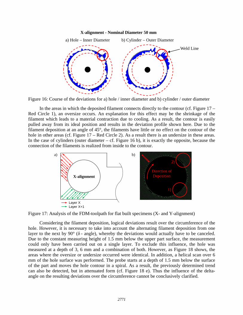
Figure 16: Course of the deviations for a) hole / inner diameter and b) cylinder / outer diameter
In the areas in which the deposited filament connects directly to the contour (cf. Figure 17 – Red Circle 1), an oversize occurs. An explanation for this effect may be the shrinkage of the filament which leads to a material contraction due to cooling. As a result, the contour is easily pulled away from its ideal position and results in the deviation profile shown here. Due to the filament deposition at an angle of 45°, the filaments have little or no effect on the contour of the hole in other areas (cf. Figure 17 – Red Circle 2). As a result there is an undersize in these areas. In the case of cylinders (outer diameter – cf. Figure 16 b), it is exactly the opposite, because the connection of the filaments is realized from inside to the contour.
Figure 17: Analysis of the FDM-toolpath for flat built specimens (X- and Y-alignment)
Considering the filament deposition, logical deviations result over the circumference of the hole. However, it is necessary to take into account the alternating filament deposition from one layer to the next by 90° (δ - angle), whereby the deviations would actually have to be canceled. Due to the constant measuring height of 1.5 mm below the upper part surface, the measurement could only have been carried out on a single layer. To exclude this influence, the hole was measured at a depth of 3, 6 mm and a combination of both. However, as Figure 18 shows, the areas where the oversize or undersize occurred were identical. In addition, a helical scan over 6 mm of the hole surface was performed. The probe starts at a depth of 1.5 mm below the surface of the part and moves the hole contour in a spiral. As a result, the previously determined trend can also be detected, but in attenuated form (cf. Figure 18 e). Thus the influence of the delta-angle on the resulting deviations over the circumference cannot be conclusively clarified.
a) Hole – Inner Diameter b) Cylinder – Outer Diameter
X-alignment - Nominal Diameter 50 mm
Weld Line
X-alignment
Layer XLayer X+1
a)
Direction of Deposition
b)
1)
2)
2771
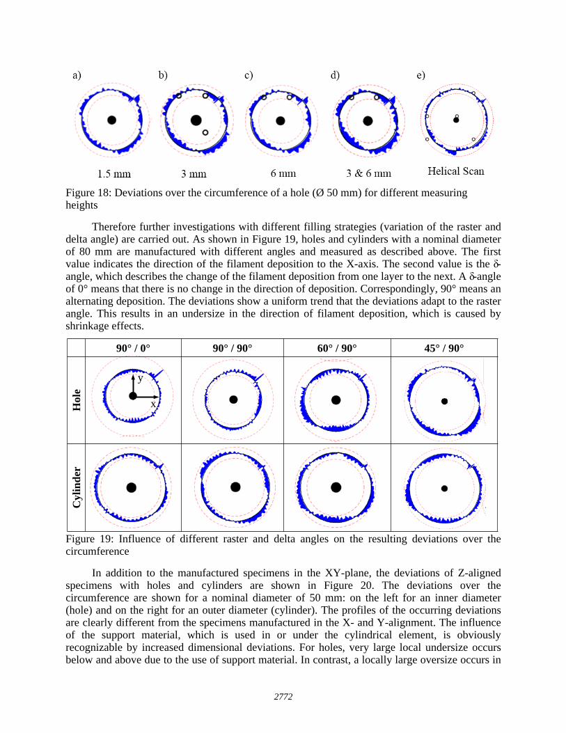
Figure 18: Deviations over the circumference of a hole (Ø 50 mm) for different measuring heights
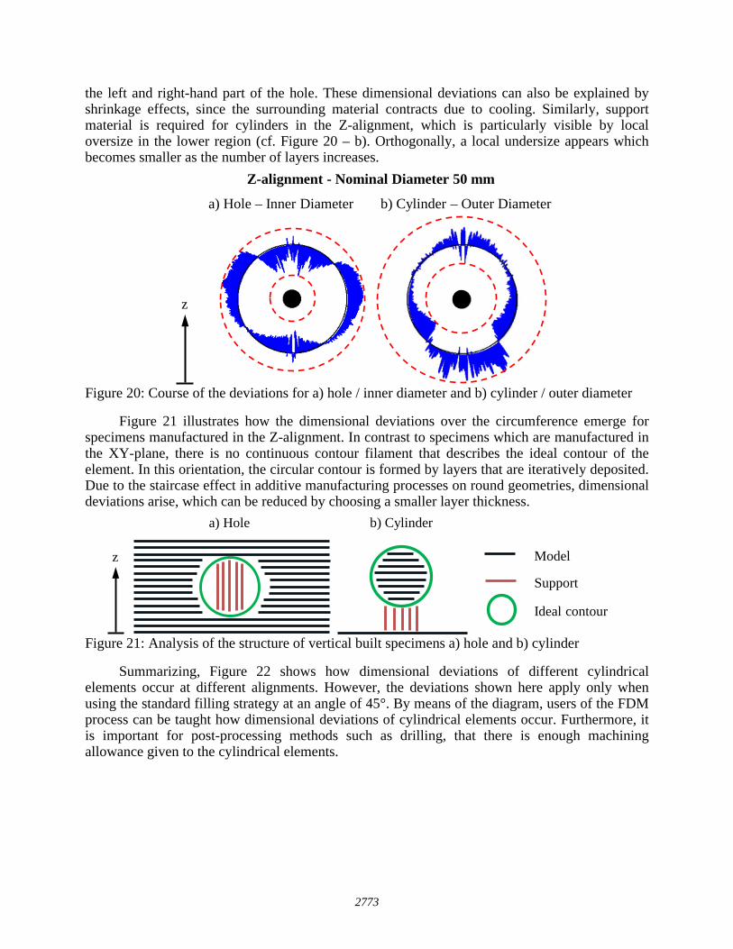
Therefore further investigations with different filling strategies (variation of the raster and delta angle) are carried out. As shown in Figure 19, holes and cylinders with a nominal diameter of 80 mm are manufactured with different angles and measured as described above. The first value indicates the direction of the filament deposition to the X-axis. The second value is the δ-angle, which describes the change of the filament deposition from one layer to the next. A δ-angle of 0° means that there is no change in the direction of deposition. Correspondingly, 90° means an alternating deposition. The deviations show a uniform trend that the deviations adapt to the raster angle. This results in an undersize in the direction of filament deposition, which is caused by shrinkage effects.
Figure 19: Influence of different raster and delta angles on the resulting deviations over the circumference
In addition to the manufactured specimens in the XY-plane, the deviations of Z-aligned specimens with holes and cylinders are shown in Figure 20. The deviations over the circumference are shown for a nominal diameter of 50 mm: on the left for an inner diameter (hole) and on the right for an outer diameter (cylinder). The profiles of the occurring deviations are clearly different from the specimens manufactured in the X- and Y-alignment. The influence of the support material, which is used in or under the cylindrical element, is obviously recognizable by increased dimensional deviations. For holes, very large local undersize occurs below and above due to the use of support material. In contrast, a locally large oversize occurs in
y
x
90° / 0° 90° / 90° 60° / 90° 45° / 90°
Hol
eC
ylin
der
2772
the left and right-hand part of the hole. These dimensional deviations can also be explained by shrinkage effects, since the surrounding material contracts due to cooling. Similarly, support material is required for cylinders in the Z-alignment, which is particularly visible by local oversize in the lower region (cf. Figure 20 – b). Orthogonally, a local undersize appears which becomes smaller as the number of layers increases.
Figure 20: Course of the deviations for a) hole / inner diameter and b) cylinder / outer diameter
Figure 21 illustrates how the dimensional deviations over the circumference emerge for specimens manufactured in the Z-alignment. In contrast to specimens which are manufactured in the XY-plane, there is no continuous contour filament that describes the ideal contour of the element. In this orientation, the circular contour is formed by layers that are iteratively deposited. Due to the staircase effect in additive manufacturing processes on round geometries, dimensional deviations arise, which can be reduced by choosing a smaller layer thickness.
Figure 21: Analysis of the structure of vertical built specimens a) hole and b) cylinder
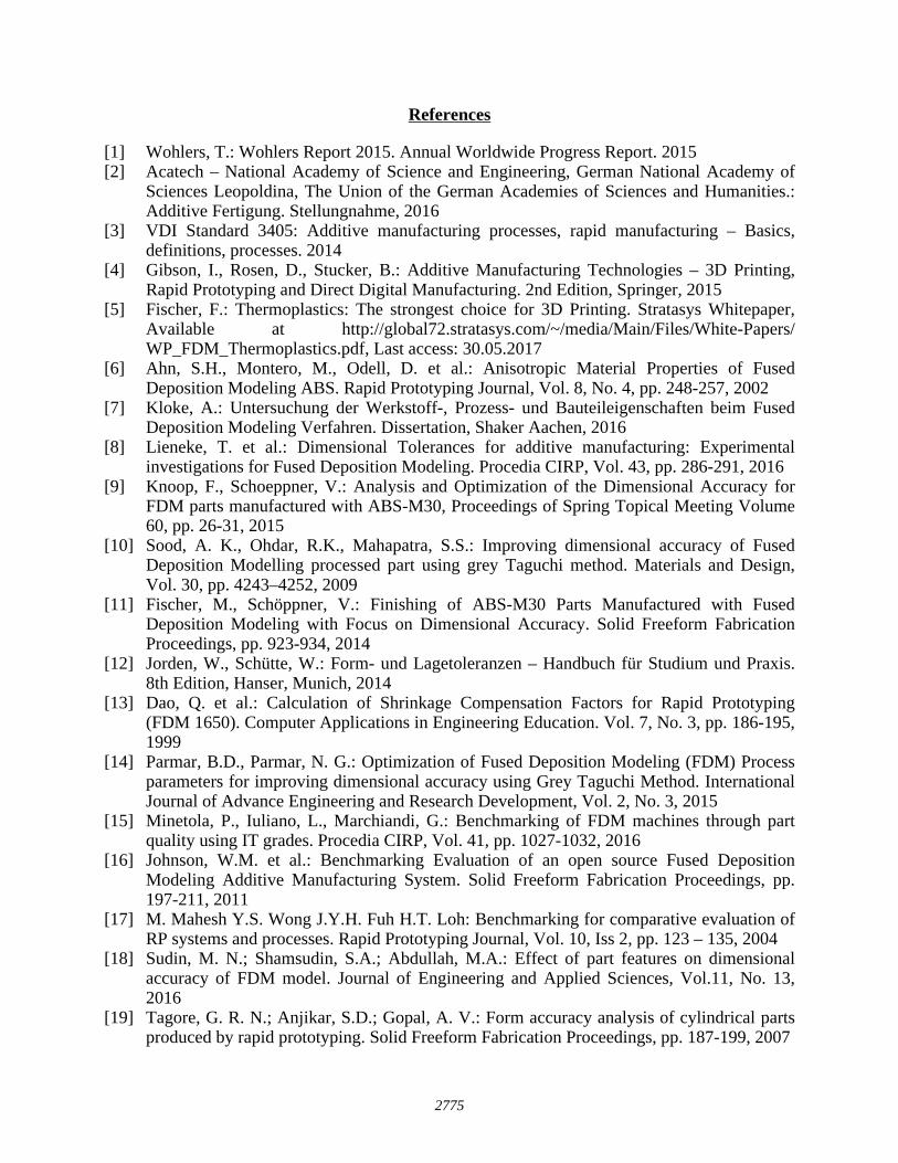
Summarizing, Figure 22 shows how dimensional deviations of different cylindrical elements occur at different alignments. However, the deviations shown here apply only when using the standard filling strategy at an angle of 45°. By means of the diagram, users of the FDM process can be taught how dimensional deviations of cylindrical elements occur. Furthermore, it is important for post-processing methods such as drilling, that there is enough machining allowance given to the cylindrical elements.
a) Hole – Inner Diameter b) Cylinder – Outer Diameter
Z-alignment - Nominal Diameter 50 mm
z
Ideal contour
Support
Model
a) Hole b) Cylinder
z
2773
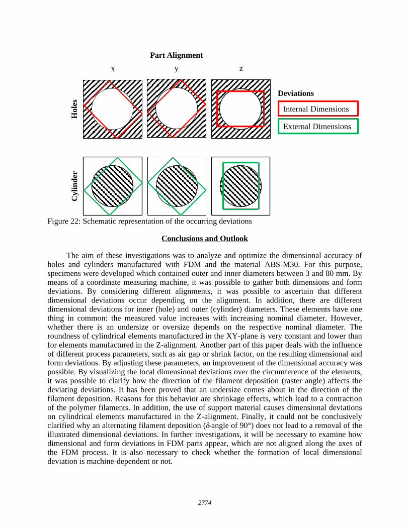
Figure 22: Schematic representation of the occurring deviations
Conclusions and Outlook
The aim of these investigations was to analyze and optimize the dimensional accuracy of holes and cylinders manufactured with FDM and the material ABS-M30. For this purpose, specimens were developed which contained outer and inner diameters between 3 and 80 mm. By means of a coordinate measuring machine, it was possible to gather both dimensions and form deviations. By considering different alignments, it was possible to ascertain that different dimensional deviations occur depending on the alignment. In addition, there are different dimensional deviations for inner (hole) and outer (cylinder) diameters. These elements have one thing in common: the measured value increases with increasing nominal diameter. However, whether there is an undersize or oversize depends on the respective nominal diameter. The roundness of cylindrical elements manufactured in the XY-plane is very constant and lower than for elements manufactured in the Z-alignment. Another part of this paper deals with the influence of different process parameters, such as air gap or shrink factor, on the resulting dimensional and form deviations. By adjusting these parameters, an improvement of the dimensional accuracy was possible. By visualizing the local dimensional deviations over the circumference of the elements, it was possible to clarify how the direction of the filament deposition (raster angle) affects the deviating deviations. It has been proved that an undersize comes about in the direction of the filament deposition. Reasons for this behavior are shrinkage effects, which lead to a contraction of the polymer filaments. In addition, the use of support material causes dimensional deviations on cylindrical elements manufactured in the Z-alignment. Finally, it could not be conclusively clarified why an alternating filament deposition (δ-angle of 90°) does not lead to a removal of the illustrated dimensional deviations. In further investigations, it will be necessary to examine how dimensional and form deviations in FDM parts appear, which are not aligned along the axes of the FDM process. It is also necessary to check whether the formation of local dimensional deviation is machine-dependent or not.
Hol
esC
ylin
der
x y z
Part Alignment
Internal Dimensions
External Dimensions
Deviations
2774
References
[1] Wohlers, T.: Wohlers Report 2015. Annual Worldwide Progress Report. 2015 [2] Acatech – National Academy of Science and Engineering, German National Academy of
Sciences Leopoldina, The Union of the German Academies of Sciences and Humanities.: Additive Fertigung. Stellungnahme, 2016
[3] VDI Standard 3405: Additive manufacturing processes, rapid manufacturing – Basics, definitions, processes. 2014
[4] Gibson, I., Rosen, D., Stucker, B.: Additive Manufacturing Technologies – 3D Printing, Rapid Prototyping and Direct Digital Manufacturing. 2nd Edition, Springer, 2015
[5] Fischer, F.: Thermoplastics: The strongest choice for 3D Printing. Stratasys Whitepaper, Available at http://global72.stratasys.com/~/media/Main/Files/White-Papers/ WP_FDM_Thermoplastics.pdf, Last access: 30.05.2017
[6] Ahn, S.H., Montero, M., Odell, D. et al.: Anisotropic Material Properties of Fused Deposition Modeling ABS. Rapid Prototyping Journal, Vol. 8, No. 4, pp. 248-257, 2002
[7] Kloke, A.: Untersuchung der Werkstoff-, Prozess- und Bauteileigenschaften beim Fused Deposition Modeling Verfahren. Dissertation, Shaker Aachen, 2016
[8] Lieneke, T. et al.: Dimensional Tolerances for additive manufacturing: Experimental investigations for Fused Deposition Modeling. Procedia CIRP, Vol. 43, pp. 286-291, 2016
[9] Knoop, F., Schoeppner, V.: Analysis and Optimization of the Dimensional Accuracy for FDM parts manufactured with ABS-M30, Proceedings of Spring Topical Meeting Volume 60, pp. 26-31, 2015
[10] Sood, A. K., Ohdar, R.K., Mahapatra, S.S.: Improving dimensional accuracy of Fused Deposition Modelling processed part using grey Taguchi method. Materials and Design, Vol. 30, pp. 4243–4252, 2009
[11] Fischer, M., Schöppner, V.: Finishing of ABS-M30 Parts Manufactured with Fused Deposition Modeling with Focus on Dimensional Accuracy. Solid Freeform Fabrication Proceedings, pp. 923-934, 2014
[12] Jorden, W., Schütte, W.: Form- und Lagetoleranzen – Handbuch für Studium und Praxis. 8th Edition, Hanser, Munich, 2014
[13] Dao, Q. et al.: Calculation of Shrinkage Compensation Factors for Rapid Prototyping (FDM 1650). Computer Applications in Engineering Education. Vol. 7, No. 3, pp. 186-195, 1999
[14] Parmar, B.D., Parmar, N. G.: Optimization of Fused Deposition Modeling (FDM) Process parameters for improving dimensional accuracy using Grey Taguchi Method. International Journal of Advance Engineering and Research Development, Vol. 2, No. 3, 2015
[15] Minetola, P., Iuliano, L., Marchiandi, G.: Benchmarking of FDM machines through part quality using IT grades. Procedia CIRP, Vol. 41, pp. 1027-1032, 2016
[16] Johnson, W.M. et al.: Benchmarking Evaluation of an open source Fused Deposition Modeling Additive Manufacturing System. Solid Freeform Fabrication Proceedings, pp. 197-211, 2011
[17] M. Mahesh Y.S. Wong J.Y.H. Fuh H.T. Loh: Benchmarking for comparative evaluation of RP systems and processes. Rapid Prototyping Journal, Vol. 10, Iss 2, pp. 123 – 135, 2004
[18] Sudin, M. N.; Shamsudin, S.A.; Abdullah, M.A.: Effect of part features on dimensional accuracy of FDM model. Journal of Engineering and Applied Sciences, Vol.11, No. 13, 2016
[19] Tagore, G. R. N.; Anjikar, S.D.; Gopal, A. V.: Form accuracy analysis of cylindrical parts produced by rapid prototyping. Solid Freeform Fabrication Proceedings, pp. 187-199, 2007
2775
[20] Bakar, N. S. A., Alkahari, M. R., Boejang, H.: Analysis on fused deposition modelling performance, Journal of Zhejiang University-SCIENCE A - Applied Physics & Engineering, Vol. 11, Issue 12, pp. 972-977, 2010
[21] Stratasys: Material Safety Sheet ABS-M30 (Revision: 07.01.2013). http://www.formias.si/documents/MSDS%20EU%20P430%20English.pdf, Last access: 31.05.2017
[22] Domininghaus, H. et al.: Kunststoffe – Eigenschaften und Anwendungen, 8th Edition, Springer, 2012
[23] Roggensack, J., Beck, C.: Der Mess- und Prüfmittelbeauftragte. WEKA Media GmbH & Co. KG, 2005
[24] German Standard DIN EN ISO 12181-1: „ Geometrical product specifications (GPS) – Roundness – Part 1: Vocabulary and parameters of roundness”, 2011
2776