Geometric Tolerancing - Definitions
23
Geometric Tolerancing - Definitions • Maximum Material Condition (MMC) – The condition in which a feature of size contains the maximum amount of material with the stated limits of size, - fore example, minimum hole diameter and maximum shaft diameter • Least Material Condition (LMC) – Opposite of MMC, the feature contains the least material. For example, maximum hole diameter and minimum shaft diameter • Virtual Condition – The envelope or boundary that describes the collective effects of all tolerance requirements on a feature (See Figure 7-25 TG)
-
Upload
sergio-boillos -
Category
Documents
-
view
294 -
download
2
Transcript of Geometric Tolerancing - Definitions

Geometric Tolerancing - Definitions
• Maximum Material Condition (MMC) – The condition in which a feature of size contains the maximum amount of material with the stated limits of size, - fore example, minimum hole diameter and maximum shaft diameter
• Least Material Condition (LMC) – Opposite of MMC, the feature contains the least material. For example, maximum hole diameter and minimum shaft diameter
• Virtual Condition – The envelope or boundary that describes the collective effects of all tolerance requirements on a feature (See Figure 7-25 TG)
Virtual Condition Envelope All Required Tolerances
20.06 MaximumEnvelope
20.00MaximumAllowable Diameter
0.06MaximumAllowable Curvature

Feature Control Frame
This feature must be parallel to Datum B within .007 at MMC (largest cylinder) as measured on the diameter
.007 M B
Geometric Characteristic Symbol
Tolerance
Material condition
Datum Reference
B.007

Tolerance of Form - Straightness
19.8919.76
0.03
0.03 Tolerance Zone
This cylinder must be straight within 0.03 mm.
What it means -

Concentricity Tolerance Note
XX
A
YY
.007 A
This cylinder (the right cylinder) must be concentric within .007 with the Datum A (the left cylinder) as measured on the diameter
.007 Tolerance Zone
What It Means

DIMENSIONING
Requirements1. Unambiguous2. Completeness3. No redundancy
0.83 ' 0.95 ' 1.22 '
3.03 '
Redundant dimensioning
0.83 ' 1.22 '
3.03 '
1.72 '
0.86 '
Adequate dimensioning
Incompletedimensioning

TOLERANCE
unilateral
bilateral
1.00 0.05+-
nominal dimension
tolerance
0.95 + 0.10- 0.00 1.05 + 0.00
- 0.10
1.00 0.05+-
0.95 - 1.05means a range

"TOLERANCE IS ALWAYS ADDITIVE"
What is the expected dimension and tolerances?
d = 0.80 +1.00 + 1.20 = 3.00
t = ± (0.01 + 0.01 + 0.01) = ± 0.03
0.80 ' ±0.01 1.20 ' ±0.01 1.00 ' ±0.01
?

Maximum x length = 3.01 - 0.79 - 1.19 = 1.03Minimum x length = 2.99 - 0.81 - 1.21 = 0.97
Therefore x = 1.00 ± 0.03
0.80 ' ±0.01 1.20 ' ±0.01
3.00 ' ±0.01
?x
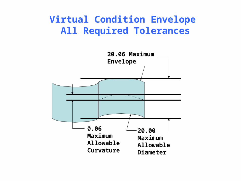
SURFACE FINISH
waviness width
roughness width
waviness
roughness

STRAIGHTNESS
Value must be smaller than the size tolerance.
1.000 ' ±0.002
0.001
Measured error Š 0.001
1.000 ' ±0.002
0.001
0.001
Design Meaning
Tolerance zone between two straightness lines.

FLATNESS
1.000 ' ±0.002
0.001
0.001
parallelplanes
Tolerance zone defined by two parallel planes.

CIRCULARITY (ROUNDNESS)
1.00 ' ±0.05
0.01
0.01 Tolerance zone
At any section along the cylinder
Tolerance zone bounded by two concentric circles.

CYLINDRICITY
1.00 ' ±0.05
0.01
0.01
Rotate in a V
Rotate between points
Tolerance zone bounded by two concentric cylinders within which the cylinder must lie.

PERPENDICULARITYA surface, median plane, or axis at a right angle to the datum planeor axis.
0.500 ' ±0.005 1.000 ' ±0.005
.002 A
2.000 ' ±0.005A
0.002tolerancezone perpendicularto the datum plane
.002 T A
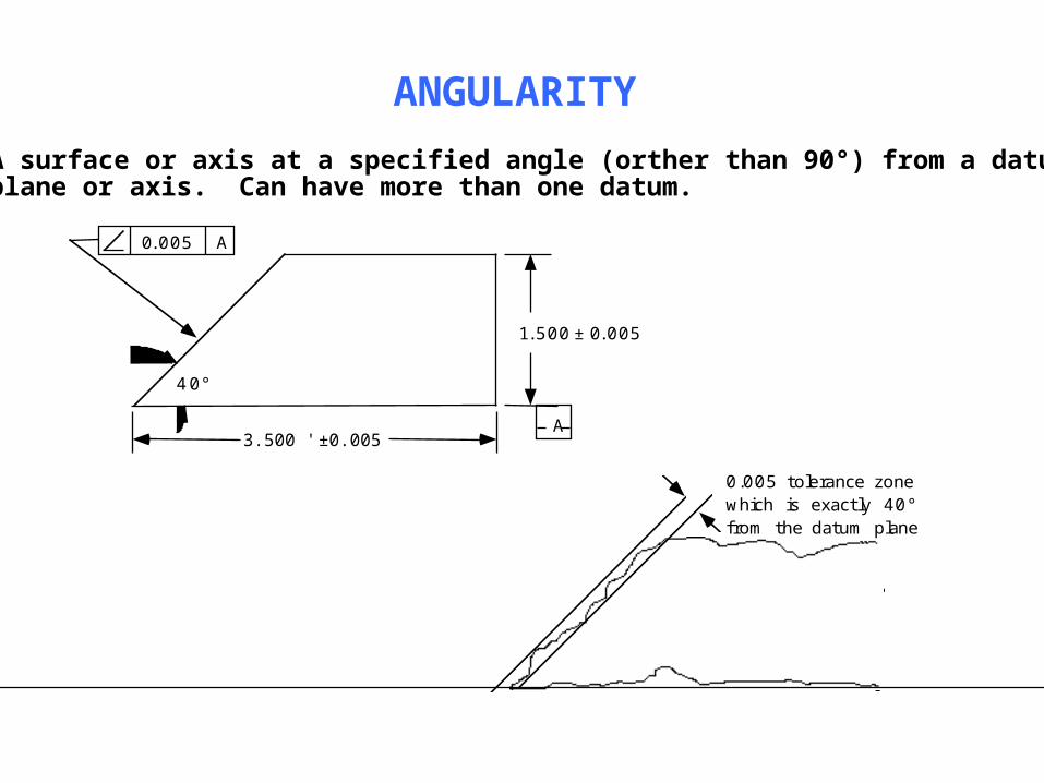
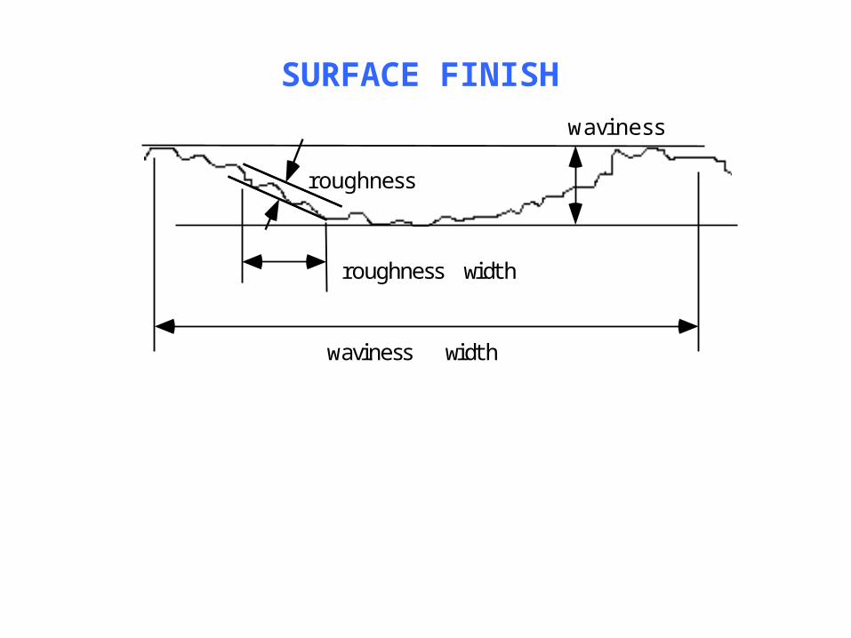
ANGULARITYA surface or axis at a specified angle (orther than 90°) from a datumplane or axis. Can have more than one datum.
0.005 tolerance zonewhich is exactly 40°from the datum plane
3.500 ' ±0.005
1.500 ± 0.005
40°
0.005 A
A

PARALLELISM
1.000 " ±0.005
2.000 " ±0.005
.001 A
A
The condition of a surface equidistant at all points from a datum plane, or an axis equidistant along its length to a datum axis.
0.001

PROFILEA uniform boundary along the true profile within whcih the elements of the surface must lie.
A
B
0.005 A B
0.001
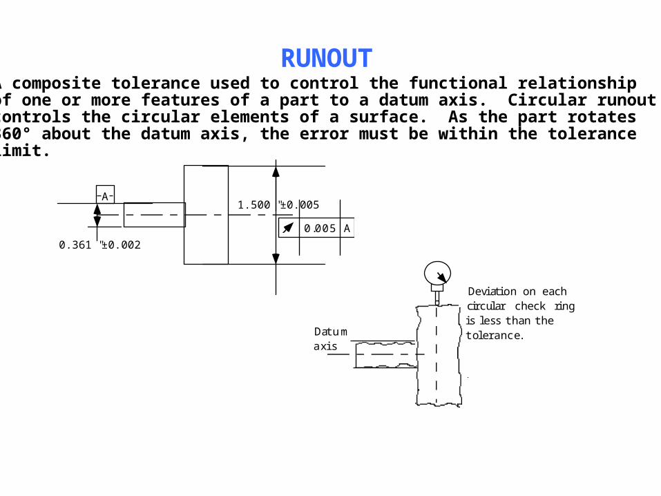
RUNOUT
0.361 " ±0.002
1.500 " ±0.005A
0.005 A
A composite tolerance used to control the functional relationshipof one or more features of a part to a datum axis. Circular runoutcontrols the circular elements of a surface. As the part rotates360° about the datum axis, the error must be within the tolerancelimit.
Datumaxis
Deviation on eachcircular check ringis less than thetolerance.

TOTAL RUNOUT
Datumaxis
Deviation on thetotal swept whenthe part is rotatingis less than thetolerance.
0.361 " ±0.002
1.500 " ±0.005A
0.005 A

TRUE POSITION
1.20± 0.01
1.00 ± 0.01
1.20
1.00
Tolerance zone0.01dia
O 0.01 M A BO .80 ± 0.02
Dimensionaltolerance
True positiontolerance
Hole center tolerance zone
AB
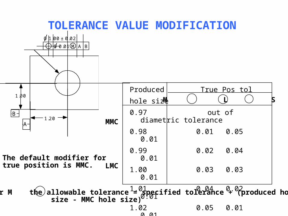
TOLERANCE VALUE MODIFICATION
Produced True Pos tolhole size0.97 out of diametric tolerance0.98 0.01 0.05 0.010.99 0.02 0.04 0.011.00 0.03 0.03 0.011.01 0.04 0.02 0.011.02 0.05 0.01 0.011.03 out of diametric tolerance
1.20
1.00
O 0.01 M A BO 1.00 ± 0.02
M L S
The default modifier for true position is MMC.
MMC
LMC
For M the allowable tolerance = specified tolerance + (produced hole size - MMC hole size)
A
B

MMC HOLE
Given the same peg (MMC peg), when the produced hole size is greater than the MMC hole, the hole axis true position tolerance zone can be enlarged by the amount of difference between the produced hole size and the MMC hole size.
hole axis tolerance zone
MMC holeLMC hole
MMC peg will fit in the holeaxis must be in the tolerance zone
,