GEOMEDIA RESEARCH & DEVELOPMENT Portable … Manual 2.pdf · i PORTABLE SEISMIC PROPERTIES ANALYZER...
85
0 GEOMEDIA RESEARCH & DEVELOPMENT Portable Seismic Properties Analyzer PSPA & SPA Manager Manual Version 2.1e
Transcript of GEOMEDIA RESEARCH & DEVELOPMENT Portable … Manual 2.pdf · i PORTABLE SEISMIC PROPERTIES ANALYZER...

0
GEOMEDIA RESEARCH & DEVELOPMENT
Portable Seismic Properties Analyzer
PSPA & SPA Manager Manual
Version
2.1e

i
P O R T A B L E S E I S M I C P R O P E R T I E S A N A L Y Z E R
PSPA & SPA Manager Manual
Geomedia Research & Development 2007 6040 Strahan Rd.
El Paso, TX 79932 USA
Phone or Fax: ( 915 ) 877 - 2777

Table of Contents
Chapter 1: Overview 1
The PSPA
How the PSPA and SPA
Manager work
SPA vibrations
SPA Measurements
Ultrasonic Surface Wave Method
Impact Echo Method
Comparing SPA to Other
Methods
Reporting SPA Results
Chapter 2: Start SPA 13
Changing Sensor Spacings
Connecting the PSPA
Deploying the PSPA
Starting the SPA Manager
Chapter 3: SPA Options 25
SPA Start Options
SPA Setup Options
SPA Instrument Options
SPA Properties Options
Chapter 4: SPA Projects & Sites 35
Selecting an Application
New Project or Old Site
Name a New Project
Details of a New Project
Chapter 5: SPA Stations 49
Introduction
Creating a New Station
Collecting New Waveforms
Accepting or Rejecting
Waveforms
Reducing SPA Waveforms
Reporting SPA Information
Selecting a Report Format
Chapter 6: PSPA Maintenance 71
Battery Options
PSPA Maintenance
SPA Manager Software
Installation
Index 80
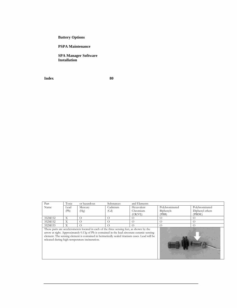
Part Toxic or hazardous Substances and Elements
Name Lead (Pb)
Mercury (Hg)
Cadmium (Cd)
Hexavalent Chromium (CR(VI))
Polybrominated Biphenyls (PBB)
Polybrominated Diphenyl ethers (PBDE)
352M152 X O O O O O
352M152 X O O O O O
352M153 X O O O O O
These parts are accelerometers located in each of the three sensing feet, as shown by the arrow at right. Approximately 0.13g of Pb is contained in the lead zirconate ceramic sensing element. The sensing element is contained in hermetically sealed titanium cases. Lead will be released during high-temperature incineration.

P S P A & S P A M A N A G E R O V E R V I E W
1
SPA Overview
Using the PSPA hardware and the SPA Manager software for nondestructive testing.
he Seismic Property Analyzer or SPA is a field-deployable device for measuring sonic, ultrasonic, and resonant vibrations to nondestructively evaluate concrete pavements and structures, asphalt pavements, as well as base and prepared subgrade materials. The SPA makes high quality stress wave
measurements in an automated fashion without surface preparation, and can perform automated interpretation of results.
The PSPA Hardware
The PSPA hardware consists of a "source", two "receivers" and an electronics box packaged as a hand portable unit. The
hardware is controlled by software (the SPA Manager) running on a computer. A tether (the black USB cable in the picture below) carries command signals generated by the SPA Manager software from the computer to the electronics box. The tether also returns measured signals from the electronics box to the computer.
The SPA Manager software provides a general user interface for acquiring and interpreting seismic waveforms used in nondestructive testing of concrete pavements and structures, asphalt pavements, as well as base and prepared subgrade materials.
The SPA Manager serves as a controller for data acquisition software, waveform reduction software, analysis software (when available) and reporting software. To store field data the SPA Manager creates a directory structure on the computer's hard disk, as well as a structure for project and site information to provide an audit trail that simplifies project documentation.
The waveforms collected with the PSPA hardware can be analyzed using signal processing to determine the seismic modulus and thickness of the materials being evaluated. The analysis can be conducted by either inspecting the recorded signals in
Chapter
1
T
I C O N K E Y
Extra information
Definition
P S P A & S P A M A N A G E R O V E R V I E W
2
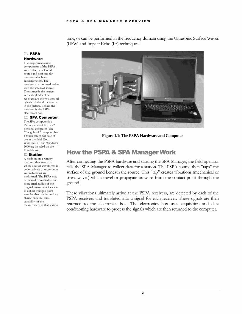
time, or can be performed in the frequency domain using the Ultrasonic Surface Waves (USW) and Impact Echo (IE) techniques.
Figure 1.1: The PSPA Hardware and Computer
How the PSPA & SPA Manager Work
After connecting the PSPA hardware and starting the SPA Manager, the field operator tells the SPA Manager to collect data for a station. The PSPA source then "taps" the surface of the ground beneath the source. This "tap" creates vibrations (mechanical or stress waves) which travel or propagate outward from the contact point through the ground.
These vibrations ultimately arrive at the PSPA receivers, are detected by each of the PSPA receivers and translated into a signal for each receiver. These signals are then returned to the electronics box. The electronics box uses acquisition and data conditioning hardware to process the signals which are then returned to the computer.
PSPA
Hardware
The major mechanical components of the PSPA are an electric solenoid source and near and far receivers which are accelerometers. The receivers are mounted in-line with the solenoid source. The source is the nearest vertical cylinder. The receivers are the two vertical cylinders behind the source in the picture. Behind the receivers is the PSPA electronics box.
SPA Computer
The SPA computer is a Panasonic model CF - 72 personal computer. The "Toughbook" computer has a touch screen for ease of use in the field. Both Windows XP and Windows 2000 are installed on the Toughbooks.
Station
A position on a runway, road or other structure where a set of waveforms is collected one or more times and reductions are performed. The PSPA may be moved or rotated within some small radius of the original instrument location to collect multiple point samples that can be used to characterize statistical variability of the measurement at that station
P S P A & S P A M A N A G E R O V E R V I E W
3
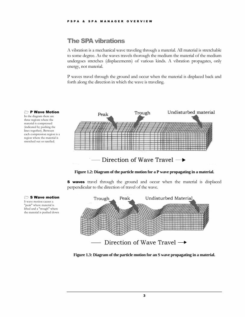
The SPA vibrations
A vibration is a mechanical wave traveling through a material. All material is stretchable to some degree. As the waves travels thorough the medium the material of the medium undergoes stretches (displacements) of various kinds. A vibration propagates, only energy, not material.
P waves travel through the ground and occur when the material is displaced back and forth along the direction in which the wave is traveling.
Figure 1.2: Diagram of the particle motion for a P wave propagating in a material.
S waves travel through the ground and occur when the material is displaced perpendicular to the direction of travel of the wave.
Figure 1.3: Diagram of the particle motion for an S wave propagating in a material.
P Wave Motion
In the diagram there are three regions where the material is compressed (indicated by pushing the lines together). Between each compression region is a region where the material is stretched out or rarefied.
S Wave motion
S wave motion causes a "peak" where material is lifted and a "trough" where the material is pushed down
P S P A & S P A M A N A G E R O V E R V I E W
4
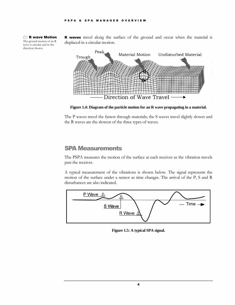
R waves travel along the surface of the ground and occur when the material is displaced in a circular motion.
Figure 1.4: Diagram of the particle motion for an R wave propagating in a material.
The P waves travel the fastest through materials; the S waves travel slightly slower and the R waves are the slowest of the three types of waves.
SPA Measurements
The PSPA measures the motion of the surface at each receiver as the vibration travels past the receiver.
A typical measurement of the vibrations is shown below. The signal represents the motion of the surface under a sensor as time changes. The arrival of the P, S and R disturbances are also indicated.
Figure 1.5: A typical SPA signal.
R wave Motion
The ground motion of an R wave is circular and in the direction shown.
P S P A & S P A M A N A G E R O V E R V I E W
5
The SPA Manager will reduce measurements (records in time) taken at the two receivers and then analyze these results to determine a seismic modulus and thickness for the surface layer.
The seismic modulus is a measure of the resistance of a solid to a change in its length. The larger the value of modulus for a material the stiffer the material is.
The analysis can be done by either inspecting the SPA time records, or can be performed in the frequency domain using the Ultrasonic Surface Waves (USW) and Impact Echo (IE) methods.
Ultrasonic Surface Wave Method – the Seismic
Modulus
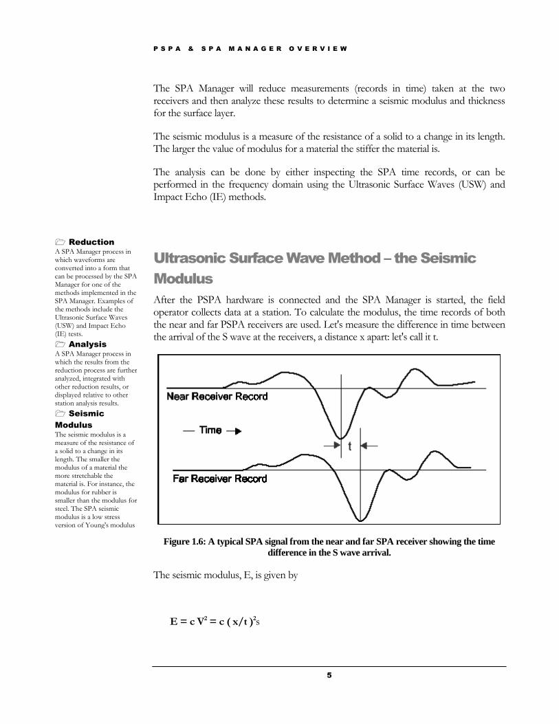
After the PSPA hardware is connected and the SPA Manager is started, the field operator collects data at a station. To calculate the modulus, the time records of both the near and far PSPA receivers are used. Let's measure the difference in time between the arrival of the S wave at the receivers, a distance x apart: let's call it t.
Figure 1.6: A typical SPA signal from the near and far SPA receiver showing the time
difference in the S wave arrival.
The seismic modulus, E, is given by
E = c V2 = c ( x/t )2s
Reduction
A SPA Manager process in which waveforms are converted into a form that can be processed by the SPA Manager for one of the methods implemented in the SPA Manager. Examples of the methods include the Ultrasonic Surface Waves (USW) and Impact Echo (IE) tests.
Analysis
A SPA Manager process in which the results from the reduction process are further analyzed, integrated with other reduction results, or displayed relative to other station analysis results.
Seismic
Modulus
The seismic modulus is a measure of the resistance of a solid to a change in its length. The smaller the modulus of a material the more stretchable the material is. For instance, the modulus for rubber is smaller than the modulus for steel. The SPA seismic modulus is a low stress version of Young's modulus
P S P A & S P A M A N A G E R O V E R V I E W
6
since the speed of the S wave between the two receivers is given by distance divided by time and c is a constant.
The SPA Manager actually reduces the data using the Ultrasonic Surface Wave (USW) method to obtain more comprehensive results. The USW method decomposes (Fourier Transforms) the SPA time record into components of different frequencies and analyzes each frequency component.
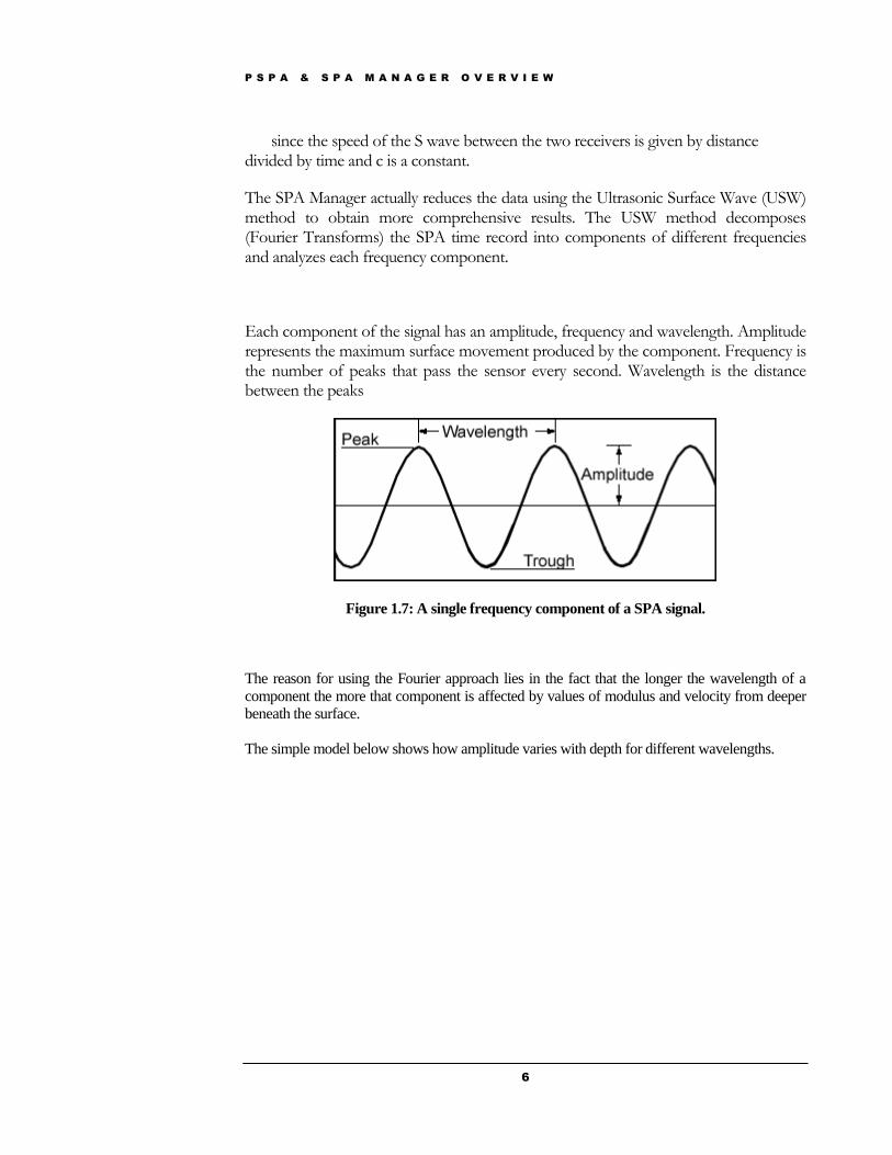
Each component of the signal has an amplitude, frequency and wavelength. Amplitude represents the maximum surface movement produced by the component. Frequency is the number of peaks that pass the sensor every second. Wavelength is the distance between the peaks
Figure 1.7: A single frequency component of a SPA signal.
The reason for using the Fourier approach lies in the fact that the longer the wavelength of a
component the more that component is affected by values of modulus and velocity from deeper
beneath the surface.
The simple model below shows how amplitude varies with depth for different wavelengths.
P S P A & S P A M A N A G E R O V E R V I E W
7
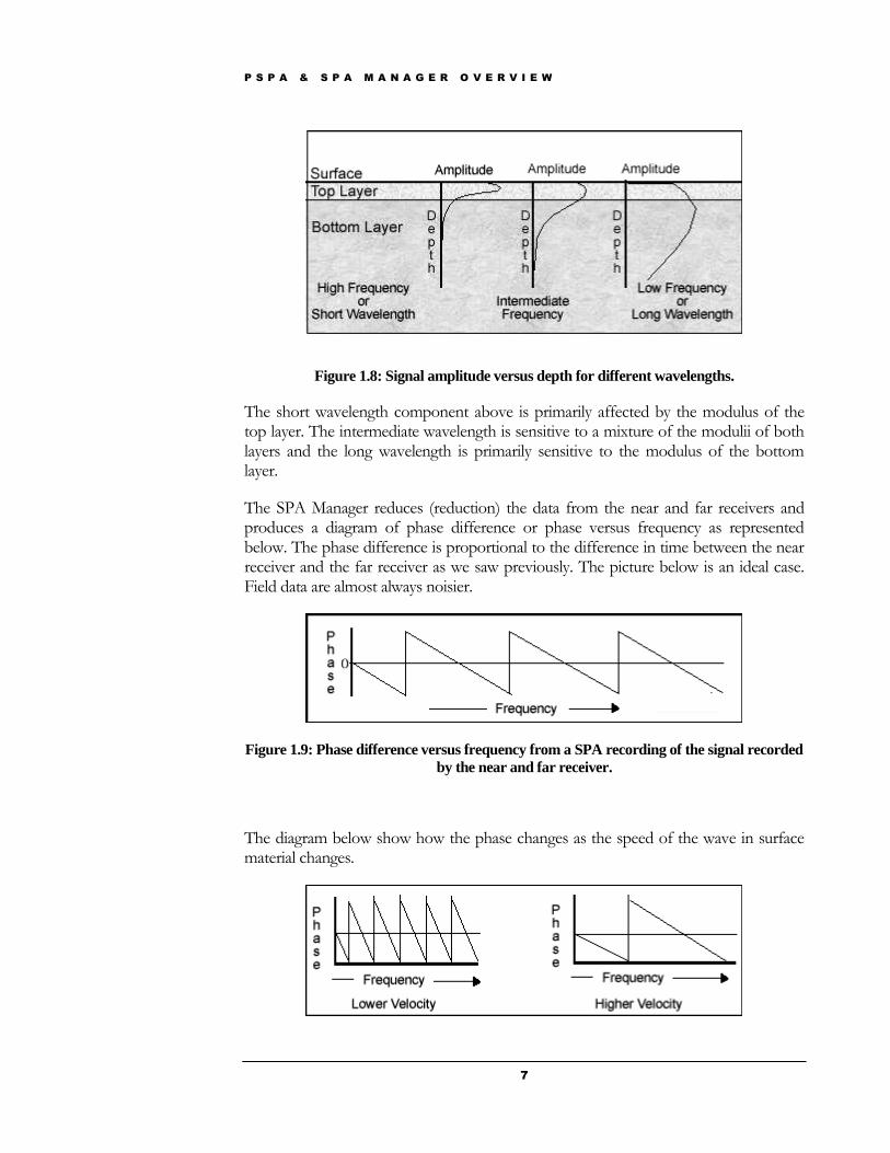
Figure 1.8: Signal amplitude versus depth for different wavelengths.
The short wavelength component above is primarily affected by the modulus of the top layer. The intermediate wavelength is sensitive to a mixture of the modulii of both layers and the long wavelength is primarily sensitive to the modulus of the bottom layer.
The SPA Manager reduces (reduction) the data from the near and far receivers and produces a diagram of phase difference or phase versus frequency as represented below. The phase difference is proportional to the difference in time between the near receiver and the far receiver as we saw previously. The picture below is an ideal case. Field data are almost always noisier.
Figure 1.9: Phase difference versus frequency from a SPA recording of the signal recorded
by the near and far receiver.
The diagram below show how the phase changes as the speed of the wave in surface material changes.
P S P A & S P A M A N A G E R O V E R V I E W
8
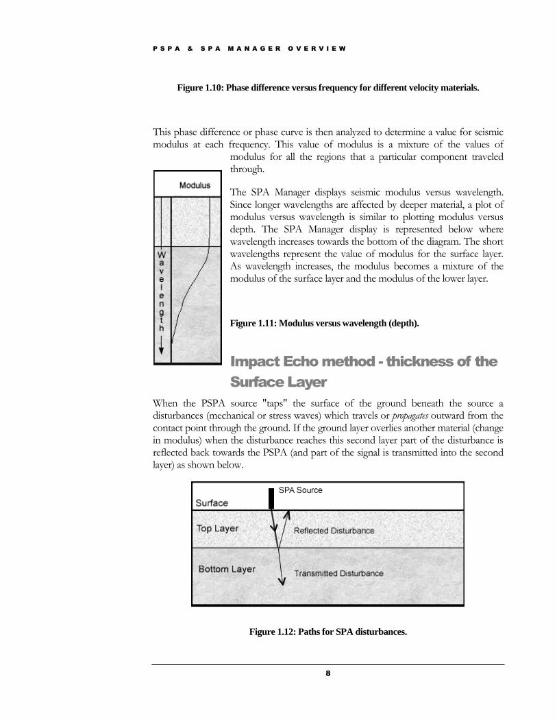
Figure 1.10: Phase difference versus frequency for different velocity materials.
This phase difference or phase curve is then analyzed to determine a value for seismic modulus at each frequency. This value of modulus is a mixture of the values of
modulus for all the regions that a particular component traveled through.
The SPA Manager displays seismic modulus versus wavelength. Since longer wavelengths are affected by deeper material, a plot of modulus versus wavelength is similar to plotting modulus versus depth. The SPA Manager display is represented below where wavelength increases towards the bottom of the diagram. The short wavelengths represent the value of modulus for the surface layer. As wavelength increases, the modulus becomes a mixture of the modulus of the surface layer and the modulus of the lower layer.
Figure 1.11: Modulus versus wavelength (depth).
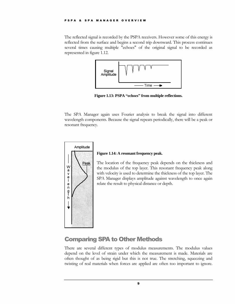
Impact Echo method - thickness of the
Surface Layer
When the PSPA source "taps" the surface of the ground beneath the source a disturbances (mechanical or stress waves) which travels or propagates outward from the contact point through the ground. If the ground layer overlies another material (change in modulus) when the disturbance reaches this second layer part of the disturbance is reflected back towards the PSPA (and part of the signal is transmitted into the second layer) as shown below.
Figure 1.12: Paths for SPA disturbances.
P S P A & S P A M A N A G E R O V E R V I E W
9
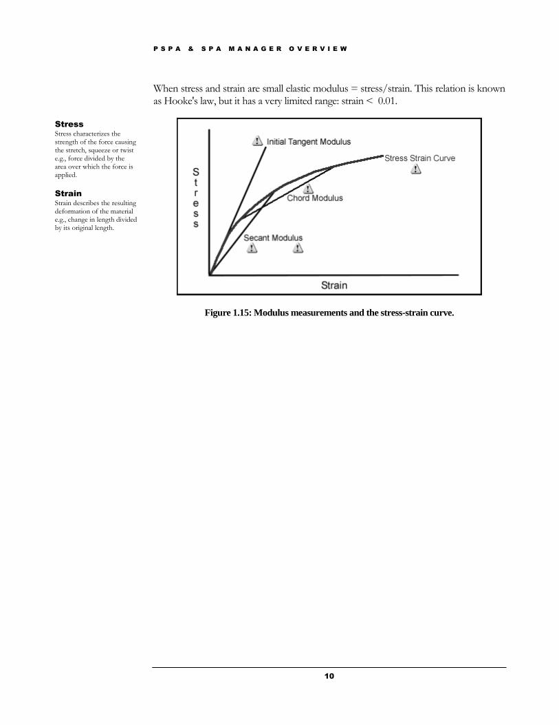
The reflected signal is recorded by the PSPA receivers. However some of this energy is reflected from the surface and begins a second trip downward. This process continues several times causing multiple "echoes" of the original signal to be recorded as represented in figure 1.12.
Figure 1.13: PSPA “echoes” from multiple reflections.
The SPA Manager again uses Fourier analysis to break the signal into different wavelength components. Because the signal repeats periodically, there will be a peak or resonant frequency.
Figure 1.14: A resonant frequency peak.
The location of the frequency peak depends on the thickness and the modulus of the top layer. This resonant frequency peak along with velocity is used to determine the thickness of the top layer. The SPA Manager displays amplitude against wavelength to once again relate the result to physical distance or depth.
Comparing SPA to Other Methods
There are several different types of modulus measurements. The modulus values depend on the level of strain under which the measurement is made. Materials are often thought of as being rigid but this is not true. The stretching, squeezing and twisting of real materials when forces are applied are often too important to ignore.
P S P A & S P A M A N A G E R O V E R V I E W
10
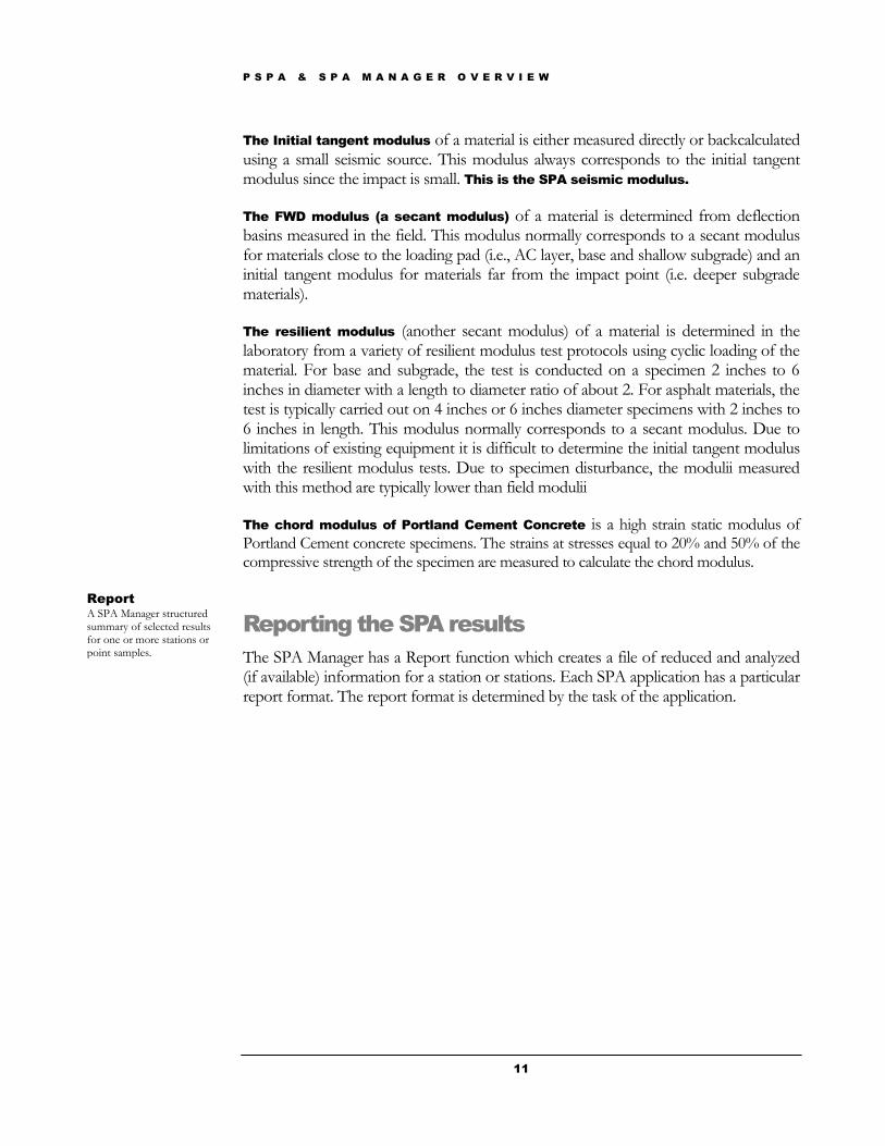
When stress and strain are small elastic modulus = stress/strain. This relation is known as Hooke's law, but it has a very limited range: strain < 0.01.
Figure 1.15: Modulus measurements and the stress-strain curve.
Stress
Stress characterizes the strength of the force causing the stretch, squeeze or twist e.g., force divided by the area over which the force is applied.
Strain
Strain describes the resulting deformation of the material e.g., change in length divided by its original length.
P S P A & S P A M A N A G E R O V E R V I E W
11
The Initial tangent modulus of a material is either measured directly or backcalculated using a small seismic source. This modulus always corresponds to the initial tangent modulus since the impact is small. This is the SPA seismic modulus.
The FWD modulus (a secant modulus) of a material is determined from deflection basins measured in the field. This modulus normally corresponds to a secant modulus for materials close to the loading pad (i.e., AC layer, base and shallow subgrade) and an initial tangent modulus for materials far from the impact point (i.e. deeper subgrade materials).
The resilient modulus (another secant modulus) of a material is determined in the laboratory from a variety of resilient modulus test protocols using cyclic loading of the material. For base and subgrade, the test is conducted on a specimen 2 inches to 6 inches in diameter with a length to diameter ratio of about 2. For asphalt materials, the test is typically carried out on 4 inches or 6 inches diameter specimens with 2 inches to 6 inches in length. This modulus normally corresponds to a secant modulus. Due to limitations of existing equipment it is difficult to determine the initial tangent modulus with the resilient modulus tests. Due to specimen disturbance, the modulii measured with this method are typically lower than field modulii
The chord modulus of Portland Cement Concrete is a high strain static modulus of Portland Cement concrete specimens. The strains at stresses equal to 20% and 50% of the compressive strength of the specimen are measured to calculate the chord modulus.
Reporting the SPA results
The SPA Manager has a Report function which creates a file of reduced and analyzed (if available) information for a station or stations. Each SPA application has a particular report format. The report format is determined by the task of the application.
Report
A SPA Manager structured summary of selected results for one or more stations or point samples.
P S P A & S P A M A N A G E R O V E R V I E W
12
SPA Application Workflow
1. Set up the hardware: Go to Chapter 2 Starting the SPA of this manual.
2. Start the SPA Manager: Start SPA Manager by pressing the SPA icon on the desktop.
3. Choose appropriate options about the PSPA equipment and results that are required: Go to chapter 3 SPA Options of this manual.
4. Go through a project and site setup in which the following are chosen:
a. A particular SPA Manager application
b. A name for your SPA project,
c. A name for your SPA site,
d. Set the structure and material properties for this site.
Go to chapter 4 SPA Projects & Sites to see this portion of the manual.
5. Collect data at a series of stations at various sites: Go to chapter 5 SPA
Stations to start this tutorial. You can generate a SPA Manager report of the results of the analysis for each station of site.
6. Maintain the PSPA equipment: Go to chapter 6 SPA Maintenance to start this portion of the manual.
Not all of these step have be performed every day. As we go further in this tutorial you will see how these steps work together.
S T A R T I N G T H E S P A
13
Starting the SPA
Setting up the PSPA hardware.
The PSPA hardware consists of a source, a near and far receiver and an
electronics box. The source, receivers and the electronics box are mounted on rails to create a hand portable unit. Two versions are pictured. The PSPA-P is the parallel-port version and the PSPA-PU is the USB version
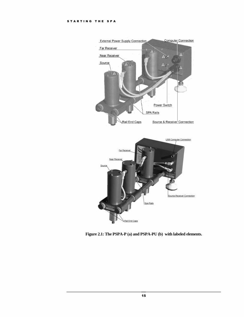
The external power connection PSPS-P: A connector for the external power supply. When the external power supply is connected the PSPA batteries stored in the electronics box are charged (Fig 2.1a).
The external power connection PSPS-PU: External power is supplied through the USB cable from the computer batteries. No internal batteries are present (Fig 2.1b).
Near and Far Receiver: The two vertical cylinders closest to the PSPA electronics box contain the PSPA receivers. Each receiver contains a seismic accelerometer to measure the movement of the surface material under the receiver.
Source: The vertical cylinder furthest from the PSPA electronics box is contains the PSPA electric solenoid seismic source.
Power Switch PSPA-P: The power switch is:
ON: when switch is towards the center of the electronics box and
OFF when the switch is towards the outer edge of the electronics box.
Power Switch PSPA-PU: No power switch is present. Simply unplug the USB cable from the computer at any time to turn off the PSPA-PU.
Chapter
2

S T A R T I N G T H E S P A
14
Source and Receiver Connection: The lower outside corner of the electronics box has an 18 pin male socket (PSPA-P), or four and five-pin mail connectors (PSPA-PU) that connects source and receivers to the electronics box. This connector sends vibration and firing signals back and forth and must be connected for proper operation.
Computer Connection: The upper corner of the electronics box holds an 18 pin female socket (PSPA-P), or a 4-pin female socket (PSPA-PU) for connecting the computer's port to the electronics box. A special connecting cable is provided with the PSPA for this connection.
S T A R T I N G T H E S P A
15
Figure 2.1: The PSPA-P (a) and PSPA-PU (b) with labeled elements.
S T A R T I N G T H E S P A
16
Charging the PSPA-P Batteries
Using an External Power Source
The PSPA-P is supplied with an external AC power source. The PSPA batteries will generally run for several days of routine data collection of four hundred stations per day on a single full charge.
Normal daily operation of the PSPA must include recharging by the external AC power source at night.
To recharge, connect the external AC power source to the connector located above the power switch on the front face of the electronics box to recharge the PSPA's internal batteries.
When an external power supply is connected, the PSPA will attempt to recharge its internal batteries. The PSPA can be operated during recharging as long as batteries
are undamaged.
The remaining battery life in terms of the number of stations remaining will be continuously indicated in the SPA Manager Battery area.
Caution
SEVERE DAMAGE CAN RESULT IF OTHER BATTERY CONFIGURATIONS OR RECHARGING SOURCES ARE USED.
For further information on batteries, press the "Maintenance" button to the left and then press "Battery Options" on the Maintenance main menu. There are specific cautions with regard to recharging or general use.
The standard PSPA battery configuration uses 10 NiMH AA batteries mounted in the back of the electronics box. Do not leave the external AC power source recharging the NiMH batteries for more than 15 hours, as the batteries may be damaged.
S T A R T I N G T H E S P A
17
Recharging in the Field
Another battery charging option is to connect the PSPA-P to an automobile cigarette lighter outlet, either with or without the vehicle running. The PSPA is supplied with this type of connector.
The auto battery can recharge the PSPA battery pack somewhat faster than the line charger, as quickly as 6 hours.
If the engine is not running, the auto battery will recharge the PSPA batteries and can be left on indefinitely, with no damage to the batteries.
With the engine running, the PSPA should be connected less than 15 hours.
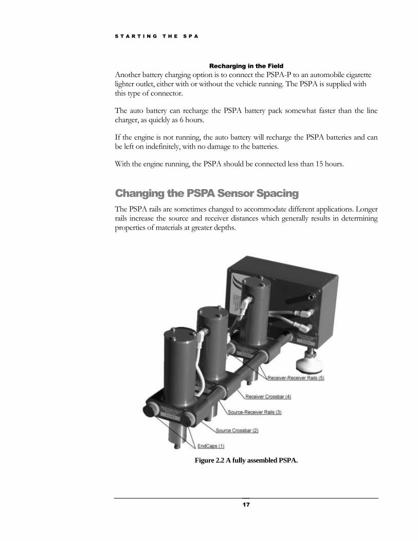
Changing the PSPA Sensor Spacing
The PSPA rails are sometimes changed to accommodate different applications. Longer rails increase the source and receiver distances which generally results in determining properties of materials at greater depths.
Figure 2.2 A fully assembled PSPA.
S T A R T I N G T H E S P A
18
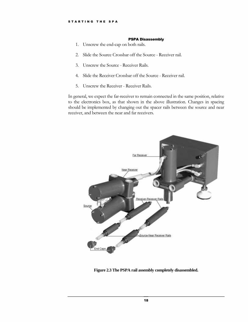
PSPA Disassembly
1. Unscrew the end-cap on both rails.
2. Slide the Source Crossbar off the Source - Receiver rail.
3. Unscrew the Source - Receiver Rails.
4. Slide the Receiver Crossbar off the Source - Receiver rail.
5. Unscrew the Receiver - Receiver Rails.
In general, we expect the far-receiver to remain connected in the same position, relative to the electronics box, as that shown in the above illustration. Changes in spacing should be implemented by changing out the spacer rails between the source and near receiver, and between the near and far receivers.
Figure 2.3 The PSPA rail assembly completely disassembled.
S T A R T I N G T H E S P A
19
PSPA Reassembly
Reverse the procedure above for reassembly.
In reassembling the rails, do not use hand tools, or attempt to over-tighten. In screwing in a rail, tight is when the rail flange touches the nylon bushing on the air cylinder.
DO NOT TURN EVEN 1/16 OF A TURN FURTHER AFTER THE BUSHINGS TOUCH.
Additional tightening will cause the vibration isolation between the receivers to deteriorate. Hint: Coat your hands with silicone grease if you are prone to crushing hands during handshakes.
Connecting PSPA
Figure 2.5 shows a view of the PSPA from the PSPA source, looking back towards the electronics box.
Connect the PSPA in the following sequence:
1. Make certain the computer is turned off.
2. Make certain the power switch on the PSPA electronics box is off.
In the "OFF" position the toggle switch points toward the outer edge of the electronics
box.
3. Connect the source and receivers to the electronics box: There are three connections to
be made.
The shortest wire is terminated in an 8-pin plug, and this is plugged into the Far
Receiver cylinder, nearest the electronics box.
The two remaining wires are terminated in 3 pin plugs, and connect the two remaining
cylinders to the electronics box. In general, the shorter wire should only reach the Near
Receiver cylinder, while the longer cable should connect to the Source cylinder. The
extra wire length for the source and Receiver A allows enough length for changing
spacers in between the cylinders for a different pavement thickness.
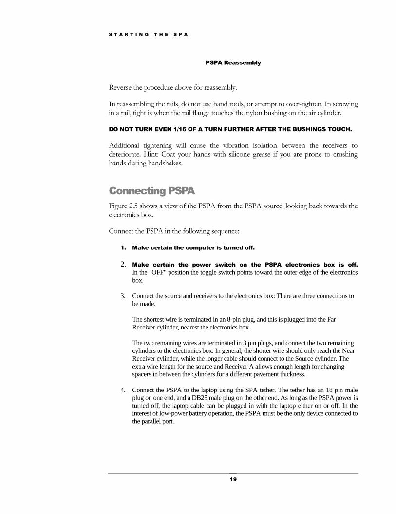
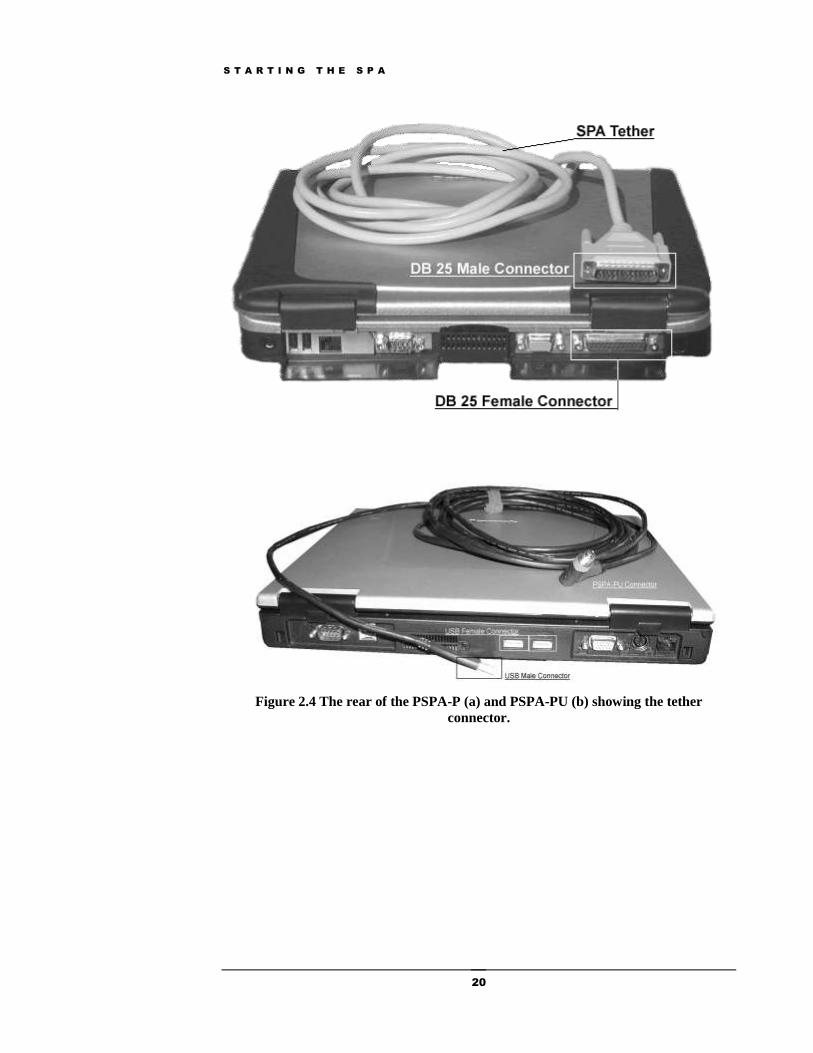
4. Connect the PSPA to the laptop using the SPA tether. The tether has an 18 pin male
plug on one end, and a DB25 male plug on the other end. As long as the PSPA power is
turned off, the laptop cable can be plugged in with the laptop either on or off. In the
interest of low-power battery operation, the PSPA must be the only device connected to
the parallel port.
S T A R T I N G T H E S P A
20
Figure 2.4 The rear of the PSPA-P (a) and PSPA-PU (b) showing the tether
connector.

S T A R T I N G T H E S P A
21
Deploying the PSPA
The PSPA-P power switch should be turned on only after connecting the PSPA
tether to the computer. If you connect the PSPA to a powered up laptop, the PSPA may cycle out of its low-power standby mode upon connection to the laptop. This would result in premature battery drain, heating of the electronics, and other annoying problems in the field (where you least need them).
To maintain high quality data for an individual station, care should be take to ensure the receiver foot is well-seated on the pavement. The PSPA can either be set down vertically, or the PSPA can be placed on the ground in the following manner.
1. Place the PSPA carefully on the ground with both of the feet below the electronics box touching the ground.
Figure 2.5 The PSPA before it is lowered to the ground.
S T A R T I N G T H E S P A
22
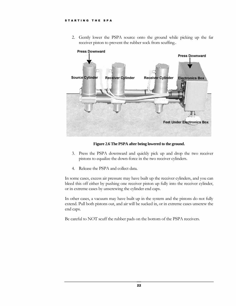
2. Gently lower the PSPA source onto the ground while picking up the far receiver piston to prevent the rubber sock from scuffing..
Figure 2.6 The PSPA after being lowered to the ground.
3. Press the PSPA downward and quickly pick up and drop the two receiver pistons to equalize the down-force in the two receiver cylinders.
4. Release the PSPA and collect data.
In some cases, excess air pressure may have built up the receiver cylinders, and you can bleed this off either by pushing one receiver piston up fully into the receiver cylinder, or in extreme cases by unscrewing the cylinder end caps.
In other cases, a vacuum may have built up in the system and the pistons do not fully extend. Pull both pistons out, and air will be sucked in, or in extreme cases unscrew the end caps.
Be careful to NOT scuff the rubber pads on the bottom of the PSPA receivers.
S T A R T I N G T H E S P A
23
Starting the SPA Manager
There are three methods for starting the Spa Manager software.
1. Double click the SPA Manager icon. If the SPA Manager desktop icon does not exist, it can be selected from the Start-Program menu, or a link can be established from the desktop to the executable in C:\Program Files\GrdSpa\RdfMgr.exe. This will open up the SPA Manager software on the last accessed site file.
2. Drag the icon for a preexisting site file that you want to open onto the Spa Manager icon.
3. Double-click a preexisting site file. The “.sit” extension must be linked to the Spa Manager program in the registry, and the .sit extension may already be used by some other program on your computer.
There are three possible action sequences (workflows) based on status of the PSPA hardware.
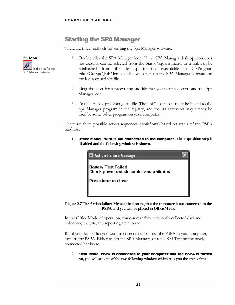
1. Office Mode: PSPA is not connected to the computer - the acquisition step is
disabled and the following window is shown.
Figure 2.7 The Action failure Message indicating that the computer is not connected to the
PSPA and you will be placed in Office Mode.
In the Office Mode of operation, you can reanalyze previously collected data and reduction, analysis, and reporting are allowed. But if you decide that you want to collect data, connect the PSPA to your computer, turn on the PSPA. Either restart the SPA Manager, or run a Self-Test on the newly connected hardware.
2. Field Mode: PSPA is connected to your computer and the PSPA is turned
on, you will see one of the two following window which tells you the state of the.
Icon
Is the icon for the SPA Manager software.
S T A R T I N G T H E S P A
24
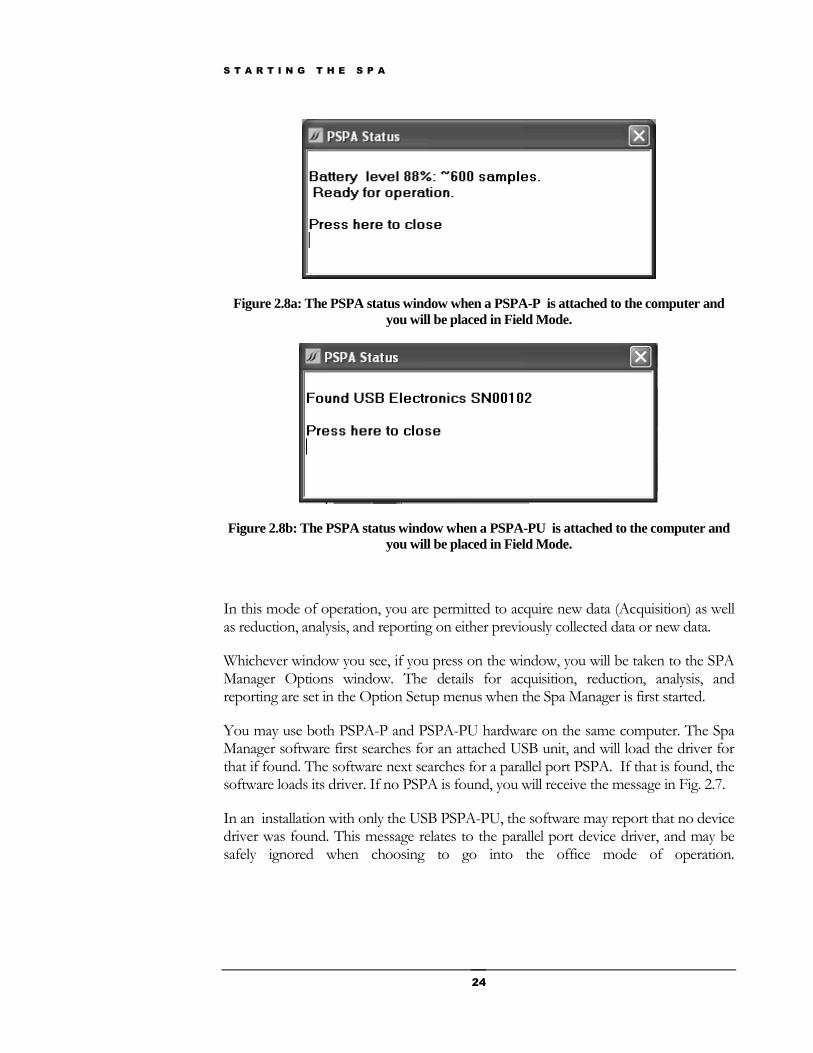
Figure 2.8a: The PSPA status window when a PSPA-P is attached to the computer and
you will be placed in Field Mode.
Figure 2.8b: The PSPA status window when a PSPA-PU is attached to the computer and
you will be placed in Field Mode.
In this mode of operation, you are permitted to acquire new data (Acquisition) as well as reduction, analysis, and reporting on either previously collected data or new data.
Whichever window you see, if you press on the window, you will be taken to the SPA Manager Options window. The details for acquisition, reduction, analysis, and reporting are set in the Option Setup menus when the Spa Manager is first started.
You may use both PSPA-P and PSPA-PU hardware on the same computer. The Spa Manager software first searches for an attached USB unit, and will load the driver for that if found. The software next searches for a parallel port PSPA. If that is found, the software loads its driver. If no PSPA is found, you will receive the message in Fig. 2.7.
In an installation with only the USB PSPA-PU, the software may report that no device driver was found. This message relates to the parallel port device driver, and may be safely ignored when choosing to go into the office mode of operation.
S P A O P T I O N S
25
SPA Options
Setting the options for the SPA for successful field work
No matter whether you are in field mode or office mode, you will next enter the SPA Manager Options window. In the Options window, here are four types of options that can be set:
1. Start Options
2. Setup Options
3. Instrument Options and
4. Properties Options.
The SPA Start Options
Figure 3.1 shows the Start Options tab. Note that pressing on the other tabs will take you to the Help for those pages when viewing the actual SPA .Manager.
Chapter
3
S P A O P T I O N S
26
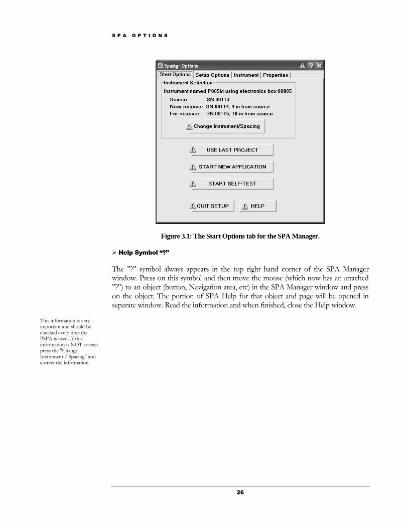
Figure 3.1: The Start Options tab for the SPA Manager.
Help Symbol “?”
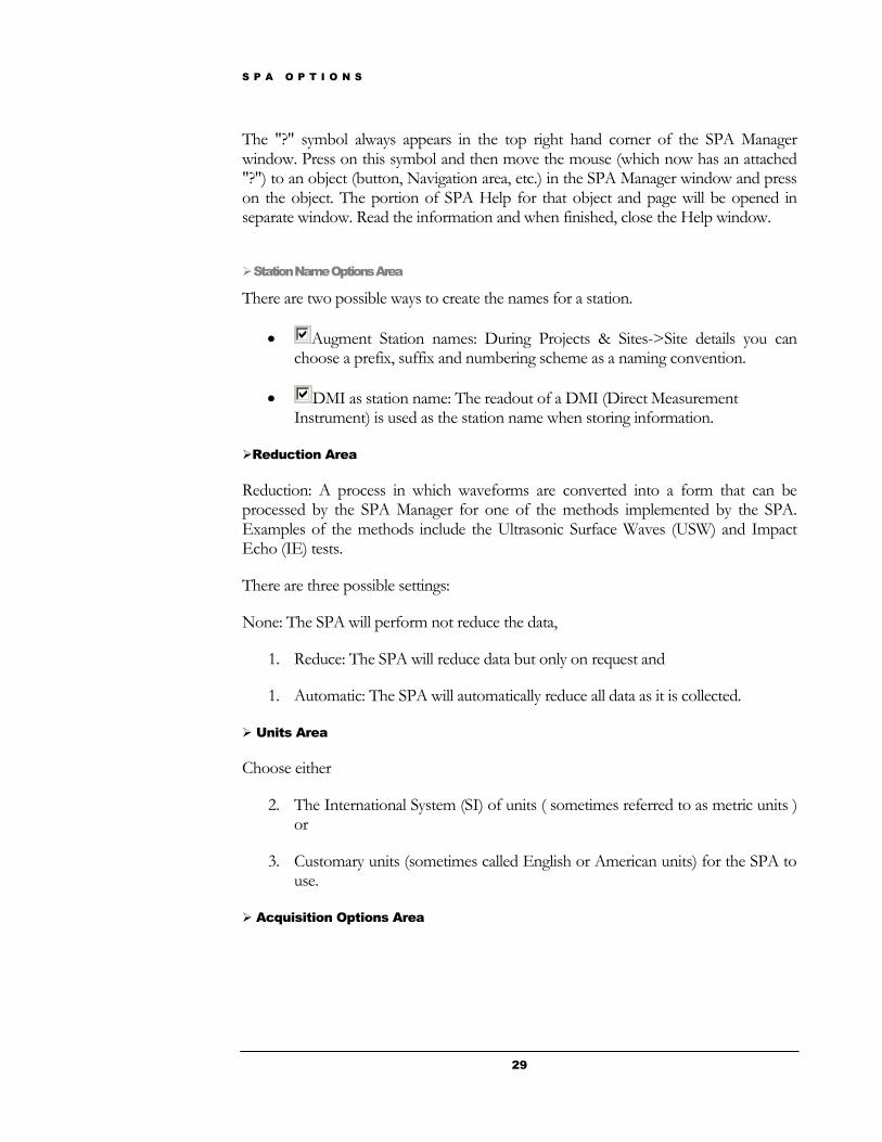
The "?" symbol always appears in the top right hand corner of the SPA Manager window. Press on this symbol and then move the mouse (which now has an attached "?") to an object (button, Navigation area, etc) in the SPA Manager window and press on the object. The portion of SPA Help for that object and page will be opened in separate window. Read the information and when finished, close the Help window.
This information is very important and should be checked every time the PSPA is used. If this information is NOT correct press the "Change Instrument / Spacing" and correct the information.
S P A O P T I O N S
27
Instrument Selection Area
The Start Options displays hardware options which SPA Manager will use in field operations. Different pieces of equipment have different responses so it is necessary that the SPA Manager is informed of the present equipment.
1. The "name" of the PSPA: P005M in the example above.
2. The serial number of the electronics box: 00005
3. The serial number of the PSPA source: SN00113
4. The serial number of the near receiver: SN 00114
5. The distance of the near receiver from the source: 4 inches from source
6. The serial number of the far receiver: SN 00115
7. The distance of the far receiver from the source: 10 inches from source.
Use Last Project Button
This will be the usual button pressed when doing field work. Pressing this button will take you directly to the "SPA Stations" page of the SPA Manager for further collection of data at the last project and site.
Be sure to check that the serial numbers and spacings are correct before pressing this button when you are in the field.
Start New Application Button
Press this button to start the SPA Manager and use a new application.
Application: A SPA Manager method to create a user-friendly setup, data acquisition, reduction, analysis and reporting for different uses of the SPA. Examples of Applications include estimating flexural strength of airfields, quantifying the curing of concrete with time, determining the quality of the asphalt concrete layer.
Pressing this button will take you to the "Select an Application" page (part of SPA Projects / Sites) where you will be able to a new application and project. Be sure to check that the serial numbers and spacings are correct before pressing this button when you are in the field.
For further information go to Chapter 4 "SPA Projects and Sites”.
Start Self Test Button
S P A O P T I O N S
28
The successful Self-Test will trigger the PSPA source once and report the battery level. This test is necessary to set the Acquisition mode in the Spa Manager.
If the PSPA not connected the Spa Manager will be put into Reduction mode. This is your opportunity to check instrument serial number and receiver spacing.
Quit Setup Button
Press this button when all information has been checked.
Exiting here will not start the Spa Manager and will lose any unsaved option changes.
The SPA Setup Options
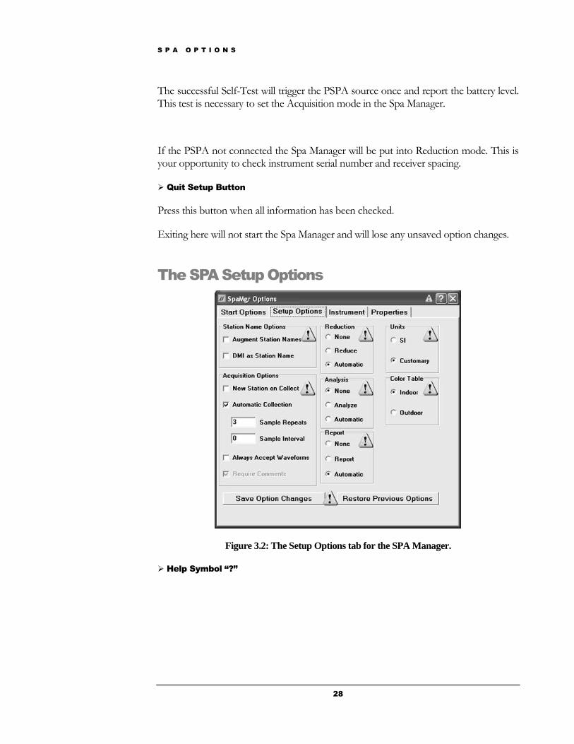
Figure 3.2: The Setup Options tab for the SPA Manager.
Help Symbol “?”
S P A O P T I O N S
29
The "?" symbol always appears in the top right hand corner of the SPA Manager window. Press on this symbol and then move the mouse (which now has an attached "?") to an object (button, Navigation area, etc.) in the SPA Manager window and press on the object. The portion of SPA Help for that object and page will be opened in separate window. Read the information and when finished, close the Help window.
Station Name Options Area
There are two possible ways to create the names for a station.
Augment Station names: During Projects & Sites->Site details you can choose a prefix, suffix and numbering scheme as a naming convention.
DMI as station name: The readout of a DMI (Direct Measurement Instrument) is used as the station name when storing information.
Reduction Area
Reduction: A process in which waveforms are converted into a form that can be processed by the SPA Manager for one of the methods implemented by the SPA. Examples of the methods include the Ultrasonic Surface Waves (USW) and Impact Echo (IE) tests.
There are three possible settings:
None: The SPA will perform not reduce the data,
1. Reduce: The SPA will reduce data but only on request and
1. Automatic: The SPA will automatically reduce all data as it is collected.
Units Area
Choose either
2. The International System (SI) of units ( sometimes referred to as metric units ) or
3. Customary units (sometimes called English or American units) for the SPA to use.
Acquisition Options Area

S P A O P T I O N S
30
New Station on Collect: Create a new station every time the Repeat Collect button is pressed (See SPA Stations for data collection).
Automatic Collection: Collect data automatically over a period of time using the information from the two following boxes to control quantity and timing.
Sample Repeats: During automatic collection of data capture N samples of SPA data, where N is the number in this box. The samples will be M seconds apart.
Sample Interval: During automatic collection of data, capture SPA data every M seconds where M is the number in this box.
Always Accept Waveforms: Whenever the Repeat Collect button is pressed automatically accept (i.e. save) the waveforms.
Analysis Area
Analysis: A process in which the results from the reduction process are further analyzed, integrated with other reduction results, or displayed relative to other station analysis results.
There are three possible settings:
1. None: The SPA Manager will perform no analysis on data
2. Analyze: The SPA Manager will perform an analysis but only on demand and
3. Automatic: The SPA Manager will automatically perform analysis on all data as it is collected.
Color Table
To reduce eyestrain, the SPA Manager can be configured for either
Indoor use (Color pages for desktop work) or
Outdoor use (Black and white high contrast pages).
Report Area

S P A O P T I O N S
31
Report: A structured summary of selected pavement attributes for one or more stations or point samples.
There are three possible settings:
1. None: The SPA Manager will make no report on the data
2. Report: The SPA Manager will make a report but only on request and
3. Automatic: The SPA Manager will automatically make a report on all data as it is collected.
Save Option Changes & Restore Previous Options Buttons
There are two options:
1. "Save Option Changes" button and all information on this panel is saved and used by the SPA Manager, or
2. “Restore Previous Options" button to retain the original settings for this panel.
The PSPA Instrument Options
Figure 3.3: The Instrument Options tab for the SPA Manager.
Help Symbol “?”
The "?" symbol always appears in the top right hand corner of the SPA Manager window. Press on this symbol and then move the mouse (which now has an attached "?") to an object (button, Navigation area, etc.) in the SPA Manager window and press on the object. The portion of SPA Help for that object and page will be opened in separate window. Read the information and when finished, close the Help window.
S P A O P T I O N S
32
Select Serial Number Area
Confirm Spacings Area
Check that the serial number of your PSPA's source matches the number shown by the SPA Manager in the first row of the table.
Check that the serial number of your PSPA's nearest receiver matches the number shown by the SPA Manager in the second row of the table.
Check that the serial number of your PSPA's farthest receiver matches the number shown by the SPA Manager in the third row of the table.
If any of these numbers do not match, press the incorrect table entry and select the correct number for your instrument.
Save Changes Area
You can either
Save the changes on this tab by pressing the "Save" button or
Cancel any changes on this tab you have made by pressing the "Cancel" button.
S P A O P T I O N S
33
The SPA Properties Options
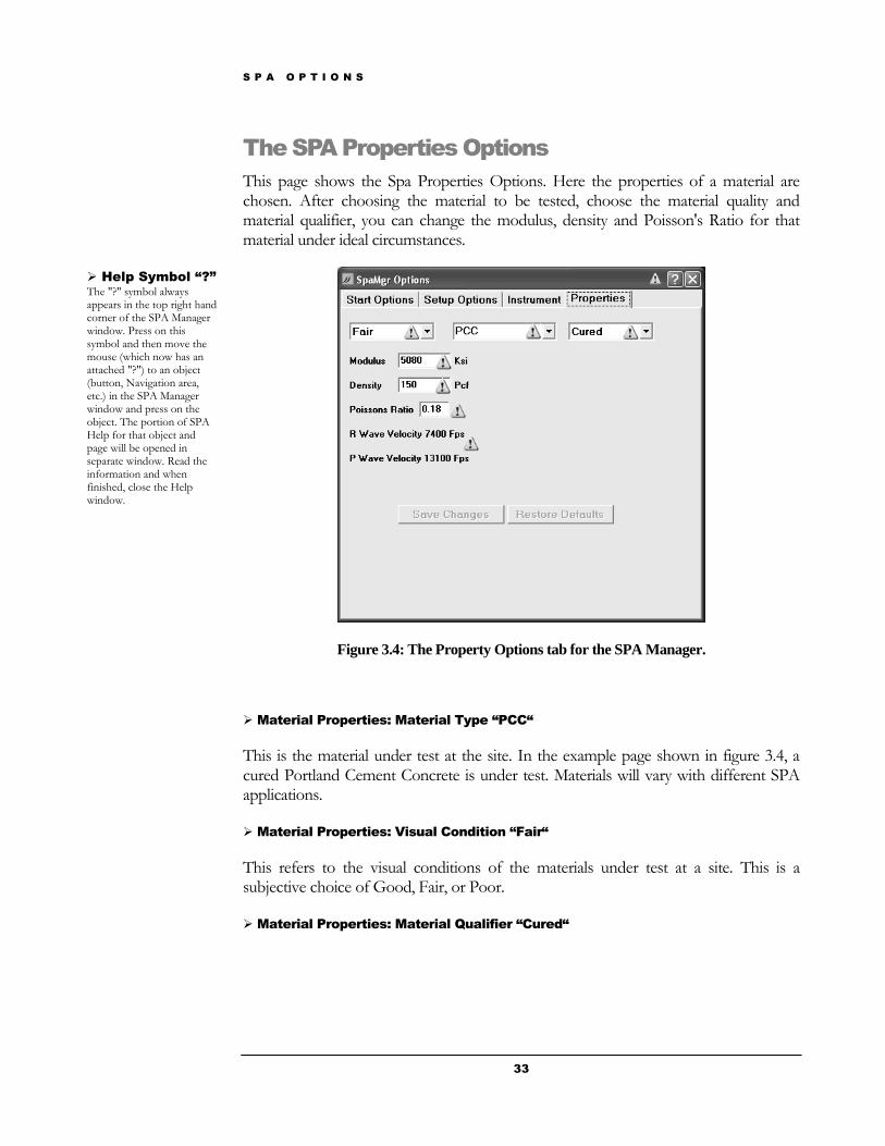
This page shows the Spa Properties Options. Here the properties of a material are chosen. After choosing the material to be tested, choose the material quality and material qualifier, you can change the modulus, density and Poisson's Ratio for that material under ideal circumstances.
Figure 3.4: The Property Options tab for the SPA Manager.
Material Properties: Material Type “PCC“
This is the material under test at the site. In the example page shown in figure 3.4, a cured Portland Cement Concrete is under test. Materials will vary with different SPA applications.
Material Properties: Visual Condition “Fair“
This refers to the visual conditions of the materials under test at a site. This is a subjective choice of Good, Fair, or Poor.
Material Properties: Material Qualifier “Cured“
Help Symbol “?”
The "?" symbol always appears in the top right hand corner of the SPA Manager window. Press on this symbol and then move the mouse (which now has an attached "?") to an object (button, Navigation area, etc.) in the SPA Manager window and press on the object. The portion of SPA Help for that object and page will be opened in separate window. Read the information and when finished, close the Help window.
S P A O P T I O N S
34
This is a qualifier to further define the material presently listed in the center box. In this example PCC, the material, can be either "cured" or "fresh". Every material will have a different set of qualifiers.
Material Properties: Modulus
This is the expected seismic modulus for the material, quality of the material and condition chosen above. The units are shown at the side and are the units chosen on the Setup Options page. You can change this property by selecting the number and typing in another number.
Material Properties: Density
This is the assumed density for the material and quality chosen above. The units are listed beside the box. These units are the units chosen on the Setup Options tab.
To change the value of the ideal density: select the number and enter a new value.
Material Properties: Poisson’s Ratio
The number shown is Poisson's Ratio for the material, visual condition and visual condition chosen above.
This value may be changed by selecting the number and entering a new number.
Material Properties: Wave Velocities
The P and R wave velocity for the material and condition chosen above. The units were chosen on the Setup Options tab.

S P A P R O J E C T S A N D S I T E S
35
SPA Projects and Sites
How to set up a new project and site
Selecting an Application
After the SPA Manager Options have been completed, if you pressed Start New
application, you are taken to the SPA Manager page shown in figure 4.1 to select an application.
Figure 4.1: Select an Application Page of the SPA Manager
Chapter
4
Application: A SPA Manager module encompassing a user-friendly setup, data acquisition, reduction, analysis and reporting for a particular use of the SPA. Examples of Applications include estimating flexural strength of airfields, quantifying the curing of concrete with time, determining the quality of the asphalt concrete layer, etc.
S P A P R O J E C T S A N D S I T E S
36
Select your application by using the list box in the input area.
The possible SPA applications are
PCC-AC Modulus: Estimate seismic modulus of PCC or AC materials
Base-Subgrade Modulus: Estimate modulus of granular materials
PCC Quality: Estimate modulus ( and thickness ) of PCC
AC Quality: Estimate modulus and thickness of a single paving layer over a base
Go/No Go: Application for Geomedia prototype hardware
Curing: This application under construction
Project Caption “Undefined Application”
This area will contain the information about where the SPA Manager stores the data for the project. As you will see in future pages of the SPA Help, this caption will be "built up" as the project is defined.
In figure 4.1, there is no information because no Project has been chosen.
SPA Guidance Area
The SPA Guidance area gives brief instructions to guide you through the workflow of any SPA page.
You are to select an application using the SPA Input area. You do this by pressing the down arrow of the list box in the input area and selecting the appropriate application.
Press the Save Application button in the Action Options area.
Navigate Area
This area allows you to navigate through the SPA workflow. On upcoming pages of the SPA Manager you will see more information about this area.
Application Area
Application Tab: SPA is capable of doing multiple applications. To select a particular application when running the SPA Manager, click the "down arrow" in the list box and choose an application. Then click the Save Application button in the Action Options area.
S P A P R O J E C T S A N D S I T E S
37
Action Options Area
This area will contain up to four buttons which allow you to issue commands during the SPA workflow. The title and button names will change to reflect current conditions.
Save Application Button: Saves the chosen Application you have chosen.
Cancel Button: Click this button to go to a page where you can either start over or quit the SPA Manager program.

S P A P R O J E C T S A N D S I T E S
38
Choosing either a New Project or Use an Old Site
After selecting a particular application, the SPA Manager takes you to the page shown in figure 4.2 to allow you to either select either start a new project or go to an old site (a previously determined project's site). Use the buttons in the Action Options box to make your choice.
Figure 4.2: The New Project or Old Site page
SPA Caption
This area contains the information about where the SPA Manager stores the data for the project. As you will see in future pages of the SPA Help, this caption will be built as the project is defined.
Figure 4.2 indicates that you have chosen the application PCC AC Modulus and the data for this application will be stored in C:\Spa Data.
SPA Help
The "?" symbol always appears in the top right hand corner of the SPA Manager window. Press on this symbol and then move the mouse (which now has an attached "?") to an object (button, Navigation area, etc.) in the SPA Manager window and press on the object. The portion of SPA Help for that object and page will be opened in separate window. Read the information and when finished, close the Help window.
SPA Guidance Area
Project
A grouping of several sites such as multiple runways at an airfield, a multiple road survey, or a group of jobs for one company. When the geographic area is sufficiently varied there are probably multiple relative reference locations (sites) used in measuring station locations.
Site
A runway or taxiway in an airfield, a road or section of road of similar type, an area where measurements share a common relative reference location.

S P A P R O J E C T S A N D S I T E S
39
Choose either to:
1. start a new project by pressing the New Project button in the Action Options area or
2. return to (open) a previously defined (old) site by pressing the Old Site button.
SPA Navigate Area
Up arrow: Return the previous screen (Select New Application Screen) to allow for changes.
Down arrow: Continue to the “Name the Project” screen.
Input Area
No input is required for this screen so this area appears blank for this page.
Action Option Area
There are three buttons which can be pressed on this page.
New Project: Start a new project. Old Site: Return to a site previous set to collect and/or examine SPA data. Cancel Button: Click this button to go to a page where you can either start over or quit the SPA Manager program.
S P A P R O J E C T S A N D S I T E S
40
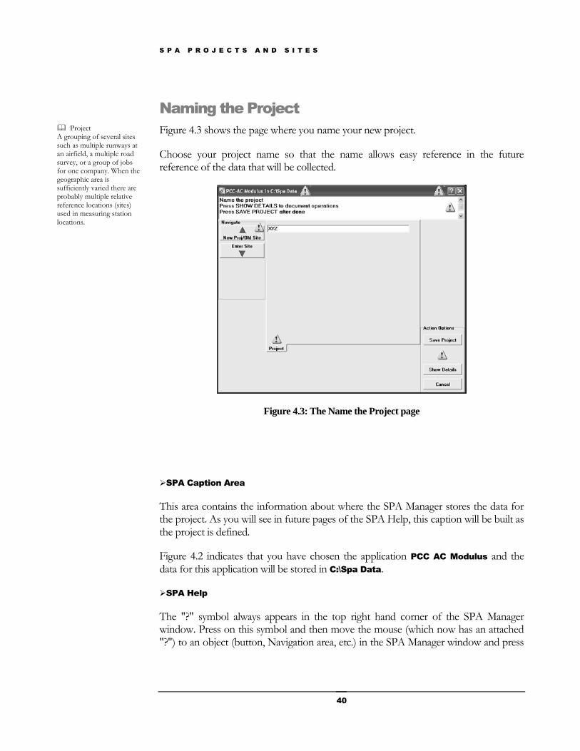
Naming the Project
Figure 4.3 shows the page where you name your new project.
Choose your project name so that the name allows easy reference in the future reference of the data that will be collected.
Figure 4.3: The Name the Project page
SPA Caption Area
This area contains the information about where the SPA Manager stores the data for the project. As you will see in future pages of the SPA Help, this caption will be built as the project is defined.
Figure 4.2 indicates that you have chosen the application PCC AC Modulus and the data for this application will be stored in C:\Spa Data.
SPA Help
The "?" symbol always appears in the top right hand corner of the SPA Manager window. Press on this symbol and then move the mouse (which now has an attached "?") to an object (button, Navigation area, etc.) in the SPA Manager window and press
Project A grouping of several sites such as multiple runways at an airfield, a multiple road survey, or a group of jobs for one company. When the geographic area is sufficiently varied there are probably multiple relative reference locations (sites) used in measuring station locations.
S P A P R O J E C T S A N D S I T E S
41
on the object. The portion of SPA Help for that object and page will be opened in separate window. Read the information and when finished, close the Help window.
SPA Guidance Area
The detailed instructions for this page are:
1. Name the project by typing your choice in the SPA Input area.
2. Press the Show Details button in the Action Options area and fill in necessary information.
3. Finally click the Save Project button in the Action Options area. This allows the SPA Manager to save your name and create a folder structure for your data.
SPA Navigate Area
Up arrow: Returns you to the previous screen (Select New Application Screen) to make corrections.
Down arrow: Continue to the "name the Site" screen.
SPA Input Area
project tab: Create the "Project" name. Note that the tab caption reflects that this is where project name is created.
SPA Manager supplies a default name which will be the same name as the "application" name. You may type in a more appropriate name for your new project when actually running SPA.
We have chosen XYZ as project name for this manual.
SPA Action Option Area
Save Project: The project name you selected is stored for subsequent action.
Show Details: Shows details of this particular project and add further information.
Cancel Button: Click this button to go to a page where you can either start over or quit the SPA Manager program.

S P A P R O J E C T S A N D S I T E S
42
Project Details
This page allows you to fill in further (optional) details about your new project. Put in any information you think is necessary for future reference. You are not limited to Operator, District and Phone.
Figure 4.4: Project Details page
SPA Caption Area
This area contains the information about where the SPA Manager stores the data for the project. As you will see in future pages of the SPA Help, this caption will be built as the project is defined.
Figure 4.2 indicates that you have chosen the application PCC AC Modulus and the data for this application will be stored in C:\Spa Data.
SPA Help
The "?" symbol always appears in the top right hand corner of the SPA Manager window. Press on this symbol and then move the mouse (which now has an attached "?") to an object (button, Navigation area, etc.) in the SPA Manager window and press on the object. The portion of SPA Help for that object and page will be opened in separate window. Read the information and when finished, close the Help window.
SPA Guidance Area
S P A P R O J E C T S A N D S I T E S
43
On this page you can add optional information about the project. When finished press the Save Project button in the Action Options area.
SPA Navigate Area
Up arrow: Returns you to the previous screen (Select New Application Screen) to make corrections.
Down arrow: Continue to the "Name the Site" screen.
SPA Input Area
1. Enter the name of the operator for this project.
2. Enter the district name.
3. Enter a telephone number.
4. Enter any further information that you think necessary for future reference.
SPA Action Options Area
Save Project: The project name you selected is stored for subsequent action.
Show Details: Shows details of this particular project.
Cancel Button: Click this button to go to a page where you can either start over or quit the SPA Manager program.
S P A P R O J E C T S A N D S I T E S
44
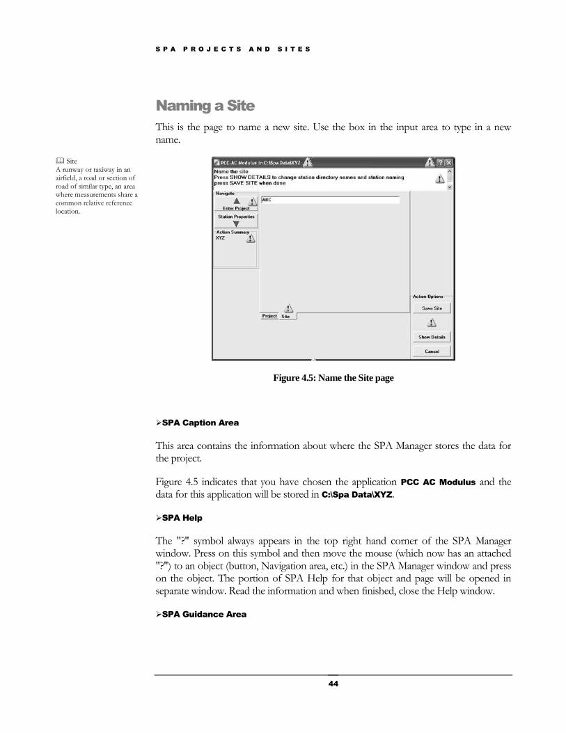
Naming a Site
This is the page to name a new site. Use the box in the input area to type in a new name.
Figure 4.5: Name the Site page
SPA Caption Area
This area contains the information about where the SPA Manager stores the data for the project.
Figure 4.5 indicates that you have chosen the application PCC AC Modulus and the data for this application will be stored in C:\Spa Data\XYZ.
SPA Help
The "?" symbol always appears in the top right hand corner of the SPA Manager window. Press on this symbol and then move the mouse (which now has an attached "?") to an object (button, Navigation area, etc.) in the SPA Manager window and press on the object. The portion of SPA Help for that object and page will be opened in separate window. Read the information and when finished, close the Help window.
SPA Guidance Area
Site A runway or taxiway in an airfield, a road or section of road of similar type, an area where measurements share a common relative reference location.
S P A P R O J E C T S A N D S I T E S
45
Here you choose a name for your site using the SPA input area.
Type the site name in the SPA input area then
1. Press the Show Details button in the Action Options area to add details for this particular site.
2. When finished, click the Save Site button in the Action Options area to save this information.
SPA Navigate Area
Up arrow: return to "Name the Project" screen.
Down arrow: Continue forward to the "Station" screen to collect data.
SPA Action Summary Area
New Area: This area will show the result of actions you have taken so far. In this case, it lists the name of the project, "XYZ”, which you made on the previous screen.
SPA Input Area
Site Tab: SPA Manager automatically supplies a site name of "default". You may enter a better (for your purposes) site name here. For this tutorial we erased "default" and typed in "A" for the new site name.
Note that this is the second tab.
If you click on the "Project" tab you see input area where you named the project.
SPA Action Options Area
Save Site: SPA saves the site name and optional information and creates a folder structure on the hard disk to store information from this site.
Show Details: Create details about the site. Both buttons are active in tutorial.
Cancel Button: Click this button to go to a page where you can either start over or quit the SPA Manager program.
S P A P R O J E C T S A N D S I T E S
46
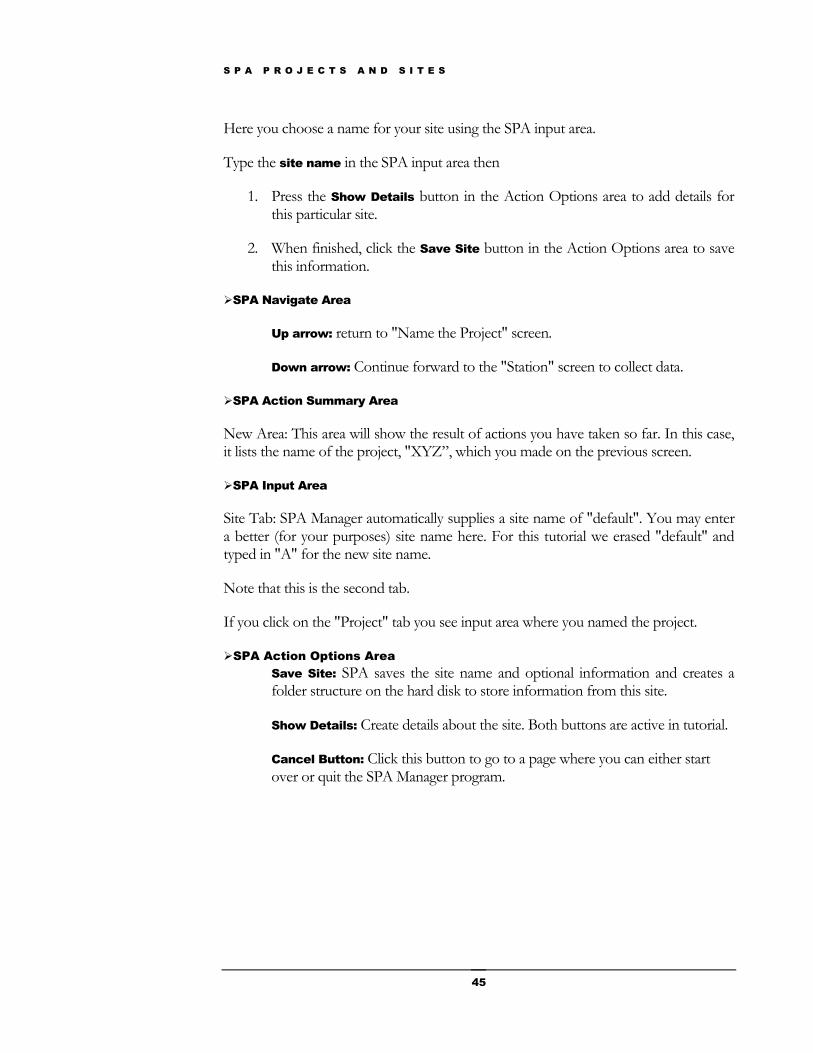
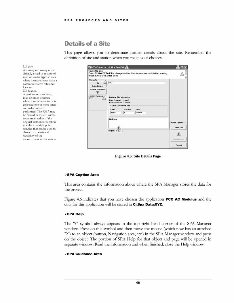
Details of a Site
This page allows you to determine further details about the site. Remember the definition of site and station when you make your choices.
Figure 4.6: Site Details Page
SPA Caption Area
This area contains the information about where the SPA Manager stores the data for the project.
Figure 4.6 indicates that you have chosen the application PCC AC Modulus and the data for this application will be stored in C:\Spa Data\XYZ.
SPA Help
The "?" symbol always appears in the top right hand corner of the SPA Manager window. Press on this symbol and then move the mouse (which now has an attached "?") to an object (button, Navigation area, etc.) in the SPA Manager window and press on the object. The portion of SPA Help for that object and page will be opened in separate window. Read the information and when finished, close the Help window.
SPA Guidance Area
Site A runway or taxiway in an airfield, a road or section of road of similar type, an area where measurements share a common relative reference location.
Station A position on a runway, road or other structure where a set of waveforms is collected one or more times and reductions are performed. The PSPA may be moved or rotated within some small radius of the original instrument location to collect multiple point samples that can be used to characterize statistical variability of the measurement at that station.

S P A P R O J E C T S A N D S I T E S
47
On this page you enter further details about the site:
1. Enter the prefix and suffix for naming the stations in this site and then
2. Enter the number of the first station.
3. Add a comment about this site. This comment will become a permanent part of the information for each station in this site.
When finished, click the Save Site button in the Action Options area to save this information.
SPA Navigate Area
Up arrow: return to "Name the Project" screen.
Down arrow: Continue forward to the "Station" screen to collect data.
SPA Action Summary Area
New Area: This area will show the result of actions you have taken so far. In this case, it lists the name of the project, "XYZ”, which you made on the previous page.
SPA Input Area
To change the default prefix, enter your prefix for stations at this site.
To change the default suffix, enter your suffix for stations at this site.
Enter the number of the first station. To change the default start number enter your number for the first station at this site. The first station at this site will be called "ABZY00001.P023S".
Add a site memo. This comment will become a permanent part of the information for each station in this site.
Remember that the prefix and suffix cannot contain the characters \, /, :, ?, <, >, or |.
If you press the "Project" tab you see input area where you named the project.
SPA Action Options Area

S P A P R O J E C T S A N D S I T E S
48
Save Site: SPA saves the site name and creates a directory structure on the hard disk to store information from this site.
Show Details: Create details about the site. Both buttons are active in tutorial.
Cancel Button: Click this button to go to a page where you can either start over or quit the SPA Manager program.
Having completed the project and site setup you are now ready to collect data at a station.
S P A S T A T I O N S
49
SPA Stations
How to setup and collect data at a Project -> Site -> Station
Introduction
The SPA Manager allows two workflows for stations (data collection/reduction ). There are several pages associated with each mode of operation. The pages are listed below and detailed further on in this chapter.
Chapter
5
Field Mode The data collection mode in which the PSPA is turned on and connected to the computer. This mode is designed to collect, reduce, analyze (when available) and create a report on data while in the field. Office Mode A mode where the PSPA is not connected to the computer. This mode is designed to (re)reduce, analyze (when available) and create a report on data previously collected in the field.
S P A S T A T I O N S
50
Field Mode Pages
Start a "New Station" page Definition: Station - A position on a runway, road or other structure where a set of waveforms is collected one or more times and reductions are performed. The PSPA may be moved or rotated within some small radius of the original instrument location to collect multiple point samples that can be used to characterize statistical variability of the measurement at that station.
"Collect a New" Sample waveforms for this Station page Definition: Sample - One group of waveforms collected by a "Collect New" action during SPA Manager data acquisition.
"Accept or Reject" the new waveforms of this sample Definition: Waveforms - A time record of the ground vibrations initiated by the PSPA source. The start time of the waveform corresponds to the firing of the PSPA source. The SPA Manager will record shorter time intervals for stiffer materials.
Reduced data page Definition: Reduction - A SPA Manager process in which waveforms are converted into a form that can be processed by the SPA Manager for one of the methods implemented in the SPA Manager. Examples of the methods include the Ultrasonic Surface Waves (USW) and Impact Echo (IE) tests.
Report page Definition: Report - A SPA Manager structured summary of selected results for one or more stations or samples.
On this page you can take previously collected data from one or more stations (during the field mode) and report the results.
Report Setup page Choose the type of report for your SPA data.
S P A S T A T I O N S
51
Office Mode Pages
(Re)Reduction page Definition: Reduction - A SPA Manager process in which waveforms are converted into a form that can be processed by the SPA Manager for one of the methods implemented in the SPA Manager. Examples of the methods include the Ultrasonic Surface Waves (USW) and Impact Echo (IE) tests.
On this page you can take previously collected data from one or more stations (during the field mode) and reduce the data again.
Report page Definition: Report - A SPA Manager structured summary of selected results for one or more stations or samples.
On this page you can take previously collected data from one or more stations (during the field mode) and report the results.
Setup Report page
On this page you decide on the appropriate format for your report.
The following pages will present the explanation of the Office mode and Field mode pages.
S P A S T A T I O N S
52
Field Mode: Creating a New Station
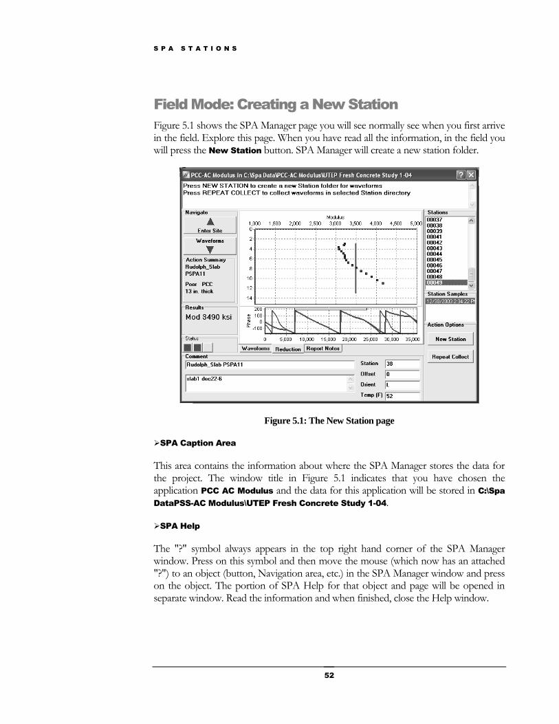
Figure 5.1 shows the SPA Manager page you will see normally see when you first arrive in the field. Explore this page. When you have read all the information, in the field you will press the New Station button. SPA Manager will create a new station folder.
Figure 5.1: The New Station page
SPA Caption Area
This area contains the information about where the SPA Manager stores the data for the project. The window title in Figure 5.1 indicates that you have chosen the application PCC AC Modulus and the data for this application will be stored in C:\Spa
DataPSS-AC Modulus\UTEP Fresh Concrete Study 1-04.
SPA Help
The "?" symbol always appears in the top right hand corner of the SPA Manager window. Press on this symbol and then move the mouse (which now has an attached "?") to an object (button, Navigation area, etc.) in the SPA Manager window and press on the object. The portion of SPA Help for that object and page will be opened in separate window. Read the information and when finished, close the Help window.
S P A S T A T I O N S
53
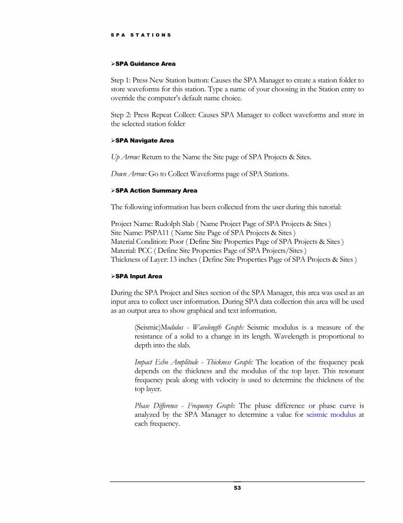
SPA Guidance Area
Step 1: Press New Station button: Causes the SPA Manager to create a station folder to store waveforms for this station. Type a name of your choosing in the Station entry to override the computer’s default name choice.
Step 2: Press Repeat Collect: Causes SPA Manager to collect waveforms and store in the selected station folder
SPA Navigate Area
Up Arrow: Return to the Name the Site page of SPA Projects & Sites.
Down Arrow: Go to Collect Waveforms page of SPA Stations.
SPA Action Summary Area
The following information has been collected from the user during this tutorial:
Project Name: Rudolph Slab ( Name Project Page of SPA Projects & Sites ) Site Name: PSPA11 ( Name Site Page of SPA Projects & Sites ) Material Condition: Poor ( Define Site Properties Page of SPA Projects & Sites ) Material: PCC ( Define Site Properties Page of SPA Projects/Sites ) Thickness of Layer: 13 inches ( Define Site Properties Page of SPA Projects & Sites )
SPA Input Area
During the SPA Project and Sites section of the SPA Manager, this area was used as an input area to collect user information. During SPA data collection this area will be used as an output area to show graphical and text information.
(Seismic)Modulus - Wavelength Graph: Seismic modulus is a measure of the resistance of a solid to a change in its length. Wavelength is proportional to depth into the slab.
Impact Echo Amplitude - Thickness Graph: The location of the frequency peak depends on the thickness and the modulus of the top layer. This resonant frequency peak along with velocity is used to determine the thickness of the top layer.
Phase Difference - Frequency Graph: The phase difference or phase curve is analyzed by the SPA Manager to determine a value for seismic modulus at each frequency.
S P A S T A T I O N S
54
SPA Stations Area
Station (Point) Samples: All groups of waveforms collected by a "Repeat Collect" action during SPA Manager data acquisition at the chosen station in the above "Stations" panel.
SPA Station Samples Area
This panel displays all of the samples at the station chosen in the Stations panel above. In the example, no station was chosen so no samples were displayed in the Samples panel.
SPA Action Summary Area
The following information has been collected from the user during this tutorial:
Project Name: Rudolph Slab ( Name Project Page of SPA Projects & Sites ) Site Name: PSPA11 ( Name Site Page of SPA Projects & Sites ) Material Condition: Poor ( Define Site Properties Page of SPA Projects & Sites ) Material: PCC ( Define Site Properties Page of SPA Projects/Sites ) Thickness of Layer: 13 inches ( Define Site Properties Page of SPA Projects & Sites )
PSPA Status Area
This panel may show up to five status lights, depending on the context. The leftmost light indicates the battery/power supply condition. If using a PSPA-P under battery power, the light has the following meanings..
Green: More than 500 stations can be collected without recharging.
Yellow: Between 50 and 500 stations can be collected without recharging.
Red: Less than 50 stations can be collected without recharging.
In this example, station 49 has agreen indicator, and the cursor flyover would show an estimate of the number of remaining samples.
In base and subgrade testing, additional status lights may be shown, in this case two others. The second light from the left indicates a computer estimate of the receiver/source coupling to the ground. The cursor flyover will give the coupling status, and suggest which sensor has problems if the light is not green. The third status light attempts to give an indication of interpretation quality. On bases and subgrades, a non-green light indicates that the waveforms can not be interpreted using SASW analysis techniques, and a lesser-quality interpretation has been made.
SPA Comments Area
Stations: A list of all stations from the present site where SPA data were collected.

S P A S T A T I O N S
55
Static Comment: A comment that is stored in the folder of all stations for a particular site. The SPA Manager will automatically create a comment based on the project and site names. You may change this to a more appropriate comment.
Dynamic Comment: A user supplied comment that is made for an individual station. The comment is at the user's discretion. The comment could relate to environmental or material conditions.
Station: The "name" for this station. The name can be numerical or composed of letters or both. Numerical names will automatically be incremented by the whenever a "New Station" is created.
Offset: The offset or distance of the SPA from a geographic feature such as the edge of the road or runway.
Orientation: The orientation of the PSPA. This could be with respect to north & south, or could be defined as parallel or perpendicular to a geographic feature like a road or runway.
Temp (F): A small temperature sensor is located on the underside of the PSPA source. This sensor measures the temperature of the material under the source and the result is shown here.
SPA Action Options Area
New Station: Causes a new folder to be created to store the data of a new station.
Repeat Collection: Causes the SPA Manager to activate the PSPA source and collect a new set of waveforms.
S P A S T A T I O N S
56
Field Mode: Collecting New Waveforms
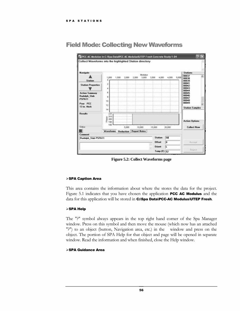
Figure 5.2: Collect Waveforms page
SPA Caption Area
This area contains the information about where the stores the data for the project. Figure 5.1 indicates that you have chosen the application PCC AC Modulus and the data for this application will be stored in C:\Spa Data\PCC-AC Modulus\UTEP Fresh.
SPA Help
The "?" symbol always appears in the top right hand corner of the Spa Manager window. Press on this symbol and then move the mouse (which now has an attached "?") to an object (button, Navigation area, etc.) in the window and press on the object. The portion of SPA Help for that object and page will be opened in separate window. Read the information and when finished, close the Help window.
SPA Guidance Area
S P A S T A T I O N S
57
Step 1: Press New Station button: Causes the Spa Manager to create a station folder to store waveforms for this station. You may type over the computer’s suggested station name before waveform collection.
Step 2: Press Repeat Collect: Causes the Spa Manager to collect waveforms and store in the selected station folder
SPA Navigate Area
Up Arrow: Return to the Name the Site page of SPA Projects & Sites.
Down Arrow: Go to Collect Waveforms page of SPA Stations.
SPA Action Summary Area
The following information has been collected from the user during this tutorial:
Project Name: Rudolph Slab ( Name Project Page of SPA Projects & Sites ) Site Name: PSPA11 ( Name Site Page of SPA Projects & Sites ) Material Condition: Poor ( Define Site Properties Page of SPA Projects & Sites ) Material: PCC ( Define Site Properties Page of SPA Projects/Sites ) Thickness of Layer: 13 inches ( Define Site Properties Page of SPA Projects & Sites )
SPA Input Area
During the SPA Project and Sites section of the Spa Manager, this area was used as an input area to collect user information. During SPA data collection this area will be used as an output area to show graphical and text information.
(Seismic)Modulus - Wavelength Graph: Seismic modulus is a measure of the resistance of a solid to a change in its length. Wavelength is proportional to depth into the slab.
Impact Echo Amplitude - Thickness Graph: The location of the frequency peak depends on the thickness and the modulus of the top layer. This resonant frequency peak along with velocity is used to determine the thickness of the top layer. This graph is displayed in the PCC Quality Application
Phase Difference - Frequency Graph: The phase difference or phase curve is analyzed by the SPA Manager to determine a value for seismic modulus at each frequency.
SPA Stations Area Stations: A list of all stations from the present site where SPA data were collected.

S P A S T A T I O N S
58
Station (Point) Samples: All groups of waveforms collected by a "Repeat Collect" action during SPA Manager data acquisition at the chosen station in the above "Stations" panel.
SPA Station Samples Area
This panel displays all of the samples at the station chosen in the Stations panel above. In the example, no station was chosen so no samples were displayed in the Samples panel.
SPA Action Summary Area
The following information has been collected from the user during this tutorial:
Project Name: Rudolph Slab ( Name Project Page of SPA Projects & Sites ) Site Name: PSPA11 ( Name Site Page of SPA Projects & Sites ) Material Condition: Poor ( Define Site Properties Page of SPA Projects & Sites ) Material: PCC ( Define Site Properties Page of SPA Projects/Sites ) Thickness of Layer: 13 inches ( Define Site Properties Page of SPA Projects & Sites )
SPA Status Area
This panel may show up to five status lights, depending on the context. The leftmost light indicates the battery/power supply condition. If using a PSPA-P under battery power, the light has the following meanings..
Green: More than 500 stations can be collected without recharging.
Yellow: Between 50 and 500 stations can be collected without recharging.
Red: Less than 50 stations can be collected without recharging.
In this example, the new station 50 has a red indicator, indicating .an unknown status for the USB hardware for this station.
SPA Comments Area
S P A S T A T I O N S
59
Static Comment: A comment that is stored in the folder of all stations for a particular site. The Spa Manager will automatically create a comment based on the project and site names. You may change this to a more appropriate comment.
Dynamic Comment: A user supplied comment that is made for an individual station. The comment is at the user's discretion. The comment could relate to environmental or material conditions.
Station: The "name" for this station. The name can be numerical or composed of letters or both. Numerical names will automatically be incremented by the Spa Manager whenever a "New Station" is created.
Offset: The offset or distance of the PSPA from a geographic feature such as the edge of the road or runway.
Orientation: The orientation of the PSPA. This could be with respect to north & south, or could be defined as parallel or perpendicular to a geographic feature like a road or runway.
Temp (F): A small temperature sensor is located on the underside of the PSPA source. This sensor measures the temperature of the material under the source and the result is shown here.
SPA Action Options Area
New Station: Causes a new folder to be created to store the data of a new station.
Repeat Collection: Causes the Spa Manager to activate the PSPA source and collect a new set of waveforms
S P A S T A T I O N S
60
Field Mode: Accepting / Rejecting a SPA Waveform
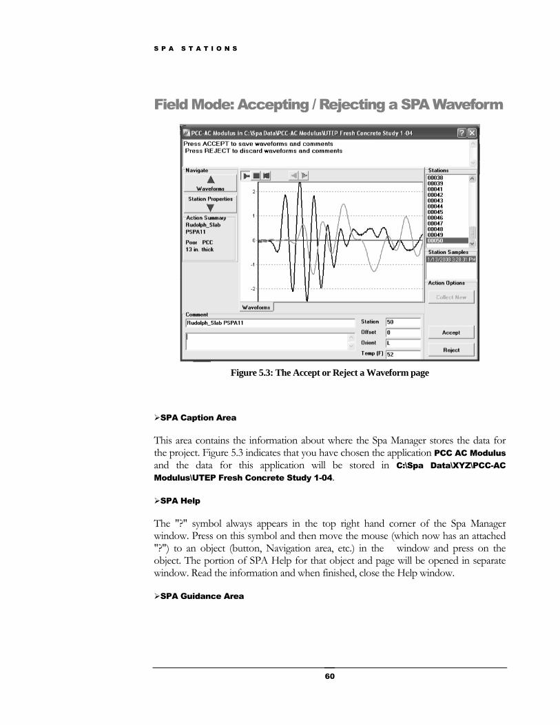
Figure 5.3: The Accept or Reject a Waveform page
SPA Caption Area
This area contains the information about where the Spa Manager stores the data for the project. Figure 5.3 indicates that you have chosen the application PCC AC Modulus and the data for this application will be stored in C:\Spa Data\XYZ\PCC-AC
Modulus\UTEP Fresh Concrete Study 1-04.
SPA Help
The "?" symbol always appears in the top right hand corner of the Spa Manager window. Press on this symbol and then move the mouse (which now has an attached "?") to an object (button, Navigation area, etc.) in the window and press on the object. The portion of SPA Help for that object and page will be opened in separate window. Read the information and when finished, close the Help window.
SPA Guidance Area
S P A S T A T I O N S
61
Step 1: Press ACCEPT: Causes the Spa Manager to reduce these waveforms and show the results of the reduction on the next page and save the waveforms.
Step 2: Press REJECT: Causes the Spa Manager to destroy these waveforms and allow you to collect a new set of waveforms.
SPA Navigate Area
Up Arrow: Return to the Name the Site page of SPA Projects & Sites.
Down Arrow: Go to Collect Waveforms page of SPA Stations.
SPA Action Summary Area
The following information has been collected from the user during this tutorial:
Project Name: Rudolph Slab ( Name Project Page of SPA Projects & Sites ) Site Name: PSPA11 ( Name Site Page of SPA Projects & Sites ) Material Condition: Poor ( Define Site Properties Page of SPA Projects & Sites ) Material: PCC ( Define Site Properties Page of SPA Projects/Sites ) Thickness of Layer: 13 inches ( Define Site Properties Page of SPA Projects & Sites )
SPA Input Area
During the SPA Project and Sites section of the Spa Manager, this area was used as an input area to collect user information and display area. On this page, the waveform collected by the PSPA is shown.
SPA Stations Area
Station (Point) Samples: All groups of waveforms collected by a "Repeat Collect" action during the SPA Manager data acquisition at the chosen station in the above "Stations" panel.
SPA Station Samples Area
This panel displays all of the samples at the station chosen in the Stations panel above. In the example, no station was chosen so no samples were displayed in the Samples panel.
SPA Action Summary Area
The following information has been collected from the user during this tutorial:
Project Name: Rudolph Slab ( Name Project Page of SPA Projects & Sites ) Site Name: PSPA11 ( Name Site Page of SPA Projects & Sites ) Material Condition: Poor ( Define Site Properties Page of SPA Projects & Sites )
Stations: A list of all stations from the present site where SPA data were collected.
S P A S T A T I O N S
62
Material: PCC ( Define Site Properties Page of SPA Projects/Sites ) Thickness of Layer: 13 inches ( Define Site Properties Page of SPA Projects & Sites )
SPA Battery Area
This panel indicates the number of stations that can be collected under normal circumstances without recharging the PSPA batteries. There are three levels.
Green: More than 500 stations can be collected without recharging.
Yellow: Between 50 and 500 stations can be collected without recharging.
Red: Less than 50 stations can be collected without recharging.
In this example, no color is shown because no station data has been accepted. The battery condition is related to a particular station sample after the waveforms have been reduced..
SPA Comments Area
Static Comment: A comment that is stored in the folder of all stations for a particular site. The Spa Manager will automatically create a comment based on the project and site names. You may change this to a more appropriate comment.
Dynamic Comment: A user supplied comment that is made for an individual station. The comment is at the user's discretion. The comment could relate to environmental or material conditions.
Station: The "name" for this station. The name can be numerical or composed of letters or both. Numerical names will automatically be incremented by the Spa Manager whenever a "New Station" is created.
Offset: The offset or distance of the PSPA from a geographic feature such as the edge of the road or runway.
Orientation: The orientation of the PSPA. This could be with respect to north & south, or could be defined as parallel or perpendicular to a geographic feature like a road or runway.
Temp (F): A small temperature sensor is located on the underside of the PSPA source. This sensor measures the temperature of the material under the source and the result is shown here.
SPA Action Options Area
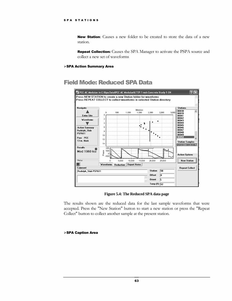
S P A S T A T I O N S
63
New Station: Causes a new folder to be created to store the data of a new station.
Repeat Collection: Causes the SPA Manager to activate the PSPA source and collect a new set of waveforms
SPA Action Summary Area
Field Mode: Reduced SPA Data
Figure 5.4: The Reduced SPA data page
The results shown are the reduced data for the last sample waveforms that were accepted. Press the "New Station" button to start a new station or press the "Repeat Collect" button to collect another sample at the present station.
SPA Caption Area
S P A S T A T I O N S
64
This area contains the information about where the Spa Manager stores the data for the project. Figure 5.4 indicates that you have chosen the application PCC AC Modulus and the data for this application will be stored in C:\Spa Data\PCC-AC Modulus\UTEP
Fresh Concrete Study 1-04.
SPA Help
The "?" symbol always appears in the top right hand corner of the Spa Manager window. Press on this symbol and then move the mouse (which now has an attached "?") to an object (button, Navigation area, etc.) in the window and press on the object. The portion of SPA Help for that object and page will be opened in separate window. Read the information and when finished, close the Help window.
SPA Guidance Area
Step 1: Press New Station button: Causes the Spa Manager to create a station folder to store waveforms for this station.
Step 2: Press Repeat Collect: Causes the Spa Manager to collect waveforms and store in the selected station folder
SPA Navigate Area
SPA Action Summary Area
The following information has been collected from the user in our example:
Project Name: Rudolph Slab ( Name Project Page of SPA Projects & Sites ) Site Name: PSPA11 ( Name Site Page of SPA Projects & Sites ) Material Condition: Poor ( Define Site Properties Page of SPA Projects & Sites ) Material: PCC ( Define Site Properties Page of SPA Projects/Sites ) Thickness of Layer: 13 inches ( Define Site Properties Page of SPA Projects & Sites )
SPA Results Area
Results from SPA data collection and reduction are shown here. For this application, since the station chosen has not been reduced because this waveform has not yet been accepted, there are no results yet.
SPA Input Area
S P A S T A T I O N S
65
During the SPA Project and Sites section of the Spa Manager, this area was used as an input area to collect user information. During SPA data collection this area will be used as an output area to show graphical and text information.
The (seismic) Modulus - Wavelength Graph: Seismic modulus is a measure of the resistance of a solid to a change in its length. Wavelength is proportional to depth into the slab.
Impact Echo Amplitude - Thickness Graph: The location of the frequency peak depends on the thickness and the modulus of the top layer. This resonant frequency peak along with velocity is used to determine the thickness of the top layer.
Phase Difference - Frequency Graph: The phase difference or phase curve is analyzed by the Spa Manager to determine a value for seismic modulus at each frequency.
SPA Stations Area
A list of all stations at the present site.
SPA Station Samples Area
This panel displays all of the samples at the station chosen in the Stations panel. In the example, station 13 was chosen and all samples from station 13 are displayed in the Station Samples panel.
PSPA Battery Area
This panel indicates the number of stations that can be collected under normal circumstances without recharging the PSPA batteries. There are three levels.
Green: More than 500 stations can be collected without recharging.
Yellow: Between 50 and 500 stations can be collected without recharging.
Red: Less than 50 stations can be collected without recharging.
SPA Comments Area
S P A S T A T I O N S
66
Static Comment: A comment that is stored in the folder of all stations for a particular site. The SPA Manager will automatically create a comment based on the project and site names. You may change this automatic comment.
Dynamic Comment: A user supplied comment that is made for an individual station. The comment is at the user's discretion. The comment could relate to environmental or material conditions.
SPA Action Options Area
New Station: Causes the Spa Manager to create a new station and takes you to the data collection page.

S P A S T A T I O N S
67
Office Mode: Reduced SPA Data
Figure 5.5 shows the first page you see when you are in Office Mode.
Figure 5.5: The Reduced SPA data page
Select a single station and press the reduce button to reduce just one station. Select where in the list of stations (of this project) for this site (shown in the stations area) you wish to start reducing the data and press "Start List". This will cause the Spa Manager to reduce the data from all of the stations following the selection.
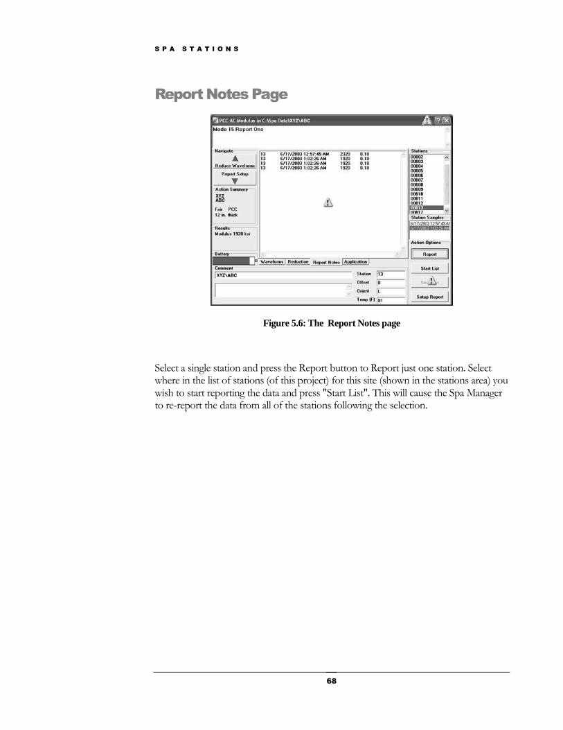
S P A S T A T I O N S
68
Report Notes Page
Figure 5.6: The Report Notes page
Select a single station and press the Report button to Report just one station. Select where in the list of stations (of this project) for this site (shown in the stations area) you wish to start reporting the data and press "Start List". This will cause the Spa Manager to re-report the data from all of the stations following the selection.
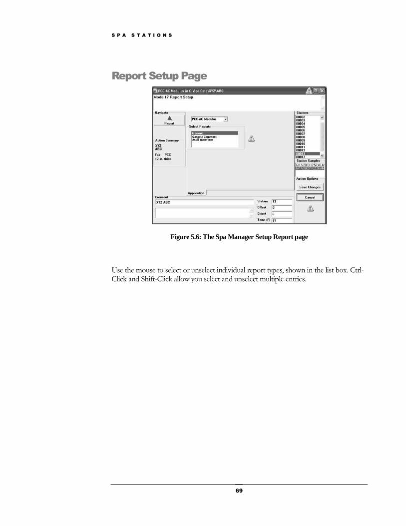
S P A S T A T I O N S
69
Report Setup Page
Figure 5.6: The Spa Manager Setup Report page
Use the mouse to select or unselect individual report types, shown in the list box. Ctrl-Click and Shift-Click allow you select and unselect multiple entries.
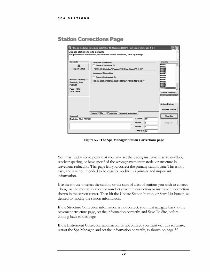
S P A S T A T I O N S
70
Station Corrections Page
Figure 5.7: The Spa Manager Station Corrections page
You may find at some point that you have set the wrong instrument serial number, receiver spacing, or have specified the wrong pavement material or structure in waveform reduction. This page lets you correct the primary station data. This is not easy, and it is not intended to be easy to modify this primary and important information.
Use the mouse to select the station, or the start of a list of stations you wish to correct. Then, use the mouse to select or unselect structure correction or instrument correction shown in the screen center. Then hit the Update Station button, or Start List button, as desired to modify the station information.
If the Structure Correction information is not correct, you must navigate back to the pavement structure page, set the information correctly, and Save To Site, before coming back to this page.
If the Instrument Correction information is not correct, you must exit this software, restart the Spa Manager, and set the information correctly, as shown on page 32.
M A I N T A I N I N G T H E S P A
71
Maintaining the SPA
Preventive maintenance for the PSPA and the
Maintaining the PSPA-P Batteries
There are four battery options for the PSPA:
1. The PSPA is initially supplied with 10 NiMH AA batteries.
2. In a pinch, 10 AA NiCad batteries will power the unit for over a day of routine collection.
3. Disposable alkaline AA batteries can also be used. We expect these will provide approximately four days of routine data collection.
4. Finally, the internal batteries may be discarded, and run the PSPA from an external 12 to 18 volt power source capable of supplying 400 ma of current (battery, solar, or power line).
Chapter
6
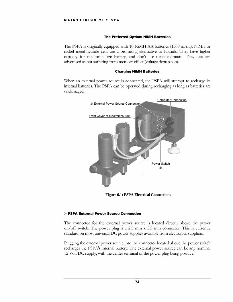
M A I N T A I N I N G T H E S P A
72
The Preferred Option: NiMH Batteries
The PSPA is originally equipped with 10 NiMH AA batteries (1500 mAH). NiMH or nickel metal-hydride cells are a promising alternative to NiCads. They have higher capacity for the same size battery, and don't use toxic cadmium. They also are advertised as not suffering from memory effect (voltage depression).
Charging NiMH Batteries
When an external power source is connected, the PSPA will attempt to recharge its internal batteries. The PSPA can be operated during recharging as long as batteries are undamaged.
. Figure 6.1: PSPA Electrical Connections
PSPA External Power Source Connection
The connector for the external power source is located directly above the power on/off switch. The power plug is a 2.5 mm x 5.5 mm connector. This is currently standard on most universal DC power supplies available from electronics suppliers.
Plugging the external power source into the connector located above the power switch recharges the PSPA's internal battery. The external power source can be any nominal 12 Volt DC supply, with the center terminal of the power plug being positive.
M A I N T A I N I N G T H E S P A
73
The external power source (AC line recharger) supplied with the PSPA is a 500 mA, 12 volt, unregulated, Radio Shack wall cube. The external power source can be any nominal 12 Volt DC supply, with the center terminal of the power plug being positive.
The PSPA has an internal battery recharger located inside the electronics box which uses a simple current limiting circuit. This circuit has a jumper to select recharging currents for either NiMH (see other options below) or NiCad batteries. AA NiMH batteries are generally 1500 mAH batteries recharged at 150 mA.
Normal daily use operation of the PSPA must include recharging by the AC line power supply at night. The batteries will generally run several days of routine data collection of two hundred stations per day on a single full charge.
The external power source that comes with the PSPA is a 500 mA, 12 volt, unregulated, Radio Shack wall cube. The normal output voltage of the output cube at low current draw can be as high as 15 volts, and this will recharge the NiMH battery pack to over 13 volts in eight hours of charging overnight. We do not recommend leaving the AC line supply plugged in recharging the batteries for more than 15 hours, as the batteries may become damaged. Use of a higher current capacity recharger (1 or 1.5 amp) will permit faster battery recharging.

M A I N T A I N I N G T H E S P A
74
Using an Automobile to charge the PSPA Batteries
Another possible mode of operation would be to plug the PSPA into an automobile cigarette lighter outlet, either with or without the vehicle running.
The auto battery can recharge the PSPA batteries somewhat faster than the line charger, as quickly as 6 hours. If the vehicle is not running, the nominal lead-acid voltage of 13.6 volts will recharge the NiMH battery back to about 13 volts, and can be left on indefinitely, with no damage to the batteries. With the engine running, the time the PSPA should be connected should be less than 15 hours.
The remaining battery life in terms of the number of stations remaining will continuously be indicated in the Spa Manager’s battery area.
Accessing the Battery Pack
The battery pack is accessed by removing the six Phillips screws on the back cover of the electronics box and removing the cover, as shown in figure 6.2.
Figure 6.2: PSPA Battery location.
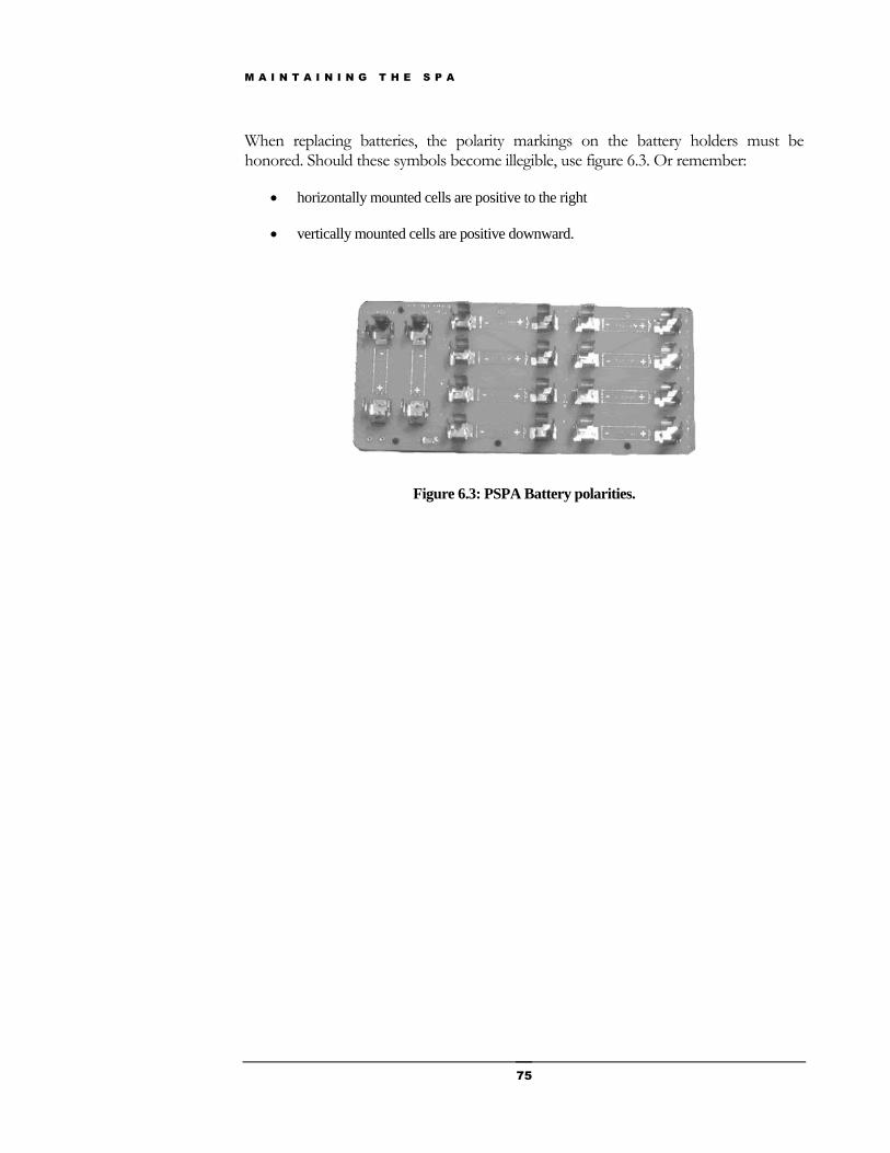
M A I N T A I N I N G T H E S P A
75
When replacing batteries, the polarity markings on the battery holders must be honored. Should these symbols become illegible, use figure 6.3. Or remember:
horizontally mounted cells are positive to the right
vertically mounted cells are positive downward.
Figure 6.3: PSPA Battery polarities.

M A I N T A I N I N G T H E S P A
76
Using NiCad AA Cells
If you choose to use internal NiCad AA cells, instead of the NiMH cells supplied with the PSPA, it is necessary to remove a jumper on the recharging circuit for the lower recharging current needed. This jumper is located on a circuit board mounted in the electronics box.
The circuit board is accessed by removing the six Phillips head screws from the front side of the electronics box (the side facing the PSPA source and receivers). The circuit board and jumper are shown below. Failure to remove this jumper with NiCad cells installed in the PSPA will shorten battery life, and may result in battery leakage due to overcharging if left on the recharger too long.
Figure 6.4: PSPA Circuit board and jumper.
Using Alkaline AA Cells
If you choose to use internal alkaline AA cells,
NEVER CONNECT AN EXTERNAL POWER SOURCE.
These batteries are not rechargeable and unnecessary battery pyrotechnics will probably require an expensive circuit board replacement.
PSPA Maintenance
Problem: Sticky Pistons. Clean the outside of the piston off. With a Q-tip, apply a small amount of the light bicycle-type lubricant around the piston near the seal. Remove the
M A I N T A I N I N G T H E S P A
77
top cylinder cap, and with the Q-tip, apply a little bit more lubricant around the inside of the cylinder, as deeply as you can reach. Work the piston by hand, and it should start to move freely. If this does not repair the problem, an experienced technician can remove the clip-ring and spring, and remove the piston for maintenance.
Maintaining the Spa Manager Software
The software comes installed on the Panasonic Toughbook computer. If you did not purchase this computer or some egregious event has happened which destroyed the software on you computer, the software can be reinstalled using the following instructions.
1. Insert the CD into the CD drive of your computer (e.g., D: )
2. Create a directory C:\SpaDoc\SpaMgr Installation V3.2.27
3. Copy the setup files from the deepest directory of the CD into this directory.
4. Execute Setup.exe from the directory on C:\
5. Create a shortcut on the desktop to C:\Program Files\OptionsSetup.exe named SpaMgr .
6. Copy the shortcut into C:\Documents and Settings\All Users\Start Menus\Startup .
7. Close the above window.
8. Move to C:\Program Files\GrdSpaV3.2 .
9. Execute SpaHelpDoc.exe. Enter C:\ for the install directory. Execute the unzip.
10. Check the directory C:\SpaDoc directory for the presence of files.
11. Execute C:\SpaDoc\SpaTutorial.exe to insure that it functions.
12. Execute C:\Program Files\GrdSpaV3.2\BoardTest.exe Click on the “Open Port” button. You should see the following message in the bottom bar: “Reboot and try again. Port reconfigured.” Exit BoardTest.exe
M A I N T A I N I N G T H E S P A
78
13. Restart your computer
14. Connect the parallel port ( DB 25) cable to the PSPA
15. Turn on the PSPA power switch The SPA Manager option setup page should appear. Execute the self test.
16. Press the “Start Self Test” button if you did not get the PSPA turned on in time. Make sure that the SPSA batteries are charged and the PSPA is turned on.
17. Press on the “Instrument” tab showing on the SPA Manager window.
18. Select the correct hardware. Make sure that the source and receiver serial numbers and spacings are the same as your PSPA. If not, make the appropriate changes to the instrument tab.
19. Save your changes.
20. Press the “Start Options” tab.
21. Press the “Start New Application” button.
22. Select the default Application, Project, Site.
23. Change “PCC Thickness” to 4”.
24. Save to the default directory.
25. Press the “New Station” button.
26. Ensure that “Help” starts at the correct page.
27. Press the “New Station” button.
28. Press the “Collect New” button.
29. Enter a comment then press the “Accept” button.
30. Ensure that the reduction is completed and check the Report “Notes tab” to insure that the data are recorded.
31. Exit the program.
32. (Optional) Copy a shortcut to the Spa Help to the desktop for learning purposes. This is actually an electronic version of this manual.

M A I N T A I N I N G T H E S P A
79
33. Remove the CD from the CD drive.
34. Turn off the PSPA when finished.
Please note that there is an additional source and version of the Spa Manager installed in C:\Spa Software\Install XP\... This is for the field situation where you have a failure of the SPA Manager while in the field and did not bring the CD with you into the field.

I N D E X
80
Index
B
Batteries
access, 71
charge, 58, 62, 65
location, 71
maintaining, 71-75
NiMH, 16, 71, 72
polarity, 75
F
Fourier Transforms, 6
G
Graph
impact echo, 52
modulus-wavelength, 52
Phase difference-frequency, 53
H
Help Symbol, 26
Hooke's law, 10
I
Impact Echo, 2, 5, 9, 52, 56, 63
M
Maintenance, 15, 71-76
Mode
Field mode, 23, 24,49
Office mode, 23, 49
Modulus
chord, 10
FWD, 10
Initial tangent, 10
resilient, 10
P
Phase difference, 8, 52, 56, 63
Power Switch, 13, 15
Properties
density, 34
materials, 33
modulus, 34
qualifier, 33
visual condition, 33
wave velocities, 34
PSPA
deploying, 21
hardware, 1, 3
R
Rails, 17, 18
Receiver, 3, 6, 8, 13, 16, 22, 27, 32, 75
Reduction, 1, 5, 28, 29, 30, 35, 46, 50, 78
Report, 11, 30, 31, 50, 66, 68,69
Notes page, 66
Setup page, 69
S
Seismic Modulus, 5, 6, 11, 36, 52-3, 57, 65
Serial number, 27-8, 32, 70
Source, 1-3, 13-14, 18, 22, 27, 32, 75
SPA Manager, 1, 2, 3, 11, 23
Station, 3, 46, 56, 60, 64
T
Temperature
sensor, 55, 62
U
Ultrasonic Surface Waves, 2, 5
User interface, 2

I N D E X
81
V
Vibrations, 3, 49
W
Waves
mechanical or stress, 9
P wave, 3
R wave, 4
S wave, 4