Genius lt J - Amazon Web Servicesassets.scott-sports.com.s3.amazonaws.com/.../2012_J_… · ·...
19
SCOTT 2012 BIKE OWNERS MANUAL GENIUS LT SCOTT SPORTS SA | 17 RTE DU CROCHET | 1762 GIVISIEZ | SWITZERLAND © 2011 SCOTT SPORTS SA, ALL RIGHTS RESERVED | SCOTT-SPORTS.COM J
-
Upload
vuongduong -
Category
Documents
-
view
217 -
download
1
Transcript of Genius lt J - Amazon Web Servicesassets.scott-sports.com.s3.amazonaws.com/.../2012_J_… · ·...

scott 2012bike ownersmanual
Genius lt
scott sPorts sa | 17 RTE DU CROCHET | 1762 GIVISIEZ | SWITZERLAND© 2011 SCOTT SPORTS SA, ALL RIGHTS RESERVED | SCOTT-SPORTS.COM J

2 scott-sports.com 3
Ge
niu
s LT
en
GLi
sh
BIKE OWNERS MANUAL
content
Genius LT Concept . . . . . . . . . . . . . . . . . . . . . . . . . . . . . . . . . . . . . . . . . . . . . . . . . . . . . . . . . . . . . P. 004
Geometry Genius LT . . . . . . . . . . . . . . . . . . . . . . . . . . . . . . . . . . . . . . . . . . . . . . . . . . . . . . . . . . . . P. 005
Technical Data Genius LT . . . . . . . . . . . . . . . . . . . . . . . . . . . . . . . . . . . . . . . . . . . . . . . . . . . . . . . P. 006
Geometry Chip . . . . . . . . . . . . . . . . . . . . . . . . . . . . . . . . . . . . . . . . . . . . . . . . . . . . . . . . . . . . . . . . . P. 007
TWINLOC Remote Control Lever . . . . . . . . . . . . . . . . . . . . . . . . . . . . . . . . . . . . . . . . . . . . . . . P. 008
Rear Shock Technology . . . . . . . . . . . . . . . . . . . . . . . . . . . . . . . . . . . . . . . . . . . . . . . . . . . . . . . . . . P. 012
Equalizer 3 Shock and TWINLOC Remote Control Lever . . . . . . . . . . . . . . . . . . . . . . . . . P. 013
Basic Set-Up of the TWINLOC Remote Control . . . . . . . . . . . . . . . . . . . . . . . . . . . . . . . . . .P. 014
Recommended Tools for the Shock Set-Up . . . . . . . . . . . . . . . . . . . . . . . . . . . . . . . . . . . . . .P. 018
Set-Up Genius LT with Equalizer 3 Shock . . . . . . . . . . . . . . . . . . . . . . . . . . . . . . . . . . . . . . . . .P. 019
Set-Up of Rebound Equalizer 3 Shock . . . . . . . . . . . . . . . . . . . . . . . . . . . . . . . . . . . . . . . . . . . P. 021
Set-Up of other Shock Models . . . . . . . . . . . . . . . . . . . . . . . . . . . . . . . . . . . . . . . . . . . . . . . . . . P. 024
BB Standards . . . . . . . . . . . . . . . . . . . . . . . . . . . . . . . . . . . . . . . . . . . . . . . . . . . . . . . . . . . . . . . . . . . P. 024
Front Derailleur Mounting Details . . . . . . . . . . . . . . . . . . . . . . . . . . . . . . . . . . . . . . . . . . . . . . . P. 025
Chainguide . . . . . . . . . . . . . . . . . . . . . . . . . . . . . . . . . . . . . . . . . . . . . . . . . . . . . . . . . . . . . . . . . . . . . P. 026
Headset Options . . . . . . . . . . . . . . . . . . . . . . . . . . . . . . . . . . . . . . . . . . . . . . . . . . . . . . . . . . . . . . . P. 028
Scott Smart Cable Routing . . . . . . . . . . . . . . . . . . . . . . . . . . . . . . . . . . . . . . . . . . . . . . . . . . . . . P. 029
Cable Housing Length . . . . . . . . . . . . . . . . . . . . . . . . . . . . . . . . . . . . . . . . . . . . . . . . . . . . . . . . . . P. 030
Adjustment of Seatpost Height . . . . . . . . . . . . . . . . . . . . . . . . . . . . . . . . . . . . . . . . . . . . . . . . . . P. 031
Rear Disc Brake Mount . . . . . . . . . . . . . . . . . . . . . . . . . . . . . . . . . . . . . . . . . . . . . . . . . . . . . . . . . . . P. 031
IDS 2 / Replaceable Dropout . . . . . . . . . . . . . . . . . . . . . . . . . . . . . . . . . . . . . . . . . . . . . . . . . . . . P. 033
Front Fork Set-Up/ Change of Front Fork . . . . . . . . . . . . . . . . . . . . . . . . . . . . . . . . . . . . . . . P. 035
Pivot Maintenance . . . . . . . . . . . . . . . . . . . . . . . . . . . . . . . . . . . . . . . . . . . . . . . . . . . . . . . . . . . . . . P. 035
Warranty . . . . . . . . . . . . . . . . . . . . . . . . . . . . . . . . . . . . . . . . . . . . . . . . . . . . . . . . . . . . . . . . . . . . . . . P. 036
The Genius LT should be adjusted exactly to the current rider for reaching maximum safety and fun while riding.
All adjustments should be done at the local Scott dealer or according to this manual.

4 scott-sports.com 5
Ge
niu
s LT
en
GLi
sh
BIKE OWNERS MANUAL
Genius Lt concept
Genius LT is a new step on All Mountain Bikes, redefining this category of bikes with a maximum travel of 185mm but yet good in uphill sections.
Scott’s focus was not only on lightweight but also on a durable frame with an innovative suspension technology in combination with an optimized kinematics of the rear swingarm.
The combination of an optimized kinematics with an extraordinary suspension technology closes the gap between superlight dual-suspension marathon oriented bikes (e.g. Scott Genius) and the new generation of freeride bikes (e.g. Scott Voltage FR).
Genius LT was designed for riders looking for a dual suspended All Mountain Bikes bike offering a maximum rear wheel travel of 185mm.
Scott does not see frame, rear shock and kinematics as single components which are assembled together on a bike, but as a concept with all these components working together and offering an outrageous function by matching perfectly.
The Genius LT Concept is based on a new designed multi-pivot technology.
In combination with the linear shock characteristics the chain tension will be reduced and doing so the pedaling will not influence function or movement of the rear swingarm.
The Scott system, named TC (Traction Control) will allow you to reduce by remote control the rear wheel travel from 185mm to 110mm including a more progressive spring rate but still offering a supple break away.
No power will be lost and an optimum power transfer is guaranteed as the swingarm, in contrary to locked or automatic-locking systems, can follow the trail surface and will offer perfect traction and higher speed while standing on the pedals.
In addition the patented Scott TWINLOC system will help you to lock-out the front fork also on the fly with a remote control combined with the one of the rear shock.
* All measurements are done with Geometry Chip in LOW BB setting.
Geometry Genius Lt
J
K
L
S M L
A
D
B
e
F
C
G
J
h
K
i
L
66.3°
60 mm
73.5°
66.3°
60 mm
73.5°
66.3°
70 mm
73.5°
120 mm
440 mm
428 mm
560 mm
15 mm
1125 mm
358 mm
383 mm
775 mm
599 mm
120 mm
460 mm
428 mm
585 mm
15 mm
1150 mm
358 mm
408 mm
775 mm
599 mm
120 mm
490 mm
428 mm
610 mm
15 mm
1175 mm
358 mm
433 mm
783 mm
599 mm
4.7 in
17.3 in
16.9 in
22.0 in
0.6 in
44.3 in
14.1 in
15.1 in
30.5 in
23.6 in
4.7 in
18.1 in
16.9 in
23.0 in
0.6 in
45.3 in
14.1 in
16.0 in
30.5 in
23.6 in
4.7 in
19.3 in
16.9 in
24.0 in
0.6 in
46.2 in
14.1 in
17.0 in
30.8 in
23.6 in
Head angle
Stem Length
Seat angle
Size
Head tube length
BB center to top of seattube
Chainstay length
Effective top tube horizontal
BB offset
Wheel Base
BB height
Reach
Standover height
Stack

6 scott-sports.com 7
Ge
niu
s LT
en
GLi
sh
BIKE OWNERS MANUAL
technicaL data Genius Lt Geometry chip
Travel 185/110/0mm
Suspension Ratio 2.85/1.69/0
Piston stroke 65 mm
Shock length (Eye to Eye) 180mm
Shock Hardware Mainframe 14mm x 6mm,
Shock Hardware Linkage 14mm x 6mm,
Seatpost diameter 31.6mm
Headset 1 1/8” /1.5”, tapered, cups semi-integrated, 50-61mm cup OD
Fork travel 180mm
Fork length 565mm
BB housing PF BB 92, 73mm, depending on model
Front derailleur Shimano E-type / SRAM DM S3
Rear Hub Width 135mm, 142mm, depending on model/dropout system
Max tire width 61mm/2.4”
Bearings 4 x 6802/ 2 x 61800/ 2 x 6803
Chainguide Alloy frame: ISCG 05,
carbon frame: with adapter ISCG
With the help of the Geometry Chip you will be able to adjust your BB height above ground in 2 positions:
- Low BB: lower center of gravity over ground, slacker/ more relaxed headangle
- High BB: bigger clearance between pedals/cranks and obstacles on the ground, steeper headangle
0.7° 0.7° 8 1 80.3 0.04 0.3
° ° mm mm mminches inches inches
Effect of Changing from
LOW to HIGH
Head Angle Seat Angle BB Offset Standover Height
BB Height

8 scott-sports.com 9
Ge
niu
s LT
en
GLi
sh
BIKE OWNERS MANUAL
tWinLoc – remote controL Lever
The TWINLOC remote control lever is the evolution of the already outstanding TRACLOC system of Scott.
While TRACLOC allowed the change on the Scott rear shocks Nude TC and Equalizer 2 between the Scott patented Lock-out, traction and full-mode on the fly from the handlebar, the TWINLOC in combination with Equalizer 3 and a RockShox/SRAM fork on Genius LT now allows also the remote control of the front fork to shift between lock-out and open mode at the same time when you change the modes on the Scott rear shox.
The 3 modes on the lever and suspension units are:
- Full Travel Mode: full travel rear, full travel front - Traction Mode: traction mode rear, full travel front - Lock-out Mode: lock-out rear, lock-out front
Scott offers as a spare part the TWINLOC lever for Equalizer 3 for RockShox/SRAM fork with Scott article number 219562.
Important: You can only assemble the TWINLOC remote lever in “left side upward position” on the handlebar.
You have 3 positions on the TWINLOC remote lever.
- most forward position: lock-out rear, lock-out front
- middle position: traction mode rear, full travel front
- most backward position: full travel rear, full travel front
Information and data contained in this document is confidential and proprietary to SCOTT SPORTS SA.Copying, using or disclosing such information and data without written permission of SCOTT SPORTS SA is prohibited.
Project
TWINLOCAdress Part name Weight General tol. Format
SCOTT SPORTS SARoute du Crochet 171762 GivisiezSWITZERLAND
ALL MODES-
- A3
Scale Material Projection
Version: 01 1:1 -
Division Pro-E file Drawn by Date Page
BIKE cable-adapter.prt VL 03/06/09 1 / 1
4
3
2
1
F E D C B A
4
3
2
1
F E D C B A
LOCK OUT MODE
TRACTION MODE
ALL TRAVEL MODE
PRESS TO RELEASE
Lock Out Mode
Traction Mode
Full Travel Mode
Information and data contained in this document is confidential and proprietary to SCOTT SPORTS SA.Copying, using or disclosing such information and data without written permission of SCOTT SPORTS SA is prohibited.
Project
TWINLOCAdress Part name Weight General tol. Format
SCOTT SPORTS SARoute du Crochet 171762 GivisiezSWITZERLAND
ALL MODES-
- A3
Scale Material Projection
Version: 01 1:1 -
Division Pro-E file Drawn by Date Page
BIKE cable-adapter.prt VL 03/06/09 1 / 1
4
3
2
1
F E D C B A
4
3
2
1
F E D C B A
LOCK OUT MODE
TRACTION MODE
ALL TRAVEL MODE
PRESS TO RELEASEPress to release
Change the modes by pushing the lever with your fingers frontward and release them by tapping the release button (one mode per push/release)
For the different parts of the TWINLOC lever mentioned in the following instruction please refer to the drawing with parts names below:
Information and data contained in this document is confidential and proprietary to SCOTT SPORTS SA.Copying, using or disclosing such information and data without written permission of SCOTT SPORTS SA is prohibited.
Project
TWINLOCAdress Part name Weight General tol. Format
SCOTT SPORTS SARoute du Crochet 171762 GivisiezSWITZERLAND
DETAIL COMPONENT
- - A3
Scale Material Projection
Version: 00 1:1 -
Division Pro-E file Drawn by Date Page
BIKE cable-adapter.prt VL 06/03/09 1 / 1
4
3
2
1
F E D C B A
4
3
2
1
F E D C B A
REMOTE LEVER
RELEASE BUTTON
SHOCK CABLE TENSION SCREW
SHOCK REMOTE CONTROL CABLE
FORK CABLE TENSION SCREW
FORK REMOTE CONTROL CABLE
Shock remote control cable
Shock cable tensien screw
Remote lever
Fork remote control cable
Fork cable tensien screw
Release button

10 scott-sports.com 11
Ge
niu
s LT
en
GLi
sh
BIKE OWNERS MANUAL
Information and data contained in this document is confidential and proprietary to SCOTT SPORTS SA.Copying, using or disclosing such information and data without written permission of SCOTT SPORTS SA is prohibited.
Project
TWINLOC
Adress Part name Weight General tol. Format
SCOTT SPORTS SARoute du Crochet 171762 GivisiezSWITZERLAND
FORK CABLE
*** g *** A4Scale Material Projection
Version: 00 3:2 ***
Division Pro-E file Drawn by Date Page
BIKE twinlock-lever_2.asm VL 10/06/2009 1 / 1
D C B A
D C B A
3
2
1
3
2
1
SCALE 3:2
FORK CABLErear shock cable
Please note that the cable for the rear shock is ALWAYS the upper cable on the lever as shown in drawing below.
assembLy of the remote cabLe
SRAM/RockShox forks: important: Please make sure the lockout of SRAM/RockShox fork is activated after transport correctly. Therefore please compress fork 5-10 times before following the manual on remote cable installation and adjustment.
The lever should show on the downside of the able roll follow indication:
Information and data contained in this document is confidential and proprietary to SCOTT SPORTS SA.Copying, using or disclosing such information and data without written permission of SCOTT SPORTS SA is prohibited.
Project
TWINLOCAdress Part name Weight General tol. Format
SCOTT SPORTS SARoute du Crochet 171762 GivisiezSWITZERLAND
ROLL-FORKS - - A3Scale Material Projection
Version: 01 1:1 -
Division Pro-E file Drawn by Date Page
BIKE cable-adapter.prt VL 03/06/09 1 / 1
4
3
2
1
F E D C B A
4
3
2
1
F E D C B A
ROCK SHOX ROLL FORKFOX - DT ROLL FORK
SEE DETAIL A
SCALE 2:1DETAIL A
SEE DETAIL B
SCALE 2:1DETAIL B
See Detail A
Information and data contained in this document is confidential and proprietary to SCOTT SPORTS SA.Copying, using or disclosing such information and data without written permission of SCOTT SPORTS SA is prohibited.
Project
TWINLOCAdress Part name Weight General tol. Format
SCOTT SPORTS SARoute du Crochet 171762 GivisiezSWITZERLAND
ROLL-FORKS - - A3Scale Material Projection
Version: 01 1:1 -
Division Pro-E file Drawn by Date Page
BIKE cable-adapter.prt VL 03/06/09 1 / 1
4
3
2
1
F E D C B A
4
3
2
1
F E D C B A
ROCK SHOX ROLL FORKFOX - DT ROLL FORK
SEE DETAIL A
SCALE 2:1DETAIL A
SEE DETAIL B
SCALE 2:1DETAIL B Detail A
To assemble the cable please bring the lever into the All Travel Mode, push the cable into the lever-eyelet as shown on drawing below, push it through the pre-cut cable housing and fix it at the assembly unit on top of the right side of the fork crown.
Information and data contained in this document is confidential and proprietary to SCOTT SPORTS SA.Copying, using or disclosing such information and data without written permission of SCOTT SPORTS SA is prohibited.
Project
TWINLOC
Adress Part name Weight General tol. Format
SCOTT SPORTS SARoute du Crochet 171762 GivisiezSWITZERLAND
ROCK SHOX CABLE ASSEMBLY
*** g *** A4Scale Material Projection
Version: 00 13:10 ***
Division Pro-E file Drawn by Date Page
BIKE twinloc-rocks-cable-ass.asm VL 10/06/2009 1 / 1
D C B A
D C B A
3
2
1
3
2
1
ROCK SHOX FORK
SCALE 13:10
FORK CABLEFork cable
2mm allen
Fix the cable with the 2mm allen screw on the barrel adjuster on the fork crown with a
tightening torque of 0.9Nm/ 8lb/in, cut the cable and secure it with a cable end-cap.
Please refer for this action also to the manual of SRAM/RockShox attached to the bike.
TiP:To check for accurate cable tension, please try to move the plastic end cap of the cable housing at the barrel adjuster on the remote lever. There should be “no-play” between cap and barrel adjuster. In case of “play” please turn the barrel adjuster clockwise until “no-play”.
12 scott-sports.com 13
Ge
niu
s LT
en
GLi
sh
BIKE OWNERS MANUAL
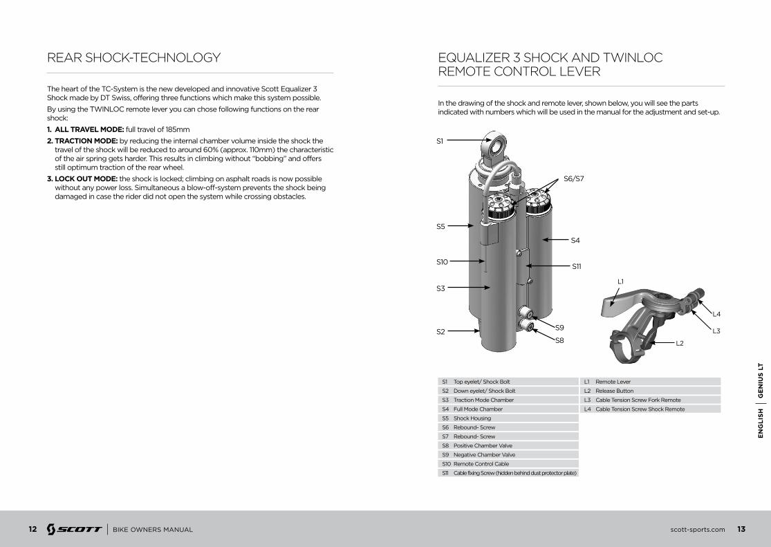
rear shock-technoLoGy
The heart of the TC-System is the new developed and innovative Scott Equalizer 3 Shock made by DT Swiss, offering three functions which make this system possible.
By using the TWINLOC remote lever you can chose following functions on the rear shock:
1. ALL TRAVeL MODe: full travel of 185mm
2. TRACTiOn MODe: by reducing the internal chamber volume inside the shock the travel of the shock will be reduced to around 60% (approx. 110mm) the characteristic of the air spring gets harder. This results in climbing without “bobbing” and offers still optimum traction of the rear wheel.
3. LOCK OuT MODe: the shock is locked; climbing on asphalt roads is now possible without any power loss. Simultaneous a blow-off-system prevents the shock being damaged in case the rider did not open the system while crossing obstacles.
equaLizer 3 shock and tWinLoc remote controL Lever
In the drawing of the shock and remote lever, shown below, you will see the parts indicated with numbers which will be used in the manual for the adjustment and set-up.
S6/S7
S3
S5
S10
S1
S4
S11
S9
S8S2
S1 Top eyelet/ Shock Bolt L1 Remote Lever
S5 Shock Housing
S9 Negative Chamber Valve
S3 Traction Mode Chamber
S7 Rebound- Screw
S11 Cable fixing Screw (hidden behind dust protector plate)
S2 Down eyelet/ Shock Bolt L2 Release Button
S6 Rebound- Screw
S10 Remote Control Cable
S4 Full Mode Chamber
L3 Cable Tension Screw Fork Remote
L4 Cable Tension Screw Shock Remote
S8 Positive Chamber Valve
L3
L4
L1
L2

14 scott-sports.com 15
Ge
niu
s LT
en
GLi
sh
BIKE OWNERS MANUAL
basic set-up of the tWinLoc remote controL of equaLizer 3 shock
To ensure perfect function of the Equalizer 3 shock it is very important to follow the steps shown below exactly.
Please note that the following explanation shows a complete exchange/replacement of the cable, so in case you just want to double check e.g. the cable tension please see only steps 1, 7, 8 and 9.
important: For all following actions the TWINLOC lever needs to be in “ALL TRAVEL-MODE” position!
Remove the cap of the cable housing window on the shock by turning the screws counter clockwise using a 1.5 mm allen key
1
remove the end cap of the cable with pliers
2
loosen the cable fixing screw (S11) by turning it counter clockwise with a 2mm allen key.
3
remove the old cable by pushing/pulling it out from the TWINLOC lever
4
insert a new cable via lever hole and cable housing and push it into the shock as shown.
5

16 scott-sports.com 17
Ge
niu
s LT
en
GLi
sh
BIKE OWNERS MANUAL
tighten the cable and fix the cablefixing screw (S11) by turning it clockwise with a 2mm allen key and a max. Tightening torque of 1.6Nm.
6
to double check accurate cable tension please push the TWINLOC lever to “Traction mode”. The mid of the cable fixing screw (S11) should be at the edge of the upper cable housing window on the shock. For fine tuning please adjust the cable tension via the barrel adjuster (L5) on the TWINLOC lever.
7
push the “open ended” cable cap on the cable until it touches the cable sled, fix it by squeezing it with pliers and cut the cable just below the cap. Keep 35mm cable length from the edge of the cable sled.
8
remount the cap of the cable housing window on the shock by turning them clockwise using a 1.5 mm allen key and a maximum tightening torque of 0.3 nm
9
important: Please note that the maximum pressure of the Equalizer 3 shock is 28.0 bars/406 psi in the positive chamber and 22.4 bars/325 psi in the negative chamber which means a max. Rider weight of 110 kgs/243 lbs incl. riding gear and load.

18 scott-sports.com 19
Ge
niu
s LT
en
GLi
sh
BIKE OWNERS MANUAL
recommended tooLs for the shock set-up
For the set-up of the shock we recommend to use a shock pump with a scale up to 40 bars/600 psi with a special air valve connector preventing from air getting away while removing the pump from the shock valve, this will result in an exact air pressure.
Please note that air will flow into the hose and indicator when counterchecking the air pressure, so you have to set up again the recommended pressure after this action.Make sure to balance at least this air loss when you make a check of the air pressure of the shock. Pls also note that the indicators of shock pumps have a tolerance of max. 10%
31 2
31 2
31 2
31 2
31 2
set-up Genius With equaLizer 3 shock
The Set-Up of the Scott/DT Equalizer 3 Shock can be easy done within a few minutes..
To adjust the air pressure of the air chamber of the Scott Equalizer 2 Shock please refer to the following instruction:
1. remove the valve cap of the positive valve (S8) which is the LOWER valve on the shock body and mount the shock pump with its adaptor on the valve.
2. pump the recommended pressure into the shock. On the shock body you will find a table showing the recommended air pressure of the positive chamber according to the rider’s weight.
3. when you reached the needed pressure remove the pump and put the valve cap on the valve
4. remove the valve cap of the negative valve (S9) which is the UPPER valve on the shock body and mount the shock pump with its adaptor on the valve
5. pump the recommended pressure into the shock. On the shock body you will find a table showing the recommended air pressure of the negative chamber according to the rider’s weight.
6. when you reached the needed pressure remove the pump and put the valve cap on the valve
AIR PRESSUREPOSITIVE
RIDERS WEIGHT AIR PRESSURENEGATIVE
KG LBS BAR PSI BAR PSI
40 88 11.0 160 8.0 116
45 99 12.0 174 8.5 123
50 110 13.0 189 9.0 131
55 121 14.0 203 10.0 145
60 132 15.0 218 10.5 152
65 143 16.0 232 11.0 160
70 154 17.0 247 12.0 174
75 165 18.0 261 12.5 181
80 176 19.0 276 13.5 196
85 187 20.0 290 14.0 203
90 198 21.0 305 14.5 210
95 209 22.0 319 15.5 225
100 220 23.0 334 16.0 232
Recommended Air Pressure

20 scott-sports.com 21
Ge
niu
s LT
en
GLi
sh
BIKE OWNERS MANUAL
SAG
The SAG should be 18mm on the shock piston, which means approx. 25% SAG in Full Travel Position
To check the adjustment, please follow as shown below:
1. Sit on the bike, put your feet on the pedal.
2. Put your feet back on the ground and stand over the bike without bouncing the bike during this action
3. Check if the SAG indicator arrow matches with the indication on the shockbody
- if arrow and indication match the air pressure is matching to your weight
- if the arrow is above the indication on the shock body the air pressure of the air chamber is too high and should be carefully reduced by using the bleed knob of the shock pump until arrow and indication match
- if the arrow is below the indication on the shock body the air pressure of the air chamber is too low and should be increased by using the shock pump until arrow and indication match
“Rebound” describes the speed the shock comes back to its original length after absorbing an obstacle.
By using the red rebound screws (S6 & S7) on the upper side of the Air Chambers you can adjust the rebound step by step.
set-up of rebound equaLizer 3 shock
Please refer to the following instruction:
Ride your bike off a pavement (remain in the saddle) and check how many times it bounces.
- if it bounces 1-2 times, the set up is good.
- If it bounces more than 3 times the rebound is too fast. Turn BOTh screws 1-2 “clicks” clockwise
- If it does not bounce the rebound is too slow. Turn BOTh screws 1-2 “clicks” counter clockwise.
S6/S7

22 scott-sports.com 23
Ge
niu
s LT
en
GLi
sh
BIKE OWNERS MANUAL
important: Please make sure that both rebound wheels show the same number below the arrow on the shock body.
In case you want even more detailed figures of air pressure or tuning hints, you can download a program under www.scott-sports.com as a MS Excel file.
important: Note that you have to mount the Scott Equalizer 3 Shock always as shown underneath.
Mounting the rear shock in a different position can cause severe damages to the frame, the linkage levers and the rear shock.
important: After a dismantlement of the rear shock, both fixing bolts should be tightened with a tightening torque of 5Nm/44in-lbs.
If this is not done correctly the rear shock can be damaged.
If you need new shock bushings/reducers and the related shock bolts to fix the shock on the frame you can order them, with
219563 Rear Shock EQ3 Mount Reducer Set
219564 Rear Shock EQ3 Mount Bolt Set
via the Scott distribution.

24 scott-sports.com 25
Ge
niu
s LT
en
GLi
sh
BIKE OWNERS MANUAL
set-up of other shock modeLs
bb standards
front deraiLLeur (fd) mountinG detaiLs
scott strongly recommends using only the scott equalizer 3 shock with the Genius LT bike, as we designed both parts for a perfect matching combination with a linear suspension rate.
If you want to use a different rear shock model than the one originally on the bike, please make sure that the shock will not in any position hit the frame and cause a damage to the frame.
Please follow the instruction below:
- Please make sure that the rear shock or its accessory parts do not touch the frame when mounting or suspending.
For doing so release the air/remove the coil, install the shock and extend the shock completely.
- If the shock touches the frame while doing so, do not use this shock in order to avoid damage to frame, swing arm or shock.
Genius LT with is available with 2 different Bottom Bracket systems.
- The carbon frames are designed for PressFit Cartridges (PF). PF BB 92 has a housing width of 89.5mm with an inner diameter for the cartridges of 41mm.
- The alloy frames are designed for 73mm threaded BB Cartridges.
On Genius LT you will find a Shimano E-type front derailleur but fixed directly on the swingarm without the plate that is fixed normally between the bottom bracket bearing cup and the bottom bracket housing of the front triangle or a SRAM Direct Mount Type S3 FD.
Please note that you always need to use the adapter plate attached to the bike or frame set between chainstay and front derailleur.
This adapter can be ordered at the Scott distribution with parts number:
219566 FD-Mount Plate Set Genius LT 2011 one size
For Genius LT carbon frames: For Genius LT alloy frames:
- Similar to Genius design - Chain plate uses same bolts as Genius - New adaptor is secured by 2xM5x9mm Allen key bolts
only for Shimano FD

26 scott-sports.com 27
Ge
niu
s LT
en
GLi
sh
BIKE OWNERS MANUAL
chainGuide
The Carbon as well as the alloy frames of Genius LT can be fitted with ISCG chainguide systems.
A set of all spare parts for this action can be ordered via the Scott distribution with
219570 Chainguide ISCG Adaptor Set Genius LT
Details for the assembly on the carbon frames of Genius LT:
Details for the assembly on the alloy frames of Genius LT:
2 Bolt Scott standard
Use 1x 15mm long bolt. Top hole is secured by chain device bolt. Not for use with guides with bashplate mounted on ISCG boss.
Triple chain blocker included with bikesUse 15mm long T25 bolts with 2.5mm spacers
ISCG ̀ 05 integrated in frame Chain Blocker mounts with 3x8mm T25 bolts, no spacers

28 scott-sports.com 29
Ge
niu
s LT
en
GLi
sh
BIKE OWNERS MANUAL
headset options scott smart cabLe routinG:
Genius LT features a tapered headset and fork steerer system to match with semi-integrated headsets of the “50-61”mm range.
The steerers of those forks are tapered from 1.5” to 1 1/8”.
This bigger diameter of the fork steerer as well as on the frame headtube helps to increase the stiffness and handling of the bike.
The direct and straight cable system on all our full suspension models allows Smart Cable Routing which is very resistant against water and dirt.
It is also possible to use forks with a standard 1 1/8” steerer tube when using a reducer headset such as e.g.
Ritchey WCS Carbon Zero Tapered PF 50-61mm 18mm UD for 1 1/8 fork
Ritchey WCS Carbon Zero Tapered PF 50-61mm 18mm UD
Ritchey PRO Tapered PF 50-61mm 12.9mm
30 scott-sports.com 31
Ge
niu
s LT
en
GLi
sh
BIKE OWNERS MANUAL
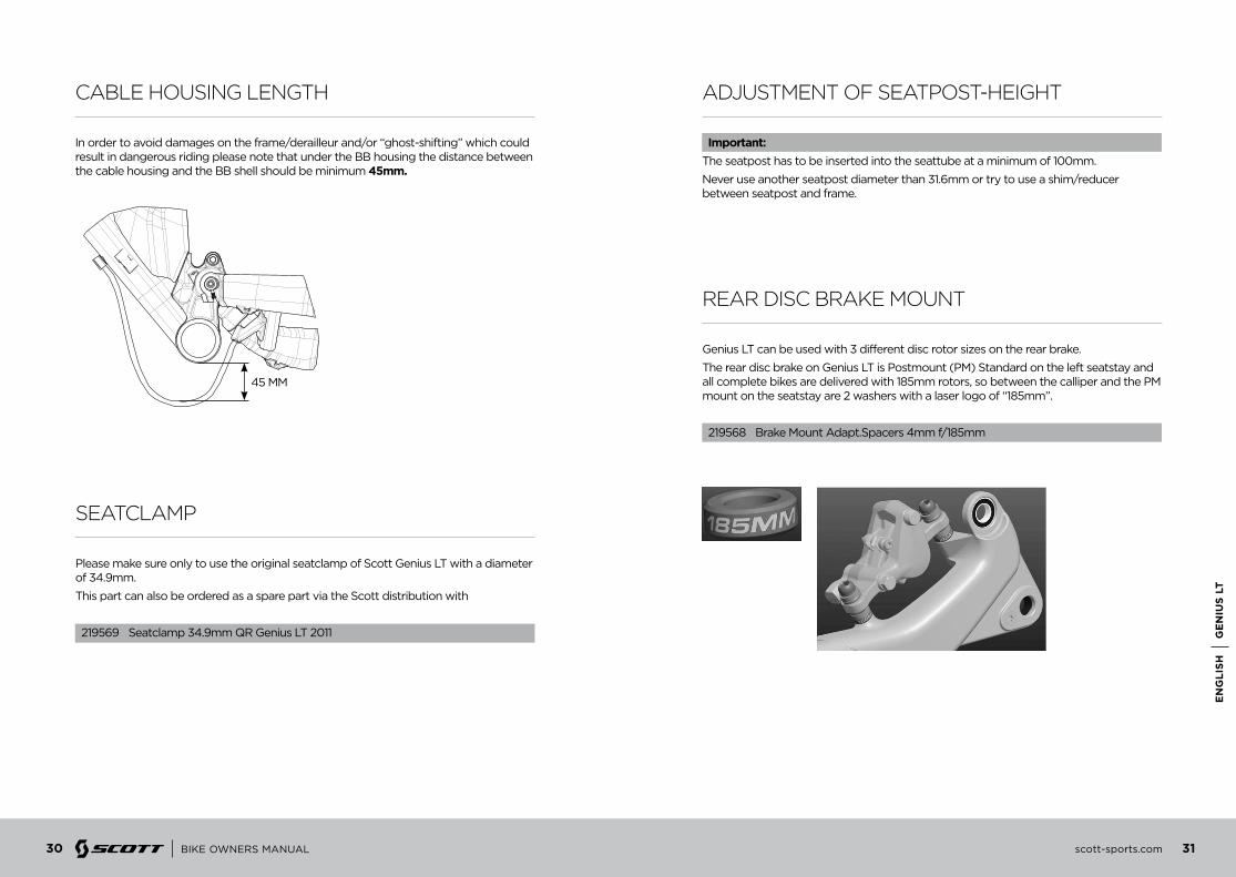
cabLe housinG LenGth
seatcLamp
In order to avoid damages on the frame/derailleur and/or “ghost-shifting” which could result in dangerous riding please note that under the BB housing the distance between the cable housing and the BB shell should be minimum 45mm.
Please make sure only to use the original seatclamp of Scott Genius LT with a diameter of 34.9mm.
This part can also be ordered as a spare part via the Scott distribution with
219569 Seatclamp 34.9mm QR Genius LT 2011
45 MM
adjustment of seatpost-heiGht
rear disc brake mount
important:The seatpost has to be inserted into the seattube at a minimum of 100mm.
Never use another seatpost diameter than 31.6mm or try to use a shim/reducer between seatpost and frame.
Genius LT can be used with 3 different disc rotor sizes on the rear brake.
The rear disc brake on Genius LT is Postmount (PM) Standard on the left seatstay and all complete bikes are delivered with 185mm rotors, so between the calliper and the PM mount on the seatstay are 2 washers with a laser logo of “185mm”.
219568 Brake Mount Adapt.Spacers 4mm f/185mm

32 scott-sports.com 33
Ge
niu
s LT
en
GLi
sh
BIKE OWNERS MANUAL
It is also possible to use 180mm rotors. To do so, please remove the 2 washers with a laser logo of “185mm” and fix the calliper directly on the PM on the seatstay.
In case you want to use a rotor with 203mm please use an adapter offered by the manufacturer of the brake system of your choice.
This adaptor needs to be assembled between PM and the calliper.
important:Please note that it is not possible to use other rotor dimensions than those shown in the text above!
ids 2 / repLaceabLe dropout
All Genius LT bikes feature the new IDS 2 System of Scott.
3 different version of IDS 2 are available,
- RWS 12/142
- RWS 12/135
- RWS 5/135
They all can only be used in combination with the DT Swiss RWS skewer/axle.
Axle Skewer

34 scott-sports.com 35
Ge
niu
s LT
en
GLi
sh
BIKE OWNERS MANUAL
Options:
1. RWs 12/142The RWS 12/142 features a rear hub width of 142mm for 12mm through axle which only matches with the related 142mm rear dropouts in combination with the 12mm DT RWS.
219574 Dropout Set IDS 2 142/RWS 12
2. RWs 12/135The RWS 12/135 features a rear hub width of 135mm for 12mm through axle which only matches with the related 135mm rear dropouts in combination with the 12mm DT RWS.
219573 Dropout Set IDS 2 135/RWS 12
3. RWs 5/135The RWS 5/135 features a rear hub width of 135mm for regular QR axles which only matches with the related 135mm rear dropouts in combination with the 5mm DT RWS.
219572 Dropout Set IDS 2 135/RWS 5
Beside the complete sets as shown above for a change of the rear hub/axle system you can also order the right side RD hanger separately via the Scott distribution in case you need this to repair a damage on the RD hanger.
219575 Dropout Hanger right side IDS 2 135/RWS5
219576 Dropout Hanger right side IDS 2 135/RWS12
219577 Dropout Hanger right side IDS 2 142/RWS12
front fork set-up/ chanGe of front fork
For the set up of the front fork please use the fork specific manual attached to the bike.
We recommend using front forks with a travel of 180mm (565mm from mid of axle - top of crown), as this will not influence the geometry and alter handling of the bike.
pivot maintenance
The pivot and bearings on SCOTT Genius LT are extremely easy to maintain.
An external treatment with a grease spray after every bike wash is all you have to do. We do not recommend heavy grease sprays since these will leave a film on the parts which is difficult to remove. We recommend the same for the chain also.
If you have to change the bearings you can order them included in a service kit at your local SCOTT dealer with
219565 Swingarm-Rep. Kit Genius LT
or buy them with international parts number as shown below in a hardware store.
- 4 x 6802 (15x24x5mm)
- 2 x 6803 (17x26x5mm)
- 2 x 61800 (10x19x5mm)
In case of a change of the bearings or of the rear swingarm you should contact your local SCOTT dealer as you need special tools for disassembly and assembly.
important:No triple clamp forks are allowed on Genius LT!

36 scott-sports.com 37
Ge
niu
s LT
en
GLi
sh
BIKE OWNERS MANUAL
Warranty
Model . . . . . . . . . . . . . . . . . . . . . . . . . . . . . . . . . . . . . . . . . . . . . . . . . . . . . . . . . . . . . . . . . . . . . . . . . . . . . . . . .
Year . . . . . . . . . . . . . . . . . . . . . . . . . . . . . . . . . . . . . . . . . . . . . . . . . . . . . . . . . . . . . . . . . . . . . . . . . . . . . . . . . . .
Size . . . . . . . . . . . . . . . . . . . . . . . . . . . . . . . . . . . . . . . . . . . . . . . . . . . . . . . . . . . . . . . . . . . . . . . . . . . . . . . . . . .
Frame Nr. . . . . . . . . . . . . . . . . . . . . . . . . . . . . . . . . . . . . . . . . . . . . . . . . . . . . . . . . . . . . . . . . . . . . . . . . . . . . .
Shock Nr. . . . . . . . . . . . . . . . . . . . . . . . . . . . . . . . . . . . . . . . . . . . . . . . . . . . . . . . . . . . . . . . . . . . . . . . . . . . . .
Date of purchase . . . . . . . . . . . . . . . . . . . . . . . . . . . . . . . . . . . . . . . . . . . . . . . . . . . . . . . . . . . . . . . . . . . . . .
Warranty
SCOTT bikes are made using the most innovative production and quality methods. They are equipped with best components of well known parts suppliers.
Doing so SCOTT warrants its frames and swingarms for five years (subject to compliance with maintenance ranges, see below) and SCOTT forks (provided it is a fork of SCOTT) for two years for defects in material and/or workmanship in case of purchase of completely assembled bikes.
This warranty of 5 years for the frames shall only be granted in case once a year a maintenance service has been effected according to maintenance requirements as set forth in this manual by an authorised SCOTT dealer.
The authorised SCOTT dealer shall confirm the effected annual maintenance service by stamp and signature.
In case such an annual maintenance service has not been effected the warranty of 5 years for the frame shall be reduced to 3 years.
Costs for maintenance and service have to be born by the owner of the SCOTT bike.
On Gambler, Voltage Fr and Volt-X the warranty period is limited to 2 years.
The warranty period starts at the day of purchase. This warranty is limited to the first buyer, what means the first person who uses the bike and only with the use it was made for. Furthermore, this warranty is limited to purchases via authorized SCOTT-dealers
The warranty is solely granted in case of purchase of a completely assembled bike to the explicit exclusion of purchases of not completely assembled bikes.
In case of a warranty claim the decision to repair or to replace the defective part is up to SCOTT. Non defective parts will only be replaced at the guarantee’s own expense.
Fair wear and tear is not covered by the warranty. A complete list of all parts of wear and tear can be found in the next chapter of this manual.
In addition, you will find at the end of this manual a protocol for the handing over of the bike which will remain in copy at the SCOTT dealer after acceptance and signature of the consumer.
It is obligatory to show this protocol of handing over together with the defective part in case of a warranty claim given that it provides evidence of purchase. Otherwise no warranty is granted.
In principle, this warranty is granted worldwide. Claims must be made through an authorized dealer, for information regarding the nearest dealer, write or call this company or the national SCOTT distributor.
Normal wear, accident, neglect, abuse, improper assembly, improper maintenance by other than an authorized dealer or use of parts or devices not consistent with the use originally intended for the bicycle as sold are not covered by this warranty.
Hereby SCOTT grants a voluntarily manufacturer’s warranty. Additional entitlements according to national warrant of merchantability are reserved.
For warranty info on the Equalizer 2 shock please refer to the attached manual of DT Swiss.