Genie GS-3246 Service Manual - Rentalex · 2017-05-04 · Genie GS-2046 and GS-2646 and GS-3246...
236
Service Manual Part No. 72972 September 2006 Rev B2
Transcript of Genie GS-3246 Service Manual - Rentalex · 2017-05-04 · Genie GS-2046 and GS-2646 and GS-3246...
Service Manual Part No. 72972
September 2006
Rev B2
Genie GS-2046 and GS-2646 and GS-3246 Part No. 72972
June 2003
ii
Introduction
Important
Read, understand and obey the safety rules andoperating instructions in the Genie GS-2032 andGS-2632 and GS-2046 and GS-2646 and GS-3246Operator's Manual before attempting anymaintenance or repair procedure.
This manual provides detailed scheduledmaintenance information for the machine ownerand user. It also provides troubleshooting andrepair procedures for qualified serviceprofessionals.
Basic mechanical, hydraulic and electricalskills are required to perform most procedures.However, several procedures require specializedskills, tools, lifting equipment and a suitableworkshop. In these instances, we stronglyrecommend that maintenance and repair beperformed at an authorized Genie dealerservice center.
Technical Publications
Genie Industries has endeavored to deliver thehighest degree of accuracy possible. However,continuous improvement of our products is a Geniepolicy. Therefore, product specificationsare subject to change without notice.
Readers are encouraged to notify Genie of errorsand send in suggestions for improvement. Allcommunications will be carefully considered forfuture printings of this and all other manuals.
Contact Us:
PO Box 97030Redmond, WA 98073-9730 USA
www.genieindustries.come-mail: [email protected]
Copyright © 1997 by Genie Industries
72972 Rev B June 2003Second Edition, Second Printing
"Genie" is a registered trademark of GenieIndustries in the USA and many other countries."GS" is a trademark of Genie Industries.
Printed on recycled paper
Printed in U.S.A.
Serial Number Information
Genie Industries offers the following ServiceManuals for these models:
Title Part No.
Genie GS-2046 and GS-2646 and GS-3246Service Manual (before serial number 17408) .... 48339
Part No. 72972 Genie GS-2046 and GS-2646 and GS-3246
June 2003
iii
Safety Rules
Section 1 • Safety Rules
DangerFailure to obey the instructions and safety rulesin this manual and the Genie GS-2032 andGS-2632 and GS-2046 and GS-2646 and GS-3246Operator's Manual will result in death or seriousinjury.
Many of the hazards identified in theoperator’s manual are also safety hazardswhen maintenance and repair proceduresare performed.
Do Not Perform MaintenanceUnless:
You are trained and qualified to performmaintenance on this machine.
You read, understand and obey:- manufacturer’s instructions and safety rules- employer’s safety rules and worksite
regulations- applicable governmental regulations
You have the appropriate tools, liftingequipment and a suitable workshop.
Genie GS-2046 and GS-2646 and GS-3246 Part No. 72972
June 2003
SAFETY RULES
Personal SafetyAny person working on or around a machine mustbe aware of all known safety hazards. Personalsafety and the continued safe operation of themachine should be your top priority.
Read each procedure thoroughly. Thismanual and the decals on the machine,use signal words to identify the following:
Safety alert symbol—used to alertpersonnel to potential personalinjury hazards. Obey all safetymessages that follow this symbolto avoid possible injury or death.
Red—used to indicate thepresence of an imminentlyhazardous situation which, if notavoided, will result in death orserious injury.
Orange—used to indicate thepresence of a potentiallyhazardous situation which, if notavoided, could result in death orserious injury.
Yellow with safety alert symbol—used to indicate the presence of apotentially hazardous situationwhich, if not avoided, may causeminor or moderate injury.
Yellow without safety alertsymbol—used to indicate thepresence of a potentiallyhazardous situation which, if notavoided, may result in propertydamage.
Green—used to indicate operationor maintenance information.
iv
Be sure to wear protective eye wear andother protective clothing if the situationwarrants it.
Be aware of potential crushing hazardssuch as moving parts, free swinging orunsecured components when lifting or
placing loads. Always wear approved steel-toedshoes.
Workplace SafetyBe sure to keep sparks, flames andlighted tobacco away from flammable andcombustible materials like battery gases
and engine fuels. Always have an approved fireextinguisher within easy reach.
Be sure that all tools and working areasare properly maintained and ready foruse. Keep work surfaces clean and free of
debris that could get into machine components andcause damage.
Be sure any forklift, overhead crane orother lifting or supporting device is fullycapable of supporting and stabilizing the
weight to be lifted. Use only chains or straps thatare in good condition and of ample capacity.
Be sure that fasteners intended for onetime use (i.e., cotter pins and self-lockingnuts) are not reused. These components
may fail if they are used a second time.
Be sure to properly dispose of old oil orother fluids. Use an approved container.Please be environmentally safe .
Be sure that your workshop or work areais properly ventilated and well lit.
Section 1 • Safety Rules
Part No. 72972 Genie GS-2046 and GS-2646 and GS-3246
June 2003
Table of Contents
v
Introduction
Important Information ...................................................................................................... ii
Section One Safety Rules
General Safety Rules ..................................................................................................... iii
Section Two Specifications - Rev B
Machine Specifications ............................................................................................. 2 - 1
Performance Specifications ...................................................................................... 2 - 2
Hydraulic Specifications ............................................................................................ 2 - 3
Manifold Component Specifications .......................................................................... 2 - 4
Hydraulic Hose and Fitting Torque Specifications ..................................................... 2 - 6
Section Three Scheduled Maintenance Procedures
Introduction ............................................................................................................... 3 - 1
Pre-delivery Preparation Report ................................................................................. 3 - 3
Maintenance Inspection Report ................................................................................. 3 - 5
Checklist A Procedures - Rev B
A-1 Perform Pre-operation Inspection .................................................................... 3 - 6
A-2 Perform Function Tests ................................................................................... 3 - 6
A-3 Perform 30 Day Service .................................................................................. 3 - 7
A-4 Grease the Steer Yokes .................................................................................. 3 - 7
Genie GS-2046 and GS-2646 and GS-3246 Part No. 72972
September 2006
TABLE OF CONTENTS
vi
Section Three Maintenance Procedures, continued
Checklist B Procedures - Rev C
B-1 Inspect the Batteries ....................................................................................... 3 - 8
B-2 Inspect the Electrical Wiring ............................................................................ 3 - 9
B-3 Inspect the Tires and Wheels (including castle nut torque) ............................ 3 - 10
B-4 Test the Key Switch ...................................................................................... 3 - 10
B-5 Test the Automotive-style Horn (if equipped) ................................................. 3 - 11
B-6 Test the Drive Brakes.................................................................................... 3 - 12
B-7 Test the Drive Speed - Stowed Position ........................................................ 3 - 14
B-8 Test the Drive Speed - Raised Position ......................................................... 3 - 15
B-9 Perform Hydraulic Oil Analysis ...................................................................... 3 - 16
B-10 Replace the Hydraulic Tank Return Filter ....................................................... 3 - 16
B-11 Check the Module Tray Latch Components ................................................... 3 - 17
Checklist C Procedure - Rev C
C-1 Check the Scissor Arm Wear Pads ............................................................... 3 - 19
Checklist D Procedure - Rev A
D-1 Test or Replace the Hydraulic Oil .................................................................. 3 - 20
Part No. 72972 Genie GS-2046 and GS-2646 and GS-3246
June 2003
TABLE OF CONTENTS
vii
Section Four Repair Procedures
Introduction ............................................................................................................... 4 - 1
Platform Controls - Rev B
1-1 Circuit Boards .................................................................................................. 4 - 2
1-2 Joystick Controller ........................................................................................... 4 - 3
1-3 Controller Adjustments .................................................................................... 4 - 5
1-4 Software Configuration .................................................................................. 4 - 13
Platform Components - Rev A
2-1 Platform ........................................................................................................ 4 - 16
2-2 Platform Extension ........................................................................................ 4 - 17
Scissor Components - Rev A
3-1 Scissor Assembly, GS-2046 ......................................................................... 4 - 18
3-2 Scissor Assembly, GS-2646 ......................................................................... 4 - 24
3-3 Scissor Assembly, GS-3246 ......................................................................... 4 - 32
3-4 Lift Cylinder ................................................................................................... 4 - 42
Ground Controls - Rev B
4-1 Manual Platform Lowering Cable, GS-2046 and GS-2646 .............................. 4 - 46
4-2 Manual Platform Lowering, GS-3246 .............................................................. 4 - 47
4-3 Toggle Switches ............................................................................................ 4 - 48
4-4 Control Relays ............................................................................................... 4 - 49
4-5 Tilt Level Sensor (before serial number 50444) .............................................. 4 - 50
4-6 Tilt Level Sensor (after serial number 50443) ................................................. 4 - 54
Genie GS-2046 and GS-2646 and GS-3246 Part No. 72972
June 2003
TABLE OF CONTENTS
viii
Section Four Repair Procedures, continued
Hydraulic Pump - Rev A
5-1 Function Pump .............................................................................................. 4 - 58
Function Manifold - Rev B
6-1 Function Manifold Components(from serial number 17408 to 17481) .............................................................. 4 - 60
6-2 Function Manifold Components(from serial number 17482 to 36044) .............................................................. 4 - 62
6-3 Function Manifold Components(after serial number 36044) ............................................................................ 4 - 64
6-4 Function Manifold Components - Models with Traction Control ...................... 4 - 66
6-5 Valve Adjustments - Function Manifold ......................................................... 4 - 68
6-6 Platform Lift Relief Valve Manifold Components, GS-3246 Models(before serial number 36045) ......................................................................... 4 - 75
6-7 Valve Adjustments - Lift Relief Manifold, GS-3246 Models(before serial number 36045) ......................................................................... 4 - 76
6-8 Valve Coils .................................................................................................... 4 - 78
Hydraulic Tank - Rev A
7-1 Hydraulic Tank .............................................................................................. 4 - 80
Steer Axle Components - Rev A
8-1 Yoke and Drive Motor .................................................................................... 4 - 81
8-2 Steer Cylinder ................................................................................................ 4 - 83
8-3 Steer Bellcrank .............................................................................................. 4 - 84
Non-steer Axle Components - Rev A
9-1 Drive Brake ................................................................................................... 4 - 85
Brake Release Hand Pump Components - Rev A
10-1 Brake Release Hand Pump Components ....................................................... 4 - 86
Part No. 72972 Genie GS-2046 and GS-2646 and GS-3246
June 2003
TABLE OF CONTENTS
ix
Section Five Troubleshooting Flow Charts and Fault Codes
Introduction ............................................................................................................... 5 - 1
Fault Code Chart (after serial number 17407) - Rev A................................................ 5 - 3
ChartNumber Chart Title
1 All Functions Will Not Operate - Rev A ..................................................................... 5 - 4
2 Pump Motor Will Not Operate - Rev A ....................................................................... 5 - 6
3 All Functions Inoperative, Power Unit Starts and Runs - Rev A................................. 5 - 8
4 Ground Controls Inoperative,Platform Controls Operate Normally - Rev A ............................................................ 5 - 9
5 Platform Controls Inoperative,Ground Controls Operate Normally - Rev A............................................................ 5 - 10
6 Platform Up Function Inoperative - Rev A ............................................................... 5 - 11
7 Platform Down Function Inoperative - Rev A .......................................................... 5 - 12
8 Steer Left Function Inoperative - Rev A .................................................................. 5 - 14
9 Steer Right Function Inoperative - Rev A ................................................................ 5 - 16
10 All Drive Functions Inoperative,All Other Functions Operate Normally - Rev A ........................................................ 5 - 18
10A Brake Release Function Inoperative - Rev A ........................................................... 5 - 19
11 Drive Forward Function Inoperative - Rev A ............................................................ 5 - 20
12 Drive Reverse Function Inoperative - Rev A ............................................................ 5 - 21
13 Machine Will Not Drive At Full Speed - Rev A ......................................................... 5 - 22
14 Machine Drives At Full Speed With Platform Raised - Rev A .................................. 5 - 23
15 Limit Switch Function Inoperative - Rev A ............................................................... 5 - 24
16 Fault Code 02 - ECM / Platform Communication Error - Rev A ................................ 5 - 26
17 Fault Code 59 - Parallel/Series Coil Fault - Rev B ................................................... 5 - 29
Genie GS-2046 and GS-2646 and GS-3246 Part No. 72972
June 2003
x
TABLE OF CONTENTS
Section Six Schematics
Introduction ............................................................................................................... 6 - 1
Control Relay Layout - Rev A .................................................................................... 6 - 2
ECM Pin-out Legend - Rev B .................................................................................... 6 - 4
Platform Controls Wiring Diagram(from serial number 17408 to 48054) - Rev B ............................................................ 6 - 6
Platform Controls Wiring Diagram(after serial number 48054) - Rev A ........................................................................... 6 - 7
Ground Controls Wiring Diagram, GS-2046 and GS-2646 - Rev B ............................. 6 - 8
Ground Controls Wiring Diagram, GS-3246 - Rev B ................................................... 6 - 9
Level Sensor Box Wiring Diagram - Rev A .............................................................. 6 - 10
Electrical Symbols Legend - Rev B ......................................................................... 6 - 12
Electrical Schematic(from serial number 17408 to 21064) - Rev B .......................................................... 6 - 13
Electrical Schematic(from serial number 21065 to 21262) - Rev B .......................................................... 6 - 15
Electrical Schematic(from serial number 21263 to 24438) - Rev B .......................................................... 6 - 17
Electrical Schematic(from serial number 24439 to 25141) - Rev B .......................................................... 6 - 19
Electrical Schematic(from serial number 25142 to 27181) - Rev B .......................................................... 6 - 21
Electrical Schematic(from serial number 27182 to 28936) - Rev B .......................................................... 6 - 23
Electrical Schematic(from serial number 28937 to 33721) - Rev B .......................................................... 6 - 25
Electrical Schematic(from serial number 33722 to 40925) - Rev B .......................................................... 6 - 27
Part No. 72972 Genie GS-2046 and GS-2646 and GS-3246
June 2003
Section Six Schematics, continued
Electrical Schematic(from serial number 40926 to 48054) - Rev B .......................................................... 6 - 29
Electrical Schematic(from serial number 48055 to 48717) - Rev A .......................................................... 6 - 31
Electrical Schematic(from serial number 48718 to 49199) - Rev A .......................................................... 6 - 33
Electrical Schematic(after serial number 49199) - Rev A ......................................................................... 6 - 35
Hydraulic Symbols Legend and Component Reference - Rev B............................... 6 - 37
Hydraulic Schematic, GS-2046 and GS-2646(from serial number 17408 to 36044) - Rev A .......................................................... 6 - 38
Hydraulic Schematic, GS-2046 and GS-2646(after serial number 36044) - Rev A ......................................................................... 6 - 39
Hydraulic Schematic, GS-2046 and GS-2646Models with Traction Control - Rev A ...................................................................... 6 - 40
Hydraulic Schematic, GS-3246(from serial number 17408 to 22446) - Rev A .......................................................... 6 - 41
Hydraulic Schematic, GS-3246(from serial number 22447 to 27181) - Rev A .......................................................... 6 - 42
Hydraulic Schematic, GS-3246(from serial number 27182 to 36044) - Rev A .......................................................... 6 - 43
Hydraulic Schematic, GS-3246(after serial number 36044) - Rev A ......................................................................... 6 - 44
Hydraulic Schematic, GS-3246Models with Traction Control - Rev A ...................................................................... 6 - 45
TABLE OF CONTENTS
xi
Genie GS-2046 and GS-2646 and GS-3246 Part No. 72972
June 2003
This page intentionally left blank.
Part No. 72972 Genie GS-2046 and GS-2646 and GS-3246 2 - 1
Section 2 • SpecificationsMay 2003
REV B Specifications
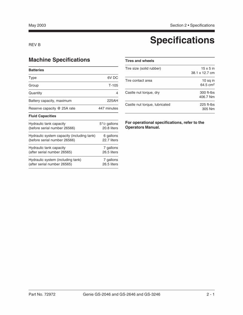
Machine Specifications
Batteries
Type 6V DC
Group T-105
Quantity 4
Battery capacity, maximum 225AH
Reserve capacity @ 25A rate 447 minutes
Fluid Capacities
Hydraulic tank capacity 51/2 gallons(before serial number 26566) 20.8 liters
Hydraulic system capacity (including tank) 6 gallons(before serial number 26566) 22.7 liters
Hydraulic tank capacity 7 gallons(after serial number 26565) 26.5 liters
Hydraulic system (including tank) 7 gallons(after serial number 26565) 26.5 liters
Tires and wheels
Tire size (solid rubber) 15 x 5 in38.1 x 12.7 cm
Tire contact area 10 sq in64.5 cm2
Castle nut torque, dry 300 ft-lbs 406.7 Nm
Castle nut torque, lubricated 225 ft-lbs 305 Nm
For operational specifications, refer to theOperators Manual.
2 - 2 Genie GS-2046 and GS-2646 and GS-3246 Part No. 72972
Section 2 • Specifications May 2003
REV BSPECIFICATIONS
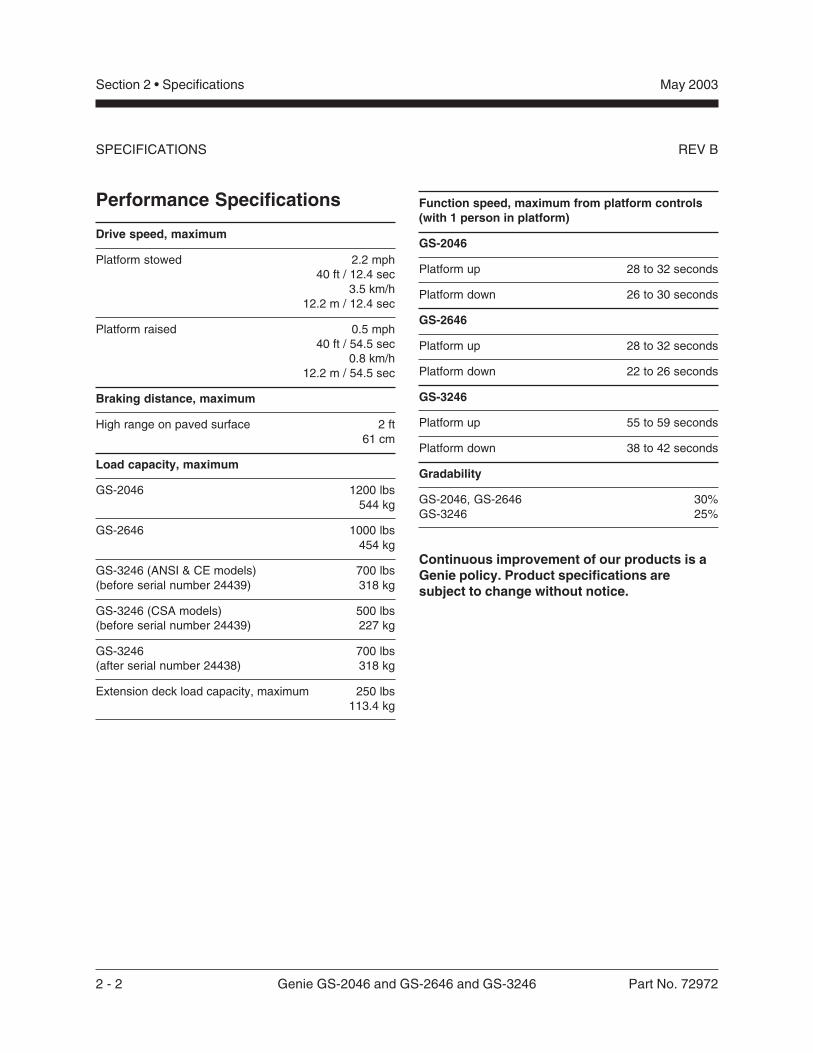
Performance Specifications
Drive speed, maximum
Platform stowed 2.2 mph40 ft / 12.4 sec
3.5 km/h12.2 m / 12.4 sec
Platform raised 0.5 mph40 ft / 54.5 sec
0.8 km/h12.2 m / 54.5 sec
Braking distance, maximum
High range on paved surface 2 ft61 cm
Load capacity, maximum
GS-2046 1200 lbs 544 kg
GS-2646 1000 lbs 454 kg
GS-3246 (ANSI & CE models) 700 lbs(before serial number 24439) 318 kg
GS-3246 (CSA models) 500 lbs(before serial number 24439) 227 kg
GS-3246 700 lbs(after serial number 24438) 318 kg
Extension deck load capacity, maximum 250 lbs113.4 kg
Function speed, maximum from platform controls(with 1 person in platform)
GS-2046
Platform up 28 to 32 seconds
Platform down 26 to 30 seconds
GS-2646
Platform up 28 to 32 seconds
Platform down 22 to 26 seconds
GS-3246
Platform up 55 to 59 seconds
Platform down 38 to 42 seconds
Gradability
GS-2046, GS-2646 30%GS-3246 25%
Continuous improvement of our products is aGenie policy. Product specifications aresubject to change without notice.
Part No. 72972 Genie GS-2046 and GS-2646 and GS-3246 2 - 3
Section 2 • SpecificationsMay 2003
REV B SPECIFICATIONS
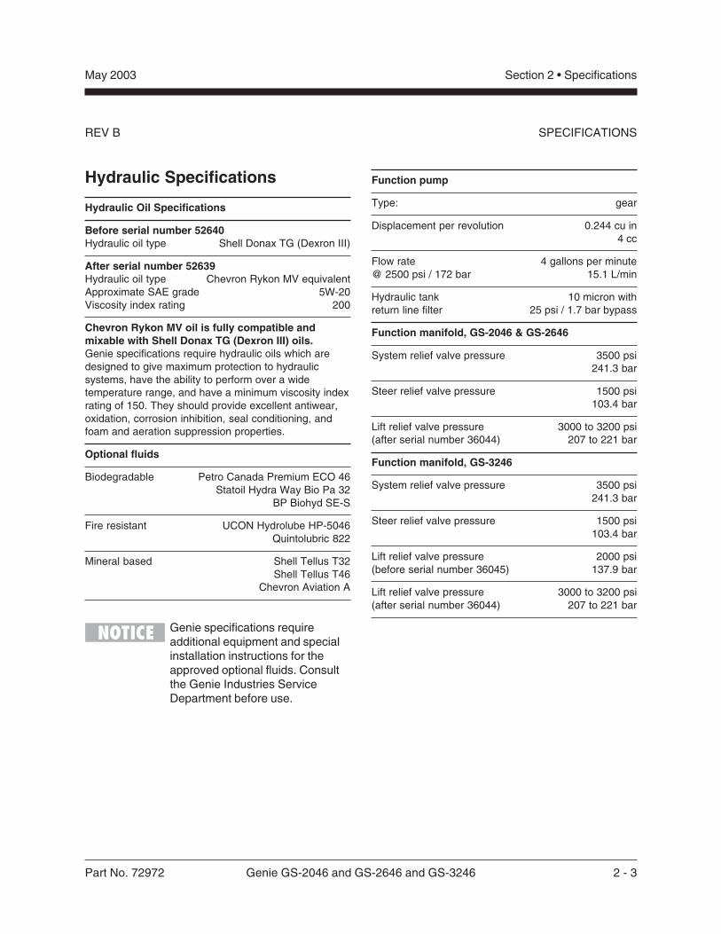
Hydraulic Specifications
Hydraulic Oil Specifications
Before serial number 52640Hydraulic oil type Shell Donax TG (Dexron III)
After serial number 52639Hydraulic oil type Chevron Rykon MV equivalentApproximate SAE grade 5W-20Viscosity index rating 200
Chevron Rykon MV oil is fully compatible andmixable with Shell Donax TG (Dexron III) oils.Genie specifications require hydraulic oils which aredesigned to give maximum protection to hydraulicsystems, have the ability to perform over a widetemperature range, and have a minimum viscosity indexrating of 150. They should provide excellent antiwear,oxidation, corrosion inhibition, seal conditioning, andfoam and aeration suppression properties.
Optional fluids
Biodegradable Petro Canada Premium ECO 46Statoil Hydra Way Bio Pa 32
BP Biohyd SE-S
Fire resistant UCON Hydrolube HP-5046Quintolubric 822
Mineral based Shell Tellus T32Shell Tellus T46
Chevron Aviation A
Genie specifications requireadditional equipment and specialinstallation instructions for theapproved optional fluids. Consultthe Genie Industries ServiceDepartment before use.
Function pump
Type: gear
Displacement per revolution 0.244 cu in4 cc
Flow rate 4 gallons per minute@ 2500 psi / 172 bar 15.1 L/min
Hydraulic tank 10 micron withreturn line filter 25 psi / 1.7 bar bypass
Function manifold, GS-2046 & GS-2646
System relief valve pressure 3500 psi241.3 bar
Steer relief valve pressure 1500 psi103.4 bar
Lift relief valve pressure 3000 to 3200 psi(after serial number 36044) 207 to 221 bar
Function manifold, GS-3246
System relief valve pressure 3500 psi241.3 bar
Steer relief valve pressure 1500 psi103.4 bar
Lift relief valve pressure 2000 psi(before serial number 36045) 137.9 bar
Lift relief valve pressure 3000 to 3200 psi(after serial number 36044) 207 to 221 bar
2 - 4 Genie GS-2046 and GS-2646 and GS-3246 Part No. 72972
Section 2 • Specifications May 2003
REV BSPECIFICATIONS
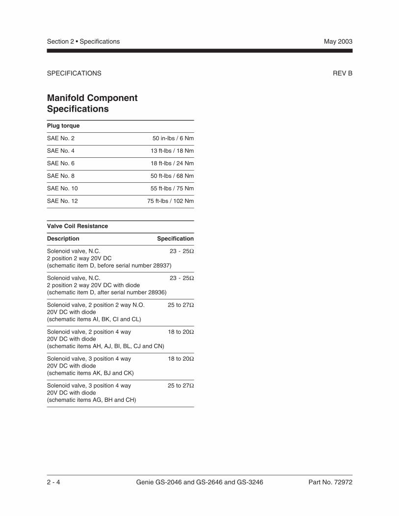
Manifold ComponentSpecifications
Plug torque
SAE No. 2 50 in-lbs / 6 Nm
SAE No. 4 13 ft-lbs / 18 Nm
SAE No. 6 18 ft-lbs / 24 Nm
SAE No. 8 50 ft-lbs / 68 Nm
SAE No. 10 55 ft-lbs / 75 Nm
SAE No. 12 75 ft-lbs / 102 Nm
Valve Coil Resistance
Description Specification
Solenoid valve, N.C. 23 - 25Ω2 position 2 way 20V DC(schematic item D, before serial number 28937)
Solenoid valve, N.C. 23 - 25Ω2 position 2 way 20V DC with diode(schematic item D, after serial number 28936)
Solenoid valve, 2 position 2 way N.O. 25 to 27Ω20V DC with diode(schematic items AI, BK, CI and CL)
Solenoid valve, 2 position 4 way 18 to 20Ω20V DC with diode(schematic items AH, AJ, BI, BL, CJ and CN)
Solenoid valve, 3 position 4 way 18 to 20Ω20V DC with diode(schematic items AK, BJ and CK)
Solenoid valve, 3 position 4 way 25 to 27Ω20V DC with diode(schematic items AG, BH and CH)
Part No. 72972 Genie GS-2046 and GS-2646 and GS-3246 2 - 5
Section 2 • SpecificationsMay 2003
REV B
This page intentionally left blank.
SPECIFICATIONS
2 - 6 Genie GS-2046 and GS-2646 and GS-3246 Part No. 72972
Section 2 • Specifications May 2003
REV A
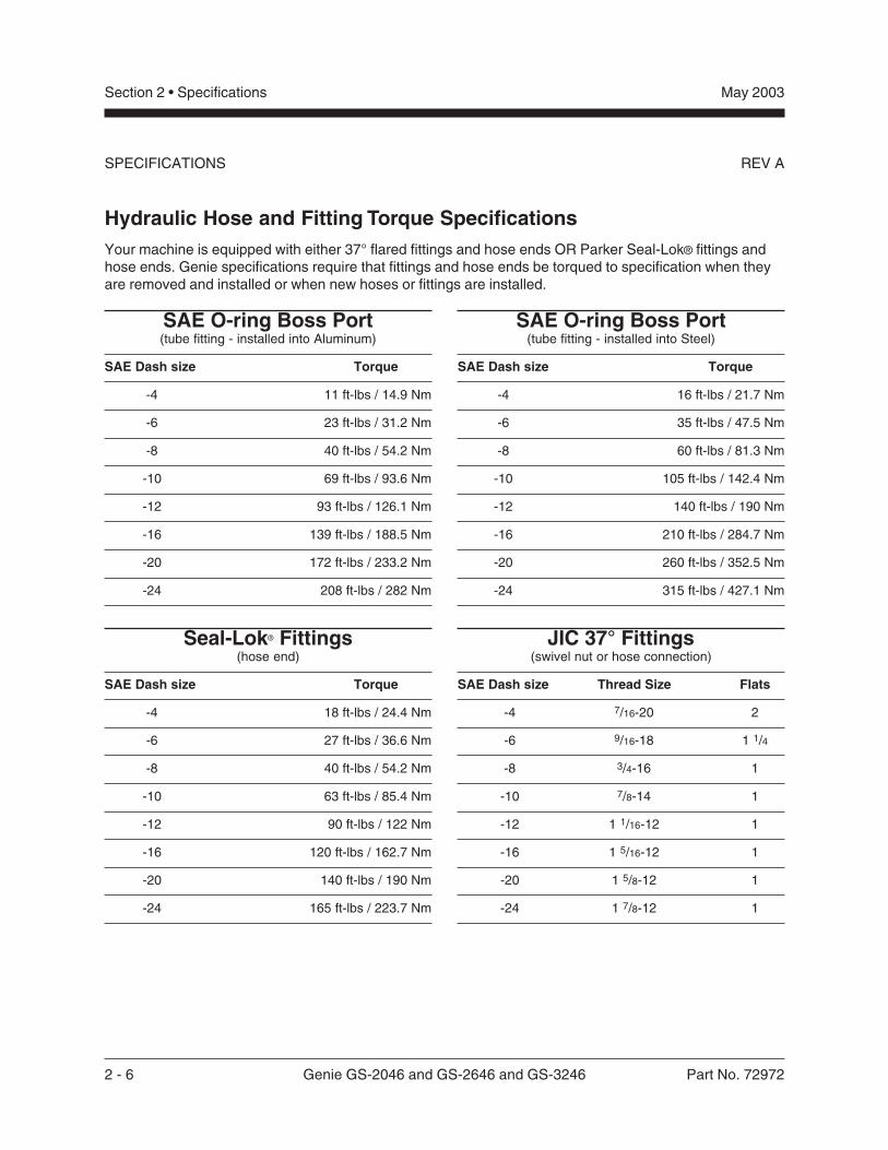
Hydraulic Hose and Fitting Torque SpecificationsYour machine is equipped with either 37° flared fittings and hose ends OR Parker Seal-Lok® fittings andhose ends. Genie specifications require that fittings and hose ends be torqued to specification when theyare removed and installed or when new hoses or fittings are installed.
SAE O-ring Boss Port(tube fitting - installed into Aluminum)
SAE Dash size Torque
-4 11 ft-lbs / 14.9 Nm
-6 23 ft-lbs / 31.2 Nm
-8 40 ft-lbs / 54.2 Nm
-10 69 ft-lbs / 93.6 Nm
-12 93 ft-lbs / 126.1 Nm
-16 139 ft-lbs / 188.5 Nm
-20 172 ft-lbs / 233.2 Nm
-24 208 ft-lbs / 282 Nm
SAE O-ring Boss Port(tube fitting - installed into Steel)
SAE Dash size Torque
-4 16 ft-lbs / 21.7 Nm
-6 35 ft-lbs / 47.5 Nm
-8 60 ft-lbs / 81.3 Nm
-10 105 ft-lbs / 142.4 Nm
-12 140 ft-lbs / 190 Nm
-16 210 ft-lbs / 284.7 Nm
-20 260 ft-lbs / 352.5 Nm
-24 315 ft-lbs / 427.1 Nm
Seal-Lok® Fittings(hose end)
SAE Dash size Torque
-4 18 ft-lbs / 24.4 Nm
-6 27 ft-lbs / 36.6 Nm
-8 40 ft-lbs / 54.2 Nm
-10 63 ft-lbs / 85.4 Nm
-12 90 ft-lbs / 122 Nm
-16 120 ft-lbs / 162.7 Nm
-20 140 ft-lbs / 190 Nm
-24 165 ft-lbs / 223.7 Nm
JIC 37° Fittings(swivel nut or hose connection)
SAE Dash size Thread Size Flats
-4 7/16-20 2
-6 9/16-18 1 1/4
-8 3/4-16 1
-10 7/8-14 1
-12 1 1/16-12 1
-16 1 5/16-12 1
-20 1 5/8-12 1
-24 1 7/8-12 1
SPECIFICATIONS
Part No. 72972 Genie GS-2046 and GS-2646 and GS-3246 2 - 7
Section 2 • SpecificationsMay 2003
REV A
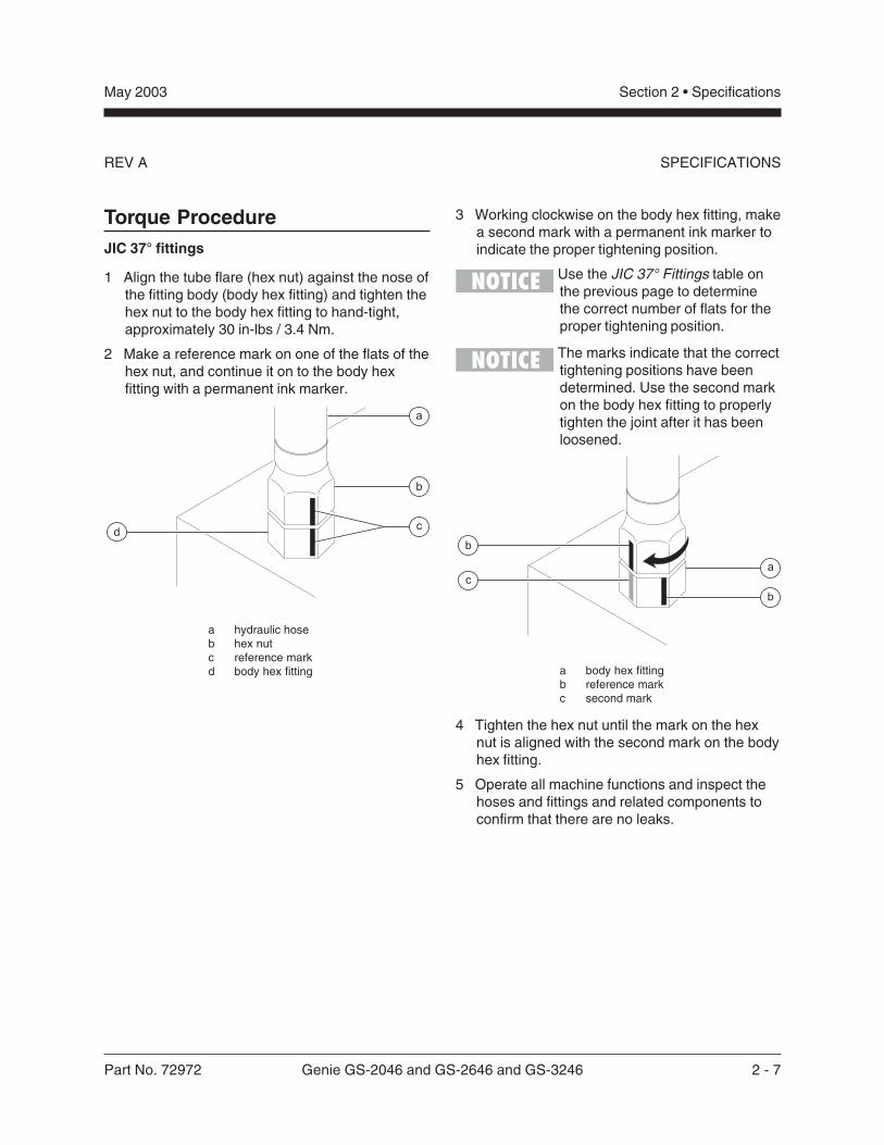
Torque ProcedureJIC 37° fittings
1 Align the tube flare (hex nut) against the nose ofthe fitting body (body hex fitting) and tighten thehex nut to the body hex fitting to hand-tight,approximately 30 in-lbs / 3.4 Nm.
2 Make a reference mark on one of the flats of thehex nut, and continue it on to the body hexfitting with a permanent ink marker.
a hydraulic hoseb hex nutc reference markd body hex fitting
3 Working clockwise on the body hex fitting, makea second mark with a permanent ink marker toindicate the proper tightening position.
Use the JIC 37° Fittings table onthe previous page to determinethe correct number of flats for theproper tightening position.
The marks indicate that the correcttightening positions have beendetermined. Use the second markon the body hex fitting to properlytighten the joint after it has beenloosened.
a body hex fittingb reference markc second mark
4 Tighten the hex nut until the mark on the hexnut is aligned with the second mark on the bodyhex fitting.
5 Operate all machine functions and inspect thehoses and fittings and related components toconfirm that there are no leaks.
b
c
a
d
a
b
c
b
SPECIFICATIONS
2 - 8 Genie GS-2046 and GS-2646 and GS-3246 Part No. 72972
Section 2 • Specifications May 2003
REV A
Seal-Lok® fittings
1 Replace the O-ring. The O-ring must bereplaced anytime the seal has been broken.The O-ring cannot be re-used if the fitting orhose end has been tightened beyond fingertight.
The O-rings used in the ParkerSeal Lok® fittings and hose endsare custom-size O-rings. They arenot standard SAE size O-rings.They are available in the O-ringfield service kit.
2 Lubricate the O-ring before installation.
3 Be sure that the face seal O-ring is seated andretained properly.
4 Position the tube and nut squarely on the faceseal end of the fitting and tighten the nut fingertight.
5 Tighten the nut or fitting to the appropriatetorque per given size as shown in the table.
6 Operate all machine functions and inspect thehoses and fittings and related components toconfirm that there are no leaks.
SPECIFICATIONS
Part No. 72972 Genie GS-2046 and GS-2646 and GS-3246 3 - 1
June 2003 Section 3 • Scheduled Maintenance Procedures
About This Section
This section contains detailed procedures for eachscheduled maintenance inspection.
Each procedure includes a description, safetywarnings and step-by-step instructions.
Symbols Legend
Safety alert symbol—used to alertpersonnel to potential personalinjury hazards. Obey all safetymessages that follow this symbolto avoid possible injury or death.
Red—used to indicate thepresence of an imminentlyhazardous situation which, if notavoided, will result in death orserious injury.
Orange—used to indicate thepresence of a potentiallyhazardous situation which, if notavoided, could result in death orserious injury.
Yellow with safety alert symbol—used to indicate the presence of apotentially hazardous situationwhich, if not avoided, may causeminor or moderate injury.
Yellow without safety alertsymbol—used to indicate thepresence of a potentiallyhazardous situation which, if notavoided, may result in propertydamage.
Green—used to indicate operationor maintenance information.
Indicates that a specific result is expected afterperforming a series of steps.
Scheduled Maintenance Procedures
Observe and Obey:
Maintenance inspections shall be completed bya person trained and qualified on themaintenance of this machine.
Scheduled maintenance inspections shall becompleted daily, quarterly, annually and every 2years as specified on the MaintenanceInspection Report.
Failure to properly complete eachinspection when required maycause death, serious injury orsubstantial machine damage.
Immediately tag and remove from service adamaged or malfunctioning machine.
Repair any machine damage or malfunctionbefore operating the machine.
Keep records on all inspections for three years.
Unless otherwise specified, perform eachprocedure with the machine in the followingconfiguration:
· Machine parked on a firm, level surface
· Platform in the stowed position
· Key switch in the off position with the keyremoved
· Wheels chocked
· All external AC power supply disconnectedfrom the machine
3 - 2 Genie GS-2046 and GS-2646 and GS-3246 Part No. 72972
June 2003Section 3 • Scheduled Maintenance Procedures
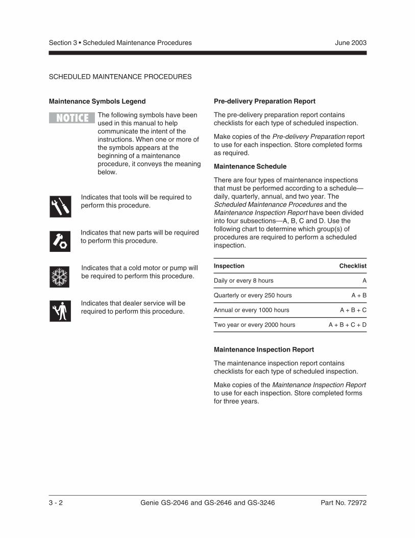
Maintenance Symbols Legend
The following symbols have beenused in this manual to helpcommunicate the intent of theinstructions. When one or more ofthe symbols appears at thebeginning of a maintenanceprocedure, it conveys the meaningbelow.
Indicates that tools will be required toperform this procedure.
Indicates that new parts will be requiredto perform this procedure.
Indicates that a cold motor or pump willbe required to perform this procedure.
Indicates that dealer service will berequired to perform this procedure.
Pre-delivery Preparation Report
The pre-delivery preparation report containschecklists for each type of scheduled inspection.
Make copies of the Pre-delivery Preparation reportto use for each inspection. Store completed formsas required.
Maintenance Schedule
There are four types of maintenance inspectionsthat must be performed according to a schedule—daily, quarterly, annual, and two year. TheScheduled Maintenance Procedures and theMaintenance Inspection Report have been dividedinto four subsections—A, B, C and D. Use thefollowing chart to determine which group(s) ofprocedures are required to perform a scheduledinspection.
Inspection Checklist
Daily or every 8 hours A
Quarterly or every 250 hours A + B
Annual or every 1000 hours A + B + C
Two year or every 2000 hours A + B + C + D
Maintenance Inspection Report
The maintenance inspection report containschecklists for each type of scheduled inspection.
Make copies of the Maintenance Inspection Reportto use for each inspection. Store completed formsfor three years.
SCHEDULED MAINTENANCE PROCEDURES
Part No. 72972 Genie GS-2046 and GS-2646 and GS-3246 3 - 3
June 2003 Section 3 • Scheduled Maintenance Procedures
Genie Industries USA18340 NE 76th StreetPO Box 97030Redmond, WA 98073-9730(425) 881-1800
Copyright © 2002 by Genie Industries. Genie® is a registered trademark of GenieIndustries. Rev A
Genie UKThe Maltings, Wharf Road
Grantham, LincolnshireNG31- 6BH England
(44) 1476-584333
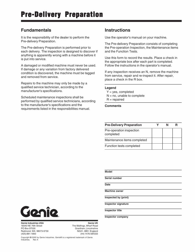
Pre-Delivery PreparationPre-Delivery PreparationPre-Delivery PreparationPre-Delivery PreparationPre-Delivery Preparation
Pre-Delivery Preparation Y N R
Pre-operation inspectioncompleted
Maintenance items completed
Function tests completed
Model
Serial number
Date
Machine owner
Inspected by (print)
Inspector signature
Inspector title
Inspector company
Instructions
Use the operator’s manual on your machine.
The Pre-delivery Preparation consists of completingthe Pre-operation Inspection, the Maintenance itemsand the Function Tests.
Use this form to record the results. Place a check inthe appropriate box after each part is completed.Follow the instructions in the operator’s manual.
If any inspection receives an N, remove the machinefrom service, repair and re-inspect it. After repair,place a check in the R box.
LegendY = yes, completedN = no, unable to completeR = repaired
Comments
Fundamentals
It is the responsibility of the dealer to perform thePre-delivery Preparation.
The Pre-delivery Preparation is performed prior toeach delivery. The inspection is designed to discover ifanything is apparently wrong with a machine before itis put into service.
A damaged or modified machine must never be used.If damage or any variation from factory deliveredcondition is discovered, the machine must be taggedand removed from service.
Repairs to the machine may only be made by aqualified service technician, according to themanufacturer's specifications.
Scheduled maintenance inspections shall beperformed by qualified service technicians, accordingto the manufacturer's specifications and therequirements listed in the responsibilities manual.

3 - 4 Genie GS-2046 and GS-2646 and GS-3246 Part No. 72972
June 2003Section 3 • Scheduled Maintenance Procedures
This page intentionally left blank.
Part No. 72972 Genie GS-2046 and GS-2646 and GS-3246 3 - 5
September 2006 Section 3 • Scheduled Maintenance Procedures
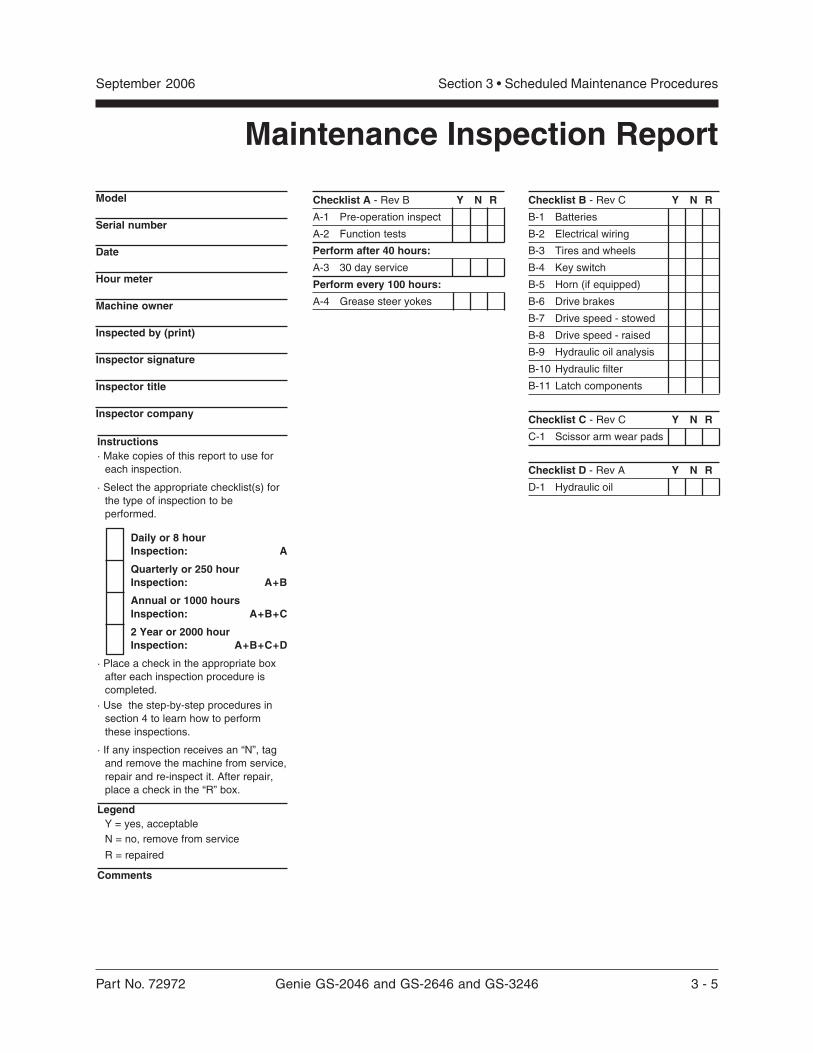
Maintenance Inspection Report
Instructions· Make copies of this report to use for
each inspection.
· Select the appropriate checklist(s) forthe type of inspection to beperformed.
Daily or 8 hourInspection: A
Quarterly or 250 hourInspection: A+B
Annual or 1000 hoursInspection: A+B+C
2 Year or 2000 hourInspection: A+B+C+D
· Place a check in the appropriate boxafter each inspection procedure iscompleted.
· Use the step-by-step procedures insection 4 to learn how to performthese inspections.
· If any inspection receives an “N”, tagand remove the machine from service,repair and re-inspect it. After repair,place a check in the “R” box.
LegendY = yes, acceptableN = no, remove from service
R = repaired
Comments
Model
Serial number
Date
Hour meter
Machine owner
Inspected by (print)
Inspector signature
Inspector title
Inspector company
Checklist B - Rev C Y N R
B-1 Batteries
B-2 Electrical wiring
B-3 Tires and wheels
B-4 Key switch
B-5 Horn (if equipped)
B-6 Drive brakes
B-7 Drive speed - stowed
B-8 Drive speed - raised
B-9 Hydraulic oil analysis
B-10 Hydraulic filter
B-11 Latch components
Checklist C - Rev C Y N R
C-1 Scissor arm wear pads
Checklist D - Rev A Y N R
D-1 Hydraulic oil
Checklist A - Rev B Y N R
A-1 Pre-operation inspect
A-2 Function tests
Perform after 40 hours:
A-3 30 day service
Perform every 100 hours:
A-4 Grease steer yokes
3 - 6 Genie GS-2046 and GS-2646 and GS-3246 Part No. 72972
June 2003Section 3 • Scheduled Maintenance Procedures
REV BChecklist A Procedures
A-1Perform Pre-operation InspectionCompleting a Pre-operation Inspection is essentialto safe machine operation. The Pre-operationInspection is a visual inspection performed by theoperator prior to each work shift. The inspection isdesigned to discover if anything is apparentlywrong with a machine before the operator performsthe function tests. The Pre-operation Inspectionalso serves to determine if routine maintenanceprocedures are required.
Complete information to perform this procedure isavailable in the Genie GS-1530 and GS-1532 andGS-1930 and GS-1932 Operator's Manual. Referto the Operator's Manual on your machine.
A-2Perform Function TestsCompleting the function tests is essential to safemachine operation. Function tests are designed todiscover any malfunctions before the machine isput into service. A malfunctioning machine mustnever be used. If malfunctions are discovered, themachine must be tagged and removed fromservice.
Complete information to perform this procedure isavailable in the Genie GS-1530 and GS-1532 andGS-1930 and GS-1932 Operator's Manual. Referto the Operator's Manual on your machine.
Part No. 72972 Genie GS-2046 and GS-2646 and GS-3246 3 - 7
June 2003 Section 3 • Scheduled Maintenance Procedures
REV B CHECKLIST A PROCEDURES
A-3Perform 30 Day Service
The 30 day maintenance procedure is a onetimeprocedure to be performed after the first 30 days or40 hours of usage. After this interval, refer to themaintenance tables for continued scheduledmaintenance.
1 Perform the following maintenance procedures:
· B-3 Inspect the Tires and Wheels(including castle nut torque)
· B-10 Replace the Hydraulic TankReturn Filter
A-4Grease the Steer Yokes
Genie specifications require thatthis procedure be performed every100 hours of operation.
Regular application of lubrication to the steer yokesis essential to good machine performance andservice life. Continued use of an insufficientlygreased steer yoke will result in componentdamage.
1 Locate the grease fitting on the top of the steeryoke.
2 Pump multipurpose grease into the steer yokeuntil the steer yoke is full and grease is beingforced past the bearings. Repeat this step forthe other steer yoke.
Grease type Multipurpose grease
3 - 8 Genie GS-2046 and GS-2646 and GS-3246 Part No. 72972
September 2006Section 3 • Scheduled Maintenance Procedures
REV C
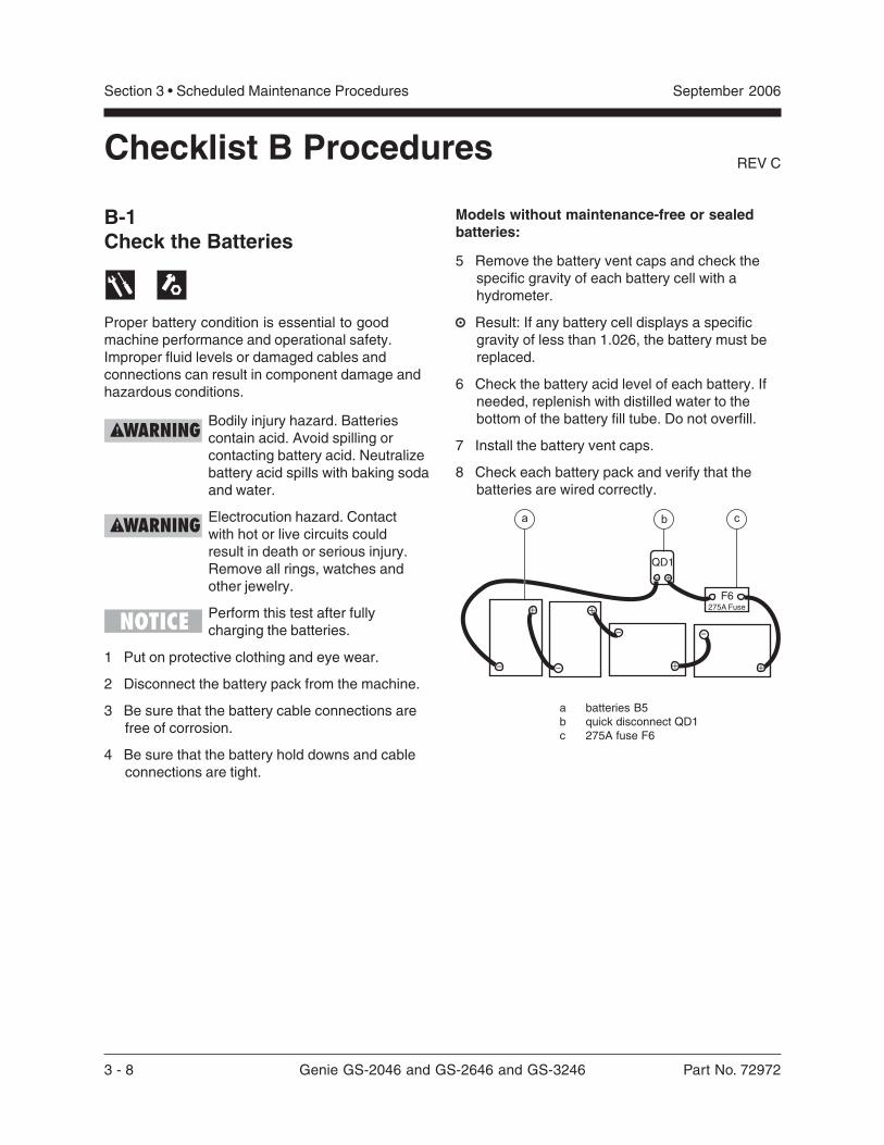
B-1Check the Batteries
Proper battery condition is essential to goodmachine performance and operational safety.Improper fluid levels or damaged cables andconnections can result in component damage andhazardous conditions.
Bodily injury hazard. Batteriescontain acid. Avoid spilling orcontacting battery acid. Neutralizebattery acid spills with baking sodaand water.
Electrocution hazard. Contactwith hot or live circuits couldresult in death or serious injury.Remove all rings, watches andother jewelry.
Perform this test after fullycharging the batteries.
1 Put on protective clothing and eye wear.
2 Disconnect the battery pack from the machine.
3 Be sure that the battery cable connections arefree of corrosion.
4 Be sure that the battery hold downs and cableconnections are tight.
Models without maintenance-free or sealedbatteries:
5 Remove the battery vent caps and check thespecific gravity of each battery cell with ahydrometer.
Result: If any battery cell displays a specificgravity of less than 1.026, the battery must bereplaced.
6 Check the battery acid level of each battery. Ifneeded, replenish with distilled water to thebottom of the battery fill tube. Do not overfill.
7 Install the battery vent caps.
8 Check each battery pack and verify that thebatteries are wired correctly.
Checklist B Procedures
F6
QD1
275A Fuse
+
-
+
-
-
+
+
- +
-
b ca
a batteries B5b quick disconnect QD1c 275A fuse F6
Part No. 72972 Genie GS-2046 and GS-2646 and GS-3246 3 - 9
September 2006 Section 3 • Scheduled Maintenance Procedures
REV C CHECKLIST B PROCEDURES
B-2Inspect the Electrical Wiring
Maintaining electrical wiring in good condition isessential to safe operation and good machineperformance. Failure to find and replace burnt,chafed, corroded or pinched wires could result inunsafe operating conditions and may causecomponent damage.
Electrocution hazard. Contact withhot or live circuits could result indeath or serious injury. Remove allrings, watches and other jewelry.
1 Inspect the underside of the chassis fordamaged or missing ground strap(s).
2 Inspect the following areas for burnt, chafed,corroded and loose wires:
· Ground control panel
· Hydraulic power unit module tray
· Battery pack module tray
· Scissor arms
· Platform controls
3 Inspect for a liberal coating of dielectric greasein all connections between the ECM and theplatform controls.
4 Turn the key switch to ground control and pullout the Emergency Stop button to the onposition at both the ground and platformcontrols.
5 Raise the platform approximately 8 feet / 2.4 mfrom the ground.
6 Rotate the safety arm away from the machineand let it hang down.
7 Lower the platform onto the safety arm.
Crushing hazard. Keep handsclear of the safety arm whenlowering the platform.
8 Inspect the center chassis area and scissorarms for burnt, chafed and pinched cables.
9 Inspect the following areas for burnt, chafed,corroded, pinched and loose wires:
· Scissor arms
· ECM to platform controls
· Power to platform wiring
10 Inspect for a liberal coating of dielectric greasein all connections between the ECM and theplatform controls.
11 Raise the platform and return the safety arm tothe stowed position.
12 Lower the platform to the stowed position andturn the machine off.
3 - 10 Genie GS-2046 and GS-2646 and GS-3246 Part No. 72972
September 2006Section 3 • Scheduled Maintenance Procedures
REV C
B-3Inspect the Tires and Wheels(including castle nut torque)
Maintaining the tires and wheels in goodcondition is essential to safe operation and goodperformance. Tire and/or wheel failure could resultin a machine tip-over. Component damage mayalso result if problems are not discovered andrepaired in a timely fashion.
1 Check the tire surface and sidewalls for cuts,cracks or unusual wear.
2 Check each wheel for damage, bends andcracks.
3 Remove the cotter pin and check each castlenut for proper torque. Refer to Section 2,Specifications.
Always replace the cotter pin witha new one when removing thecastle nut or when checking thetorque of the castle nut.
4 Install a new cotter pin. Bend the cotter pin tolock it in place.
CHECKLIST B PROCEDURES
B-4Test the Key SwitchProper key switch action and response is essentialto safe machine operation. The machine can beoperated from the ground or platform controls andthe activation of one or the other is accomplishedwith the key switch. Failure of the key switch toactivate the appropriate control panel could causea hazardous operating situation.
Perform this procedure from theground using the platform controls.Do not stand in the platform.
1 Pull out the Emergency Stop button to the onposition at both the ground and platformcontrols.
2 Turn the key switch to platform control.
3 Check the platform up/down function from theground controls.
Result: The machine functions should notoperate.
4 Turn the key switch to ground control.
5 Check the machine functions from the platformcontrols.
Result: The machine functions should notoperate.
6 Turn the key switch to the off position.
Result: No machine functions should operate.
Part No. 72972 Genie GS-2046 and GS-2646 and GS-3246 3 - 11
September 2006 Section 3 • Scheduled Maintenance Procedures
REV C
B-5Test the Automotive-style Horn(if equipped)A functioning horn is essential to safe machineoperation. The horn is activated at the platformcontrols and sounds at the ground as a warning toground personnel. An improperly functioning hornwill prevent the operator from alerting groundpersonnel of hazards or unsafe conditions.
1 Turn the key switch to platform control andpull out the Emergency Stop button to theon position at both the ground andplatform controls.
2 Push down the horn button at the platformcontrols.
Result: The horn should sound.
CHECKLIST B PROCEDURES
3 - 12 Genie GS-2046 and GS-2646 and GS-3246 Part No. 72972
September 2006Section 3 • Scheduled Maintenance Procedures
REV C
B-6Test the Drive Brakes
Proper brake action is essential to safe machineoperation. The drive brake function should operatesmoothly, free of hesitation, jerking and unusualnoise. Hydraulically-released individual wheelbrakes can appear to operate normally when notfully operational.
Perform this procedure with themachine on a flat, level surfacethat is free of obstructions.
Be sure the platform extensiondeck is fully retracted and theplatform is in the stowed position.
1 Mark a test line on the ground for reference.
2 Turn the key switch to platform control and pullout the Emergency Stop button to the onposition at both the ground and platformcontrols.
2 Lower the platform to the stowed position.
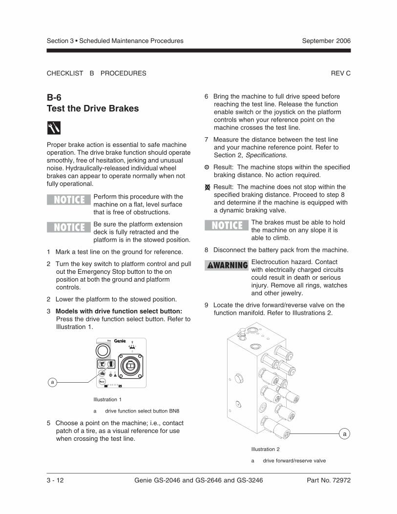
3 Models with drive function select button:Press the drive function select button. Refer toIllustration 1.
®
Stop
a
Illustration 1
a drive function select button BN8
5 Choose a point on the machine; i.e., contactpatch of a tire, as a visual reference for usewhen crossing the test line.
6 Bring the machine to full drive speed beforereaching the test line. Release the functionenable switch or the joystick on the platformcontrols when your reference point on themachine crosses the test line.
7 Measure the distance between the test lineand your machine reference point. Refer toSection 2, Specifications.
Result: The machine stops within the specifiedbraking distance. No action required.
Result: The machine does not stop within thespecified braking distance. Proceed to step 8and determine if the machine is equipped witha dynamic braking valve.
The brakes must be able to holdthe machine on any slope it isable to climb.
8 Disconnect the battery pack from the machine.
Electrocution hazard. Contactwith electrically charged circuitscould result in death or seriousinjury. Remove all rings, watchesand other jewelry.
9 Locate the drive forward/reverse valve on thefunction manifold. Refer to Illustrations 2.
CHECKLIST B PROCEDURES
Illustration 2
a drive forward/reserve valve
a
Part No. 72972 Genie GS-2046 and GS-2646 and GS-3246 3 - 13
September 2006 Section 3 • Scheduled Maintenance Procedures
REV C
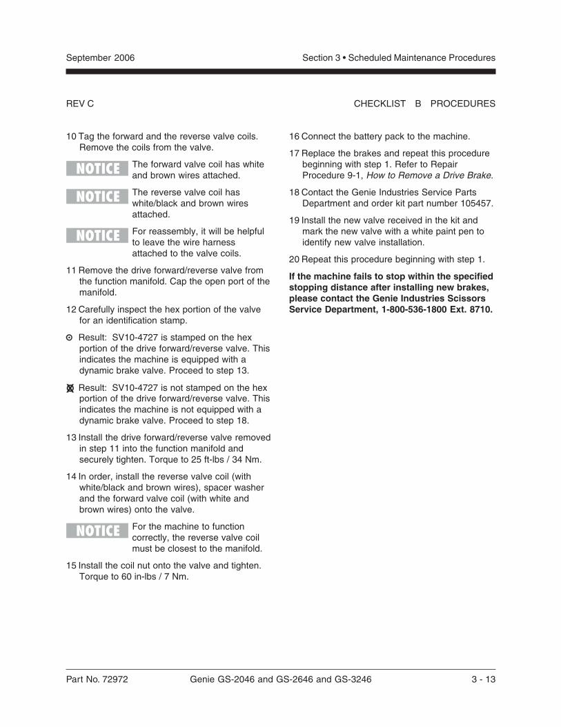
10 Tag the forward and the reverse valve coils.Remove the coils from the valve.
The forward valve coil has whiteand brown wires attached.
The reverse valve coil haswhite/black and brown wiresattached.
For reassembly, it will be helpfulto leave the wire harnessattached to the valve coils.
11 Remove the drive forward/reverse valve fromthe function manifold. Cap the open port of themanifold.
12 Carefully inspect the hex portion of the valvefor an identification stamp.
Result: SV10-4727 is stamped on the hexportion of the drive forward/reverse valve. Thisindicates the machine is equipped with adynamic brake valve. Proceed to step 13.
Result: SV10-4727 is not stamped on the hexportion of the drive forward/reverse valve. Thisindicates the machine is not equipped with adynamic brake valve. Proceed to step 18.
13 Install the drive forward/reverse valve removedin step 11 into the function manifold andsecurely tighten. Torque to 25 ft-lbs / 34 Nm.
14 In order, install the reverse valve coil (withwhite/black and brown wires), spacer washerand the forward valve coil (with white andbrown wires) onto the valve.
For the machine to functioncorrectly, the reverse valve coilmust be closest to the manifold.
15 Install the coil nut onto the valve and tighten.Torque to 60 in-lbs / 7 Nm.
16 Connect the battery pack to the machine.
17 Replace the brakes and repeat this procedurebeginning with step 1. Refer to RepairProcedure 9-1, How to Remove a Drive Brake.
18 Contact the Genie Industries Service PartsDepartment and order kit part number 105457.
19 Install the new valve received in the kit andmark the new valve with a white paint pen toidentify new valve installation.
20 Repeat this procedure beginning with step 1.
If the machine fails to stop within the specifiedstopping distance after installing new brakes,please contact the Genie Industries ScissorsService Department, 1-800-536-1800 Ext. 8710.
CHECKLIST B PROCEDURES
3 - 14 Genie GS-2046 and GS-2646 and GS-3246 Part No. 72972
September 2006Section 3 • Scheduled Maintenance Procedures
REV CCHECKLIST B PROCEDURES
®
Stop
a
B-7Test the Drive Speed -Stowed Position
Proper drive functions are essential to safemachine operation. The drive function shouldrespond quickly and smoothly to operator control.Drive performance should also be free ofhesitation, jerking and unusual noise over theentire proportionally controlled speed range.
Perform this procedure with themachine on a firm, level surfacethat is free of obstructions.
1 Create start and finish lines by marking twolines on the ground 40 feet / 12.2 m apart.
2 Turn the key switch to platform control and pullout the Emergency Stop button to the onposition at both the ground and platformcontrols.
3 Lower the platform to the stowed position.
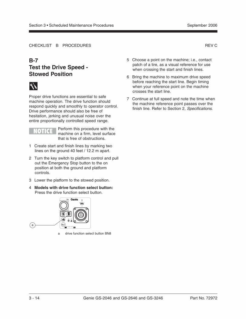
4 Models with drive function select button:Press the drive function select button.
a drive function select button BN8
5 Choose a point on the machine; i.e., contactpatch of a tire, as a visual reference for usewhen crossing the start and finish lines.
6 Bring the machine to maximum drive speedbefore reaching the start line. Begin timingwhen your reference point on the machinecrosses the start line.
7 Continue at full speed and note the time whenthe machine reference point passes over thefinish line. Refer to Section 2, Specifications.
Part No. 72972 Genie GS-2046 and GS-2646 and GS-3246 3 - 15
September 2006 Section 3 • Scheduled Maintenance Procedures
REV C CHECKLIST B PROCEDURES
®
Stop
®
Stop
a
b
c
B-8Test the Drive Speed -Raised Position
Proper drive functions are essential to safemachine operation. The drive function shouldrespond quickly and smoothly to operator control.Drive performance should also be free ofhesitation, jerking and unusual noise over theentire proportionally controlled speed range.
Perform this procedure with themachine on a firm, level surfacethat is free of obstructions.
1 Create start and finish lines by marking twolines on the ground 40 feet / 12.2 m apart.
2 Turn the key switch to platform control and pullout the Emergency Stop button to the onposition at both the ground and platformcontrols.
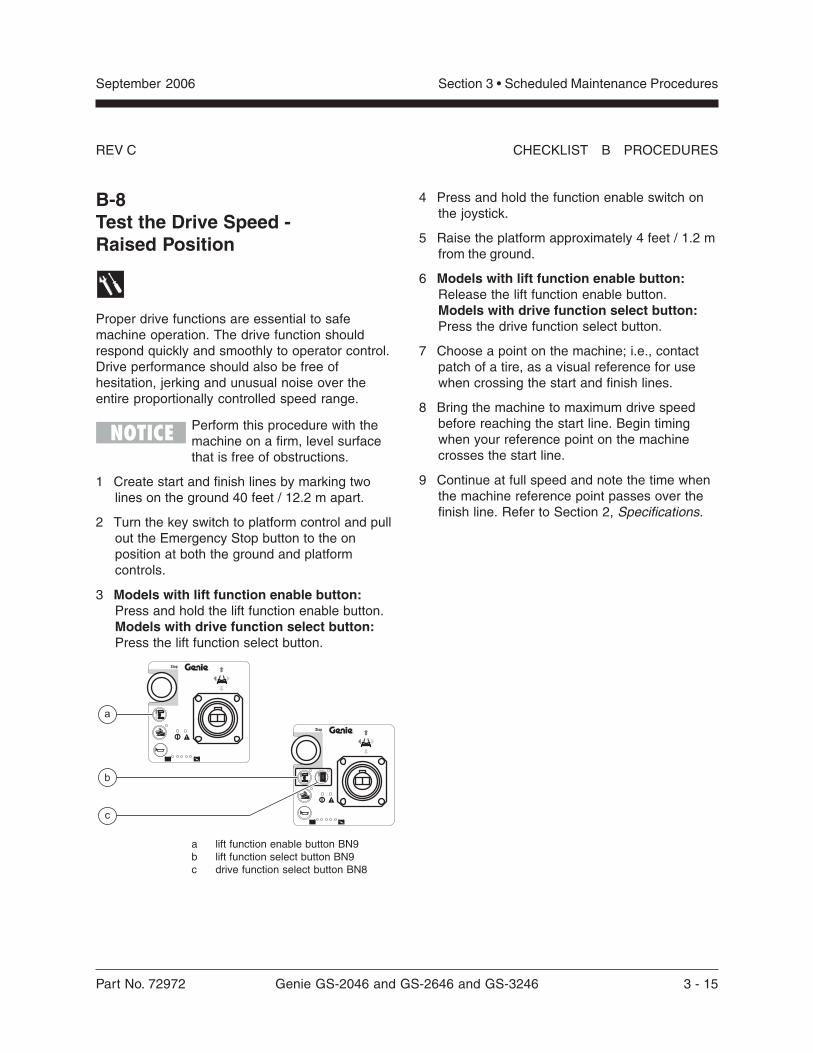
3 Models with lift function enable button:Press and hold the lift function enable button.Models with drive function select button:Press the lift function select button.
a lift function enable button BN9b lift function select button BN9c drive function select button BN8
4 Press and hold the function enable switch onthe joystick.
5 Raise the platform approximately 4 feet / 1.2 mfrom the ground.
6 Models with lift function enable button:Release the lift function enable button.Models with drive function select button:Press the drive function select button.
7 Choose a point on the machine; i.e., contactpatch of a tire, as a visual reference for usewhen crossing the start and finish lines.
8 Bring the machine to maximum drive speedbefore reaching the start line. Begin timingwhen your reference point on the machinecrosses the start line.
9 Continue at full speed and note the time whenthe machine reference point passes over thefinish line. Refer to Section 2, Specifications.
3 - 16 Genie GS-2046 and GS-2646 and GS-3246 Part No. 72972
September 2006Section 3 • Scheduled Maintenance Procedures
REV CCHECKLIST B PROCEDURES
B-9Perform Hydraulic Oil Analysis
Replacement or testing of the hydraulic oil isessential for good machine performance andservice life. Dirty oil and a clogged suction strainermay cause the machine to perform poorly andcontinued use may cause component damage.Extremely dirty conditions may require oilchanges to be performed more often.
Before replacing the hydraulic oil,the oil may be tested by an oildistributor for specific levels ofcontamination to verify thatchanging the oil is necessary. Ifthe hydraulic oil is not replacedat the two year inspection, testthe oil quarterly. Replace the oilwhen it fails the test. See D-1,Test or Replace the Hydraulic Oil.
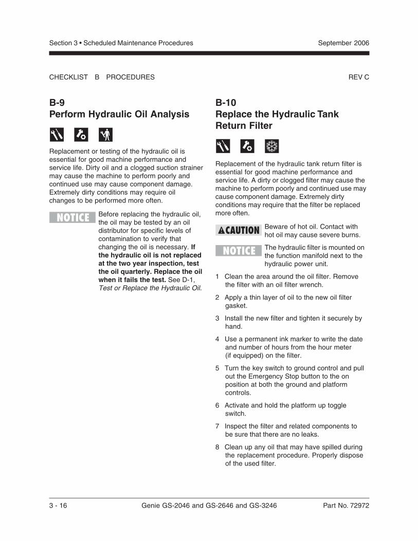
B-10Replace the Hydraulic TankReturn Filter
Replacement of the hydraulic tank return filter isessential for good machine performance andservice life. A dirty or clogged filter may cause themachine to perform poorly and continued use maycause component damage. Extremely dirtyconditions may require that the filter be replacedmore often.
Beware of hot oil. Contact withhot oil may cause severe burns.
The hydraulic filter is mounted onthe function manifold next to thehydraulic power unit.
1 Clean the area around the oil filter. Removethe filter with an oil filter wrench.
2 Apply a thin layer of oil to the new oil filtergasket.
3 Install the new filter and tighten it securely byhand.
4 Use a permanent ink marker to write the dateand number of hours from the hour meter(if equipped) on the filter.
5 Turn the key switch to ground control and pullout the Emergency Stop button to the onposition at both the ground and platformcontrols.
6 Activate and hold the platform up toggleswitch.
7 Inspect the filter and related components tobe sure that there are no leaks.
8 Clean up any oil that may have spilled duringthe replacement procedure. Properly disposeof the used filter.
Part No. 72972 Genie GS-2046 and GS-2646 and GS-3246 3 - 17
September 2006 Section 3 • Scheduled Maintenance Procedures
REV C CHECKLIST B PROCEDURES
b
a
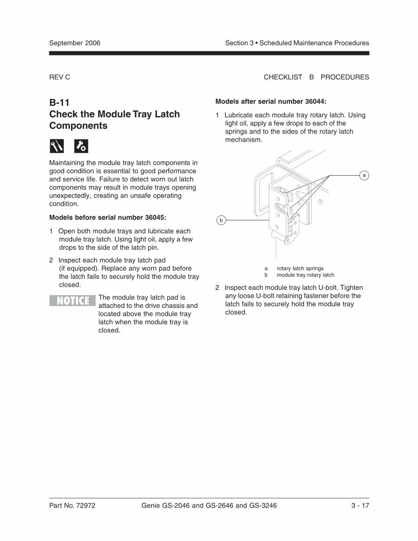
B-11Check the Module Tray LatchComponents
Maintaining the module tray latch components ingood condition is essential to good performanceand service life. Failure to detect worn out latchcomponents may result in module trays openingunexpectedly, creating an unsafe operatingcondition.
Models before serial number 36045:
1 Open both module trays and lubricate eachmodule tray latch. Using light oil, apply a fewdrops to the side of the latch pin.
2 Inspect each module tray latch pad(if equipped). Replace any worn pad beforethe latch fails to securely hold the module trayclosed.
The module tray latch pad isattached to the drive chassis andlocated above the module traylatch when the module tray isclosed.
Models after serial number 36044:
1 Lubricate each module tray rotary latch. Usinglight oil, apply a few drops to each of thesprings and to the sides of the rotary latchmechanism.
a rotary latch springsb module tray rotary latch
2 Inspect each module tray latch U-bolt. Tightenany loose U-bolt retaining fastener before thelatch fails to securely hold the module trayclosed.
3 - 18 Genie GS-2046 and GS-2646 and GS-3246 Part No. 72972
June 2003Section 3 • Scheduled Maintenance Procedures
This page intentionally left blank.
Part No. 72972 Genie GS-2046 and GS-2646 and GS-3246 3 - 19
June 2006 Section 3 • Scheduled Maintenance Procedures
REV C
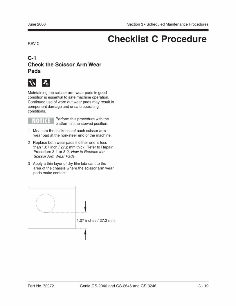
C-1Check the Scissor Arm WearPads
Maintaining the scissor arm wear pads in goodcondition is essential to safe machine operation.Continued use of worn out wear pads may result incomponent damage and unsafe operatingconditions.
Perform this procedure with theplatform in the stowed position.
1 Measure the thickness of each scissor armwear pad at the non-steer end of the machine.
2 Replace both wear pads if either one is lessthan 1.07 inch / 27.2 mm thick. Refer to RepairProcedure 3-1 or 3-2, How to Replace theScissor Arm Wear Pads.
3 Apply a thin layer of dry film lubricant to thearea of the chassis where the scissor arm wearpads make contact.
Checklist C Procedure
1.07 inches / 27.2 mm
3 - 20 Genie GS-2046 and GS-2646 and GS-3246 Part No. 72972
June 2003Section 3 • Scheduled Maintenance Procedures
REV A
D-1Test or Replace the Hydraulic Oil
Replacement or testing of the hydraulic oil isessential for good machine performance andservice life. Dirty oil and a clogged suction strainermay cause the machine to perform poorly andcontinued use may cause component damage.Extremely dirty conditions may require oil changesto be performed more often.
Before replacing the hydraulic oil,the oil may be tested by an oildistributor for specific levels ofcontamination to verify thatchanging the oil is necessary. Ifthe hydraulic oil is not replacedat the two year inspection, testthe oil quarterly. Replace the oilwhen it fails the test.
Perform this procedure with theplatform in the stowed position.
1 Disconnect the battery pack from the machine.
2 Open the power unit module tray. Remove thedrain plug from the hydraulic tank and allow allof the oil to drain into a suitable container. Referto Section 2, Specifications, for capacityinformation.
Bodily injury hazard. Sprayinghydraulic oil can penetrate andburn skin. Loosen hydraulicconnections very slowly to allowthe oil pressure to dissipategradually. Do not allow oil to squirtor spray.
3 Tag, disconnect and cap the hydraulic hosesfrom the hydraulic tank.
4 Remove the hydraulic tank mounting fasteners.Remove the hydraulic tank from the machine.
Checklist D Procedure
5 Remove the suction strainer and clean it usinga mild solvent.
6 Clean the inside of the hydraulic tank using amild solvent.
7 Install the suction strainer using thread sealeron the threads.
8 Install the drain plug using thread sealer on thethreads. Torque to specification.
Torque specifications
Hydraulic tank drain plug, dry 75 in-lbs8.5 Nm
Hydraulic tank drain plug, lubricated 56 in-lbs6.3 Nm
9 Install the hydraulic tank and install and tightenthe hydraulic tank retaining fasteners. Torque tospecification.
Torque specifications
Hydraulic tank retaining fasteners, dry 70 in-lbs7.9 Nm
Hydraulic tank retaining fasteners, lubricated 52 in-lbs5.9 Nm
10 Connect the hydraulic hoses to the hydraulictank.
11 Fill the tank with hydraulic oil until the fluid iswithin the FULL and ADD marks on the oil levelindicator decal. Do not overfill.
12 Activate the pump to fill the hydraulic systemwith oil and bleed the system of air and checkfor leaks.
13 Repeat steps 11 and 12 until the hydraulic tankand system are both full.
14 Clean up any oil that may have spilled. Properlydiscard the used oil.
Part No. 72972 Genie GS-2046 and GS-2646 and GS-3246 4 - 1
June 2003 Section 4 • Repair Procedures
Repair Procedures
Observe and Obey:
Repair procedures shall be completed by aperson trained and qualified on the repair of thismachine.
Immediately tag and remove from service adamaged or malfunctioning machine.
Repair any machine damage or malfunctionbefore operating the machine.
Before Repairs Start:
Read, understand and obey the safety rulesand operating instructions in the GenieGS-2032 and GS-2632 and GS-2046 andGS-2646 and GS-3246 Operator's Manual.
Be sure that all necessary tools and parts areavailable and ready for use.
Read each procedure completely and adhere tothe instructions. Attempting shortcuts mayproduce hazardous conditions.
Unless otherwise specified, perform each repairprocedure with the machine in the followingconfiguration:
· Machine parked on a firm, level surface
· Platform in the stowed position
· Key switch in the off position with the keyremoved
· Wheels chocked
· All external AC power supply disconnectedfrom the machine
About This Section
Most of the procedures in this section should onlybe performed by a trained service professionalin a suitably equipped workshop. Select theappropriate repair procedure after troubleshootingthe problem.
Perform disassembly procedures to the pointwhere repairs can be completed. Then tore-assemble, perform the disassembly steps inreverse order.
Symbols Legend
Safety alert symbol—used to alertpersonnel to potential personalinjury hazards. Obey all safetymessages that follow this symbolto avoid possible injury or death.
Red—used to indicate thepresence of an imminentlyhazardous situation which, if notavoided, will result in death orserious injury.
Orange—used to indicate thepresence of a potentiallyhazardous situation which, if notavoided, could result in death orserious injury.
Yellow with safety alert symbol—used to indicate the presence of apotentially hazardous situationwhich, if not avoided, may causeminor or moderate injury.
Yellow without safety alertsymbol—used to indicate thepresence of a potentiallyhazardous situation which, if notavoided, may result in propertydamage.
Green—used to indicate operationor maintenance information.
Indicates that a specific result is expected afterperforming a series of steps.
4 - 2 Genie GS-2046 and GS-2646 and GS-3246 Part No. 72972
June 2003Section 4 • Repair Procedures
REV BPlatform Controls
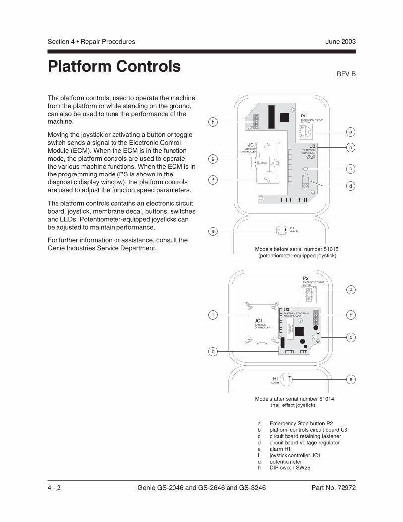
The platform controls, used to operate the machinefrom the platform or while standing on the ground,can also be used to tune the performance of themachine.
Moving the joystick or activating a button or toggleswitch sends a signal to the Electronic ControlModule (ECM). When the ECM is in the functionmode, the platform controls are used to operatethe various machine functions. When the ECM is inthe programming mode (PS is shown in thediagnostic display window), the platform controlsare used to adjust the function speed parameters.
The platform controls contains an electronic circuitboard, joystick, membrane decal, buttons, switchesand LEDs. Potentiometer-equipped joysticks canbe adjusted to maintain performance.
For further information or assistance, consult theGenie Industries Service Department.
P2EMERGENCY STOPBUTTON
JC1JOYSTICK
CONTROLLER
H1ALARM
21
U3PLATFORMCONTROLS
CIRCUITBOARD
h
g
f
e
a
b
c
d
19
F2
34
56
78
ON
AL
CO
AD
F0
85
P2EMERGENCY STOPBUTTON
H1ALARM
U3PLATFORM CONTROLSCIRCUIT BOARD
14.25.
2
1 NC
19
F2
34
56
78
ON
AL
CO
AD
F0
85
P/N
00
00
00
Da
te0
00
0
S/N
Al0
00
00
00
0
JC1JOYSTICKCONTROLLER
h
a
c
e
f
b
Models after serial number 51014 (hall effect joystick)
a Emergency Stop button P2b platform controls circuit board U3c circuit board retaining fastenerd circuit board voltage regulatore alarm H1f joystick controller JC1g potentiometerh DIP switch SW25
Models before serial number 51015 (potentiometer-equipped joystick)
Part No. 72972 Genie GS-2046 and GS-2646 and GS-3246 4 - 3
June 2003 Section 4 • Repair Procedures
REV B
1-1Circuit Boards
How to Remove the PlatformControls Circuit Board1 Push in the Emergency Stop button to the off
position at both the ground and platformcontrols.
2 Loosen the platform control box lid retainingfasteners. Open the control box lid.
3 Locate the circuit board mounted to the insideof the platform control box lid.
Electrocution hazard. Contact withelectrically charged circuits couldresult in death or serious injury.Remove all rings, watches andother jewelry.
Component damage hazard.Electrostatic discharge (ESD) candamage printed circuit boardcomponents. Maintain firm contactwith a metal part of the machinethat is grounded at all times whenhandling printed circuit boards ORuse a grounded wrist strap.
4 Carefully disconnect the three wire harnessconnectors from the platform controls circuitboard.
5 Carefully remove the platform controls circuitboard retaining fasteners.
6 Carefully remove the platform controls circuitboard from the platform control box lid.
1-2Joystick Controller
Maintaining the joystick at the proper setting isessential to safe machine operation. The joystickshould operate smoothly over its entire range ofmotion.
A Hall-effect joystick controller was incorporatedinto the platform controls after serial number48054. It does not require any calibration.
How to Calibrate the JoystickController(before serial number 48055)
This procedure applies onlyto models with apotentiometer-equipped joystick.
1 Turn the key switch to platform controls and pullout the Emergency Stop button to the onposition at both the ground and platformcontrols.
2 Remove the platform control box lid retainingfasteners. Open the control box lid.
Electrocution hazard. Contact withelectrically charged circuits couldresult in death or serious injury.Remove all rings, watches andother jewelry.
PLATFORM CONTROLS
4 - 4 Genie GS-2046 and GS-2646 and GS-3246 Part No. 72972
June 2003Section 4 • Repair Procedures
REV BPLATFORM CONTROLS
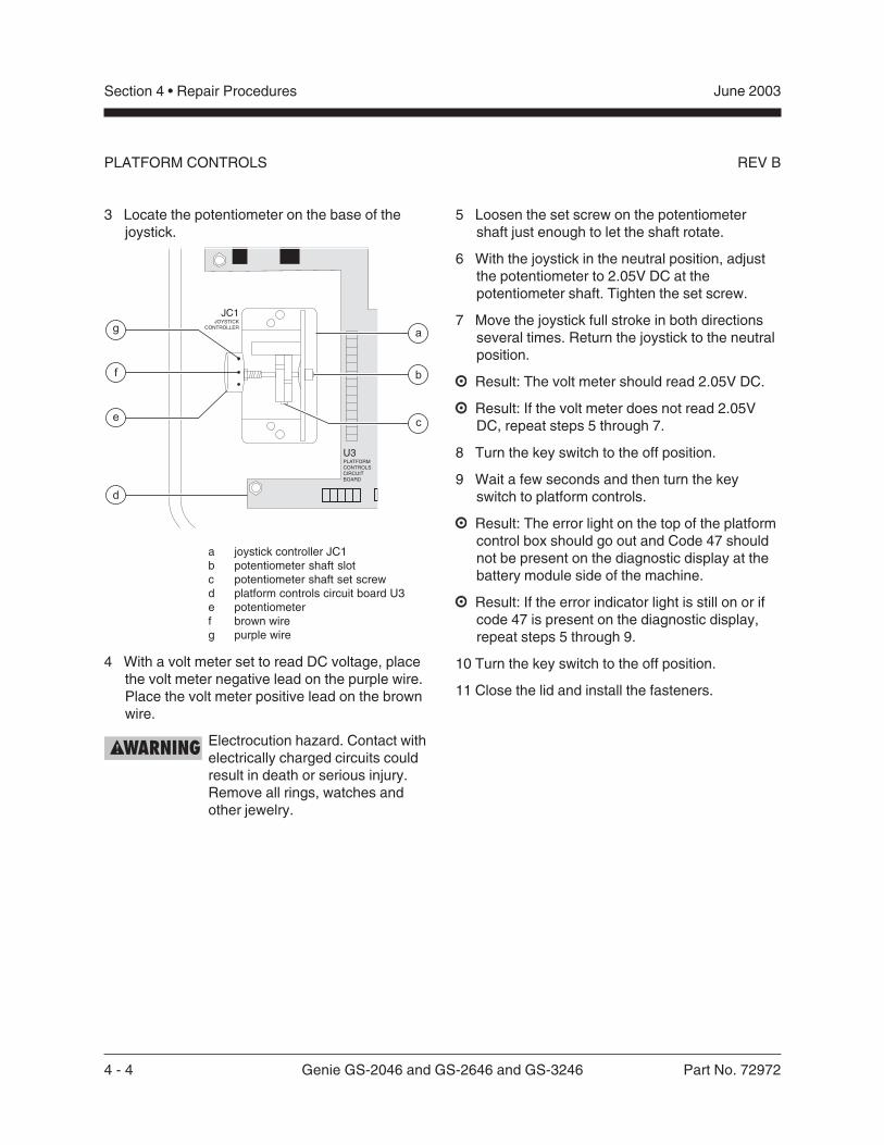
3 Locate the potentiometer on the base of thejoystick.
a joystick controller JC1b potentiometer shaft slotc potentiometer shaft set screwd platform controls circuit board U3e potentiometerf brown wireg purple wire
4 With a volt meter set to read DC voltage, placethe volt meter negative lead on the purple wire.Place the volt meter positive lead on the brownwire.
Electrocution hazard. Contact withelectrically charged circuits couldresult in death or serious injury.Remove all rings, watches andother jewelry.
5 Loosen the set screw on the potentiometershaft just enough to let the shaft rotate.
6 With the joystick in the neutral position, adjustthe potentiometer to 2.05V DC at thepotentiometer shaft. Tighten the set screw.
7 Move the joystick full stroke in both directionsseveral times. Return the joystick to the neutralposition.
Result: The volt meter should read 2.05V DC.
Result: If the volt meter does not read 2.05VDC, repeat steps 5 through 7.
8 Turn the key switch to the off position.
9 Wait a few seconds and then turn the keyswitch to platform controls.
Result: The error light on the top of the platformcontrol box should go out and Code 47 shouldnot be present on the diagnostic display at thebattery module side of the machine.
Result: If the error indicator light is still on or ifcode 47 is present on the diagnostic display,repeat steps 5 through 9.
10 Turn the key switch to the off position.
11 Close the lid and install the fasteners.
Part No. 72972 Genie GS-2046 and GS-2646 and GS-3246 4 - 5
June 2003 Section 4 • Repair Procedures
REV B PLATFORM CONTROLS
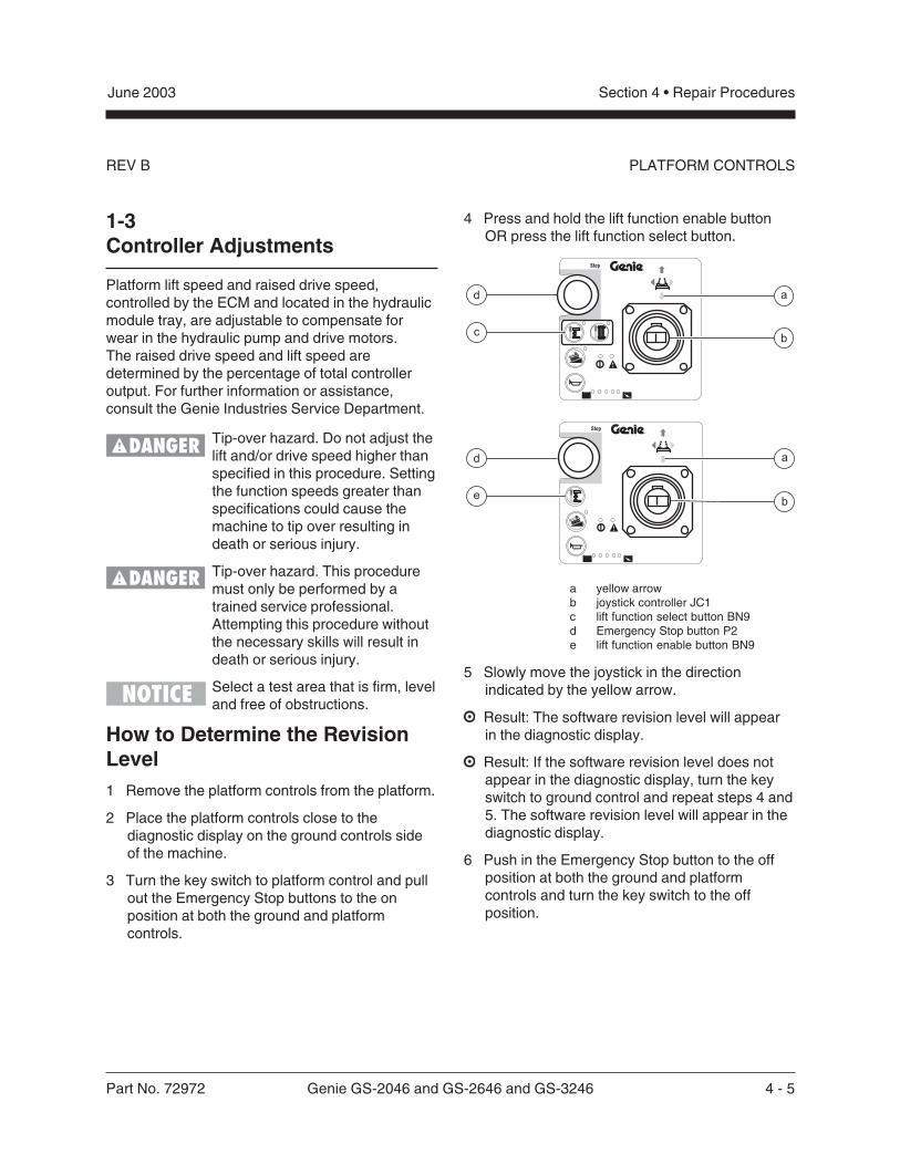
4 Press and hold the lift function enable buttonOR press the lift function select button.
a yellow arrowb joystick controller JC1c lift function select button BN9d Emergency Stop button P2e lift function enable button BN9
5 Slowly move the joystick in the directionindicated by the yellow arrow.
Result: The software revision level will appearin the diagnostic display.
Result: If the software revision level does notappear in the diagnostic display, turn the keyswitch to ground control and repeat steps 4 and5. The software revision level will appear in thediagnostic display.
6 Push in the Emergency Stop button to the offposition at both the ground and platformcontrols and turn the key switch to the offposition.
1-3Controller Adjustments
Platform lift speed and raised drive speed,controlled by the ECM and located in the hydraulicmodule tray, are adjustable to compensate forwear in the hydraulic pump and drive motors.The raised drive speed and lift speed aredetermined by the percentage of total controlleroutput. For further information or assistance,consult the Genie Industries Service Department.
Tip-over hazard. Do not adjust thelift and/or drive speed higher thanspecified in this procedure. Settingthe function speeds greater thanspecifications could cause themachine to tip over resulting indeath or serious injury.
Tip-over hazard. This proceduremust only be performed by atrained service professional.Attempting this procedure withoutthe necessary skills will result indeath or serious injury.
Select a test area that is firm, leveland free of obstructions.
How to Determine the RevisionLevel1 Remove the platform controls from the platform.
2 Place the platform controls close to thediagnostic display on the ground controls sideof the machine.
3 Turn the key switch to platform control and pullout the Emergency Stop buttons to the onposition at both the ground and platformcontrols.
4 - 6 Genie GS-2046 and GS-2646 and GS-3246 Part No. 72972
June 2003Section 4 • Repair Procedures
REV BPLATFORM CONTROLS
How to Adjust the Lift SpeedTip-over hazard. Do not adjust thelift and/or drive speed higher thanspecified in this procedure. Settingthe drive speed greater thanspecifications will cause death orserious injury.
Tip-over hazard. This proceduremust only be performed by atrained service professional.Attempting this procedure withoutthe necessary skills will result indeath or serious injury.
Software revision A0 and B0:
1 Push in the Emergency Stop button to the offposition at the ground and platform controls.Turn the key switch to the off position.
2 Pull out the Emergency Stop button to the onposition at the ground and platform controls.
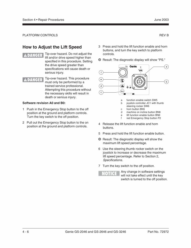
3 Press and hold the lift function enable and hornbuttons, and turn the key switch to platformcontrols.
Result: The diagnostic display will show "PS."
a function enable switch SW5b joystick controller JC1 with thumb
steering rocker SW6c horn button BN5d machine on incline button BN6e lift function enable button BN9f red Emergency Stop button P2
4 Release the lift function enable and hornbuttons.
5 Press and hold the lift function enable button.
Result: The diagnostic display will show themaximum lift speed percentage.
6 Use the steering thumb rocker switch on thejoystick to increase or decrease the maximumlift speed percentage. Refer to Section 2,Specifications.
7 Turn the key switch to the off position.
Any change in software settingswill not take effect until the keyswitch is turned to the off position.
Part No. 72972 Genie GS-2046 and GS-2646 and GS-3246 4 - 7
June 2003 Section 4 • Repair Procedures
REV B PLATFORM CONTROLS
Software revision C0 and higher:
1 Push in the red Emergency Stop button to theoff position at the ground and platform controls.Turn the key switch to the off position.
2 Pull out the red Emergency Stop button to theon position at the ground and platform controls.
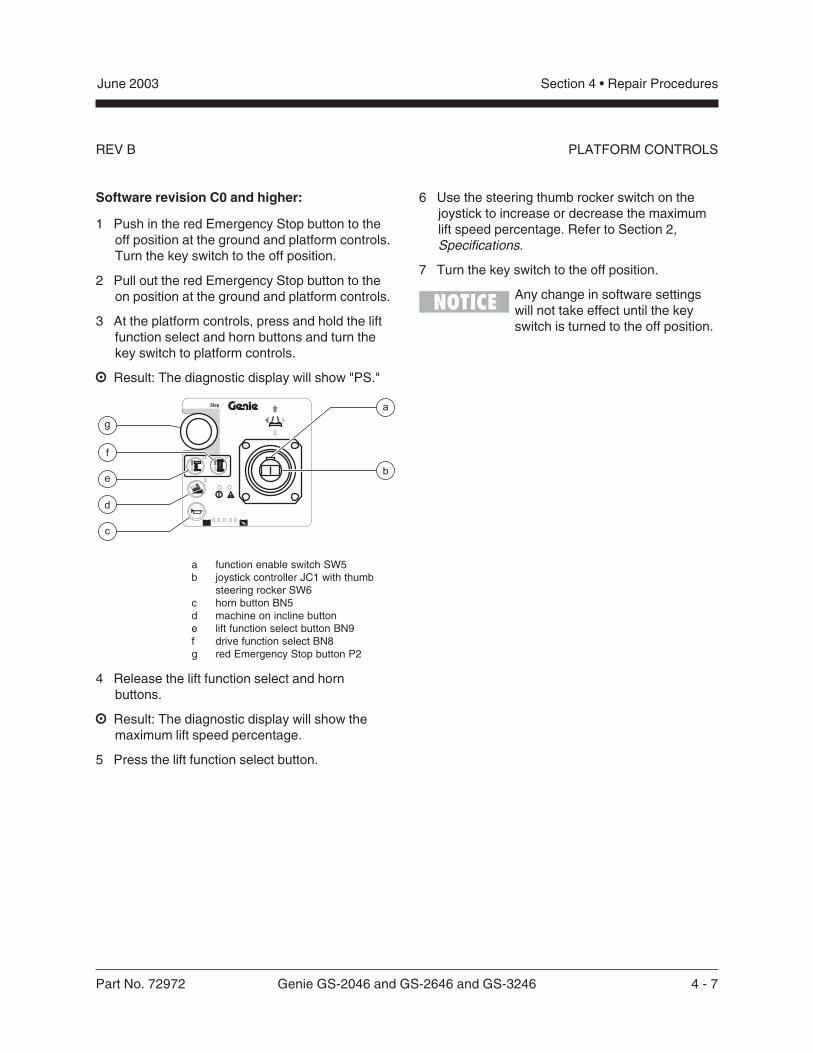
3 At the platform controls, press and hold the liftfunction select and horn buttons and turn thekey switch to platform controls.
Result: The diagnostic display will show "PS."
a function enable switch SW5b joystick controller JC1 with thumb
steering rocker SW6c horn button BN5d machine on incline buttone lift function select button BN9f drive function select BN8g red Emergency Stop button P2
4 Release the lift function select and hornbuttons.
Result: The diagnostic display will show themaximum lift speed percentage.
5 Press the lift function select button.
6 Use the steering thumb rocker switch on thejoystick to increase or decrease the maximumlift speed percentage. Refer to Section 2,Specifications.
7 Turn the key switch to the off position.
Any change in software settingswill not take effect until the keyswitch is turned to the off position.
4 - 8 Genie GS-2046 and GS-2646 and GS-3246 Part No. 72972
June 2003Section 4 • Repair Procedures
REV BPLATFORM CONTROLS
How to Adjust the Stowed DriveSpeed
Tip-over hazard. Do not adjust thelift and/or drive speed higher thanspecified in this procedure. Settingthe function speeds greater thanspecifications could cause themachine to tip over resulting indeath or serious injury.
Tip-over hazard. This proceduremust only be performed by atrained service professional.Attempting this procedure withoutthe necessary skills will result indeath or serious injury.
Software revision D0 and higher:
1 Push in the red Emergency Stop button to theoff position at the ground and platform controls.Turn the key switch to the off position.
2 Pull out the red Emergency Stop button to theon position at the ground and platform controls.
3 Press and hold the lift function select and hornbuttons and turn the key switch to platformcontrols.
Result: The diagnostic display will show "PS."
4 Release the lift function select and hornbuttons.
Result: The diagnostic display will show themaximum lift speed percentage.
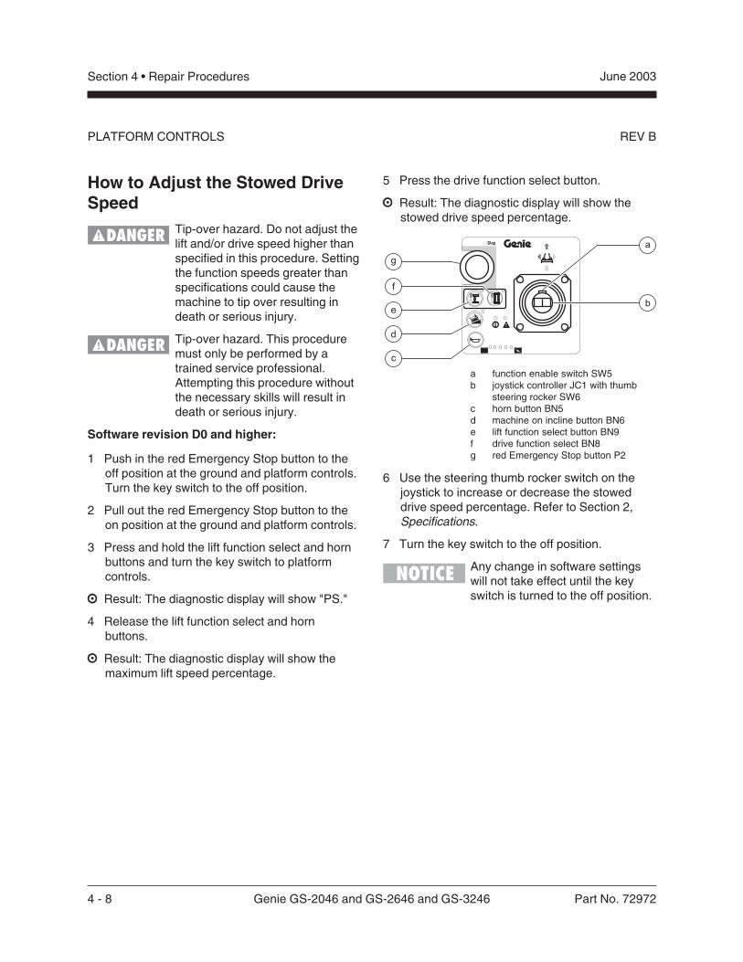
5 Press the drive function select button.
Result: The diagnostic display will show thestowed drive speed percentage.
a function enable switch SW5b joystick controller JC1 with thumb
steering rocker SW6c horn button BN5d machine on incline button BN6e lift function select button BN9f drive function select BN8g red Emergency Stop button P2
6 Use the steering thumb rocker switch on thejoystick to increase or decrease the stoweddrive speed percentage. Refer to Section 2,Specifications.
7 Turn the key switch to the off position.
Any change in software settingswill not take effect until the keyswitch is turned to the off position.
Part No. 72972 Genie GS-2046 and GS-2646 and GS-3246 4 - 9
June 2003 Section 4 • Repair Procedures
REV B PLATFORM CONTROLS
How to Adjust the High TorqueDrive Speed
Tip-over hazard. Do not adjust thelift and/or drive speed higher thanspecified in this procedure. Settingthe drive speed greater thanspecifications could cause themachine to tip over resulting indeath or serious injury.
Tip-over hazard. This proceduremust only be performed by atrained service professional.Attempting this procedure withoutthe necessary skills will result indeath or serious injury.
Software revision D0 and higher:
1 Push in the red Emergency Stop button to theoff position at the ground and platform controls.Turn the key switch to the off position.
2 Pull out the red Emergency Stop button to theon position at the ground and platform controls.
3 Press and hold the lift function select and hornbuttons and turn the key switch to platformcontrols.
Result: The diagnostic display will show "PS."
4 Release the lift function select and hornbuttons.
Result: The diagnostic display will show themaximum lift speed percentage.
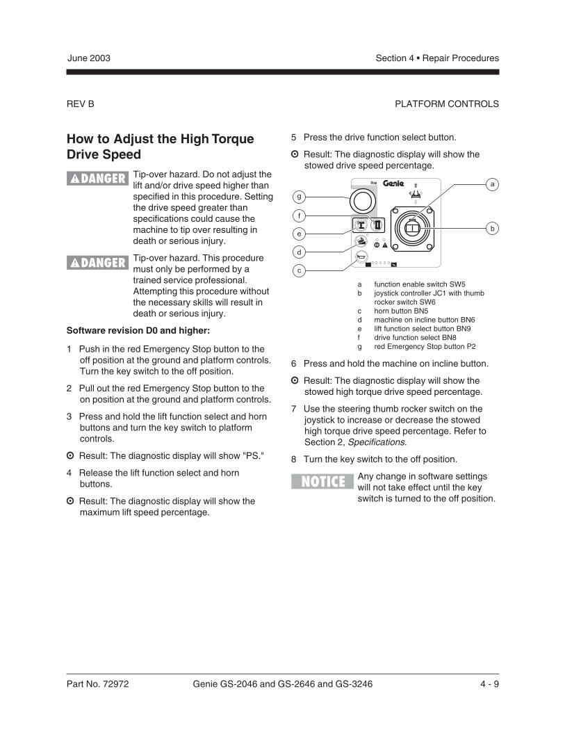
5 Press the drive function select button.
Result: The diagnostic display will show thestowed drive speed percentage.
a function enable switch SW5b joystick controller JC1 with thumb
rocker switch SW6c horn button BN5d machine on incline button BN6e lift function select button BN9f drive function select BN8g red Emergency Stop button P2
6 Press and hold the machine on incline button.
Result: The diagnostic display will show thestowed high torque drive speed percentage.
7 Use the steering thumb rocker switch on thejoystick to increase or decrease the stowedhigh torque drive speed percentage. Refer toSection 2, Specifications.
8 Turn the key switch to the off position.
Any change in software settingswill not take effect until the keyswitch is turned to the off position.
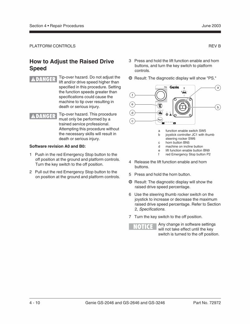
4 - 10 Genie GS-2046 and GS-2646 and GS-3246 Part No. 72972
June 2003Section 4 • Repair Procedures
REV BPLATFORM CONTROLS
How to Adjust the Raised DriveSpeed
Tip-over hazard. Do not adjust thelift and/or drive speed higher thanspecified in this procedure. Settingthe function speeds greater thanspecifications could cause themachine to tip over resulting indeath or serious injury.
Tip-over hazard. This proceduremust only be performed by atrained service professional.Attempting this procedure withoutthe necessary skills will result indeath or serious injury.
Software revision A0 and B0:
1 Push in the red Emergency Stop button to theoff position at the ground and platform controls.Turn the key switch to the off position.
2 Pull out the red Emergency Stop button to theon position at the ground and platform controls.
3 Press and hold the lift function enable and hornbuttons, and turn the key switch to platformcontrols.
Result: The diagnostic display will show "PS."
a function enable switch SW5b joystick controller JC1 with thumb
steering rocker SW6c horn button BN5d machine on incline buttone lift function enable button BN9f red Emergency Stop button P2
4 Release the lift function enable and hornbuttons.
5 Press and hold the horn button.
Result: The diagnostic display will show theraised drive speed percentage.
6 Use the steering thumb rocker switch on thejoystick to increase or decrease the maximumraised drive speed percentage. Refer to Section2, Specifications.
7 Turn the key switch to the off position.
Any change in software settingswill not take effect until the keyswitch is turned to the off position.
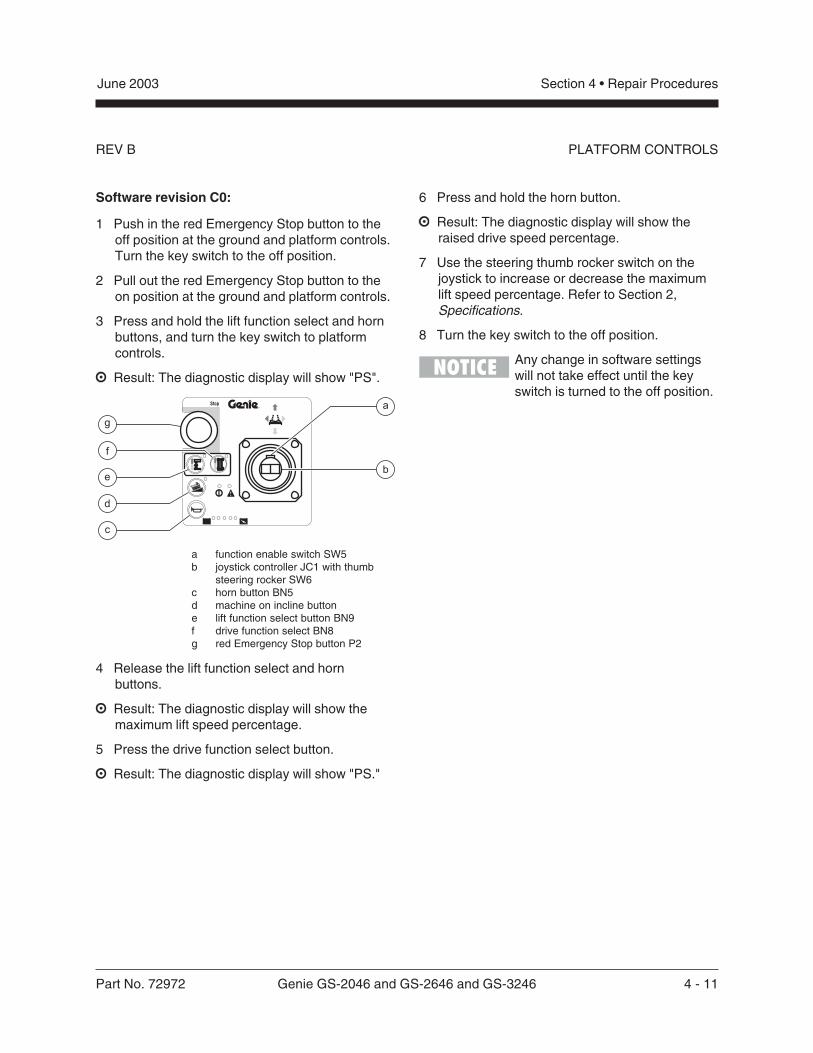
Part No. 72972 Genie GS-2046 and GS-2646 and GS-3246 4 - 11
June 2003 Section 4 • Repair Procedures
REV B
Software revision C0:
1 Push in the red Emergency Stop button to theoff position at the ground and platform controls.Turn the key switch to the off position.
2 Pull out the red Emergency Stop button to theon position at the ground and platform controls.
3 Press and hold the lift function select and hornbuttons, and turn the key switch to platformcontrols.
Result: The diagnostic display will show "PS".
a function enable switch SW5b joystick controller JC1 with thumb
steering rocker SW6c horn button BN5d machine on incline buttone lift function select button BN9f drive function select BN8g red Emergency Stop button P2
4 Release the lift function select and hornbuttons.
Result: The diagnostic display will show themaximum lift speed percentage.
5 Press the drive function select button.
Result: The diagnostic display will show "PS."
6 Press and hold the horn button.
Result: The diagnostic display will show theraised drive speed percentage.
7 Use the steering thumb rocker switch on thejoystick to increase or decrease the maximumlift speed percentage. Refer to Section 2,Specifications.
8 Turn the key switch to the off position.
Any change in software settingswill not take effect until the keyswitch is turned to the off position.
PLATFORM CONTROLS
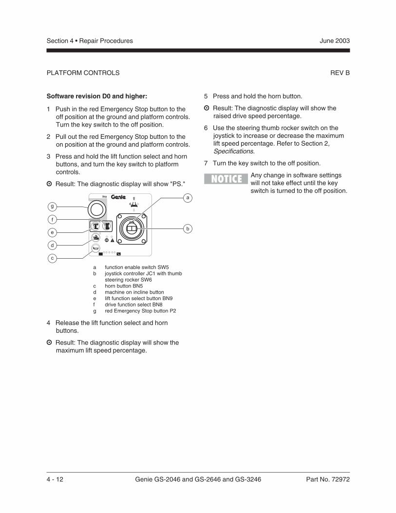
4 - 12 Genie GS-2046 and GS-2646 and GS-3246 Part No. 72972
June 2003Section 4 • Repair Procedures
REV B
Software revision D0 and higher:
1 Push in the red Emergency Stop button to theoff position at the ground and platform controls.Turn the key switch to the off position.
2 Pull out the red Emergency Stop button to theon position at the ground and platform controls.
3 Press and hold the lift function select and hornbuttons, and turn the key switch to platformcontrols.
Result: The diagnostic display will show "PS."
a function enable switch SW5b joystick controller JC1 with thumb
steering rocker SW6c horn button BN5d machine on incline buttone lift function select button BN9f drive function select BN8g red Emergency Stop button P2
4 Release the lift function select and hornbuttons.
Result: The diagnostic display will show themaximum lift speed percentage.
5 Press and hold the horn button.
Result: The diagnostic display will show theraised drive speed percentage.
6 Use the steering thumb rocker switch on thejoystick to increase or decrease the maximumlift speed percentage. Refer to Section 2,Specifications.
7 Turn the key switch to the off position.
Any change in software settingswill not take effect until the keyswitch is turned to the off position.
PLATFORM CONTROLS
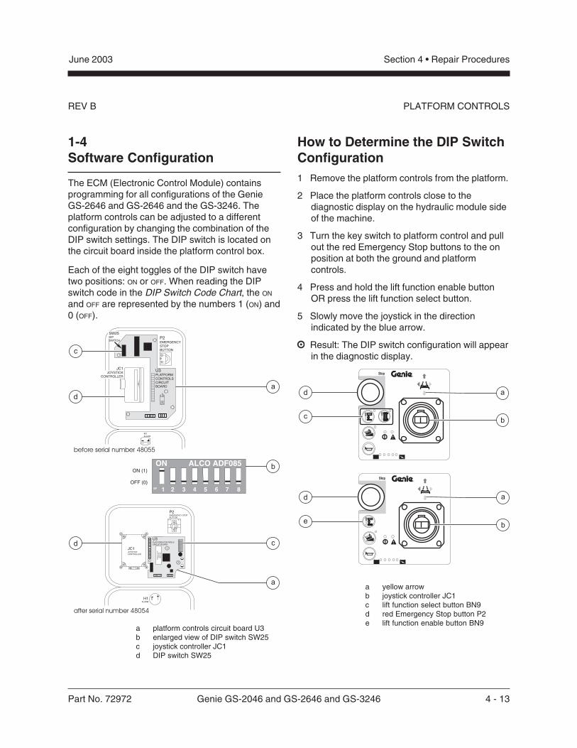
Part No. 72972 Genie GS-2046 and GS-2646 and GS-3246 4 - 13
June 2003 Section 4 • Repair Procedures
REV B
1-4Software Configuration
The ECM (Electronic Control Module) containsprogramming for all configurations of the GenieGS-2646 and GS-2646 and the GS-3246. Theplatform controls can be adjusted to a differentconfiguration by changing the combination of theDIP switch settings. The DIP switch is located onthe circuit board inside the platform control box.
Each of the eight toggles of the DIP switch havetwo positions: ON or OFF. When reading the DIPswitch code in the DIP Switch Code Chart, the ON
and OFF are represented by the numbers 1 (ON) and0 (OFF).
PLATFORM CONTROLS
a platform controls circuit board U3b enlarged view of DIP switch SW25c joystick controller JC1d DIP switch SW25
P2EMERGENCYSTOPBUTTON
H1ALARM
21
bON (1)
OFF (0)
SW25DIPSWITCH
U3PLATFORMCONTROLSCIRCUITBOARD
JC1JOYSTICK
CONTROLLER
c
d
a
19F 2 3 4 5 6 7 8
ON ALCO ADF085
P2EMERGENCY STOPBUTTON
H1ALARM
U3PLATFORM CONTROLSCIRCUIT BOARD
14.25.
2
1 NC
19
F2
34
56
78
ON
AL
CO
AD
F0
85
P/N
00
00
00
Da
te0
00
0
S/N
Al0
00
00
00
0
JC1JOYSTICKCONTROLLER
c
a
d
before serial number 48055
after serial number 48054
How to Determine the DIP SwitchConfiguration1 Remove the platform controls from the platform.
2 Place the platform controls close to thediagnostic display on the hydraulic module sideof the machine.
3 Turn the key switch to platform control and pullout the red Emergency Stop buttons to the onposition at both the ground and platformcontrols.
4 Press and hold the lift function enable buttonOR press the lift function select button.
5 Slowly move the joystick in the directionindicated by the blue arrow.
Result: The DIP switch configuration will appearin the diagnostic display.
a yellow arrowb joystick controller JC1c lift function select button BN9d red Emergency Stop button P2e lift function enable button BN9
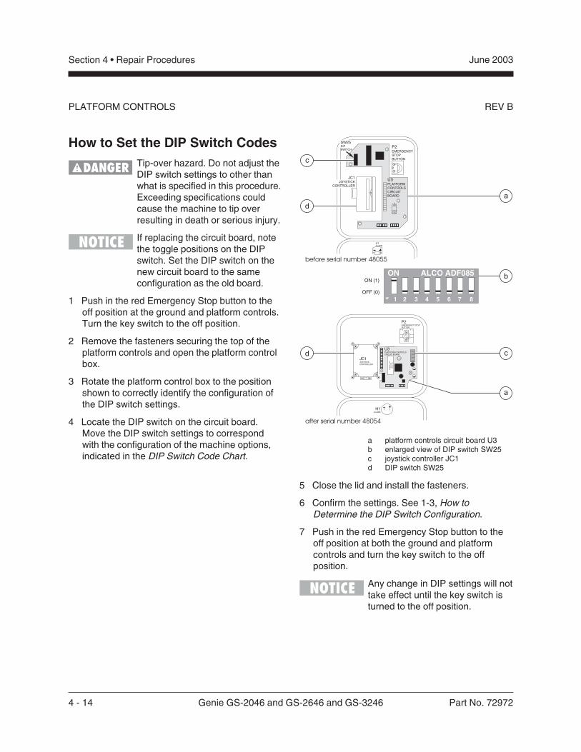
4 - 14 Genie GS-2046 and GS-2646 and GS-3246 Part No. 72972
June 2003Section 4 • Repair Procedures
REV B
How to Set the DIP Switch CodesTip-over hazard. Do not adjust theDIP switch settings to other thanwhat is specified in this procedure.Exceeding specifications couldcause the machine to tip overresulting in death or serious injury.
If replacing the circuit board, notethe toggle positions on the DIPswitch. Set the DIP switch on thenew circuit board to the sameconfiguration as the old board.
1 Push in the red Emergency Stop button to theoff position at the ground and platform controls.Turn the key switch to the off position.
2 Remove the fasteners securing the top of theplatform controls and open the platform controlbox.
3 Rotate the platform control box to the positionshown to correctly identify the configuration ofthe DIP switch settings.
4 Locate the DIP switch on the circuit board.Move the DIP switch settings to correspondwith the configuration of the machine options,indicated in the DIP Switch Code Chart.
a platform controls circuit board U3b enlarged view of DIP switch SW25c joystick controller JC1d DIP switch SW25
5 Close the lid and install the fasteners.
6 Confirm the settings. See 1-3, How toDetermine the DIP Switch Configuration.
7 Push in the red Emergency Stop button to theoff position at both the ground and platformcontrols and turn the key switch to the offposition.
Any change in DIP settings will nottake effect until the key switch isturned to the off position.
PLATFORM CONTROLS
P2EMERGENCYSTOPBUTTON
H1ALARM
21
bON (1)
OFF (0)
SW25DIPSWITCH
U3PLATFORMCONTROLSCIRCUITBOARD
JC1JOYSTICK
CONTROLLER
c
d
a
19F 2 3 4 5 6 7 8
ON ALCO ADF085
P2EMERGENCY STOPBUTTON
H1ALARM
U3PLATFORM CONTROLSCIRCUIT BOARD
14.25.
2
1 NC
19
F2
34
56
78
ON
AL
CO
AD
F0
85
P/N
00
00
00
Da
te0
00
0
S/N
Al0
00
00
00
0
JC1JOYSTICKCONTROLLER
c
a
d
before serial number 48055
after serial number 48054
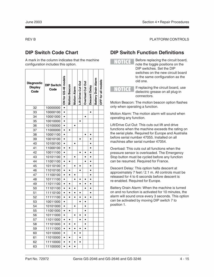
Part No. 72972 Genie GS-2046 and GS-2646 and GS-3246 4 - 15
June 2003 Section 4 • Repair Procedures
REV B PLATFORM CONTROLS
DIP Switch Code ChartA mark in the column indicates that the machineconfiguration includes this option.
DIP Switch Function DefinitionsBefore replacing the circuit board,note the toggle positions on theDIP switches. Set the DIPswitches on the new circuit boardto the same configuration as theold one.
If replacing the circuit board, usedielectric grease on all plug-inconnectors.
Motion Beacon: The motion beacon option flashesonly when operating a function.
Motion Alarm: The motion alarm will sound whenoperating any function.
Lift/Drive Cut Out: This cuts out lift and drivefunctions when the machine exceeds the rating onthe serial plate. Required for Europe and Australiabefore serial number 47055. Installed on allmachines after serial number 47054.
Overload: This cuts out all functions when thepressure sensor is overloaded. The EmergencyStop button must be cycled before any functioncan be resumed. Required for France.
Descent Delay: This option halts descent atapproximately 7 feet / 2.1 m. All controls must bereleased for 4 to 6 seconds before descent isre-enabled. Required for Europe.
Battery Drain Alarm: When the machine is turnedon and no function is activated for 10 minutes, thealarm will sound once every 3 seconds. This optioncan be activated by moving DIP switch 7 toposition 1.
Diagnostic Display Code
DIP Switch Code
ON
fo
r G
S-4
6 m
od
els
Mo
tio
n B
eaco
n
Mo
tio
n A
larm
Lif
t D
rive
Cu
t O
ut
Ove
rlo
ad C
ut
Ou
t
Des
cen
t D
elay
Bat
tery
Dra
in A
larm
OF
F f
or
all m
od
els
32 10000000 •33 10000100 • •34 10001000 • •35 10010000 • •36 10100000 • •37 11000000 • •38 10001100 • • •39 10010100 • • •40 10100100 • • •41 11000100 • • •42 10011100 • • • •43 10101100 • • • •44 11001100 • • • •45 10110100 • • • •46 11010100 • • • •47 11100100 • • • •48 10111100 • • • • •49 11011100 • • • • •50 11101100 • • • • •51 11110100 • • • • •52 11111100 • • • • • •53 10011000 • • •54 10101000 • • •55 11001000 • • •56 10111000 • • • •57 11011000 • • • •58 11101000 • • • •59 11111000 • • • • •60 10110000 • • •61 11010000 • • •62 11110000 • • • •63 11100000 • • •
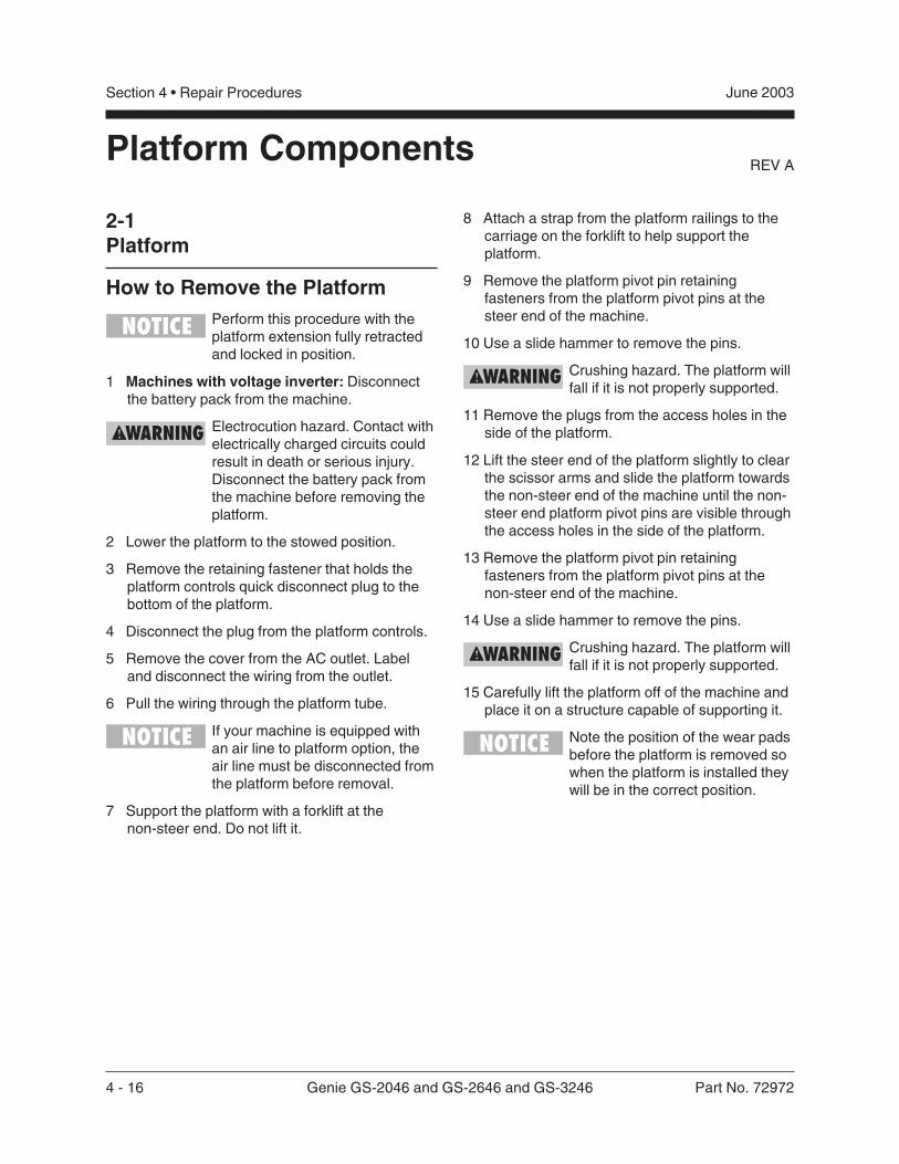
4 - 16 Genie GS-2046 and GS-2646 and GS-3246 Part No. 72972
June 2003Section 4 • Repair Procedures
REV A
2-1Platform
How to Remove the PlatformPerform this procedure with theplatform extension fully retractedand locked in position.
1 Machines with voltage inverter: Disconnectthe battery pack from the machine.
Electrocution hazard. Contact withelectrically charged circuits couldresult in death or serious injury.Disconnect the battery pack fromthe machine before removing theplatform.
2 Lower the platform to the stowed position.
3 Remove the retaining fastener that holds theplatform controls quick disconnect plug to thebottom of the platform.
4 Disconnect the plug from the platform controls.
5 Remove the cover from the AC outlet. Labeland disconnect the wiring from the outlet.
6 Pull the wiring through the platform tube.
If your machine is equipped withan air line to platform option, theair line must be disconnected fromthe platform before removal.
7 Support the platform with a forklift at thenon-steer end. Do not lift it.
Platform Components
8 Attach a strap from the platform railings to thecarriage on the forklift to help support theplatform.
9 Remove the platform pivot pin retainingfasteners from the platform pivot pins at thesteer end of the machine.
10 Use a slide hammer to remove the pins.
Crushing hazard. The platform willfall if it is not properly supported.
11 Remove the plugs from the access holes in theside of the platform.
12 Lift the steer end of the platform slightly to clearthe scissor arms and slide the platform towardsthe non-steer end of the machine until the non-steer end platform pivot pins are visible throughthe access holes in the side of the platform.
13 Remove the platform pivot pin retainingfasteners from the platform pivot pins at thenon-steer end of the machine.
14 Use a slide hammer to remove the pins.
Crushing hazard. The platform willfall if it is not properly supported.
15 Carefully lift the platform off of the machine andplace it on a structure capable of supporting it.
Note the position of the wear padsbefore the platform is removed sowhen the platform is installed theywill be in the correct position.
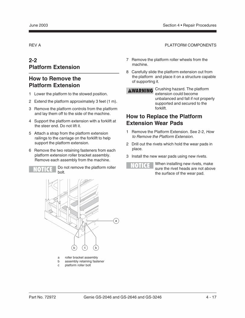
Part No. 72972 Genie GS-2046 and GS-2646 and GS-3246 4 - 17
June 2003 Section 4 • Repair Procedures
REV A PLATFORM COMPONENTS
2-2Platform Extension
How to Remove thePlatform Extension1 Lower the platform to the stowed position.
2 Extend the platform approximately 3 feet (1 m).
3 Remove the platform controls from the platformand lay them off to the side of the machine.
4 Support the platform extension with a forklift atthe steer end. Do not lift it.
5 Attach a strap from the platform extensionrailings to the carriage on the forklift to helpsupport the platform extension.
6 Remove the two retaining fasteners from eachplatform extension roller bracket assembly.Remove each assembly from the machine.
Do not remove the platform rollerbolt.
a roller bracket assemblyb assembly retaining fastenerc platform roller bolt
7 Remove the platform roller wheels from themachine.
8 Carefully slide the platform extension out fromthe platform and place it on a structure capableof supporting it.
Crushing hazard. The platformextension could becomeunbalanced and fall if not properlysupported and secured to theforklift.
How to Replace the PlatformExtension Wear Pads1 Remove the Platform Extension. See 2-2, How
to Remove the Platform Extension.
2 Drill out the rivets which hold the wear pads inplace.
3 Install the new wear pads using new rivets.
When installing new rivets, makesure the rivet heads are not abovethe surface of the wear pad.

4 - 18 Genie GS-2046 and GS-2646 and GS-3246 Part No. 72972
June 2003Section 4 • Repair Procedures
REV A
1 Number 4 pivot pin (steer end)2 Number 3 center pivot pin3 Lift cylinder rod-end pivot pin4 Number 3 pivot pin (steer end)5 Number 2 center pivot pin (2pins)6 Number 2 pivot pin (steer end)7 Number 1 center pivot pin8 Number 1 inner arm9 Number 1 pivot pin (steer end) (2pins)
10 Number 4 pivot pin (non-steer end)11 Number 3 inner arm12 Number 3 outer arm13 Number 3 pivot pin (non-steer end)14 Number 2 inner arm15 Number 2 outer arm16 Number 2 pivot pin (non-steer end)17 Lift cylinder barrel-end pivot pin18 Number 1 outer arm
Scissor Components
Non-steer EndSteer End
Part No. 72972 Genie GS-2046 and GS-2646 and GS-3246 4 - 19
June 2003 Section 4 • Repair Procedures
REV A
3-1Scissor Assembly, GS-2046
How to Disassemble theScissor Assembly, GS-2046
Bodily injury hazard. Thisprocedure requires specific repairskills, lifting equipment and asuitable workshop. Attempting thisprocedure without these skills andtools could result in death orserious injury and significantcomponent damage. Dealerservice is required.
When removing a hose assemblyor fitting, the O-ring on the fittingand/or hose end must be replacedand then torqued to specificationduring installation. Refer toSection Two, Hydraulic Hose andFitting Torque Specifications.
1 Remove the platform. See 2-1, How to Removethe Platform.
2 Remove the cables from the side of the number3 outer arm (index #12) at the ground controlsside.
Component damage hazard.Cables can be damaged if theyare kinked or pinched.
3 Attach a lifting strap from an overhead crane tothe number 3 outer arm (index #12).
4 Remove the external snap rings from thenumber 3 center pivot pin (index #2).
5 Use a soft metal drift to remove the number 3center pivot pin (index #2).
6 Remove the external snap rings from thenumber 3 pivot pin (index #13).
7 Use a soft metal drift to remove the number 3pivot pin (index #13) from the non-steer end ofthe machine. Remove the number 3 outer arm(index #12) from the machine.
Crushing hazard. The number 3outer arm (index #12) maybecome unbalanced and fall if notproperly supported when it isremoved from the machine.
8 Remove the cable clamps from the number 3inner arm (index #11).
9 Remove the mounting fasteners from the cabletray support at the steer end.
10 Remove the external snap rings from thenumber 2 center pivot pin (index #5) at theground controls side. Do not remove the pin.
11 Slide the cable tray towards the battery packside of the machine and remove it from themachine.
Component damage hazard.Cables can be damaged if theyare kinked or pinched.
SCISSOR COMPONENTS
4 - 20 Genie GS-2046 and GS-2646 and GS-3246 Part No. 72972
June 2003Section 4 • Repair Procedures
REV ASCISSOR COMPONENTS
12 Attach a lifting strap from an overhead crane tothe lug on the rod end of the lift cylinder.
13 Remove the pin retaining fasteners from thecylinder rod-end pivot pin (index #3). Use a softmetal drift to remove the pin.
Bodily injury hazard. The cylindermay fall if not properly supportedwhen the pin is removed.
14 Lower the cylinder onto the number 1 centerpivot pin (index #7).
15 Attach a lifting strap from an overhead crane tothe number 3 inner arm (index #11).
16 Remove the external snap rings from thenumber 3 pivot pin (index #4).
17 Use a soft metal drift to remove the number 3pivot pin (index #4). Remove the number 3inner arm (index #11) from the machine.
Bodily injury hazard. The number3 inner arm (index #11) maybecome unbalanced and fall if notproperly supported when it isremoved from the machine.
18 Attach a strap from an overhead crane to thenumber 2 outer arm (index #15) at the groundcontrols side.
19 Use a soft metal drift to remove the number 2center pivot pin (index #5) at the groundcontrols side.
20 Remove the external snap rings from thenumber 2 pivot pin (index #16) at the non-steerend.
21 Use a soft metal drift to remove the number 2pivot pin (index #16) at the non-steer end.Remove the number 2 outer arm (index #15)from the ground controls side of the machine.
Bodily injury hazard. The number2 outer arm (index #15) at theground controls side may becomeunbalanced and fall if not properlysupported when it is removed fromthe machine.
22 Attach a lifting strap from an overhead crane tothe number 2 outer arm (index #15) at thebattery pack side.
23 Remove the external snap rings from thenumber 2 center pivot pin (index #5) at thebattery pack side.
24 Use a soft metal drift to remove the number 2center pivot pin (index #5) at the battery packside. Remove the number 2 outer arm (index#15) from the battery pack side of the machine.
Bodily injury hazard. The number2 outer arm (index #15) at thebattery pack side may becomeunbalanced and fall if not properlysupported when it is removed fromthe machine.
25 Attach a lifting strap from an overhead crane tothe number 2 inner arm (index #14).
26 Remove the external snap rings from thenumber 2 pivot pin (index #6) from the steerend of the machine.
Part No. 72972 Genie GS-2046 and GS-2646 and GS-3246 4 - 21
June 2003 Section 4 • Repair Procedures
REV A SCISSOR COMPONENTS
27 Use a soft metal drift to remove the number 2pivot pin (index #6). Remove the number 2inner arm (index #14) from the machine.
Bodily injury hazard. The number2 inner arm (index #14) at thebattery pack side may becomeunbalanced and fall if not properlysupported when it is removed fromthe machine.
28 Remove the safety arm from the number 2 innerarm (index #14) that was just removed.
29 Attach a lifting strap from an overhead crane tothe number 1 inner arm (index #8) at the non-steering end.
30 Raise the number 1 inner arm (index #8)approximately 2 feet (60 cm) and insert thesafety arm between the number 1 inner arm(index #8) and the number 1 outer arm(index #18). Lower the scissor arms onto thesafety arm.
Bodily injury hazard. Keep handsclear of moving parts wheninserting the safety arm.
31 Disconnect and plug the hydraulic hose on thelift cylinder. Cap the fitting on the cylinder.
Bodily injury hazard. Sprayinghydraulic oil can penetrate andburn skin. Loosen hydraulicconnections very slowly to allowthe oil pressure to dissipategradually. Do not allow oil to squirtor spray.
32 Tag and disconnect the wires from the solenoidvalve on the cylinder.
33 Attach a lifting strap from an overhead crane tothe lug on the rod end of the lift cylinder. Raisethe lift cylinder to a vertical position.
34 Remove the pin retaining fasteners from the liftcylinder barrel-end pivot pin (index #17). Use asoft metal drift to remove the pin. Remove thecylinder from the machine.
Crushing hazard. The cylindermay become unbalanced and fallwhen it is removed from themachine if it is not properlyattached to the overhead crane.
Component damage hazard. Becareful not to damage the valve orfittings on the cylinder whileremoving it from the machine.
35 Place a 4 x 4 x 48 inch / 10 cm x 10 cm x1.2 m long block across both sides of thechassis under the number 1 center pivot pin(index #7).
36 Attach a lifting strap from an overhead crane tothe number 1 inner arm (index #8) at the non-steer end. Raise the number 1 inner arm(index #18) and remove the safety arm. Lowerthe number 1 inner arm (index #8) onto theblock that was placed across the chassis.
Bodily injury hazard. Keep handsclear of moving parts whenlowering the arms onto the block.
37 Remove the cables from the number 1 innerarm (index #8) and lay them off to the side.
Component damage hazard.Cables can be damaged if theyare kinked or pinched.
38 Support and secure the entry ladder to anappropriate lifting device.
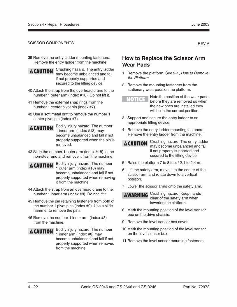
4 - 22 Genie GS-2046 and GS-2646 and GS-3246 Part No. 72972
June 2003Section 4 • Repair Procedures
REV A
39 Remove the entry ladder mounting fasteners.Remove the entry ladder from the machine.
Crushing hazard. The entry laddermay become unbalanced and fallif not properly supported andsecured to the lifting device.
40 Attach the strap from the overhead crane to thenumber 1 outer arm (index #18). Do not lift it.
41 Remove the external snap rings from thenumber 1 center pivot pin (index #7).
42 Use a soft metal drift to remove the number 1center pivot pin (index #7).
Bodily injury hazard. The number1 inner arm (index #18) maybecome unbalanced and fall if notproperly supported when the pin isremoved.
43 Slide the number 1 outer arm (index #18) to thenon-steer end and remove it from the machine.
Bodily injury hazard. The number1 outer arm (index #18) maybecome unbalanced and fall if notproperly supported when removingit from the machine.
44 Attach the strap from an overhead crane to thenumber 1 inner arm (index #8). Do not lift it.
45 Remove the pin retaining fasteners from both ofthe number 1 pivot pins (index #9). Use a slidehammer to remove the pins.
46 Remove the number 1 inner arm (index #8)from the machine.
Bodily injury hazard. The number1 inner arm (index #8) maybecome unbalanced and fall if notproperly supported when removedfrom the machine.
SCISSOR COMPONENTS
How to Replace the Scissor ArmWear Pads1 Remove the platform. See 2-1, How to Remove
the Platform.
2 Remove the mounting fasteners from thestationary wear pads on the platform.
Note the position of the wear padsbefore they are removed so whenthe new ones are installed theywill be in the correct position.
3 Support and secure the entry ladder to anappropriate lifting device.
4 Remove the entry ladder mounting fasteners.Remove the entry ladder from the machine.
Crushing hazard. The entry laddermay become unbalanced and fallif not properly supported andsecured to the lifting device.
5 Raise the platform 7 to 8 feet / 2.1 to 2.4 m.
6 Lift the safety arm, move it to the center of thescissor arm and rotate down to a verticalposition.
7 Lower the scissor arms onto the safety arm.
Crushing hazard. Keep handsclear of the safety arm whenlowering the platform.
8 Mark the mounting position of the level sensorbox on the drive chassis.
9 Remove the level sensor box cover.
10 Mark the mounting position of the level sensoron the level sensor box.
11 Remove the level sensor mounting fasteners.
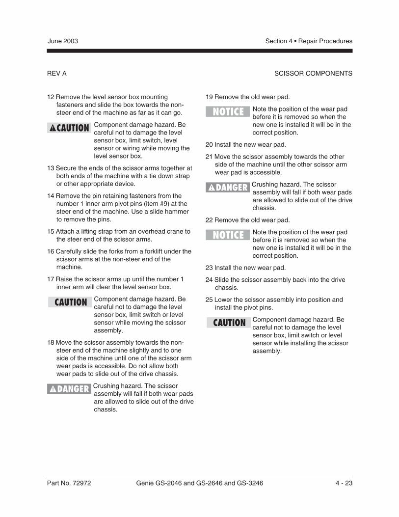
Part No. 72972 Genie GS-2046 and GS-2646 and GS-3246 4 - 23
June 2003 Section 4 • Repair Procedures
REV A
12 Remove the level sensor box mountingfasteners and slide the box towards the non-steer end of the machine as far as it can go.
Component damage hazard. Becareful not to damage the levelsensor box, limit switch, levelsensor or wiring while moving thelevel sensor box.
13 Secure the ends of the scissor arms together atboth ends of the machine with a tie down strapor other appropriate device.
14 Remove the pin retaining fasteners from thenumber 1 inner arm pivot pins (item #9) at thesteer end of the machine. Use a slide hammerto remove the pins.
15 Attach a lifting strap from an overhead crane tothe steer end of the scissor arms.
16 Carefully slide the forks from a forklift under thescissor arms at the non-steer end of themachine.
17 Raise the scissor arms up until the number 1inner arm will clear the level sensor box.
Component damage hazard. Becareful not to damage the levelsensor box, limit switch or levelsensor while moving the scissorassembly.
18 Move the scissor assembly towards the non-steer end of the machine slightly and to oneside of the machine until one of the scissor armwear pads is accessible. Do not allow bothwear pads to slide out of the drive chassis.
Crushing hazard. The scissorassembly will fall if both wear padsare allowed to slide out of the drivechassis.
19 Remove the old wear pad.
Note the position of the wear padbefore it is removed so when thenew one is installed it will be in thecorrect position.
20 Install the new wear pad.
21 Move the scissor assembly towards the otherside of the machine until the other scissor armwear pad is accessible.
Crushing hazard. The scissorassembly will fall if both wear padsare allowed to slide out of the drivechassis.
22 Remove the old wear pad.
Note the position of the wear padbefore it is removed so when thenew one is installed it will be in thecorrect position.
23 Install the new wear pad.
24 Slide the scissor assembly back into the drivechassis.
25 Lower the scissor assembly into position andinstall the pivot pins.
Component damage hazard. Becareful not to damage the levelsensor box, limit switch or levelsensor while installing the scissorassembly.
SCISSOR COMPONENTS
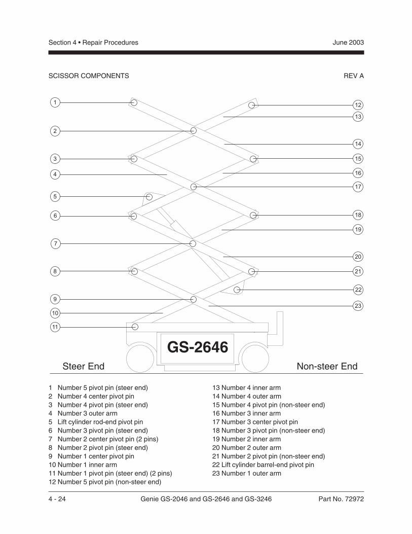
4 - 24 Genie GS-2046 and GS-2646 and GS-3246 Part No. 72972
June 2003Section 4 • Repair Procedures
REV A
1 Number 5 pivot pin (steer end)2 Number 4 center pivot pin3 Number 4 pivot pin (steer end)4 Number 3 outer arm5 Lift cylinder rod-end pivot pin6 Number 3 pivot pin (steer end)7 Number 2 center pivot pin (2 pins)8 Number 2 pivot pin (steer end)9 Number 1 center pivot pin10 Number 1 inner arm11 Number 1 pivot pin (steer end) (2 pins)12 Number 5 pivot pin (non-steer end)
13 Number 4 inner arm14 Number 4 outer arm15 Number 4 pivot pin (non-steer end)16 Number 3 inner arm17 Number 3 center pivot pin18 Number 3 pivot pin (non-steer end)19 Number 2 inner arm20 Number 2 outer arm21 Number 2 pivot pin (non-steer end)22 Lift cylinder barrel-end pivot pin23 Number 1 outer arm
Non-steer EndSteer End
SCISSOR COMPONENTS
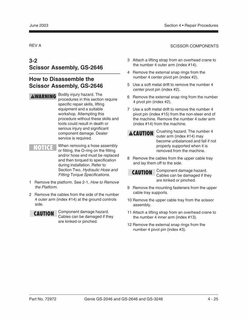
Part No. 72972 Genie GS-2046 and GS-2646 and GS-3246 4 - 25
June 2003 Section 4 • Repair Procedures
REV A
3-2Scissor Assembly, GS-2646
How to Disassemble theScissor Assembly, GS-2646
Bodily injury hazard. Theprocedures in this section requirespecific repair skills, liftingequipment and a suitableworkshop. Attempting thisprocedure without these skills andtools could result in death orserious injury and significantcomponent damage. Dealerservice is required.
When removing a hose assemblyor fitting, the O-ring on the fittingand/or hose end must be replacedand then torqued to specificationduring installation. Refer toSection Two, Hydraulic Hose andFitting Torque Specifications.
1 Remove the platform. See 2-1, How to Removethe Platform.
2 Remove the cables from the side of the number4 outer arm (index #14) at the ground controlsside.
Component damage hazard.Cables can be damaged if theyare kinked or pinched.
3 Attach a lifting strap from an overhead crane tothe number 4 outer arm (index #14).
4 Remove the external snap rings from thenumber 4 center pivot pin (index #2).
5 Use a soft metal drift to remove the number 4center pivot pin (index #2).
6 Remove the external snap ring from the number4 pivot pin (index #2).
7 Use a soft metal drift to remove the number 4pivot pin (index #15) from the non-steer end ofthe machine. Remove the number 4 outer arm(index #14) from the machine.
Crushing hazard. The number 4outer arm (index #14) maybecome unbalanced and fall if notproperly supported when it isremoved from the machine.
8 Remove the cables from the upper cable trayand lay them off to the side.
Component damage hazard.Cables can be damaged if theyare kinked or pinched.
9 Remove the mounting fasteners from the uppercable tray supports.
10 Remove the upper cable tray from the scissorassembly.
11 Attach a lifting strap from an overhead crane tothe number 4 inner arm (index #13).
12 Remove the external snap rings from thenumber 4 pivot pin (index #3).
SCISSOR COMPONENTS
4 - 26 Genie GS-2046 and GS-2646 and GS-3246 Part No. 72972
June 2003Section 4 • Repair Procedures
REV ASCISSOR COMPONENTS
13 Use a soft metal drift to remove the number 4pivot pin (index #3) at the steer end. Removethe number 4 inner arm (index #13) from themachine.
Crushing hazard. The number 4inner arm (index #13) maybecome unbalanced and fall if notproperly supported when it isremoved.
14 Attach a lifting strap from an overhead crane tothe number 3 outer arm (index #4) at theground controls side.
15 Remove the external snap rings from thenumber 3 center pivot pin (index #17).
16 Use a soft metal drift to remove the number 3center pivot pin (index #17).
17 Remove the external snap rings from thenumber 3 pivot pin (index #18) at the non-steerend of the machine. Do not remove the pin.
18 Use a soft metal drift to tap the number 3 pivotpin (index #18) halfway out at the non-steer endof the machine. Remove the number 3 outerarm (index #4) at the ground controls side fromthe machine.
Bodily injury hazard. The number3 outer arm (index #4) at theground controls side may becomeunbalanced and fall if not properlysupported when it is removed fromthe machine.
19 Attach a lifting strap from an overhead crane tothe number 3 outer arm (index #4) at thebattery pack side.
20 Use a soft metal drift to tap the number 3 pivotpin (index #18) in the other direction. Removethe number 3 outer arm (index #4) from thebattery pack side of the machine.
Bodily injury hazard. The number3 outer arm (index #4) at thebattery pack side may becomeunbalanced and fall if not properlysupported when it is removed fromthe machine.
21 Remove the number 3 pivot pin (index #18)from the non-steer end of the machine.
22 Attach a lifting strap from an overhead crane tothe lug on the rod end of the lift cylinder forsupport. Do not lift it.
23 Remove the pin retaining fasteners from the liftcylinder rod-end pivot pin (index #5). Use a softmetal drift to remove the pin.
Bodily injury hazard. The cylindermay fall when the rod-end pivotpin is removed if it is not properlysupported.
24 Lower the cylinder onto the number 1 centerpivot pin (index #9).
25 Remove the cables from the number 3 innerarm (index #16) and lay them to the side.
26 Attach a lifting strap from an overhead crane tothe number 3 inner arm (index #16).
27 Remove the external snap rings from thenumber 3 pivot pin (index #6) at the steer end.
Part No. 72972 Genie GS-2046 and GS-2646 and GS-3246 4 - 27
June 2003 Section 4 • Repair Procedures
REV A
28 Use a soft metal drift to remove the number 3pivot pin (index #6). Remove the number 3inner arm (index #16) from the machine.
Bodily injury hazard. The number3 inner arm (index #16) maybecome unbalanced and fall if notproperly supported when it isremoved from the machine.
29 Remove the cable clamps from the lower cabletray. Lay the cables to the side.
Component damage hazard.Cables can be damaged if theyare kinked or pinched.
30 Remove the mounting fasteners from the lowercable tray supports.
31 Remove the mounting fasteners from the lowercable tray mounting bracket on the number 2center pivot pin (index #7) at the groundcontrols side of the machine.
32 Slide the cable tray towards the battery packside of the machine and remove it from themachine.
33 Attach a lifting strap from an overhead crane tothe number 2 outer arm (index #20) at theground controls side.
34 Remove the external snap rings from thenumber 2 center pivot pin (index #7) at theground controls side.
35 Use a soft metal drift to remove the number 2center pivot pin (index #7) at the groundcontrols side.
36 Use a soft metal drift to tap the number 2 pivotpin (index #21) halfway out at the non-steer endof the machine. Remove the number 2 outerarm (index #20) from the ground controls sideof the machine.
Bodily injury hazard. The number2 outer arm (index #20) at theground controls side may becomeunbalanced and fall if not properlysupported when it is removed fromthe machine.
37 Attach a lifting strap from an overhead crane tothe number 2 outer arm (index #20) at thebattery pack side.
38 Remove the external snap rings from thenumber 2 center pivot pin (index #7) at thebattery pack side.
39 Use a soft metal drift to remove the number 2center pivot pin (index #7) at the battery packside.
Bodily injury hazard. The number2 outer arm (index #20) at thebattery pack side may becomeunbalanced and fall if not properlysupported when it is removed fromthe machine.
SCISSOR COMPONENTS
4 - 28 Genie GS-2046 and GS-2646 and GS-3246 Part No. 72972
June 2003Section 4 • Repair Procedures
REV A
40 Use a soft metal drift to tap the number 2 pivotpin (index #21) in the other direction. Removethe number 2 outer arm (index #20) from thebattery pack side of the machine.
Bodily injury hazard. The number2 outer arm (index #20) at thebattery pack side may becomeunbalanced and fall if not properlysupported when it is removed fromthe machine.
41 Attach a lifting strap from an overhead crane tothe number 2 inner arm (index #19).
42 Remove the external snap rings from thenumber 2 pivot pin (index #8) at the steer endof the machine.
43 Use a soft metal drift to remove the number 2pivot pin (index #8). Remove the number 2inner arm (index #19) from the machine.
Bodily injury hazard. The number2 inner arm (index #19) maybecome unbalanced and fall if notproperly supported when it isremoved from the machine.
44 Remove the safety arm from the number 2 innerarm (index #19) that was just removed.
45 Attach a lifting strap from an overhead crane tothe number 1 inner arm (index #10).
46 Raise the number 1 inner arm (index #10)approximately 2 feet (60 cm) and install thesafety arm between the number 1 inner arm(index #10) and the number 1 outer arm(index #23). Lower the scissor arms onto thesafety arm.
Bodily injury hazard. Keep handsclear of moving parts wheninserting the safety arm.
47 Disconnect and plug the hydraulic hose on thelift cylinder. Cap the fitting on the cylinder.
Bodily injury hazard. Sprayinghydraulic oil can penetrate andburn skin. Loosen hydraulicconnections very slowly to allowthe oil pressure to dissipategradually. Do not allow oil to squirtor spray.
48 Tag and disconnect the wires from the solenoidvalve on the cylinder.
49 Attach a lifting strap from an overhead crane tothe lug on the rod end of the lift cylinder. Raisethe lift cylinder to a vertical position.
SCISSOR COMPONENTS
Part No. 72972 Genie GS-2046 and GS-2646 and GS-3246 4 - 29
June 2003 Section 4 • Repair Procedures
REV A
50 Remove the pin retaining fasteners from the liftcylinder barrel-end pin (index #22). Use a softmetal drift to remove the pin. Remove thecylinder from the machine.
Crushing hazard. The cylindermay become unbalanced and fallwhen it is removed from themachine if it is not properlyattached to the overhead crane.
Component damage hazard. Becareful not to damage the valve orfittings on the cylinder whileremoving it from the machine.
51 Place a 4 x 4 x 48 inch / 10 cm x 10 cm x1.2 m long block across both sides of thechassis under the number 1 center pivot pin(index #9).
52 Attach a lifting strap from an overhead crane tothe number 1 inner arm (index #10) at the non-steer end. Raise the number 1 inner arm andremove the safety arm. Lower the number 1inner arm (index #10) onto the block that wasplaced across the chassis.
Bodily injury hazard. Keep handsclear of moving parts whenlowering the arms onto the block.
53 Remove the cables and hydraulic hoses fromthe number 1 inner arm (index #10) and laythem to the side.
Component damage hazard.Cables and hoses can bedamaged if they are kinked orpinched.
54 Support and secure the entry ladder to anappropriate lifting device.
55 Remove the entry ladder mounting fasteners.Remove the entry ladder from the machine.
Crushing hazard. The entry laddermay become unbalanced and fallif not properly supported andsecured to the lifting device.
56 Attach a lifting strap from an overhead crane tothe number 1 outer arm (index #23). Do notlift it.
57 Remove the external snap rings from thenumber 1 center pivot pin (index #9).
58 Use a soft metal drift to remove the number 1center pivot pin (index #9).
Bodily injury hazard. The number1 outer arm (index #23) maybecome unbalanced and fall if notproperly supported when the pin isremoved.
59 Slide the number 1 outer arm (index #23) to thenon-steer end and remove it from the machine.
Bodily injury hazard. The number1 outer arm (index #23) maybecome unbalanced and fall if notproperly supported when it isremoved from the machine.
Note the position of the wear padsbefore the arm is removed sowhen the scissor is assembledthey will be in the correct position.
SCISSOR COMPONENTS
4 - 30 Genie GS-2046 and GS-2646 and GS-3246 Part No. 72972
June 2003Section 4 • Repair Procedures
REV A
60 Attach the strap from an overhead crane to thenumber 1 inner arm (index #10). Do not lift it.
61 Remove the pin retaining fasteners from both ofthe number 1 pivot pins (index #11) at the steerend of the machine. Use a slide hammer toremove the pins.
62 Remove the number 1 inner arm (index #10)from the machine.
Bodily injury hazard. The number1 inner arm (index #10) maybecome unbalanced and fall if notproperly supported when it isremoved from the machine.
Component damage hazard. Besure not to damage the limit switchor level sensor box componentswhen the number 1 inner arm(index #10) is removed from themachine.
How to Replace the Scissor ArmWear Pads1 Remove the platform. See 2-1, How to Remove
the Platform.
2 Remove the mounting fasteners from thestationary wear pads on the platform.
Note the position of the wear padsbefore they are removed so whenthe new ones are installed theywill be in the correct position.
3 Support and secure the entry ladder to anappropriate lifting device.
4 Remove the entry ladder mounting fasteners.Remove the entry ladder from the machine.
Crushing hazard. The entry laddermay become unbalanced and fallif not properly supported andsecured to the lifting device.
5 Raise the platform 7 to 8 feet / 2.1 to 2.4 m.
6 Lift the safety arm, move it to the center of thescissor arm and rotate down to a verticalposition.
7 Lower the scissor arms onto the safety arm.
Crushing hazard. Keep handsclear of the safety arm whenlowering the platform.
8 Mark the mounting position of the level sensorbox on the drive chassis.
SCISSOR COMPONENTS
Part No. 72972 Genie GS-2046 and GS-2646 and GS-3246 4 - 31
June 2003 Section 4 • Repair Procedures
REV A
9 Remove the level sensor box cover.
10 Mark the mounting position of the level sensoron the level sensor box.
11 Remove the level sensor mounting fasteners.
12 Remove the level sensor box mountingfasteners and slide the box towards the non-steer end of the machine as far as it can go.
Component damage hazard. Becareful not to damage the levelsensor box, limit switch, levelsensor or wiring while moving thelevel sensor box.
13 Secure the ends of the scissor arms together atboth ends of the machine with a tie down strapor other appropriate device.
14 Remove the pin retaining fasteners from thenumber 1 inner arm pivot pins (item #11) at thesteer end of the machine. Use a slide hammerto remove the pins.
15 Attach a lifting strap from an overhead crane tothe steer end of the scissor arms.
16 Carefully slide the forks from a forklift under thescissor arms at the non-steer end of themachine.
17 Raise the scissor arms up until the number 1inner arm will clear the level sensor box.
Component damage hazard. Becareful not to damage the levelsensor box, limit switch or levelsensor while moving the scissorassembly.
SCISSOR COMPONENTS
18 Move the scissor assembly towards the non-steer end of the machine slightly and to oneside of the machine until one of the scissor armwear pads is accessible. Do not allow bothwear pads to slide out of the drive chassis.
Crushing hazard. The scissorassembly will fall if both wear padsare allowed to slide out of the drivechassis.
19 Install the new wear pad.
Note the position of the wear padbefore it is removed so when thenew one is installed it will be in thecorrect position.
20 Move the scissor assembly towards the otherside of the machine until the other scissor armwear pad is accessible.
Crushing hazard. The scissorassembly will fall if both wear padsare allowed to slide out of the drivechassis.
21 Install the new wear pad.
Note the position of the wear padbefore it is removed so when thenew one is installed it will be in thecorrect position.
22 Slide the scissor assembly back into the drivechassis.
23 Lower the scissor assembly into position andinstall the pivot pins.
Component damage hazard. Becareful not to damage the levelsensor box, limit switch or levelsensor while installing the scissorassembly.
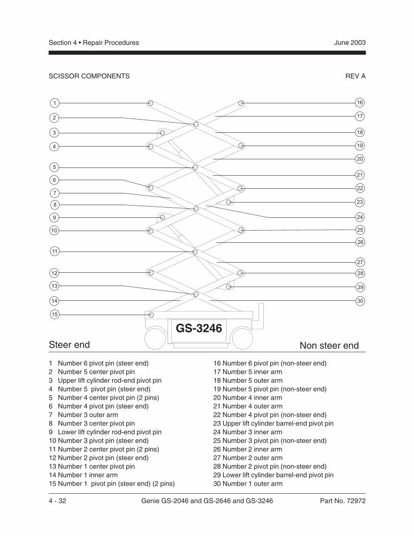
4 - 32 Genie GS-2046 and GS-2646 and GS-3246 Part No. 72972
June 2003Section 4 • Repair Procedures
REV A
1 Number 6 pivot pin (steer end)2 Number 5 center pivot pin3 Upper lift cylinder rod-end pivot pin4 Number 5 pivot pin (steer end)5 Number 4 center pivot pin (2 pins)6 Number 4 pivot pin (steer end)7 Number 3 outer arm8 Number 3 center pivot pin9 Lower lift cylinder rod-end pivot pin10 Number 3 pivot pin (steer end)11 Number 2 center pivot pin (2 pins)12 Number 2 pivot pin (steer end)13 Number 1 center pivot pin14 Number 1 inner arm15 Number 1 pivot pin (steer end) (2 pins)
16 Number 6 pivot pin (non-steer end)17 Number 5 inner arm18 Number 5 outer arm19 Number 5 pivot pin (non-steer end)20 Number 4 inner arm21 Number 4 outer arm22 Number 4 pivot pin (non-steer end)23 Upper lift cylinder barrel-end pivot pin24 Number 3 inner arm25 Number 3 pivot pin (non-steer end)26 Number 2 inner arm27 Number 2 outer arm28 Number 2 pivot pin (non-steer end)29 Lower lift cylinder barrel-end pivot pin30 Number 1 outer arm
Non steer endSteer end
SCISSOR COMPONENTS
Part No. 72972 Genie GS-2046 and GS-2646 and GS-3246 4 - 33
June 2003 Section 4 • Repair Procedures
REV A
3-3Scissor Assembly, GS-3246
How to Disassemble theScissor Assembly, GS-3246
Bodily injury hazard. Thisprocedure requires specific repairskills, lifting equipment and asuitable workshop. Attempting thisprocedure without these skills andtools could result in death orserious injury and significantcomponent damage. Dealerservice is required.
When removing a hose assemblyor fitting, the O-ring on the fittingand/or hose end must be replacedand then torqued to specificationduring installation. Refer toSection Two, Hydraulic Hose andFitting Torque Specifications.
1 Remove the platform. See 2-1, How to Removethe Platform.
2 Remove the cables from the side of the number5 outer arm (index #18) at the ground controlsside.
Component damage hazard.Cables can be damaged if theyare kinked or pinched.
3 Attach a lifting strap from an overhead crane tothe number 5 outer arm (index #18).
4 Remove the external snap rings from thenumber 5 center pivot pin (index #2).
5 Use a soft metal drift to remove the number 5center pivot pin (index #2).
6 Remove the external snap rings from thenumber 5 pivot pin (index #19).
7 Use a soft metal drift to remove the number 5pivot pin (index #19) from the non-steer end ofthe machine. Remove the number 5 outer arm(index #18) from the machine.
Crushing hazard. The number 5outer arm (index #18) maybecome unbalanced and fall if notproperly supported when it isremoved from the machine.
8 Remove the cable clamps from the number 5inner arm (index #17). Lay the cables off to theside of the machine.
9 Remove the mounting fasteners from the uppercable tray supports.
10 Remove the mounting fasteners from the uppercable tray mounting bracket on the number 4center pivot pin (index #5) at the groundcontrols side of the machine.
11 Remove the upper cable tray from the scissorassembly.
Component damage hazard.Cables can be damaged if theyare kinked or pinched.
SCISSOR COMPONENTS
4 - 34 Genie GS-2046 and GS-2646 and GS-3246 Part No. 72972
June 2003Section 4 • Repair Procedures
REV A
12 Attach a lifting strap from an overhead crane tothe lug on the rod end of the upper lift cylinder.
13 Remove the pin retaining fasteners from theupper cylinder rod-end pivot pin (index #3). Usea soft metal drift to remove the pin.
Crushing hazard. The cylindermay fall if not properly supportedwhen the pin is removed.
14 Lower the cylinder onto the number 3 centerpivot pin (index #8).
15 Attach a lifting strap from an overhead crane tothe number 5 inner arm (index #17).
16 Remove the external snap rings from thenumber 5 pivot pin (index #4).
17 Use a soft metal drift to remove the number 5pivot pin (index #4). Remove the number 5inner arm (index #17) from the machine.
Bodily injury hazard. The number5 inner arm (index #17) maybecome unbalanced and fall if notproperly supported when it isremoved from the machine.
18 Remove the external snap rings from thenumber 4 center pivot pin (index #5) at theground controls side.
19 Remove the external snap rings from thenumber 4 center pivot pin (index #5) at thebattery pack side.
20 Use a soft metal drift to remove both of thenumber 4 center pivot pins (index #5).
21 Remove the external snap rings from thenumber 4 pivot pin (index #22) at the non-steerend of the machine.
22 Use a soft metal drift to remove the number 4pivot pin (index #22). Remove the number 4outer arm (index #21) from the machine.
Bodily injury hazard. The number4 outer arm (index #21) maybecome unbalanced and fall if notproperly supported when it isremoved from the machine.
23 Attach a lifting strap from an overhead crane tothe number 4 inner arm (index #20).
24 Remove the external snap rings from thenumber 4 pivot pin (index #6) from the steerend of the machine.
25 Use a soft metal drift to remove the number 4pivot pin (index #6). Remove the number 4inner arm (index #20) from the machine.
Bodily injury hazard. The number4 inner arm (index #20) maybecome unbalanced and fall if notproperly supported when it isremoved from the machine.
26 Remove the safety arm from the number 4 innerarm (index #20) that was just removed.
SCISSOR COMPONENTS
Part No. 72972 Genie GS-2046 and GS-2646 and GS-3246 4 - 35
June 2003 Section 4 • Repair Procedures
REV A
27 Disconnect and plug the hydraulic hose on theupper lift cylinder. Cap the fitting on thecylinder.
Bodily injury hazard. Sprayinghydraulic oil can penetrate andburn skin. Loosen hydraulicconnections very slowly to allowthe oil pressure to dissipategradually. Do not allow oil to squirtor spray.
28 Tag and disconnect the wires from the solenoidvalve on the cylinder.
29 Connect the platform controls to the controlcable that was removed from the platform.
30 Connect the battery pack. Turn the key switchto ground control and pull out the EmergencyStop button to the ON position at both theplatform and ground controls.
31 Activate the up function and raise the number 2inner arm (index #26) approximately 2 feet(60 cm). Then install the safety arm betweenthe number 2 inner arm (index #26) and thenumber 1 inner arm (index #14).
Bodily injury hazard. Keep handsclear of moving parts wheninserting the safety arm.
32 Activate the down function to lower the scissorassembly onto the safety arm. Push in theEmergency Stop buttons and turn the key to theOFF position.
Bodily injury hazard. The scissorassembly may becomeunbalanced and fall if not properlysupported by the safety arm.
Bodily injury hazard. Keep handsclear of moving parts wheninserting the safety arm.
33 Attach a lifting strap from an overhead crane tothe lug on the rod end of the upper lift cylinder.Raise the rod end of the cylinder to a verticalposition.
34 Remove the pin retaining fasteners from theupper lift cylinder barrel-end pivot pin(index #23). Use a soft metal drift to remove thepin. Remove the cylinder from the machine.
Crushing hazard. If the overheadcrane is not properly attached, thecylinder may become unbalancedand fall when it is removed fromthe machine.
Component damage hazard. Becareful not to damage the valve orfittings on the cylinder whileremoving it from the machine.
35 Turn the key switch to ground control and pullout the Emergency Stop button to the ON
position at both the platform and groundcontrols.
SCISSOR COMPONENTS
4 - 36 Genie GS-2046 and GS-2646 and GS-3246 Part No. 72972
June 2003Section 4 • Repair Procedures
REV A
36 Activate the up function and raise the number 2inner arm (index #26) approximately 2 feet(60 cm). Remove the safety arm from themachine.
Bodily injury hazard. Keep handsclear of moving parts whenremoving the safety arm.
37 Activate the down function and fully lower thescissor assembly. Push in the Emergency Stopbutton and turn the key to the OFF position.Disconnect the battery pack.
Bodily injury hazard. Keep handsclear of moving parts whenlowering the scissor assembly.
38 Attach a lifting strap from an overhead crane tothe number 3 outer arm (index #7) at theground controls side.
39 Remove the external snap rings from thenumber 3 center pivot pin (index #8).
40 Use a soft metal drift to remove the number 3center pivot pin (index #8).
41 Remove the external snap rings from thenumber 3 pivot pin (index #25) at the non-steerend of the machine. Do not remove the pin.
42 Use a soft metal drift to tap the number 3 pivotpin (index #25) halfway out at the non-steer endof the machine. Remove the number 3 outerarm (index #7) at the ground controls side fromthe machine.
Bodily injury hazard. The number3 outer arm (index #7) at theground controls side may becomeunbalanced and fall if not properlysupported when removed from themachine.
43 Attach a lifting strap from an overhead crane tothe number 3 outer arm (index #7) at thebattery pack side.
44 Use a soft metal drift to tap the number 3 pivotpin (index #10) at the steer end in the otherdirection. Remove the number 3 outer arm(index #7) from the battery pack side of themachine.
Bodily injury hazard. The number3 outer arm (index #7) at thebattery pack side may becomeunbalanced and fall if not properlysupported when it is removed fromthe machine.
45 Remove the cables from the number 3 innerarm (index #24) and lay them off to the side.
Component damage hazard.Cables can be damaged if theyare kinked or pinched.
46 Remove the cables from the lower cable tray onthe number 2 inner arm (index #26). Lay thecables off to the side.
SCISSOR COMPONENTS
Part No. 72972 Genie GS-2046 and GS-2646 and GS-3246 4 - 37
June 2003 Section 4 • Repair Procedures
REV A
47 Remove the mounting fasteners from the lowercable tray supports.
48 Remove the external snap rings from thenumber 2 center pivot pin (index #11) at theground controls side. Do not remove the pin.
49 Slide the cable tray towards the battery packside of the machine and remove it from themachine.
Component damage hazard.Cables can be damaged if theyare kinked or pinched.
50 Attach a lifting strap from an overhead crane tothe lug on the rod end of the lower lift cylinder.
51 Remove the pin retaining fasteners from thelower lift cylinder rod-end pivot pin (index #9).Use a soft metal drift to remove the pin.
52 Lower the cylinder onto the number 1 centerpivot pin (index #13).
Crushing hazard. The cylindermay become unbalanced and fallwhen it is lowered if it is notproperly attached to the overheadcrane.
53 Attach a lifting strap from an overhead crane tothe number 3 inner arm (index #24).
54 Remove the external snap rings from thenumber 3 pivot pin (index #10).
55 Use a soft metal drift to remove the number 3pivot pin (index #10). Remove the number 3inner arm (index #24) from the machine.
Bodily injury hazard. The number3 inner arm (index #24) maybecome unbalanced and fall if notproperly supported when it isremoved from the machine.
56 Attach a lifting strap from an overhead crane tothe number 2 outer arm (index #27) at theground controls side.
57 Use a soft metal drift to remove the number 2center pivot pin (index #11) at the groundcontrols side.
58 Remove the external snap rings from thenumber 2 pivot pin (index #28) at the non-steerend of the machine. Do not remove the pin.
59 Use a soft metal drift to tap the number 2 pivotpin (index #28) halfway out at the non-steer endof the machine. Remove the number 2 outerarm (index #27) from the ground controls sideof the machine.
Bodily injury hazard. The number2 outer arm (index #27) at theground controls side may becomeunbalanced and fall if not properlysupported when it is removed fromthe machine.
60 Attach a lifting strap from an overhead crane tothe number 2 outer arm (index #27) at thebattery pack side.
SCISSOR COMPONENTS
4 - 38 Genie GS-2046 and GS-2646 and GS-3246 Part No. 72972
June 2003Section 4 • Repair Procedures
REV A
61 Remove the external snap rings from thenumber 2 center pivot pin (index #11) at thebattery pack side of the machine.
62 Use a soft metal drift to remove the number 2center pivot pin (index #11) at the battery packside of the machine.
63 Use a soft metal drift to tap the number 2 pivotpin (index #28) in the other direction. Removethe number 2 outer arm (index #27) from thebattery pack side of the machine.
Bodily injury hazard. The number2 outer arm (index #27) at theground controls side may becomeunbalanced and fall if not properlysupported when it is removed fromthe machine.
64 Use a soft metal drift to remove the number 2pivot pin (index #28) from the machine.
65 Attach a lifting strap from an overhead crane tothe number 2 inner arm (index #26).
66 Remove the external snap rings from thenumber 2 pivot pin (index #12) from the steerend of the machine.
67 Use a soft metal drift to remove the number 2pivot pin (index #12). Remove the number 2inner arm (index #26) from the machine.
Bodily injury hazard. The number2 inner arm (index #26) maybecome unbalanced and fall if notproperly supported when it isremoved from the machine.
68 Attach the strap from the overhead crane to thenumber 1 inner arm (index #14).
69 Using the overhead crane, lift the number 1inner arm (index #14) approximately 2 feet / 60cm. Place a 4 x 4 x 48 inch / 10 cm x 10 cm x1.2 m long block across both sides of thechassis under the number 1 center pivot pin(index #13). Lower the scissor arms onto theblock.
Bodily injury hazard. Keep handsclear of moving parts whenlowering the arms onto the block.
70 Disconnect and plug the hydraulic hose on thelower lift cylinder. Cap the fitting on the cylinder.
Bodily injury hazard. Sprayinghydraulic oil can penetrate andburn skin. Loosen hydraulicconnections very slowly to allowthe oil pressure to dissipategradually. Do not allow oil to squirtor spray.
71 Tag and disconnect the wires from the solenoidvalve on the cylinder.
72 Attach a lifting strap from an overhead crane tothe lug on the rod end of the lower lift cylinder.
SCISSOR COMPONENTS
Part No. 72972 Genie GS-2046 and GS-2646 and GS-3246 4 - 39
June 2003 Section 4 • Repair Procedures
REV A
73 Remove the pin retaining fasteners from thelower lift cylinder barrel-end pivot pin (index#29). Use a soft metal drift to remove the pin.Remove the cylinder from the machine.
Crushing hazard. The cylindermay become unbalanced and fallwhen it is removed from themachine if it is not properlyattached to the overhead crane.
Component damage hazard. Becareful not to damage the valve orfittings on the cylinder whileremoving it from the machine.
74 Support and secure the entry ladder to anappropriate lifting device.
75 Remove the entry ladder mounting fasteners.Remove the entry ladder from the machine.
Crushing hazard. The entry laddermay become unbalanced and fallif not properly supported andsecured to the lifting device.
76 Remove the cables from the number 1 innerarm (index #14) and lay them off to the side.
Component damage hazard.Cables can be damaged if theyare kinked or pinched.
77 Attach a lifting strap from an overhead crane tothe number 1 outer arm (index #30). Do notlift it.
78 Remove the external snap rings from thenumber 1 center pivot pin (index #13).
79 Use a soft metal drift to remove the number 1center pivot pin (index #13).
Crushing hazard. The number 1outer arm (index #30) maybecome unbalanced and fall if notproperly supported when the pin isremoved.
80 Slide the number 1 outer arm (index #30) to thenon-steer end and remove it from the machine.
Crushing hazard. The number 1outer arm (index #30) maybecome unbalanced and fall if notproperly supported when removingit from the machine.
Note the position of the wear padsbefore the arm is removed sowhen the scissor is assembledthey will be in the correct position.
81 Attach a lifting strap from an overhead crane tothe number 1 inner arm (index #14).Do not lift it.
82 Remove the pin retaining fasteners from both ofthe number 1 pivot pins (index #15). Use a slidehammer to remove the pins.
83 Remove the number 1 inner arm (index #14)from the machine.
Crushing hazard. The number 1inner arm (index #14) maybecome unbalanced and fall if notproperly supported when removedfrom the machine.
SCISSOR COMPONENTS
4 - 40 Genie GS-2046 and GS-2646 and GS-3246 Part No. 72972
June 2003Section 4 • Repair Procedures
REV A
How to Replace the Scissor ArmWear Pads1 Remove the platform. See 2-1, How to Remove
the Platform.
2 Remove the mounting fasteners from thestationary wear pads on the platform.
Note the position of the wear padsbefore they are removed so whenthe new ones are installed theywill be in the correct position.
3 Support and secure the entry ladder to anappropriate lifting device.
4 Remove the entry ladder mounting fasteners.Remove the entry ladder from the machine.
Crushing hazard. The entry laddermay become unbalanced and fallif not properly supported andsecured to the lifting device.
5 Raise the platform 7 to 8 feet / 2.1 to 2.4 m.
6 Lift the safety arm, move it to the center of thescissor arm and rotate down to a verticalposition.
7 Lower the scissor arms onto the safety arm.
Crushing hazard. Keep handsclear of the safety arm whenlowering the platform.
8 Mark the mounting position of the level sensorbox on the drive chassis.
9 Remove the level sensor box cover.
10 Mark the mounting position of the level sensoron the level sensor box.
11 Remove the level sensor mounting fasteners.
12 Remove the fasteners from the level sensor boxand slide the box towards the non-steer end ofthe machine as far as it can go.
Component damage hazard. Becareful not to damage the levelsensor box, limit switch, levelsensor or wiring while moving thelevel sensor box.
13 Secure the ends of the scissor arms together atboth ends of the machine with a tie down strapor other appropriate device.
14 Remove the pin retaining fasteners from thenumber 1 inner arm pivot pins (index #15) atthe steer end of the machine. Use a slidehammer to remove the pins.
15 Attach a lifting strap from an overhead crane tothe steer end of the scissor arms.
16 Carefully slide the forks from a forklift under thescissor arms at the non-steer end of themachine.
17 Raise the scissor arms up until the number 1inner arm will clear the level sensor box.
Component damage hazard. Becareful not to damage the levelsensor box, limit switch or levelsensor while moving the scissorassembly.
SCISSOR COMPONENTS
Part No. 72972 Genie GS-2046 and GS-2646 and GS-3246 4 - 41
June 2003 Section 4 • Repair Procedures
REV A
18 Move the scissor assembly towards the non-steer end of the machine slightly and to oneside of the machine until one of the scissor armwear pads is accessible. Do not allow bothwear pads to slide out of the drive chassis.
Crushing hazard. The scissorassembly will fall if both wear padsare allowed to slide out of the drivechassis.
19 Install the new wear pad.
Note the position of the wear padbefore it is removed so when thenew one is installed it will be in thecorrect position.
20 Move the scissor assembly towards the otherside of the machine until the other scissor armwear pad is accessible.
Crushing hazard. The scissorassembly will fall if both wear padsare allowed to slide out of the drivechassis.
21 Install the new wear pad.
Note the position of the wear padbefore it is removed so when thenew one is installed it will be in thecorrect position.
22 Slide the scissor assembly back into the drivechassis.
SCISSOR COMPONENTS
23 Lower the scissor assembly into position andinstall the pivot pins.
Component damage hazard. Becareful not to damage the levelsensor box, limit switch or levelsensor while installing the scissorassembly.
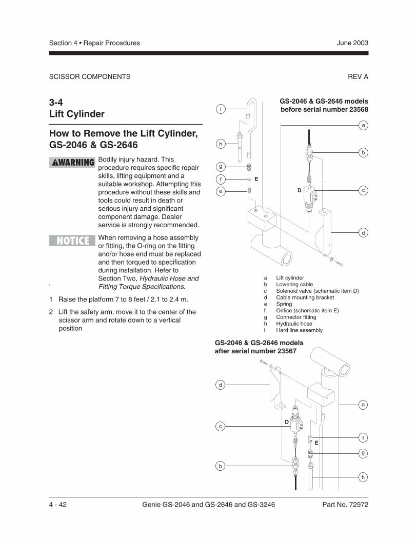
4 - 42 Genie GS-2046 and GS-2646 and GS-3246 Part No. 72972
June 2003Section 4 • Repair Procedures
REV A
3-4Lift Cylinder
How to Remove the Lift Cylinder,GS-2046 & GS-2646
Bodily injury hazard. Thisprocedure requires specific repairskills, lifting equipment and asuitable workshop. Attempting thisprocedure without these skills andtools could result in death orserious injury and significantcomponent damage. Dealerservice is strongly recommended.
When removing a hose assemblyor fitting, the O-ring on the fittingand/or hose end must be replacedand then torqued to specificationduring installation. Refer toSection Two, Hydraulic Hose andFitting Torque Specifications.
1 Raise the platform 7 to 8 feet / 2.1 to 2.4 m.
2 Lift the safety arm, move it to the center of thescissor arm and rotate down to a verticalposition
SCISSOR COMPONENTS
GS-2046 & GS-2646 modelsbefore serial number 23568
a Lift cylinderb Lowering cablec Solenoid valve (schematic item D)d Cable mounting brackete Springf Orifice (schematic item E)g Connector fittingh Hydraulic hosei Hard line assembly
GS-2046 & GS-2646 modelsafter serial number 23567
Part No. 72972 Genie GS-2046 and GS-2646 and GS-3246 4 - 43
June 2003 Section 4 • Repair Procedures
REV A
3 Lower the scissor arms onto the safety arm.
Crushing hazard. Keep handsclear of the safety arm whenlowering the platform.
4 Tag and disconnect the wiring from the solenoidat the barrel end of the lift cylinder.
5 Loosen the adjustment nuts on the solenoid,then disconnect the manual lowering cable fromthe solenoid.
During assembly, the manualplatform lowering cable needs tobe properly adjusted. Refer to 4-1,How to Adjust the Manual PlatformLowering Cable.
6 Remove the mounting fasteners from themanual lowering cable mounting bracket.Remove the bracket from the cylinder.
7 Before serial number 23568: Disconnect andplug the hydraulic hardline from the lift cylinder.Cap the fitting on the cylinder.After serial number 23567: Disconnect andplug the hydraulic hose from the lift cylinder.Cap the fitting on the cylinder.
Bodily injury hazard. Sprayinghydraulic oil can penetrate andburn skin. Loosen hydraulicconnections very slowly to allowthe oil pressure to dissipategradually. Do not allow oil to squirtor spray.
8 Before serial number 23568: Remove thehardline retaining strap from the cylinder.
9 Attach a lifting strap from an overhead crane orsimilar lifting device to the rod end of the liftcylinder for support.
10 Remove the external snap ring from the liftcylinder rod-end pivot pin. Use a soft metal driftto remove the pin.
Crushing hazard. The lift cylinderwill fall if not properly supported.
11 Lower the cylinder.
Component damage hazard. Becareful not to damage the levelsensor box, limit switch or levelsensor while lowering the cylinder.
12 Support and secure the entry ladder to anappropriate lifting device.
13 Remove the entry ladder mounting fasteners.Remove the entry ladder from the machine.
Crushing hazard. The entry laddermay become unbalanced and fallif not properly supported andsecured to the lifting device.
14 Attach a lifting strap from an overhead crane orsimilar lifting device to the barrel end of the liftcylinder for support.
15 Remove the external snap ring from the liftcylinder barrel-end pivot pin. Use a soft metaldrift to remove the pin.
Crushing hazard. The lift cylinderwill fall if not properly supported.
16 Support and secure the lift cylinder to anappropriate lifting device.
Crushing hazard. The lift cylindermay become unbalanced and fallif not properly supported andsecured to the lifting device.
17 Carefully pull the cylinder out the non-steer endof the machine through the scissor arms.
Component damage hazard. Becareful not to damage the valve orfittings on the cylinder whileremoving it from the machine.
SCISSOR COMPONENTS
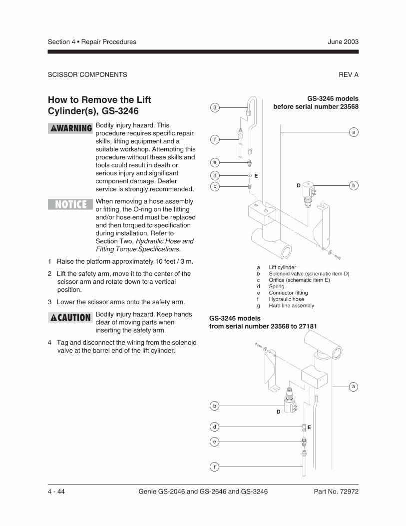
4 - 44 Genie GS-2046 and GS-2646 and GS-3246 Part No. 72972
June 2003Section 4 • Repair Procedures
REV A
GS-3246 modelsbefore serial number 23568
a Lift cylinderb Solenoid valve (schematic item D)c Orifice (schematic item E)d Springe Connector fittingf Hydraulic hoseg Hard line assembly
GS-3246 modelsfrom serial number 23568 to 27181
How to Remove the LiftCylinder(s), GS-3246
Bodily injury hazard. Thisprocedure requires specific repairskills, lifting equipment and asuitable workshop. Attempting thisprocedure without these skills andtools could result in death orserious injury and significantcomponent damage. Dealerservice is strongly recommended.
When removing a hose assemblyor fitting, the O-ring on the fittingand/or hose end must be replacedand then torqued to specificationduring installation. Refer toSection Two, Hydraulic Hose andFitting Torque Specifications.
1 Raise the platform approximately 10 feet / 3 m.
2 Lift the safety arm, move it to the center of thescissor arm and rotate down to a verticalposition.
3 Lower the scissor arms onto the safety arm.
Bodily injury hazard. Keep handsclear of moving parts wheninserting the safety arm.
4 Tag and disconnect the wiring from the solenoidvalve at the barrel end of the lift cylinder.
SCISSOR COMPONENTS
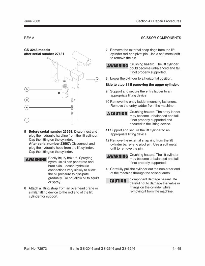
Part No. 72972 Genie GS-2046 and GS-2646 and GS-3246 4 - 45
June 2003 Section 4 • Repair Procedures
REV A SCISSOR COMPONENTS
GS-3246 modelsafter serial number 27181
5 Before serial number 23568: Disconnect andplug the hydraulic hardline from the lift cylinder.Cap the fitting on the cylinder.After serial number 23567: Disconnect andplug the hydraulic hose from the lift cylinder.Cap the fitting on the cylinder.
Bodily injury hazard. Sprayinghydraulic oil can penetrate andburn skin. Loosen hydraulicconnections very slowly to allowthe oil pressure to dissipategradually. Do not allow oil to squirtor spray.
6 Attach a lifting strap from an overhead crane orsimilar lifting device to the rod end of the liftcylinder for support.
7 Remove the external snap rings from the liftcylinder rod-end pivot pin. Use a soft metal driftto remove the pin.
Crushing hazard. The lift cylindercould become unbalanced and fallif not properly supported.
8 Lower the cylinder to a horizontal position.
Skip to step 11 if removing the upper cylinder.
9 Support and secure the entry ladder to anappropriate lifting device.
10 Remove the entry ladder mounting fasteners.Remove the entry ladder from the machine.
Crushing hazard. The entry laddermay become unbalanced and fallif not properly supported andsecured to the lifting device.
11 Support and secure the lift cylinder to anappropriate lifting device.
12 Remove the external snap ring from the liftcylinder barrel-end pivot pin. Use a soft metaldrift to remove the pin.
Crushing hazard. The lift cylindermay become unbalanced and fallif not properly supported.
13 Carefully pull the cylinder out the non-steer endof the machine through the scissor arms.
Component damage hazard. Becareful not to damage the valve orfittings on the cylinder whileremoving it from the machine.
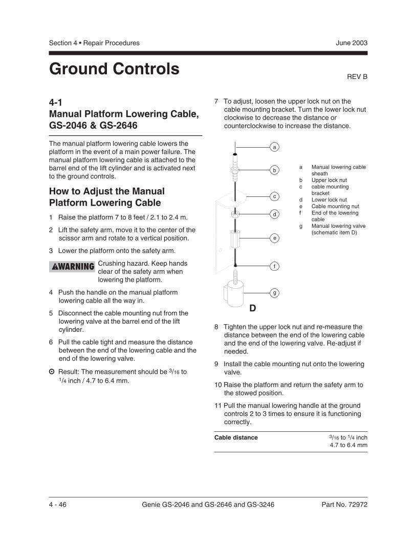
4 - 46 Genie GS-2046 and GS-2646 and GS-3246 Part No. 72972
June 2003Section 4 • Repair Procedures
REV BGround Controls
4-1Manual Platform Lowering Cable,GS-2046 & GS-2646
The manual platform lowering cable lowers theplatform in the event of a main power failure. Themanual platform lowering cable is attached to thebarrel end of the lift cylinder and is activated nextto the ground controls.
How to Adjust the ManualPlatform Lowering Cable1 Raise the platform 7 to 8 feet / 2.1 to 2.4 m.
2 Lift the safety arm, move it to the center of thescissor arm and rotate to a vertical position.
3 Lower the platform onto the safety arm.
Crushing hazard. Keep handsclear of the safety arm whenlowering the platform.
4 Push the handle on the manual platformlowering cable all the way in.
5 Disconnect the cable mounting nut from thelowering valve at the barrel end of the liftcylinder.
6 Pull the cable tight and measure the distancebetween the end of the lowering cable and theend of the lowering valve.
Result: The measurement should be 3/16 to1/4 inch / 4.7 to 6.4 mm.
a Manual lowering cablesheath
b Upper lock nutc cable mounting
bracketd Lower lock nute Cable mounting nutf End of the lowering
cableg Manual lowering valve
(schematic item D)
7 To adjust, loosen the upper lock nut on thecable mounting bracket. Turn the lower lock nutclockwise to decrease the distance orcounterclockwise to increase the distance.
c
a
b
g
d
e
f
D
8 Tighten the upper lock nut and re-measure thedistance between the end of the lowering cableand the end of the lowering valve. Re-adjust ifneeded.
9 Install the cable mounting nut onto the loweringvalve.
10 Raise the platform and return the safety arm tothe stowed position.
11 Pull the manual lowering handle at the groundcontrols 2 to 3 times to ensure it is functioningcorrectly.
Cable distance 3/16 to 1/4 inch4.7 to 6.4 mm
Part No. 72972 Genie GS-2046 and GS-2646 and GS-3246 4 - 47
June 2003 Section 4 • Repair Procedures
REV B GROUND CONTROLS
4-2Manual Platform Lowering,GS-3246
When activated, the manual platform loweringbutton lowers the platform in the event of a mainpower failure. The manual platform lowering buttonis located at the ground control panel. There is noadjustment required.
Before serial number 49200, two 12V batteries arewired in series supplying 24V to the manualplatform lowering button. The batteries are locatedinside the ground control panel.
How to Replace the ManualPlatform Lowering Batteries(before serial number 49200)1 Remove the ground control cover retaining
fasteners. Remove the cover.
2 Tag and disconnect the wires from the batteryto be removed.
3 Remove the battery from the machine.
4 Install the new battery and connect the wires.
5 Install the ground control cover.
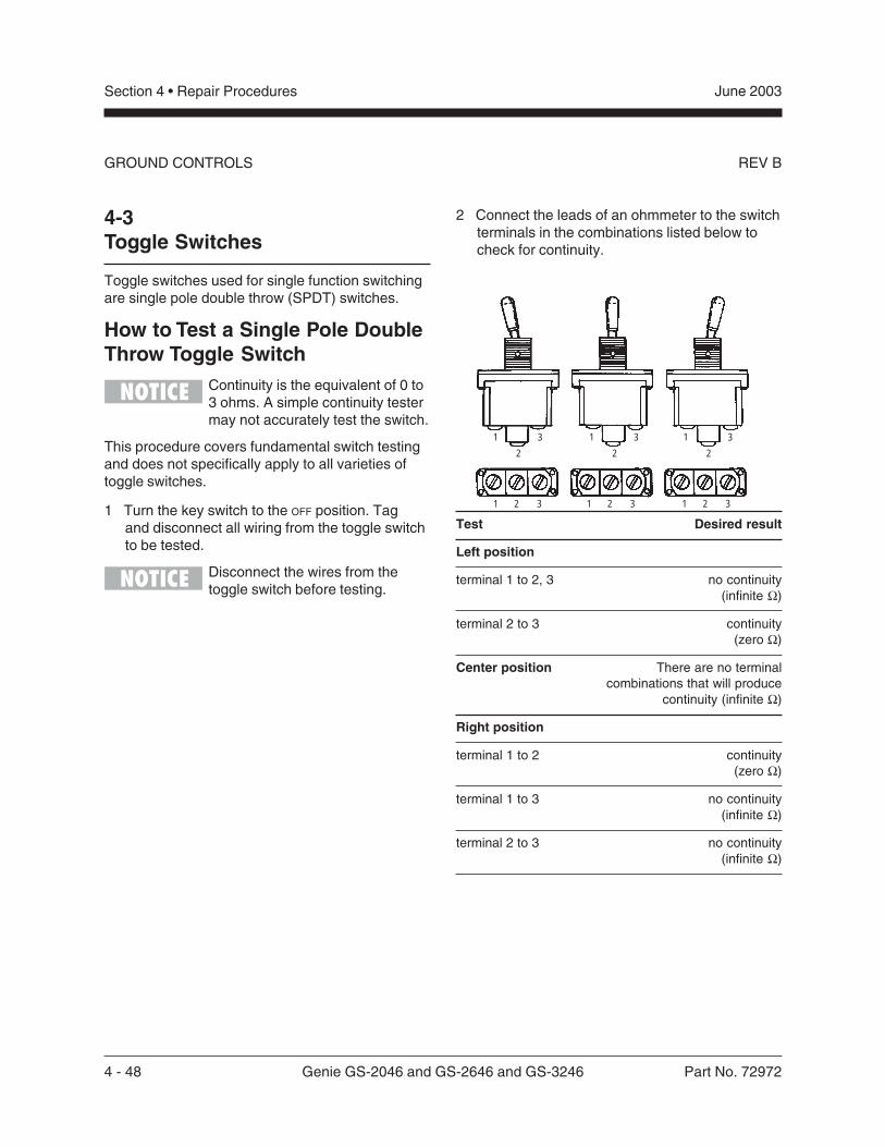
4 - 48 Genie GS-2046 and GS-2646 and GS-3246 Part No. 72972
June 2003Section 4 • Repair Procedures
REV BGROUND CONTROLS
1
2
3
4 5 6
1 2 3
1
2
3 1
2
3
1 2 3 1 2 3
1 2 3 1 2 3 1 2 3
4 5 6 4 5 6
4-3Toggle Switches
Toggle switches used for single function switchingare single pole double throw (SPDT) switches.
How to Test a Single Pole DoubleThrow Toggle Switch
Continuity is the equivalent of 0 to3 ohms. A simple continuity testermay not accurately test the switch.
This procedure covers fundamental switch testingand does not specifically apply to all varieties oftoggle switches.
1 Turn the key switch to the OFF position. Tagand disconnect all wiring from the toggle switchto be tested.
Disconnect the wires from thetoggle switch before testing.
2 Connect the leads of an ohmmeter to the switchterminals in the combinations listed below tocheck for continuity.
Test Desired result
Left position
terminal 1 to 2, 3 no continuity(infinite Ω)
terminal 2 to 3 continuity(zero Ω)
Center position There are no terminalcombinations that will produce
continuity (infinite Ω)
Right position
terminal 1 to 2 continuity(zero Ω)
terminal 1 to 3 no continuity(infinite Ω)
terminal 2 to 3 no continuity(infinite Ω)
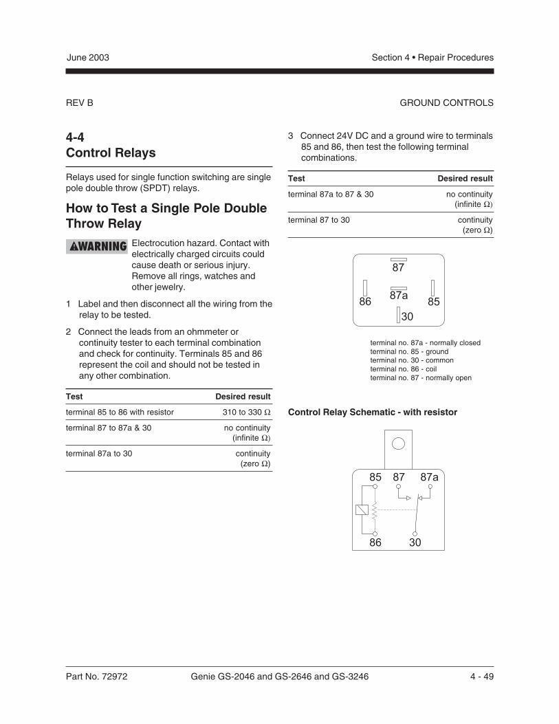
Part No. 72972 Genie GS-2046 and GS-2646 and GS-3246 4 - 49
June 2003 Section 4 • Repair Procedures
REV B
4-4Control Relays
Relays used for single function switching are singlepole double throw (SPDT) relays.
How to Test a Single Pole DoubleThrow Relay
Electrocution hazard. Contact withelectrically charged circuits couldcause death or serious injury.Remove all rings, watches andother jewelry.
1 Label and then disconnect all the wiring from therelay to be tested.
2 Connect the leads from an ohmmeter orcontinuity tester to each terminal combinationand check for continuity. Terminals 85 and 86represent the coil and should not be tested inany other combination.
Test Desired result
terminal 85 to 86 with resistor 310 to 330 Ω
terminal 87 to 87a & 30 no continuity(infinite Ω)
terminal 87a to 30 continuity(zero Ω)
3 Connect 24V DC and a ground wire to terminals85 and 86, then test the following terminalcombinations.
Test Desired result
terminal 87a to 87 & 30 no continuity(infinite Ω)
terminal 87 to 30 continuity(zero Ω)
terminal no. 87a - normally closedterminal no. 85 - groundterminal no. 30 - commonterminal no. 86 - coilterminal no. 87 - normally open
Control Relay Schematic - with resistor
GROUND CONTROLS
4 - 50 Genie GS-2046 and GS-2646 and GS-3246 Part No. 72972
June 2003Section 4 • Repair Procedures
REV BGROUND CONTROLS
4-5Tilt Level Sensor(before serial number 50444)
How to Install and Calibrate the2° Level SensorThis procedure is for models equipped with a2° side / 3° front / 5° rear level sensor.
Tip-over hazard. Failure to installor calibrate the tilt level sensor asinstructed will compromisemachine stability and cause themachine to tip over, resulting indeath or serious injury. Do notinstall or calibrate the level sensorother than specified in thisprocedure.
Perform this procedure with themachine on a firm, level surfacethat is free of obstructions.
1 Remove the platform controls from the platform.
2 Turn the key switch to platform control and pullout the red Emergency Stop buttons to the ON
position at both the ground and platformcontrols.
3 Block the wheels at the non-steer end of themachine.
4 Center a lifting jack under the drive chassis atthe steer end of the machine.
5 Raise the machine approximately2 inches / 5 cm.
6 Place a 1.27 x 6 x 6 inch / 23.1 mm x15 cm x 15 cm thick steel block under bothwheels at the steer end of the machine.
7 Lower the machine onto the blocks.
8 Raise the platform 7 to 8 feet / 2.1 to 2.4 m.
9 Lift the safety arm, move it to the center of thescissor arm and rotate down to a verticalposition.
10 Lower the scissor arms onto the safety arm.
Crushing hazard. Keep handsclear of the safety arm whenlowering the platform.
11 Remove the tilt level sensor box cover retainingfasteners. Remove the cover.
The tilt level sensor box is locatedon top of the chassis at the steerend of the machine.
If you are not installing a new level sensor,proceed to step 20.
12 Turn the key switch to the OFF position and pushin the red Emergency Stop button to the OFF
position at the ground controls.
13 Tag and disconnect the wiring harness from thelevel sensor, limit switch and alarm.
14 Remove the tilt level sensor box retainingfasteners. Remove the tilt level sensor box fromthe machine.
15 Remove the tilt level sensor retaining fasteners.Remove the tilt level sensor from the levelsensor box.
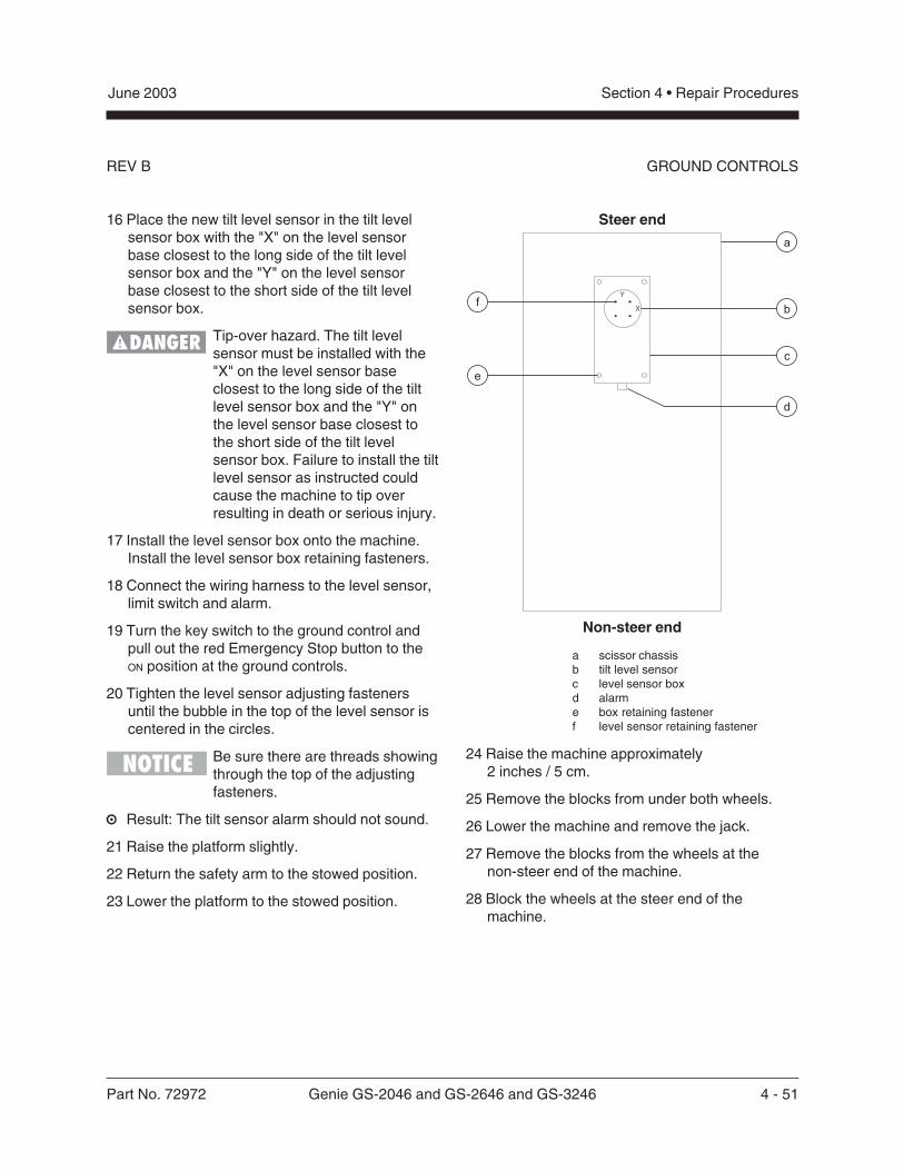
Part No. 72972 Genie GS-2046 and GS-2646 and GS-3246 4 - 51
June 2003 Section 4 • Repair Procedures
REV B GROUND CONTROLS
16 Place the new tilt level sensor in the tilt levelsensor box with the "X" on the level sensorbase closest to the long side of the tilt levelsensor box and the "Y" on the level sensorbase closest to the short side of the tilt levelsensor box.
Tip-over hazard. The tilt levelsensor must be installed with the"X" on the level sensor baseclosest to the long side of the tiltlevel sensor box and the "Y" onthe level sensor base closest tothe short side of the tilt levelsensor box. Failure to install the tiltlevel sensor as instructed couldcause the machine to tip overresulting in death or serious injury.
17 Install the level sensor box onto the machine.Install the level sensor box retaining fasteners.
18 Connect the wiring harness to the level sensor,limit switch and alarm.
19 Turn the key switch to the ground control andpull out the red Emergency Stop button to theON position at the ground controls.
20 Tighten the level sensor adjusting fastenersuntil the bubble in the top of the level sensor iscentered in the circles.
Be sure there are threads showingthrough the top of the adjustingfasteners.
Result: The tilt sensor alarm should not sound.
21 Raise the platform slightly.
22 Return the safety arm to the stowed position.
23 Lower the platform to the stowed position.
Steer end
Non-steer end
a scissor chassisb tilt level sensorc level sensor boxd alarme box retaining fastenerf level sensor retaining fastener
24 Raise the machine approximately2 inches / 5 cm.
25 Remove the blocks from under both wheels.
26 Lower the machine and remove the jack.
27 Remove the blocks from the wheels at thenon-steer end of the machine.
28 Block the wheels at the steer end of themachine.
X
Y
f
e
a
b
d
c
4 - 52 Genie GS-2046 and GS-2646 and GS-3246 Part No. 72972
June 2003Section 4 • Repair Procedures
REV BGROUND CONTROLS
29 Center a lifting jack under the drive chassis atthe non-steer end of the machine.
30 Raise the machine approximately5 inches / 13 cm.
31 Place a 6.63 x 6 x 6 inch / 12.1 x 15 x 15 cmthick steel block under both wheels at thenon-steer end of the machine.
32 Lower the machine onto the blocks.
33 Models before serial number 48817: Raisethe platform 7 to 8 feet / 2.1 to 2.1 m.
Result: The tilt sensor alarm should sound.
Result: If the tilt sensor alarm does not sound,adjust the tilt level sensor until the alarm justbegins to sound OR the down limit switch mayneed to be adjusted.
CE models: When the platform israised 7 to 8 feet / 2.1 to 2.4 mfrom the ground, an alarm shouldsound and the lift and drivefunctions should not operate.
Models after serial number 48816: Raise theplatform 7 to 8 feet / 2.1 to 2.4 m.
Result: The platform should stop and an alarmshould sound.
Result: If the platform does not stop or the tiltsensor alarm does not sound, adjust the tiltlevel sensor until the alarm just begins to soundOR the down limit switch may need to beadjusted.
34 Lower the platform to the stowed position.
35 Raise the machine approximately5 inches / 13 cm.
36 Remove the blocks from under both wheels.
37 Lower the machine and remove the jack.
38 Remove the blocks from the wheels at the steerend of the machine.
39 Center a lifting jack under the drive chassis atthe ground controls side of the machine.
40 Raise the machine approximately2 inches / 5 cm.
41 Place a 1.36 x 6 x 6 inch / 21.5 mm x15 cm x 15 cm thick steel block under bothwheels at the ground controls side of themachine.
42 Lower the machine onto the blocks.
43 Raise the platform 7 to 8 feet / 2.1 to 2.4 m.
Result: The tilt sensor alarm should sound.
44 Adjust the tilt level sensor retaining fastenersjust until the tilt sensor alarm does not sound.
45 Lower the platform to the stowed position.
46 Raise the machine approximately2 inches / 5 cm.
47 Remove the blocks from under both wheels.
48 Lower the machine and remove the jack.
49 Center a lifting jack under the drive chassis atthe battery pack side of the machine.
50 Raise the machine approximately2 inches / 5 cm.
Part No. 72972 Genie GS-2046 and GS-2646 and GS-3246 4 - 53
June 2003 Section 4 • Repair Procedures
REV B
51 Place a 1.57 x 6 x 6 inch / 25 mm x15 cm x 15 cm thick steel block under bothwheels at the battery pack side of the machine.
52 Lower the machine onto the blocks.
53 Models before serial number 48817: Raisethe platform 7 to 8 feet / 2.1 to 2.1 m.
Result: The tilt sensor alarm should sound.
Result: If the tilt sensor alarm does not sound,adjust the tilt level sensor until the alarm justbegins to sound OR the down limit switch mayneed to be adjusted.
CE models: When the platform israised 7 to 8 feet / 2.1 to 2.4 mfrom the ground, an alarm shouldsound and the lift and drivefunctions should not operate.
Models after serial number 48816: Raise theplatform 7 to 8 feet / 2.1 to 2.4 m.
Result: The platform should stop and an alarmshould sound.
Result: If the platform does not stop or the tiltsensor alarm does not sound, adjust the tiltlevel sensor until the alarm just begins to soundOR the down limit switch may need to beadjusted.
54 Lift the safety arm, move it to the center of thescissor arm and rotate down to a verticalposition.
55 Lower the scissor arms onto the safety arm.
Crushing hazard. Keep handsclear of the safety arm whenlowering the platform.
56 Install the tilt level sensor box cover.
57 Raise the platform slightly.
58 Return the safety arm to the stowed position.
59 Lower the platform to the stowed position.
60 Raise the machine approximately2 inches / 5 cm.
61 Remove the blocks from under both wheels.
62 Lower the machine and remove the jack.
GROUND CONTROLS
4 - 54 Genie GS-2046 and GS-2646 and GS-3246 Part No. 72972
June 2003Section 4 • Repair Procedures
REV B
4-6Tilt Level Sensor(after serial number 50443)
How to Install and Calibrate the2° Level SensorThis procedure is for models equipped with a2° side / 3° front / 3° rear level sensor.
Tip-over hazard. Failure to installor calibrate the tilt level sensor asinstructed will compromisemachine stability and cause themachine to tip over, resulting indeath or serious injury. Do notinstall or calibrate the level sensorother than specified in thisprocedure.
Perform this procedure with themachine on a firm, level surfacethat is free of obstructions.
1 Remove the platform controls from the platform.
2 Turn the key switch to platform control and pullout the red Emergency Stop buttons to the ON
position at both the ground and platformcontrols.
3 Raise the platform 7 to 8 feet / 2.1 to 2.4 m.
4 Lift the safety arm, move it to the center of thescissor arm and rotate down to a verticalposition.
5 Lower the platform onto the safety arm.
Crushing hazard. Keep handsclear of the safety arm whenlowering the platform.
6 Remove the tilt level sensor box cover retainingfasteners. Remove the cover.
The tilt level sensor box is locatedon top of the chassis at the steerend of the machine.
If you are not installing a new level sensor,proceed to step 15.
7 Turn the key switch to the OFF position and pushin the red Emergency Stop button to the OFF
position at the ground controls.
8 Tag and disconnect the wiring harness from thelevel sensor, limit switch and alarm.
9 Remove the tilt level sensor box retainingfasteners. Remove the tilt level sensor box fromthe machine.
10 Remove the tilt level sensor retaining fasteners.Remove the tilt level sensor from the levelsensor box.
GROUND CONTROLS
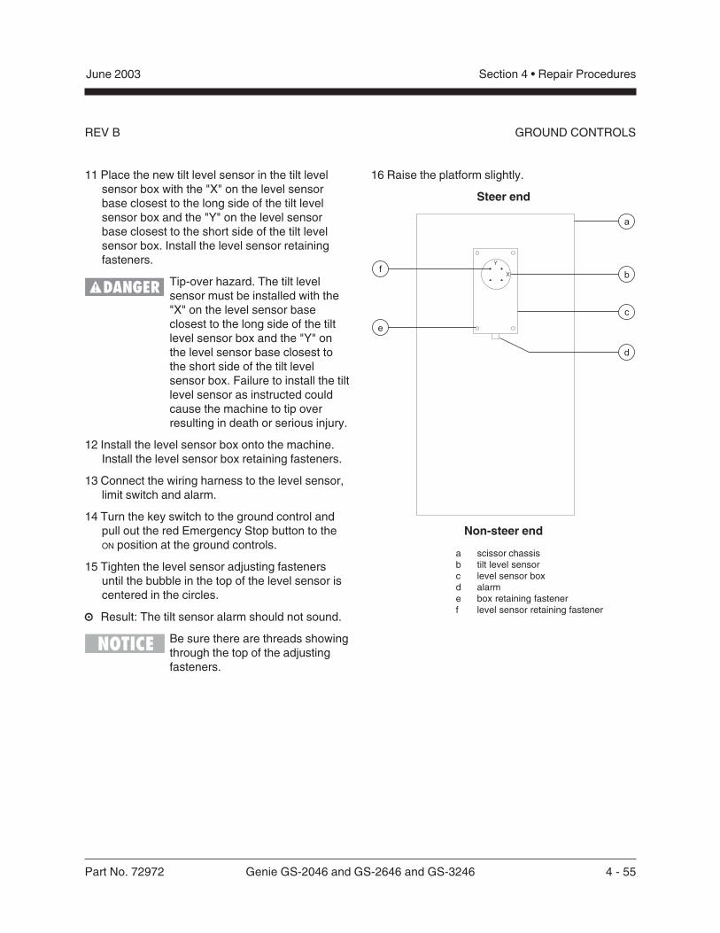
Part No. 72972 Genie GS-2046 and GS-2646 and GS-3246 4 - 55
June 2003 Section 4 • Repair Procedures
REV B
11 Place the new tilt level sensor in the tilt levelsensor box with the "X" on the level sensorbase closest to the long side of the tilt levelsensor box and the "Y" on the level sensorbase closest to the short side of the tilt levelsensor box. Install the level sensor retainingfasteners.
Tip-over hazard. The tilt levelsensor must be installed with the"X" on the level sensor baseclosest to the long side of the tiltlevel sensor box and the "Y" onthe level sensor base closest tothe short side of the tilt levelsensor box. Failure to install the tiltlevel sensor as instructed couldcause the machine to tip overresulting in death or serious injury.
12 Install the level sensor box onto the machine.Install the level sensor box retaining fasteners.
13 Connect the wiring harness to the level sensor,limit switch and alarm.
14 Turn the key switch to the ground control andpull out the red Emergency Stop button to theON position at the ground controls.
15 Tighten the level sensor adjusting fastenersuntil the bubble in the top of the level sensor iscentered in the circles.
Result: The tilt sensor alarm should not sound.
Be sure there are threads showingthrough the top of the adjustingfasteners.
16 Raise the platform slightly.
Steer end
Non-steer end
a scissor chassisb tilt level sensorc level sensor boxd alarme box retaining fastenerf level sensor retaining fastener
GROUND CONTROLS
X
Y
f
e
a
b
d
c
4 - 56 Genie GS-2046 and GS-2646 and GS-3246 Part No. 72972
June 2003Section 4 • Repair Procedures
REV B
17 Return the safety arm to the stowed position.
18 Lower the platform to the stowed position.
19 Center a lifting jack under the drive chassis atthe ground controls side of the machine.
20 Raise the machine approximately2 inches / 5 cm.
21 Place a 1.36 x 6 x 6 inch / 21.6 mm x 15 cm x15 cm thick steel block under both wheels atthe ground controls side of the machine.
22 Lower the machine onto the blocks.
23 Raise the platform 7 to 8 feet / 2.1 to 2.4 m.
Result: The tilt sensor alarm should not sound.
Result: The tilt sensor alarm does sound. Adjustthe tilt level sensor retaining fasteners just untilthe tilt sensor alarm does not sound.
24 Lower the platform to the stowed position.
25 Raise the machine approximately2 inches / 5 cm.
26 Remove the blocks from under both wheels.
27 Lower the machine and remove the jack.
28 Center a lifting jack under the drive chassis atthe battery pack side of the machine.
29 Raise the machine approximately2 inches / 5 cm.
30 Place a 1.57 x 6 x 6 inch / 24.9 mm x 15 cm x15 cm thick steel block under both wheels atthe ground controls side of the machine.
31 Lower the machine onto the blocks.
32 Models before serial number 48817: Raisethe platform 7 to 8 feet / 2.1 to 2.4 m.
Result: The tilt sensor alarm should sound.
Result: The tilt sensor alarm does not sound.Adjust the tilt level sensor until the alarm justbegins to sound OR the down limit switch mayneed to be adjusted.
CE models: When the platform israised 7 to 8 feet / 2.1 to 2.4 mfrom the ground, an alarm shouldsound and the lift and drivefunctions should not operate.
Models after serial number 48816: Raise theplatform 7 to 8 feet / 2.1 to 2.4 m.
Result: The platform should stop and an alarmshould sound.
Result: The platform does not stop or the tiltsensor alarm does not sound. Adjust the tiltlevel sensor until the alarm just begins to soundOR the down limit switch may need to beadjusted.
33 Lift the safety arm, move it to the center of thescissor arm and rotate down to a verticalposition.
34 Lower the scissor arms onto the safety arm.
Crushing hazard. Keep handsclear of the safety arm whenlowering the platform.
35 Install the tilt level sensor box cover.
36 Raise the platform 7 to 8 feet / 2.1 to 2.4 m.
GROUND CONTROLS
Part No. 72972 Genie GS-2046 and GS-2646 and GS-3246 4 - 57
June 2003 Section 4 • Repair Procedures
REV B GROUND CONTROLS
37 Return the safety arm to the stowed position.
38 Lower the platform to the stowed position.
39 Raise the machine approximately2 inches / 5 cm.
40 Remove the blocks from under both wheels.
41 Lower the machine and remove the jack.
4 - 58 Genie GS-2046 and GS-2646 and GS-3246 Part No. 72972
June 2003Section 4 • Repair Procedures
REV AHydraulic Pump
5-1Function Pump
The hydraulic pump is attached to an electricmotor which makes up the Hydraulic Power Unit.
How to Test the Hydraulic PumpWhen removing a hose assemblyor fitting, the O-ring on the fittingand/or hose end must be replacedand then torqued to specificationduring installation. Refer toSection Two, Hydraulic Hose andFitting Torque Specifications.
1 Disconnect and plug the high pressurehydraulic hose from the hydraulic pump.
Bodily injury hazard. Sprayinghydraulic oil can penetrate andburn skin. Loosen hydraulicconnections very slowly to allowthe oil pressure to dissipategradually. Do not allow oil to squirtor spray.
2 Connect a 0 to 5000 psi / 0 to 350 bar pressuregauge to the high pressure port on the pump.
3 Turn the key switch to ground control and pullout the Emergency Stop button to the ON
position at both the ground and platformcontrols.
4 Activate the platform up function from theground controls.
Result: If the pressure gauge reads3200 psi / 221 bar, immediately stop. The pumpis good.
Result: If pressure fails to reach3200 psi / 221 bar, the pump is bad and willneed to be serviced or replaced.
Component damage hazard.There is no relief valve in thehydraulic pump and the pump canbe damaged if the pressure isallowed to exceed 3200 psi / 221bar. When testing the pump,activate the pump in one secondintervals until 3200 psi / 221 bar isconfirmed. Do not over-pressurizethe pump.
5 Remove the pressure gauge and reconnect thehydraulic hose.
Bodily injury hazard. Sprayinghydraulic oil can penetrate andburn skin. Loosen hydraulicconnections very slowly to allowthe oil pressure to dissipategradually. Do not allow oil to squirtor spray.
Part No. 72972 Genie GS-2046 and GS-2646 and GS-3246 4 - 59
June 2003 Section 4 • Repair Procedures
REV A
How to Remove theHydraulic Pump
When removing a hose assemblyor fitting, the O-ring on the fittingand/or hose end must be replacedand then torqued to specificationduring installation. Refer toSection Two, Hydraulic Hose andFitting Torque Specifications.
1 Remove the mounting fasteners from thehydraulic filter bracket at the function manifold.Move the filter off to the side.
2 Tag, disconnect and plug the hydraulic hoseson the pump. Cap the fittings on the pump.
Bodily injury hazard. Sprayinghydraulic oil can penetrate andburn skin. Loosen hydraulicconnections very slowly to allowthe oil pressure to dissipategradually. Do not allow oil to squirtor spray.
3 Remove the pump mounting bolts. Carefullyremove the pump.
HYDRAULIC PUMP
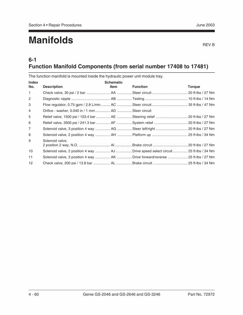
4 - 60 Genie GS-2046 and GS-2646 and GS-3246 Part No. 72972
June 2003Section 4 • Repair Procedures
REV B
6-1Function Manifold Components (from serial number 17408 to 17481)
Manifolds
Index SchematicNo. Description Item Function Torque
1 Check valve, 30 psi / 2 bar ........................ AA ...............Steer circuit .................................... 20 ft-lbs / 27 Nm
2 Diagnostic nipple ....................................... AB ...............Testing ........................................... 10 ft-lbs / 14 Nm
3 Flow regulator, 0.75 gpm / 2.8 L/min ......... AC ...............Steer circuit .................................... 35 ft-lbs / 47 Nm
4 Orifice - washer, 0.040 in / 1 mm............... AD ...............Steer circuit
5 Relief valve, 1500 psi / 103.4 bar .............. AE ...............Steering relief ................................ 20 ft-lbs / 27 Nm
6 Relief valve, 3500 psi / 241.3 bar .............. AF ................System relief .................................. 20 ft-lbs / 27 Nm
7 Solenoid valve, 3 position 4 way ............... AG ...............Steer left/right ................................ 20 ft-lbs / 27 Nm
8 Solenoid valve, 2 position 4 way ............... AH ...............Platform up .................................... 25 ft-lbs / 34 Nm
9 Solenoid valve,2 position 2 way, N.O. ............................... AI .................Brake circuit ................................... 20 ft-lbs / 27 Nm
10 Solenoid valve, 2 position 4 way ............... AJ ................Drive speed select circuit ............... 25 ft-lbs / 34 Nm
11 Solenoid valve, 3 position 4 way ............... AK ...............Drive forward/reverse .................... 25 ft-lbs / 27 Nm
12 Check valve, 200 psi / 13.8 bar ................. AL ................Brake circuit ................................... 25 ft-lbs / 34 Nm
The function manifold is mounted inside the hydraulic power unit module tray.
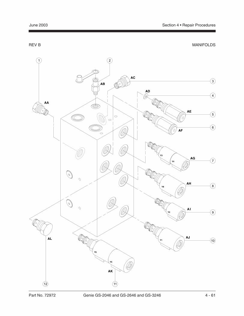
Part No. 72972 Genie GS-2046 and GS-2646 and GS-3246 4 - 61
June 2003 Section 4 • Repair Procedures
REV B MANIFOLDS
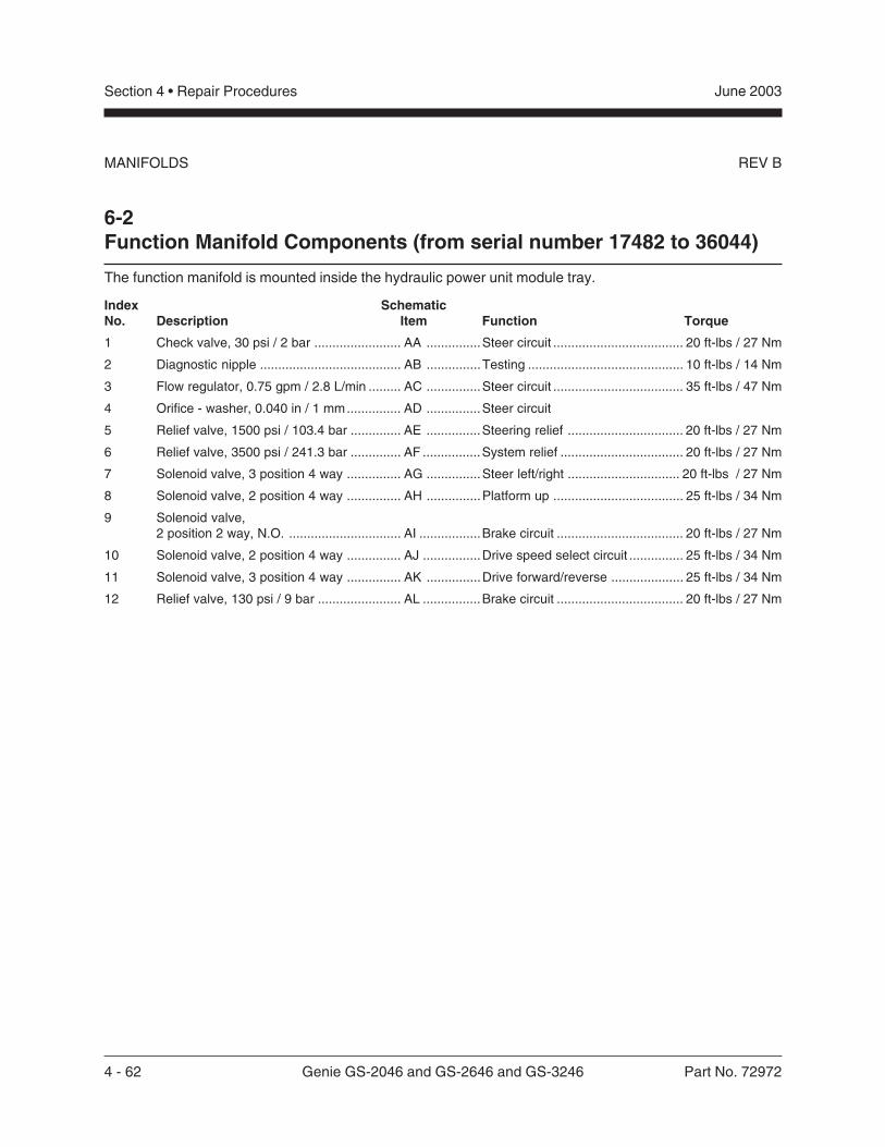
4 - 62 Genie GS-2046 and GS-2646 and GS-3246 Part No. 72972
June 2003Section 4 • Repair Procedures
REV BMANIFOLDS
Index SchematicNo. Description Item Function Torque
1 Check valve, 30 psi / 2 bar ........................ AA ...............Steer circuit .................................... 20 ft-lbs / 27 Nm
2 Diagnostic nipple ....................................... AB ...............Testing ........................................... 10 ft-lbs / 14 Nm
3 Flow regulator, 0.75 gpm / 2.8 L/min ......... AC ...............Steer circuit .................................... 35 ft-lbs / 47 Nm
4 Orifice - washer, 0.040 in / 1 mm............... AD ...............Steer circuit
5 Relief valve, 1500 psi / 103.4 bar .............. AE ...............Steering relief ................................ 20 ft-lbs / 27 Nm
6 Relief valve, 3500 psi / 241.3 bar .............. AF ................System relief .................................. 20 ft-lbs / 27 Nm
7 Solenoid valve, 3 position 4 way ............... AG ...............Steer left/right ............................... 20 ft-lbs / 27 Nm
8 Solenoid valve, 2 position 4 way ............... AH ...............Platform up .................................... 25 ft-lbs / 34 Nm
9 Solenoid valve,2 position 2 way, N.O. ............................... AI .................Brake circuit ................................... 20 ft-lbs / 27 Nm
10 Solenoid valve, 2 position 4 way ............... AJ ................Drive speed select circuit ............... 25 ft-lbs / 34 Nm
11 Solenoid valve, 3 position 4 way ............... AK ...............Drive forward/reverse .................... 25 ft-lbs / 34 Nm
12 Relief valve, 130 psi / 9 bar ....................... AL ................Brake circuit ................................... 20 ft-lbs / 27 Nm
6-2Function Manifold Components (from serial number 17482 to 36044)
The function manifold is mounted inside the hydraulic power unit module tray.
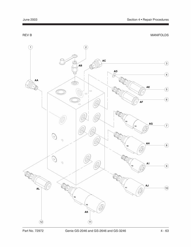
Part No. 72972 Genie GS-2046 and GS-2646 and GS-3246 4 - 63
June 2003 Section 4 • Repair Procedures
REV B MANIFOLDS
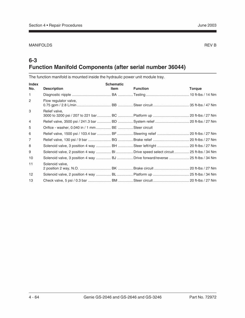
4 - 64 Genie GS-2046 and GS-2646 and GS-3246 Part No. 72972
June 2003Section 4 • Repair Procedures
REV B
Index SchematicNo. Description Item Function Torque
1 Diagnostic nipple ....................................... BA ...............Testing ........................................... 10 ft-lbs / 14 Nm
2 Flow regulator valve,0.75 gpm / 2.8 L/min .................................. BB ...............Steer circuit .................................... 35 ft-lbs / 47 Nm
3 Relief valve,3000 to 3200 psi / 207 to 221 bar .............. BC ...............Platform up .................................... 20 ft-lbs / 27 Nm
4 Relief valve, 3500 psi / 241.3 bar .............. BD ...............System relief .................................. 20 ft-lbs / 27 Nm
5 Orifice - washer, 0.040 in / 1 mm............... BE ...............Steer circuit
6 Relief valve, 1500 psi / 103.4 bar .............. BF ................Steering relief ................................ 20 ft-lbs / 27 Nm
7 Relief valve, 130 psi / 9 bar ....................... BG ...............Brake relief .................................... 20 ft-lbs / 27 Nm
8 Solenoid valve, 3 position 4 way ............... BH ...............Steer left/right ................................ 20 ft-lbs / 27 Nm
9 Solenoid valve, 2 position 4 way ............... BI .................Drive speed select circuit ............... 25 ft-lbs / 34 Nm
10 Solenoid valve, 3 position 4 way ............... BJ ................Drive forward/reverse .................... 25 ft-lbs / 34 Nm
11 Solenoid valve,2 position 2 way, N.O. ............................... BK ...............Brake circuit ................................... 20 ft-lbs / 27 Nm
12 Solenoid valve, 2 position 4 way ............... BL ................Platform up .................................... 25 ft-lbs / 34 Nm
13 Check valve, 5 psi / 0.3 bar ....................... BM ...............Steer circuit .................................... 20 ft-lbs / 27 Nm
6-3Function Manifold Components (after serial number 36044)
The function manifold is mounted inside the hydraulic power unit module tray.
MANIFOLDS
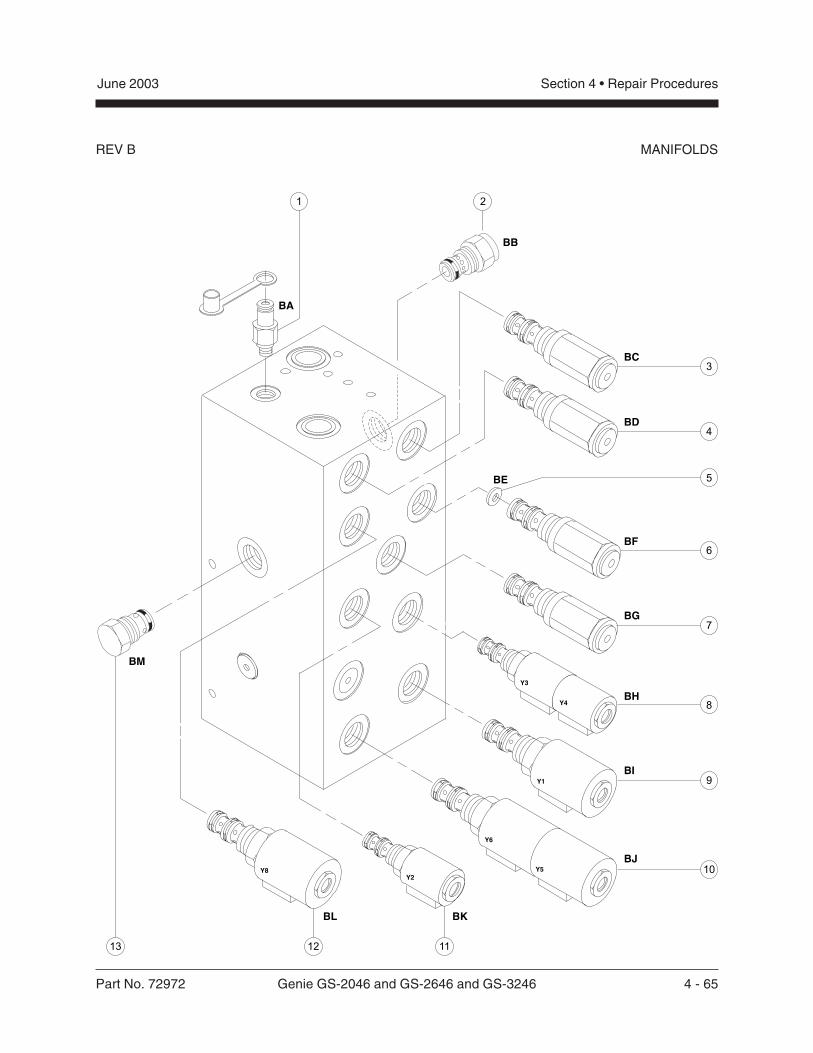
Part No. 72972 Genie GS-2046 and GS-2646 and GS-3246 4 - 65
June 2003 Section 4 • Repair Procedures
REV B MANIFOLDS
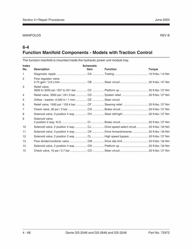
4 - 66 Genie GS-2046 and GS-2646 and GS-3246 Part No. 72972
June 2003Section 4 • Repair Procedures
REV B
Index SchematicNo. Description Item Function Torque
1 Diagnostic nipple ....................................... CA ...............Testing ........................................... 10 ft-lbs / 14 Nm
2 Flow regulator valve,0.75 gpm / 2.8 L/min .................................. CB ...............Steer circuit .................................... 35 ft-lbs / 47 Nm
3 Relief valve,3000 to 3200 psi / 207 to 221 bar .............. CC ...............Platform up .................................... 20 ft-lbs / 27 Nm
4 Relief valve, 3500 psi / 241.3 bar .............. CD ...............System relief .................................. 20 ft-lbs / 27 Nm
5 Orifice - washer, 0.040 in / 1 mm............... CE ...............Steer circuit
6 Relief valve, 1500 psi / 103.4 bar .............. CF ...............Steering relief ................................ 20 ft-lbs / 27 Nm
7 Check valve, 30 psi / 2 bar ........................ CG ...............Brake circuit ................................... 20 ft-lbs / 27 Nm
8 Solenoid valve, 3 position 4 way ............... CH ...............Steer left/right ................................ 20 ft-lbs / 27 Nm
9 Solenoid valve,2 position 2 way, N.O. ............................... CI .................Brake circuit ................................... 20 ft-lbs / 27 Nm
10 Solenoid valve, 2 position 4 way ............... CJ ................Drive speed select circuit ............... 25 ft-lbs / 34 Nm
11 Solenoid valve, 3 position 4 way ............... CK ...............Drive forward/reverse .................... 25 ft-lbs / 34 Nm
12 Solenoid valve, 2 position 2 way ............... CL ................High speed bypass ........................ 20 ft-lbs / 27 Nm
13 Flow divider/combiner valve ...................... CM ...............Drive slip limit ................................ 25 ft-lbs / 34 Nm
14 Solenoid valve, 2 position 4 way ............... CN ...............Platform up .................................... 25 ft-lbs / 34 Nm
15 Check valve, 10 psi / 0.7 bar ..................... CO ...............Steer circuit .................................... 20 ft-lbs / 27 Nm
6-4Function Manifold Components - Models with Traction Control
The function manifold is mounted inside the hydraulic power unit module tray.
MANIFOLDS
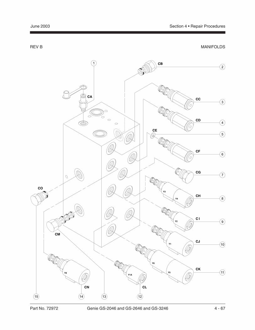
Part No. 72972 Genie GS-2046 and GS-2646 and GS-3246 4 - 67
June 2003 Section 4 • Repair Procedures
REV B MANIFOLDS
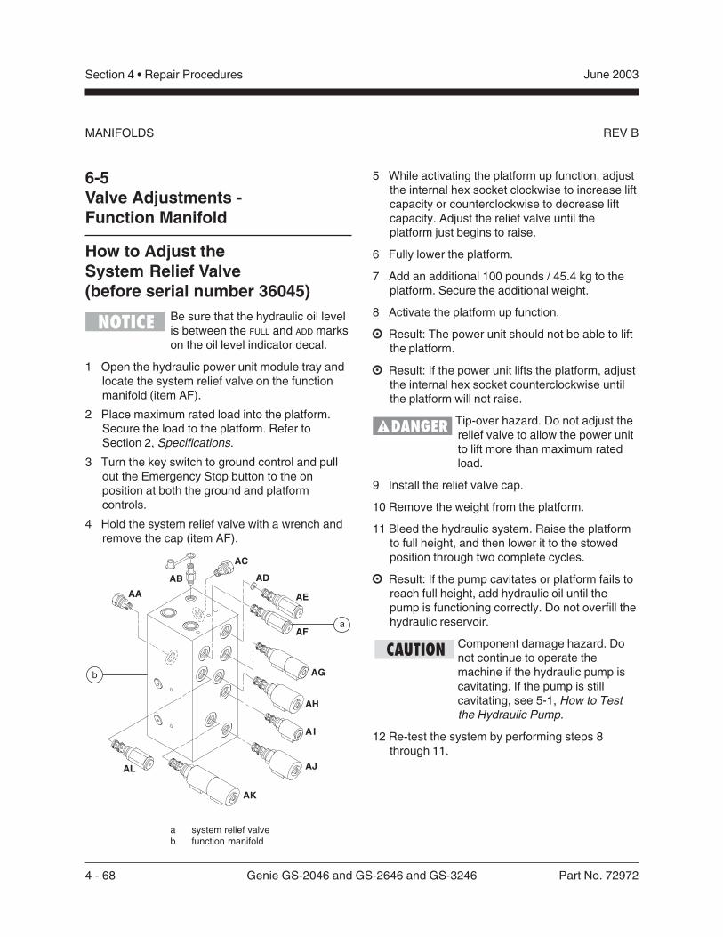
4 - 68 Genie GS-2046 and GS-2646 and GS-3246 Part No. 72972
June 2003Section 4 • Repair Procedures
REV B
6-5Valve Adjustments -Function Manifold
How to Adjust theSystem Relief Valve(before serial number 36045)
Be sure that the hydraulic oil levelis between the FULL and ADD markson the oil level indicator decal.
1 Open the hydraulic power unit module tray andlocate the system relief valve on the functionmanifold (item AF).
2 Place maximum rated load into the platform.Secure the load to the platform. Refer toSection 2, Specifications.
3 Turn the key switch to ground control and pullout the Emergency Stop button to the onposition at both the ground and platformcontrols.
4 Hold the system relief valve with a wrench andremove the cap (item AF).
a system relief valveb function manifold
MANIFOLDS
5 While activating the platform up function, adjustthe internal hex socket clockwise to increase liftcapacity or counterclockwise to decrease liftcapacity. Adjust the relief valve until theplatform just begins to raise.
6 Fully lower the platform.
7 Add an additional 100 pounds / 45.4 kg to theplatform. Secure the additional weight.
8 Activate the platform up function.
Result: The power unit should not be able to liftthe platform.
Result: If the power unit lifts the platform, adjustthe internal hex socket counterclockwise untilthe platform will not raise.
Tip-over hazard. Do not adjust therelief valve to allow the power unitto lift more than maximum ratedload.
9 Install the relief valve cap.
10 Remove the weight from the platform.
11 Bleed the hydraulic system. Raise the platformto full height, and then lower it to the stowedposition through two complete cycles.
Result: If the pump cavitates or platform fails toreach full height, add hydraulic oil until thepump is functioning correctly. Do not overfill thehydraulic reservoir.
Component damage hazard. Donot continue to operate themachine if the hydraulic pump iscavitating. If the pump is stillcavitating, see 5-1, How to Testthe Hydraulic Pump.
12 Re-test the system by performing steps 8through 11.
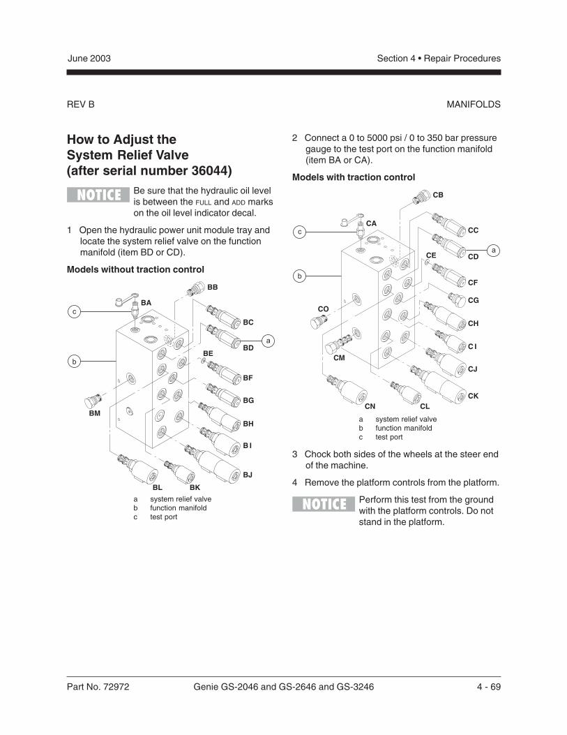
Part No. 72972 Genie GS-2046 and GS-2646 and GS-3246 4 - 69
June 2003 Section 4 • Repair Procedures
REV B
How to Adjust theSystem Relief Valve(after serial number 36044)
Be sure that the hydraulic oil levelis between the FULL and ADD markson the oil level indicator decal.
1 Open the hydraulic power unit module tray andlocate the system relief valve on the functionmanifold (item BD or CD).
Models without traction control
a system relief valveb function manifoldc test port
2 Connect a 0 to 5000 psi / 0 to 350 bar pressuregauge to the test port on the function manifold(item BA or CA).
Models with traction control
a system relief valveb function manifoldc test port
3 Chock both sides of the wheels at the steer endof the machine.
4 Remove the platform controls from the platform.
Perform this test from the groundwith the platform controls. Do notstand in the platform.
MANIFOLDS
4 - 70 Genie GS-2046 and GS-2646 and GS-3246 Part No. 72972
June 2003Section 4 • Repair Procedures
REV B
5 Turn the key switch to platform control and pullout the Emergency Stop button to the onposition at both the ground and platformcontrols.
6 Press and hold the function enable switch.
7 Move and hold the joystick controller fully ineither direction while observing the pressurereading on the pressure gauge. Note thepressure. Refer to Section 2, Specifications.
8 Turn the machine off. Hold the system reliefvalve with a wrench and remove the cap(item BD or CD).
9 Adjust the internal hex socket. Turn it clockwiseto increase the pressure or counterclockwise todecrease the pressure.
Tip-over hazard. Failure to adjustthe relief valves to specificationcould cause the machine to tipover resulting in death or seriousinjury. Do not adjust the reliefvalve pressures higher thanspecifications.
10 Install the relief valve cap.
11 Repeat steps 5 through 7 to confirm the reliefvalve pressure.
MANIFOLDS
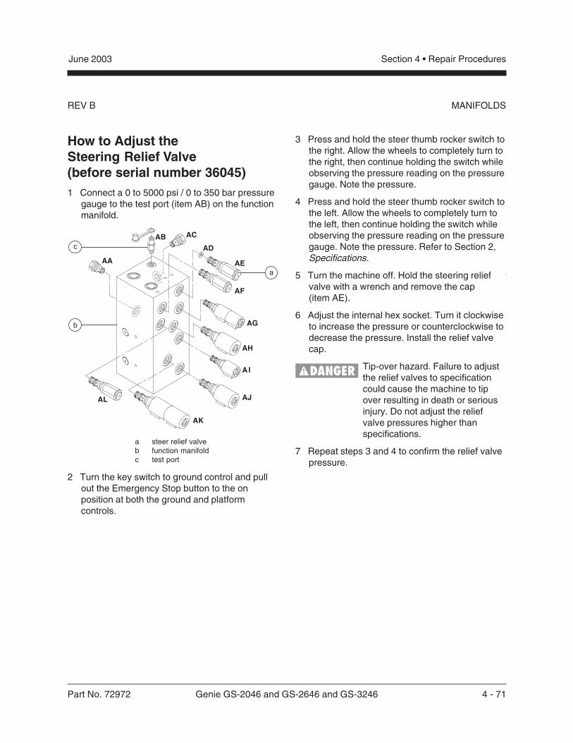
Part No. 72972 Genie GS-2046 and GS-2646 and GS-3246 4 - 71
June 2003 Section 4 • Repair Procedures
REV B
How to Adjust theSteering Relief Valve(before serial number 36045)1 Connect a 0 to 5000 psi / 0 to 350 bar pressure
gauge to the test port (item AB) on the functionmanifold.
a steer relief valveb function manifoldc test port
2 Turn the key switch to ground control and pullout the Emergency Stop button to the onposition at both the ground and platformcontrols.
3 Press and hold the steer thumb rocker switch tothe right. Allow the wheels to completely turn tothe right, then continue holding the switch whileobserving the pressure reading on the pressuregauge. Note the pressure.
4 Press and hold the steer thumb rocker switch tothe left. Allow the wheels to completely turn tothe left, then continue holding the switch whileobserving the pressure reading on the pressuregauge. Note the pressure. Refer to Section 2,Specifications.
5 Turn the machine off. Hold the steering reliefvalve with a wrench and remove the cap(item AE).
6 Adjust the internal hex socket. Turn it clockwiseto increase the pressure or counterclockwise todecrease the pressure. Install the relief valvecap.
Tip-over hazard. Failure to adjustthe relief valves to specificationcould cause the machine to tipover resulting in death or seriousinjury. Do not adjust the reliefvalve pressures higher thanspecifications.
7 Repeat steps 3 and 4 to confirm the relief valvepressure.
MANIFOLDS
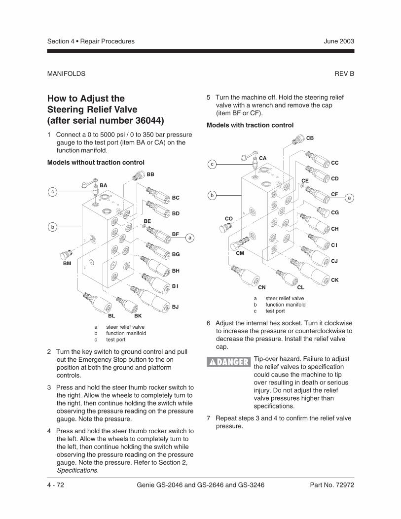
4 - 72 Genie GS-2046 and GS-2646 and GS-3246 Part No. 72972
June 2003Section 4 • Repair Procedures
REV B
How to Adjust theSteering Relief Valve(after serial number 36044)1 Connect a 0 to 5000 psi / 0 to 350 bar pressure
gauge to the test port (item BA or CA) on thefunction manifold.
Models without traction control
a steer relief valveb function manifoldc test port
2 Turn the key switch to ground control and pullout the Emergency Stop button to the onposition at both the ground and platformcontrols.
3 Press and hold the steer thumb rocker switch tothe right. Allow the wheels to completely turn tothe right, then continue holding the switch whileobserving the pressure reading on the pressuregauge. Note the pressure.
4 Press and hold the steer thumb rocker switch tothe left. Allow the wheels to completely turn tothe left, then continue holding the switch whileobserving the pressure reading on the pressuregauge. Note the pressure. Refer to Section 2,Specifications.
5 Turn the machine off. Hold the steering reliefvalve with a wrench and remove the cap(item BF or CF).
Models with traction control
a steer relief valveb function manifoldc test port
6 Adjust the internal hex socket. Turn it clockwiseto increase the pressure or counterclockwise todecrease the pressure. Install the relief valvecap.
Tip-over hazard. Failure to adjustthe relief valves to specificationcould cause the machine to tipover resulting in death or seriousinjury. Do not adjust the reliefvalve pressures higher thanspecifications.
7 Repeat steps 3 and 4 to confirm the relief valvepressure.
MANIFOLDS
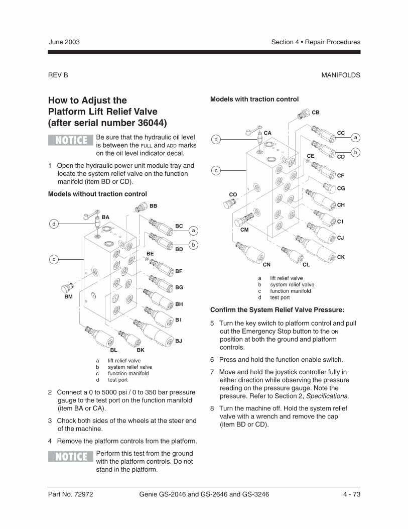
Part No. 72972 Genie GS-2046 and GS-2646 and GS-3246 4 - 73
June 2003 Section 4 • Repair Procedures
REV B
How to Adjust thePlatform Lift Relief Valve(after serial number 36044)
Be sure that the hydraulic oil levelis between the FULL and ADD markson the oil level indicator decal.
1 Open the hydraulic power unit module tray andlocate the system relief valve on the functionmanifold (item BD or CD).
Models without traction control
a lift relief valveb system relief valvec function manifoldd test port
2 Connect a 0 to 5000 psi / 0 to 350 bar pressuregauge to the test port on the function manifold(item BA or CA).
3 Chock both sides of the wheels at the steer endof the machine.
4 Remove the platform controls from the platform.
Perform this test from the groundwith the platform controls. Do notstand in the platform.
MANIFOLDS
Models with traction control
a lift relief valveb system relief valvec function manifoldd test port
Confirm the System Relief Valve Pressure:
5 Turn the key switch to platform control and pullout the Emergency Stop button to the ON
position at both the ground and platformcontrols.
6 Press and hold the function enable switch.
7 Move and hold the joystick controller fully ineither direction while observing the pressurereading on the pressure gauge. Note thepressure. Refer to Section 2, Specifications.
8 Turn the machine off. Hold the system reliefvalve with a wrench and remove the cap(item BD or CD).
4 - 74 Genie GS-2046 and GS-2646 and GS-3246 Part No. 72972
June 2003Section 4 • Repair Procedures
REV BMANIFOLDS
9 Adjust the internal hex socket. Turn it clockwiseto increase the pressure or counterclockwise todecrease the pressure.
Tip-over hazard. Failure to adjustthe relief valves to specificationcould cause the machine to tipover resulting in death or seriousinjury. Do not adjust the reliefvalve pressures higher thanspecifications.
10 Install the relief valve cap.
11 Repeat steps 5 through 7 to confirm the reliefvalve pressure.
Confirm the Lift Relief Valve Pressure:
12 Place the maximum rated load in the platform.Secure the load to the platform. Refer toSection 2, Specifications.
13 Turn the key switch to ground control and pullout the Emergency Stop button to the ON
position at both the ground and platformcontrols.
14 Hold the lift relief valve with a wrench andremove the cap (item BC or CC).
15 While activating the platform up function, adjustthe internal hex socket clockwise, just until theplatform begins to raise.
16 Fully lower the platform.
17 Add an additional 100 pounds / 45.4 kg to theplatform. Secure the additional weight.
18 Raise the platform slightly.
Result: The power unit should not be able to liftthe platform.
Result: If the power unit lifts the platform, adjustthe internal hex socket counterclockwise untilthe adjustment is correct.
19 Install the relief valve cap.
20 Remove the weight from the platform.
21 Bleed the hydraulic system by raising theplatform to full height. If the pump cavitates orthe platform fails to reach full height, addhydraulic oil until the pump is functioningcorrectly. Do not overfill the hydraulic reservoir.
Component damage hazard. Donot continue to operate themachine if the hydraulic pump iscavitating.
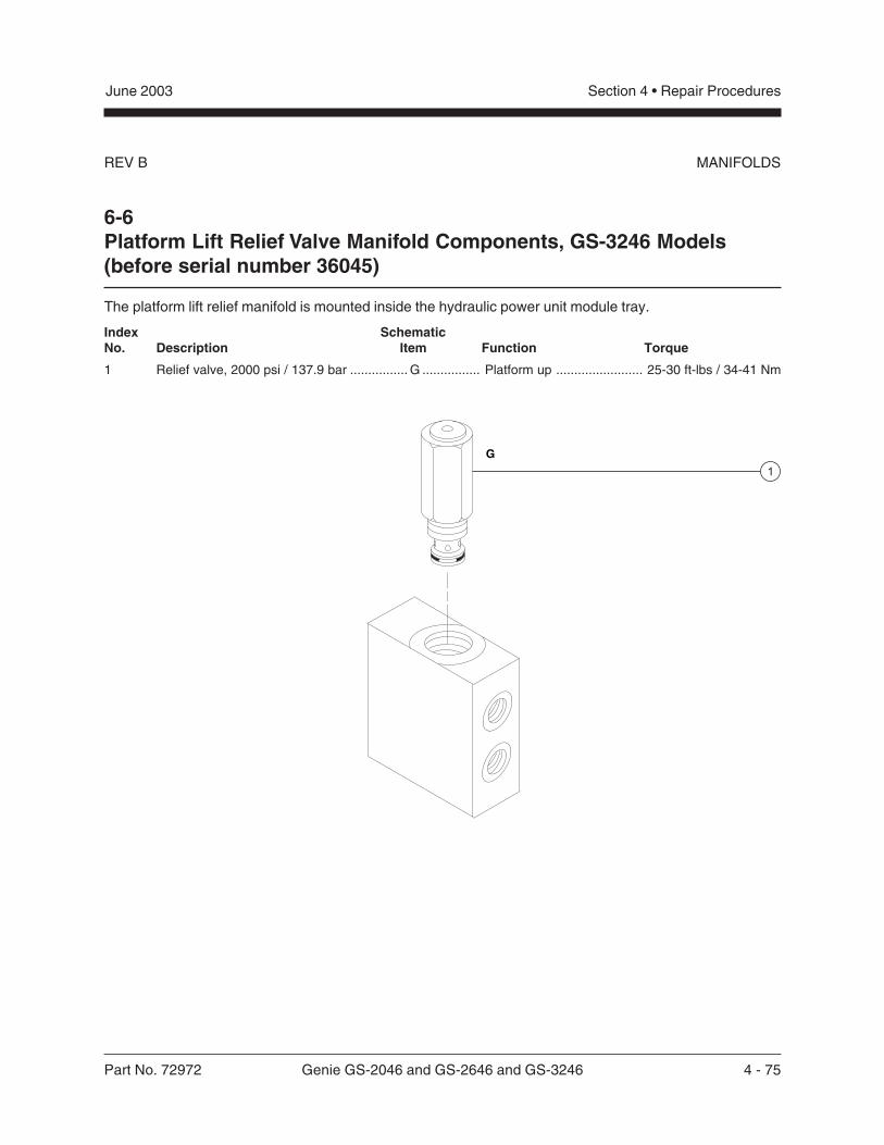
Part No. 72972 Genie GS-2046 and GS-2646 and GS-3246 4 - 75
June 2003 Section 4 • Repair Procedures
REV B
Index SchematicNo. Description Item Function Torque
1 Relief valve, 2000 psi / 137.9 bar ................ G ................ Platform up ........................ 25-30 ft-lbs / 34-41 Nm
6-6Platform Lift Relief Valve Manifold Components, GS-3246 Models(before serial number 36045)
The platform lift relief manifold is mounted inside the hydraulic power unit module tray.
MANIFOLDS
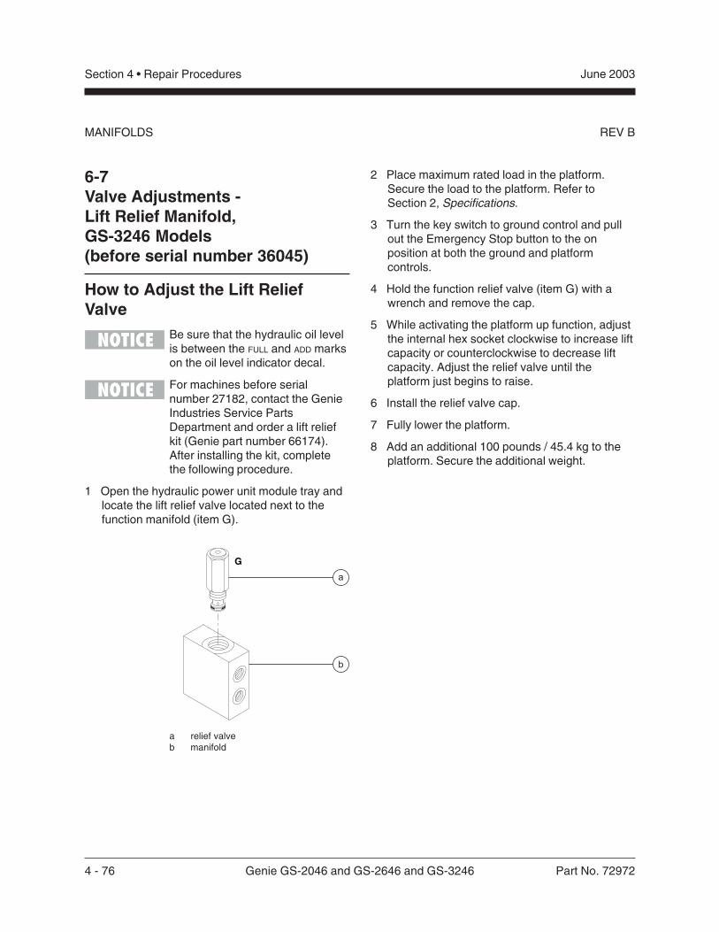
4 - 76 Genie GS-2046 and GS-2646 and GS-3246 Part No. 72972
June 2003Section 4 • Repair Procedures
REV BMANIFOLDS
6-7Valve Adjustments -Lift Relief Manifold,GS-3246 Models(before serial number 36045)
How to Adjust the Lift ReliefValve
Be sure that the hydraulic oil levelis between the FULL and ADD markson the oil level indicator decal.
For machines before serialnumber 27182, contact the GenieIndustries Service PartsDepartment and order a lift reliefkit (Genie part number 66174).After installing the kit, completethe following procedure.
1 Open the hydraulic power unit module tray andlocate the lift relief valve located next to thefunction manifold (item G).
a relief valveb manifold
2 Place maximum rated load in the platform.Secure the load to the platform. Refer toSection 2, Specifications.
3 Turn the key switch to ground control and pullout the Emergency Stop button to the onposition at both the ground and platformcontrols.
4 Hold the function relief valve (item G) with awrench and remove the cap.
5 While activating the platform up function, adjustthe internal hex socket clockwise to increase liftcapacity or counterclockwise to decrease liftcapacity. Adjust the relief valve until theplatform just begins to raise.
6 Install the relief valve cap.
7 Fully lower the platform.
8 Add an additional 100 pounds / 45.4 kg to theplatform. Secure the additional weight.
Part No. 72972 Genie GS-2046 and GS-2646 and GS-3246 4 - 77
June 2003 Section 4 • Repair Procedures
REV B MANIFOLDS
9 Activate the platform up function.
Result: The power unit should not be able to liftthe platform.
Result: If the power unit lifts the platform,remove the additional weight and repeat steps4 through 9.
Tip-over hazard. Do not adjust therelief valve to allow the power unitto lift more than maximum ratedload.
Component damage hazard. If thepump cavitates or platform fails toreach full height, add hydraulic oiluntil the pump is functioningcorrectly. Do not overfill thehydraulic reservoir.
10 Remove the weight from the platform.
11 Bleed the hydraulic system. Raise the platformto full height and then lower it to the stowedposition through two complete cycles.
Component damage hazard. Donot continue to operate themachine if the hydraulic pump iscavitating. If the pump is stillcavitating, see 5-1, How to test theHydraulic Pump.
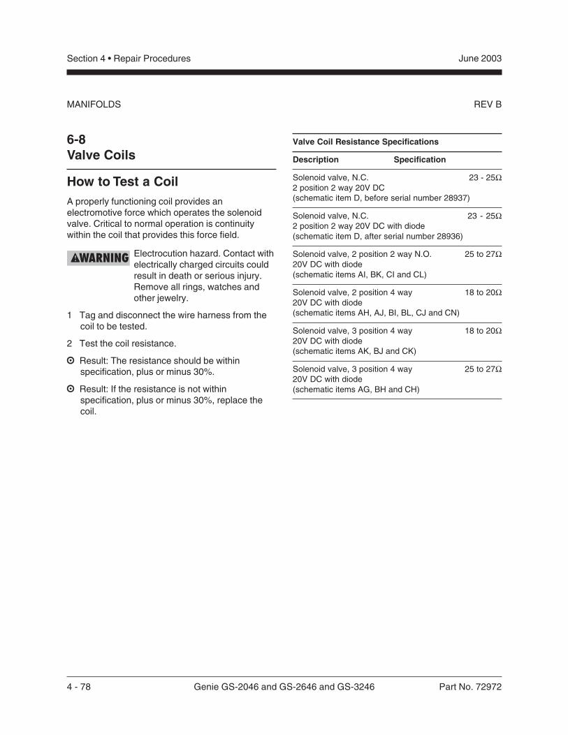
4 - 78 Genie GS-2046 and GS-2646 and GS-3246 Part No. 72972
June 2003Section 4 • Repair Procedures
REV BMANIFOLDS
6-8Valve Coils
How to Test a CoilA properly functioning coil provides anelectromotive force which operates the solenoidvalve. Critical to normal operation is continuitywithin the coil that provides this force field.
Electrocution hazard. Contact withelectrically charged circuits couldresult in death or serious injury.Remove all rings, watches andother jewelry.
1 Tag and disconnect the wire harness from thecoil to be tested.
2 Test the coil resistance.
Result: The resistance should be withinspecification, plus or minus 30%.
Result: If the resistance is not withinspecification, plus or minus 30%, replace thecoil.
Valve Coil Resistance Specifications
Description Specification
Solenoid valve, N.C. 23 - 25Ω2 position 2 way 20V DC(schematic item D, before serial number 28937)
Solenoid valve, N.C. 23 - 25Ω2 position 2 way 20V DC with diode(schematic item D, after serial number 28936)
Solenoid valve, 2 position 2 way N.O. 25 to 27Ω20V DC with diode(schematic items AI, BK, CI and CL)
Solenoid valve, 2 position 4 way 18 to 20Ω20V DC with diode(schematic items AH, AJ, BI, BL, CJ and CN)
Solenoid valve, 3 position 4 way 18 to 20Ω20V DC with diode(schematic items AK, BJ and CK)
Solenoid valve, 3 position 4 way 25 to 27Ω20V DC with diode(schematic items AG, BH and CH)
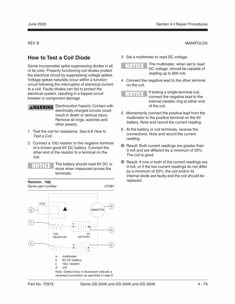
Part No. 72972 Genie GS-2046 and GS-2646 and GS-3246 4 - 79
June 2003 Section 4 • Repair Procedures
REV B MANIFOLDS
How to Test a Coil DiodeGenie incorporates spike suppressing diodes in allof its coils. Properly functioning coil diodes protectthe electrical circuit by suppressing voltage spikes.Voltage spikes naturally occur within a functioncircuit following the interruption of electrical currentto a coil. Faulty diodes can fail to protect theelectrical system, resulting in a tripped circuitbreaker or component damage.
Electrocution hazard. Contact withelectrically charged circuits couldresult in death or serious injury.Remove all rings, watches andother jewelry.
1 Test the coil for resistance. See 6-8 How toTest a Coil.
2 Connect a 10Ω resistor to the negative terminalof a known good 9V DC battery. Connect theother end of the resistor to a terminal on thecoil.
The battery should read 9V DC ormore when measured across theterminals.
Resistor, 10ΩΩΩΩΩGenie part number 27287
a multimeterb 9V DC batteryc 10Ω resistord coil
3 Set a multimeter to read DC voltage.
The multimeter, when set to readDC voltage, should be capable ofreading up to 800 mA.
4 Connect the negative lead to the other terminalon the coil.
If testing a single-terminal coil,connect the negative lead to theinternal metallic ring at either endof the coil.
5 Momentarily connect the positive lead from themultimeter to the positive terminal on the 9Vbattery. Note and record the current reading.
6 At the battery or coil terminals, reverse theconnections. Note and record the currentreading.
Result: Both current readings are greater than0 mA and are different by a minimum of 20%.The coil is good.
Result: If one or both of the current readings are0 mA, or if the two current readings do not differby a minimum of 20%, the coil and/or itsinternal diode are faulty and the coil should bereplaced.
9VBATTERY
10
RESISTOR
�
AMMETER
COIL
+
-
+
-
d
b
b
a
c
c
Note: Dotted lines in illustration indicate areversed connection as specified in step 6
4 - 80 Genie GS-2046 and GS-2646 and GS-3246 Part No. 72972
June 2003Section 4 • Repair Procedures
REV A
7-1Hydraulic Tank
The primary functions of the hydraulic tank are tocool, clean and deaerate the hydraulic fluid duringoperation. It utilizes internal suction strainers forthe pump supply lines and has an external returnline filter.
How to Remove theHydraulic Tank
Component damage hazard. Thework area and surfaces where thisprocedure will be performed mustbe clean and free of debris thatcould get into the hydraulicsystem.
When removing a hose assemblyor fitting, the O-ring on the fittingand/or hose end must be replacedand then torqued to specificationduring installation. Refer toSection Two, Hydraulic Hose andFitting Torque Specifications.
Perform this procedure with theplatform in the stowed position.
1 Disconnect the battery pack from the machine.
Electrocution hazard. Contact withelectrically charged circuits couldresult in death or serious injury.Remove all rings, watches andother jewelry.
2 Open the power unit module tray.
3 Remove the drain plug from the hydraulic tankand allow all of the oil from the tank to drain intoa suitable container. Refer to Section 2,Specifications.
Bodily injury hazard. Sprayinghydraulic oil can penetrate andburn skin. Loosen hydraulicconnections very slowly to allowthe oil pressure to dissipategradually. Do not allow oil to squirtor spray.
4 Tag, disconnect and plug the hydraulic tankreturn hose at the top of the hydraulic tank.
5 Remove the motor controller mounting bracketretaining fasteners and move the motorcontroller to the side.
6 Remove the return filter mounting bracketfasteners from the manifold. Push the filter andaccumulator out of the way.
7 Tag, disconnect and plug the hydraulic pumpinlet hose at the side of the hydraulic tank.
8 Remove the hydraulic tank retaining fastenersand remove the hydraulic tank from themachine.
Hydraulic Tank
Part No. 72972 Genie GS-2046 and GS-2646 and GS-3246 4 - 81
June 2003 Section 4 • Repair Procedures
REV ASteer Axle Components
8-1Yoke and Drive Motor
How to Remove the Yokeand Drive Motor
When removing a hose assemblyor fitting, the O-ring on the fittingand/or hose end must be replacedand then torqued to specificationduring installation. Refer toSection Two, Hydraulic Hose andFitting Torque Specifications.
1 Block the non-steer wheels.
2 Center a lifting jack under the drive chassis atthe steer end of the machine.
3 Remove the cotter pin from the wheel castlenut.
Always replace the cotter pin witha new one when removing thecastle nut.
4 Loosen the wheel castle nut. Do not remove it.
5 Raise the machine approximately14 inches / 36 cm. Place blocks under thechassis for support.
Crushing hazard. The chassis willfall if it is not properly supported.
6 Remove the wheel castle nut. Remove thewheel.
7 Tag, disconnect and cap the hydraulic hoses onthe drive motor.
Bodily injury hazard. Sprayinghydraulic oil can penetrate andburn skin. Loosen hydraulicconnections very slowly toallow the oil pressure todissipate gradually. Do notallow oil to squirt or spray.
Component damage hazard.Hoses can be damaged if they arekinked or pinched.
8 Support and secure the yoke assembly to anappropriate lifting device.
9 Remove the retaining fastener from the steerlink at the yoke assembly.
Note the quantity and location ofthe spacers when disconnectingthe steer link from the yokeassembly.
10 Remove the retaining fastener from the top ofthe yoke pivot shaft.
11 Lower the yoke assembly out of the chassis.
Bodily injury hazard. The yoke/motor assembly may fall if notproperly supported when it isremoved from the chassis.
During re-assembly, be sure thatthe spacers are installed onto thesteer link.
4 - 82 Genie GS-2046 and GS-2646 and GS-3246 Part No. 72972
June 2003Section 4 • Repair Procedures
REV ASTEER AXLE COMPONENTS
How to Remove a Drive Motor1 Block the non-steer wheels.
2 Center a lifting jack under the drive chassis atthe steer end.
3 Remove the cotter pin on the wheel lug nut ofthe motor to be removed.
Always replace the cotter pin witha new one when removing thecastle nut.
4 Loosen the wheel castle nut. Do not remove it.
5 Raise the machine approximately2 inches / 5 cm. Place blocks under the chassisfor support.
Crushing hazard. The chassis willfall if it is not properly supported.
6 Remove the wheel castle nut. Remove thewheel.
7 Tag, disconnect and plug the hydraulic hoseson the drive motor. Cap the fittings.
Bodily injury hazard. Sprayinghydraulic oil can penetrate andburn skin. Loosen hydraulicconnections very slowly toallow the oil pressure todissipate gradually. Do notallow oil to squirt or spray.
Component damage hazard.Hoses can be damaged if they arekinked or pinched.
8 Remove the drive motor mounting fasteners.Remove the drive motor.
Torque specifications
Drive motor mounting fasteners, dry 75 ft-lbs101.7 Nm
Drive motor mounting fasteners, lubricated 56 ft-lbs76.3 Nm
Part No. 72972 Genie GS-2046 and GS-2646 and GS-3246 4 - 83
June 2003 Section 4 • Repair Procedures
REV A STEER AXLE COMPONENTS
8-2Steer Cylinder
How to Remove theSteer Cylinder
When removing a hose assemblyor fitting, the O-ring on the fittingand/or hose end must be replacedand then torqued to specificationduring installation. Refer toSection Two, Hydraulic Hose andFitting Torque Specifications.
1 Block the non-steer wheels.
2 Tag, disconnect and plug the hydraulic hosesfrom the steering cylinder. Cap the fittings onthe cylinder.
Bodily injury hazard. Sprayinghydraulic oil can penetrate andburn skin. Loosen hydraulicconnections very slowly to allowthe oil pressure to dissipategradually. Do not allow oil tosquirt or spray.
Component damage hazard.Hoses can be damaged if they arekinked or pinched.
3 Remove the pin retaining fasteners from thebarrel-end pivot pin. Remove the pivot pin.
Note the quantity and location ofthe spacers when removing thebarrel-end pivot pin.
4 Remove the pin retaining fasteners from therod-end pivot pin. Remove the pin.
Note the quantity and location ofthe spacers when removing therod-end pivot pin.
5 Remove the steering cylinder from the machine.
4 - 84 Genie GS-2046 and GS-2646 and GS-3246 Part No. 72972
June 2003Section 4 • Repair Procedures
REV ASTEER AXLE COMPONENTS
8-3Steer Bellcrank
How to Remove theSteer Bellcrank
Perform this procedure with themachine on a flat, level surface.
1 Remove the steering cylinder. See 7-2, How toRemove the Steering Cylinder.
2 From serial number 17408 to 43000: Removethe retaining fastener from the center pivot pinof the bellcrank.After serial number 43000: Remove theretaining fastener from the center pivot pin ofthe bellcrank. Remove the pin.
Note the quantity and the locationof the spacers on the bellcrank.
3 Remove the retaining fasteners from the steerlinks at each end of the bellcrank.
Note the quantity and the locationof the spacers in between thebellcrank and the steer links.
4 Raise the machine approximately14 inches / 36 cm. Place blocks under thechassis for support.
Crushing hazard. The chassis willfall if it is not properly supported.
4 Turn the yokes to the side so the bellcrank canbe removed.
5 Remove the bellcrank from the machine.
Note the quantity and the locationof the spacers in between thebellcrank and the steer links.
Part No. 72972 Genie GS-2046 and GS-2646 and GS-3246 4 - 85
June 2003 Section 4 • Repair Procedures
REV ANon-Steer Axle Components
9-1Drive Brake
How to Remove a Drive BrakeWhen removing a hose assemblyor fitting, the O-ring on the fittingand/or hose end must be replacedand then torqued to specificationduring installation. Refer toSection Two, Hydraulic Hose andFitting Torque Specifications.
1 Support and secure the entry ladder to anappropriate lifting device.
2 Remove the entry ladder mounting fasteners.Remove the entry ladder from the machine.
Crushing hazard. The entry laddermay become unbalanced and fallif it is not properly supported andsecured to the lifting device.
3 Block the steer wheels.
4 Center a lifting jack under the drive chassis atthe non-steer end.
5 Remove the cotter pin from the wheel castlenut.
Always replace the cotter pin witha new one when removing thecastle nut.
6 Loosen the wheel castle nut. Do not remove it.
7 Raise the machine approximately2 inches / 5 cm. Place blocks under the chassisfor support.
Crushing hazard. The chassis willfall if it is not properly supported.
8 Remove the wheel castle nut. Remove thewheel.
9 Disconnect and plug the hydraulic hose fromthe brake. Cap the fittings on the brake.
Bodily injury hazard. Sprayinghydraulic oil can penetrate andburn skin. Loosen hydraulicconnections very slowly toallow the oil pressure todissipate gradually. Do notallow oil to squirt or spray.
10 Place a lifting jack under the brake for support.
11 Remove the fasteners that attach the brake tothe drive chassis. Remove the brake.
Crushing hazard. The brake willfall if it is not properly supportedwhen the mounting fasteners areremoved.
Torque specifications
Brake mounting fasteners, dry 75 ft-lbs101.7 Nm
Brake mounting fasteners, lubricated 56 ft-lbs76.3 Nm
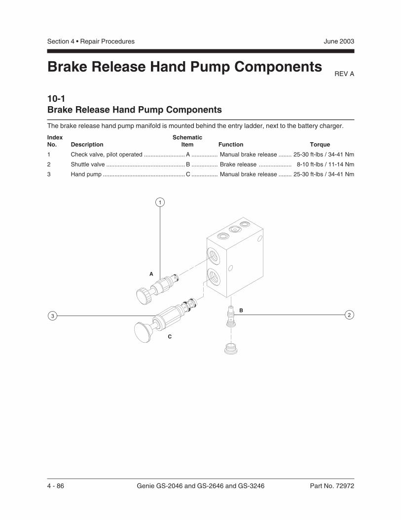
4 - 86 Genie GS-2046 and GS-2646 and GS-3246 Part No. 72972
June 2003Section 4 • Repair Procedures
REV A
Index SchematicNo. Description Item Function Torque
1 Check valve, pilot operated ......................... A ................ Manual brake release ........ 25-30 ft-lbs / 34-41 Nm
2 Shuttle valve ................................................ B ................ Brake release .................... 8-10 ft-lbs / 11-14 Nm
3 Hand pump .................................................. C ................ Manual brake release ........ 25-30 ft-lbs / 34-41 Nm
10-1Brake Release Hand Pump Components
The brake release hand pump manifold is mounted behind the entry ladder, next to the battery charger.
Brake Release Hand Pump Components
Part No. 72972 Genie GS-2046 and GS-2646 and GS-3246 5 - 1
June 2003 Section 5 • Troubleshooting Flow Charts
Before Troubleshooting:
Read, understand and obey the safety rules andoperating instructions printed in theGenie GS-2032 and GS-2632 and GS-2046 andGS-2646 and GS-3246 Operator’s Manual.
Be sure that all necessary tools and testequipment are available and ready for use.
Read each appropriate flow chart thoroughly.Attempting shortcuts may produce hazardousconditions.
Be aware of the following hazards and followgenerally accepted safe workshop practices.
Crushing hazard. When testingor replacing any hydrauliccomponent, always supportthe structure and secure itfrom movement.
Electrocution hazard. Contactwith electrically charged circuitscould result in death or seriousinjury. Remove all rings, watchesand other jewelry.
Bodily injury hazard. Sprayinghydraulic oil can penetrate andburn skin. Loosen hydraulicconnections very slowly to allowthe oil pressure to dissipategradually. Do not allow oil tosquirt or spray.
Two persons will be required tosafely perform sometroubleshooting procedures.
Troubleshooting Flow Charts
Observe and Obey:
Troubleshooting and repair procedures shall becompleted by a person trained and qualified onthe repair of this machine.
Immediately tag and remove from service adamaged or malfunctioning machine.
Repair any machine damage or malfunctionbefore operating the machine.
Unless otherwise specified, perform eachrepair procedure with the machine in thefollowing configuration:
· Machine parked on a firm, level surface
· Platform in the stowed position
· Key switch in the off position with the keyremoved
· Wheels chocked
· All external AC power supply disconnectedfrom the machine
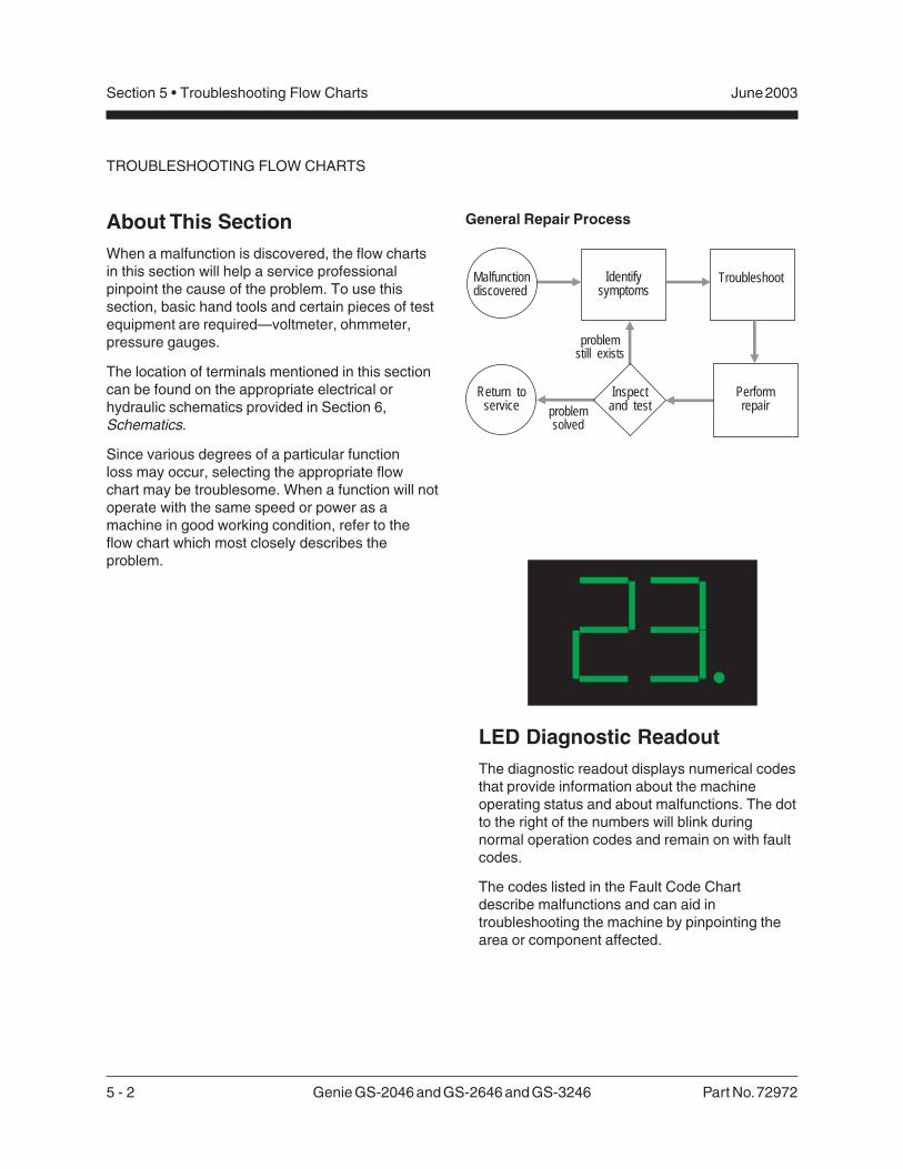
5 - 2 Genie GS-2046 and GS-2646 and GS-3246 Part No. 72972
June 2003Section 5 • Troubleshooting Flow Charts
General Repair Process
TROUBLESHOOTING FLOW CHARTS
About This SectionWhen a malfunction is discovered, the flow chartsin this section will help a service professionalpinpoint the cause of the problem. To use thissection, basic hand tools and certain pieces of testequipment are required—voltmeter, ohmmeter,pressure gauges.
The location of terminals mentioned in this sectioncan be found on the appropriate electrical orhydraulic schematics provided in Section 6,Schematics.
Since various degrees of a particular functionloss may occur, selecting the appropriate flowchart may be troublesome. When a function will notoperate with the same speed or power as amachine in good working condition, refer to theflow chart which most closely describes theproblem.
Malfunctiondiscovered
Identifysymptoms
Troubleshoot
Performrepair
Return toservice problem
solved
problemstill exists
Inspectand test
LED Diagnostic ReadoutThe diagnostic readout displays numerical codesthat provide information about the machineoperating status and about malfunctions. The dotto the right of the numbers will blink duringnormal operation codes and remain on with faultcodes.
The codes listed in the Fault Code Chartdescribe malfunctions and can aid introubleshooting the machine by pinpointing thearea or component affected.
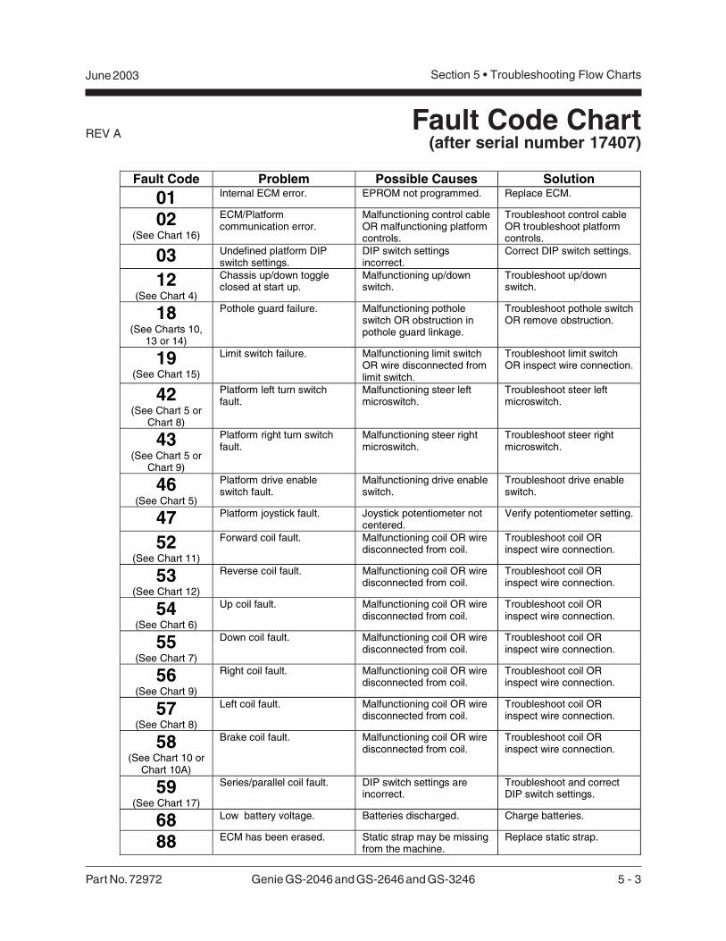
Part No. 72972 Genie GS-2046 and GS-2646 and GS-3246 5 - 3
June 2003 Section 5 • Troubleshooting Flow Charts
REV AFault Code Chart
(after serial number 17407)
Fault Code Problem Possible Causes Solution
01 Internal ECM error. EPROM not programmed. Replace ECM.
02(See Chart 16)
ECM/Platformcommunication error.
Malfunctioning control cableOR malfunctioning platformcontrols.
Troubleshoot control cableOR troubleshoot platformcontrols.
03 Undefined platform DIPswitch settings.
DIP switch settingsincorrect.
Correct DIP switch settings.
12(See Chart 4)
Chassis up/down toggleclosed at start up.
Malfunctioning up/downswitch.
Troubleshoot up/downswitch.
18(See Charts 10,
13 or 14)
Pothole guard failure. Malfunctioning potholeswitch OR obstruction inpothole guard linkage.
Troubleshoot pothole switchOR remove obstruction.
19(See Chart 15)
Limit switch failure. Malfunctioning limit switchOR wire disconnected fromlimit switch.
Troubleshoot limit switchOR inspect wire connection.
42(See Chart 5 or
Chart 8)
Platform left turn switchfault.
Malfunctioning steer leftmicroswitch.
Troubleshoot steer leftmicroswitch.
43(See Chart 5 or
Chart 9)
Platform right turn switchfault.
Malfunctioning steer rightmicroswitch.
Troubleshoot steer rightmicroswitch.
46(See Chart 5)
Platform drive enableswitch fault.
Malfunctioning drive enableswitch.
Troubleshoot drive enableswitch.
47 Platform joystick fault. Joystick potentiometer notcentered.
Verify potentiometer setting.
52(See Chart 11)
Forward coil fault. Malfunctioning coil OR wiredisconnected from coil.
Troubleshoot coil ORinspect wire connection.
53(See Chart 12)
Reverse coil fault. Malfunctioning coil OR wiredisconnected from coil.
Troubleshoot coil ORinspect wire connection.
54(See Chart 6)
Up coil fault. Malfunctioning coil OR wiredisconnected from coil.
Troubleshoot coil ORinspect wire connection.
55(See Chart 7)
Down coil fault. Malfunctioning coil OR wiredisconnected from coil.
Troubleshoot coil ORinspect wire connection.
56(See Chart 9)
Right coil fault. Malfunctioning coil OR wiredisconnected from coil.
Troubleshoot coil ORinspect wire connection.
57(See Chart 8)
Left coil fault. Malfunctioning coil OR wiredisconnected from coil.
Troubleshoot coil ORinspect wire connection.
58(See Chart 10 or
Chart 10A)
Brake coil fault. Malfunctioning coil OR wiredisconnected from coil.
Troubleshoot coil ORinspect wire connection.
59(See Chart 17)
Series/parallel coil fault. DIP switch settings areincorrect.
Troubleshoot and correctDIP switch settings.
68 Low battery voltage. Batteries discharged. Charge batteries.
88 ECM has been erased. Static strap may be missingfrom the machine.
Replace static strap.
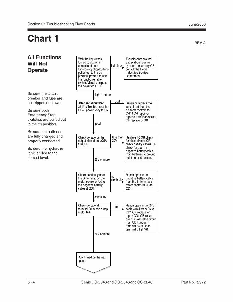
5 - 4 Genie GS-2046 and GS-2646 and GS-3246 Part No. 72972
REV A
Section 5 • Troubleshooting Flow Charts June 2003
All FunctionsWill NotOperate
Be sure the circuitbreaker and fuse arenot tripped or blown.
Be sure bothEmergency Stopswitches are pulled outto the ON position.
Be sure the batteriesare fully charged andproperly connected.
Be sure the hydraulictank is filled to thecorrect level.
Chart 1
Replace F6 OR checkfor short circuits ORcheck battery cables ORcheck for open innegative battery cablefrom batteries to groundpoint on module tray.20V or more
Continued on the nextpage.
Check voltage on theoutput side of the 275Afuse F6.
less than20V
Check voltage atterminal D1 at the pumpmotor M6.
Repair open in the 24Vcable circuit from F6 toQD1 OR replace orrepair QD1 OR repairopen in 24V cable circuitfrom QD1 throughterminal B+ at U6 toterminal D1 at M6.
20V or more
Check continuity fromthe B- terminal on themotor controller U6 tothe negative batterycable at QD1.
nocontinuity
continuity
Repair open in thenegative battery cablefrom the B- terminal atmotor controller U6 toQD1.
With the key switchturned to platformcontrol and bothEmergency Stop buttonspulled out to the ONposition, press and holdthe function enableswitch. Visually inspectthe power-on LED.
light is on
light is not on
Troubleshoot groundand platform controlsystems separately ORconsult the GenieIndustries ServiceDepartment.
0V
After serial number25141: Troubleshoot theCR48 power relay to U5
good
bad Repair or replace thewire circuit from theplatform controls toCR48 OR repair orreplace the CR48 socketOR replace CR48.
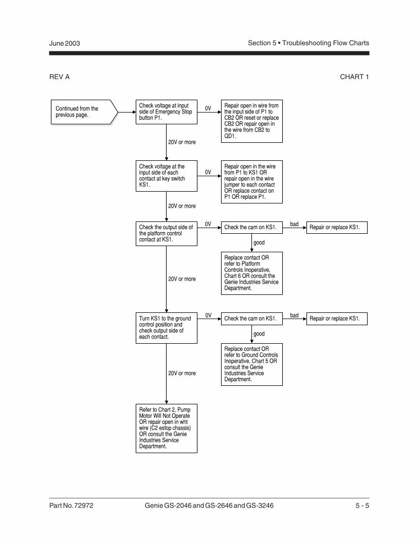
Part No. 72972 Genie GS-2046 and GS-2646 and GS-3246 5 - 5
June 2003 Section 5 • Troubleshooting Flow Charts
REV A CHART 1
Continued from theprevious page.
Check voltage at theinput side of eachcontact at key switchKS1.
Repair open in the wirefrom P1 to KS1 ORrepair open in the wirejumper to each contactOR replace contact onP1 OR replace P1.
20V or more
Check the output side ofthe platform controlcontact at KS1.
Check the cam on KS1. bad Repair or replace KS1.
good
Replace contact ORrefer to Ground ControlsInoperative, Chart 5 ORconsult the GenieIndustries ServiceDepartment.
20V or more
0V
0V
Turn KS1 to the groundcontrol position andcheck output side ofeach contact.
Replace contact ORrefer to PlatformControls Inoperative,Chart 6 OR consult theGenie Industries ServiceDepartment.
20V or more
Refer to Chart 2, PumpMotor Will Not OperateOR repair open in whtwire (C2 estop chassis)OR consult the GenieIndustries ServiceDepartment.
0V Check the cam on KS1. bad Repair or replace KS1.
good
Check voltage at inputside of Emergency Stopbutton P1.
0V
20V or more
Repair open in wire fromthe input side of P1 toCB2 OR reset or replaceCB2 OR repair open inthe wire from CB2 toQD1.
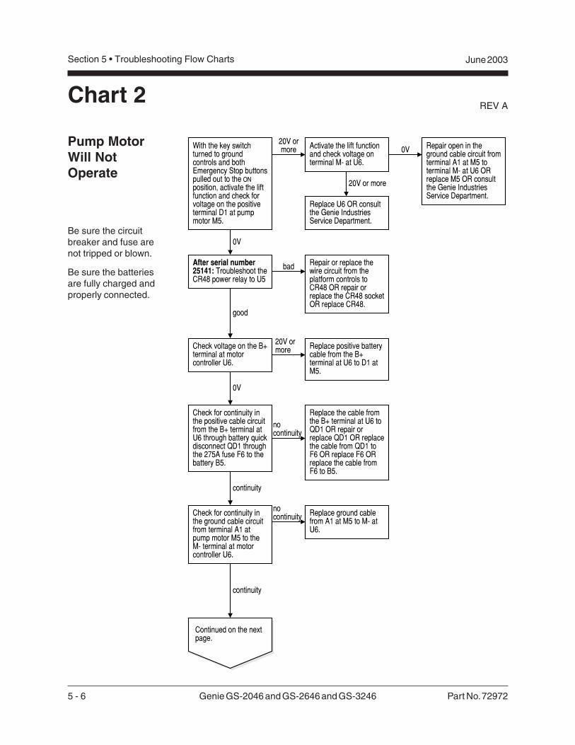
5 - 6 Genie GS-2046 and GS-2646 and GS-3246 Part No. 72972
REV A
Section 5 • Troubleshooting Flow Charts June 2003
Chart 2
Pump MotorWill NotOperate
Be sure the circuitbreaker and fuse arenot tripped or blown.
Be sure the batteriesare fully charged andproperly connected.
With the key switchturned to groundcontrols and bothEmergency Stop buttonspulled out to the ONposition, activate the liftfunction and check forvoltage on the positiveterminal D1 at pumpmotor M5.
20V ormore
Check for continuity inthe ground cable circuitfrom terminal A1 atpump motor M5 to theM- terminal at motorcontroller U6.
nocontinuity
continuity
Replace ground cablefrom A1 at M5 to M- atU6.
0V
Continued on the nextpage.
Check voltage on the B+terminal at motorcontroller U6.
20V ormore Replace positive battery
cable from the B+terminal at U6 to D1 atM5.
0V
Replace the cable fromthe B+ terminal at U6 toQD1 OR repair orreplace QD1 OR replacethe cable from QD1 toF6 OR replace F6 ORreplace the cable fromF6 to B5.
Check for continuity inthe positive cable circuitfrom the B+ terminal atU6 through battery quickdisconnect QD1 throughthe 275A fuse F6 to thebattery B5.
continuity
nocontinuity
0V
20V or more
Activate the lift functionand check voltage onterminal M- at U6.
Repair open in theground cable circuit fromterminal A1 at M5 toterminal M- at U6 ORreplace M5 OR consultthe Genie IndustriesService Department.
Replace U6 OR consultthe Genie IndustriesService Department.
After serial number25141: Troubleshoot theCR48 power relay to U5
good
bad Repair or replace thewire circuit from theplatform controls toCR48 OR repair orreplace the CR48 socketOR replace CR48.
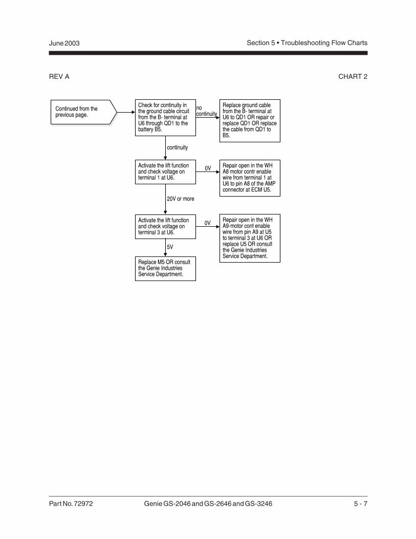
Part No. 72972 Genie GS-2046 and GS-2646 and GS-3246 5 - 7
June 2003 Section 5 • Troubleshooting Flow Charts
REV A CHART 2
Continued from theprevious page.
Activate the lift functionand check voltage onterminal 1 at U6.
20V or more
Replace ground cablefrom the B- terminal atU6 to QD1 OR repair orreplace QD1 OR replacethe cable from QD1 toB5.
Check for continuity inthe ground cable circuitfrom the B- terminal atU6 through QD1 to thebattery B5.
nocontinuity
Repair open in the WHA8 motor contr enablewire from terminal 1 atU6 to pin A8 of the AMPconnector at ECM U5.
Activate the lift functionand check voltage onterminal 3 at U6.
Repair open in the WHA9-motor cont enablewire from pin A9 at U5to terminal 3 at U6 ORreplace U5 OR consultthe Genie IndustriesService Department.
0V
5V
Replace M5 OR consultthe Genie IndustriesService Department.
0V
continuity
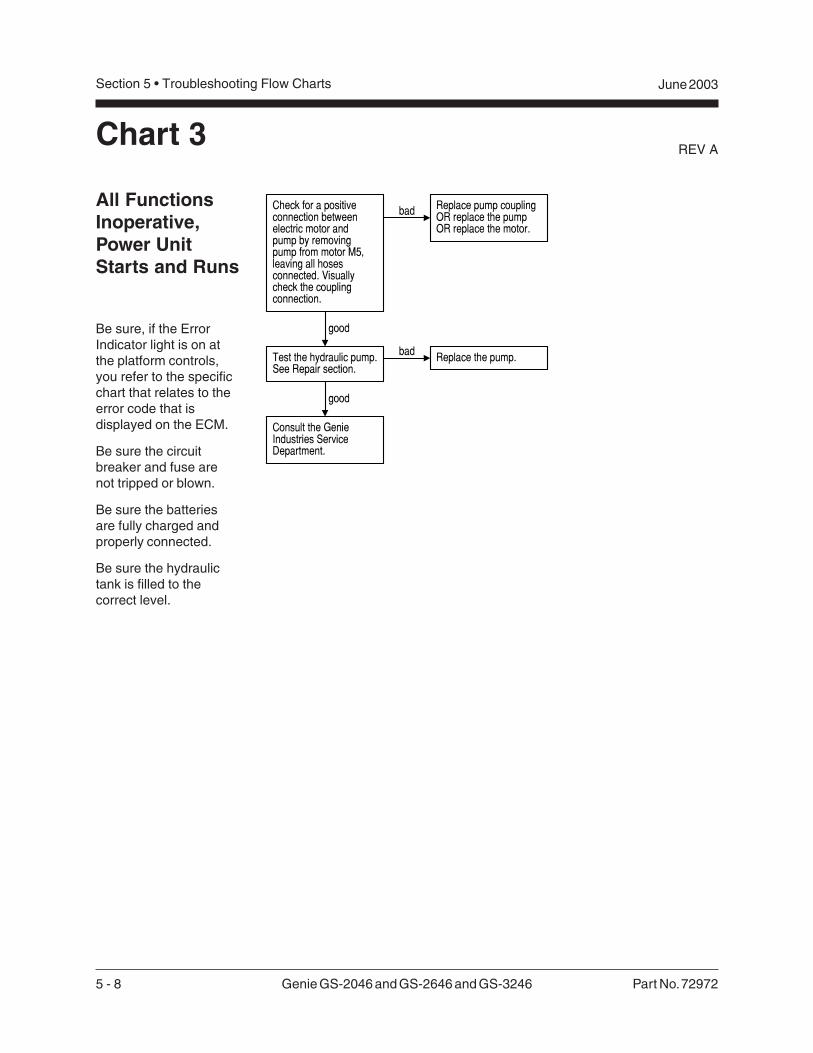
5 - 8 Genie GS-2046 and GS-2646 and GS-3246 Part No. 72972
REV A
Section 5 • Troubleshooting Flow Charts June 2003
Chart 3
All FunctionsInoperative,Power UnitStarts and Runs
Be sure, if the ErrorIndicator light is on atthe platform controls,you refer to the specificchart that relates to theerror code that isdisplayed on the ECM.
Be sure the circuitbreaker and fuse arenot tripped or blown.
Be sure the batteriesare fully charged andproperly connected.
Be sure the hydraulictank is filled to thecorrect level.
Check for a positiveconnection betweenelectric motor andpump by removingpump from motor M5,leaving all hosesconnected. Visuallycheck the couplingconnection.
bad Replace pump couplingOR replace the pumpOR replace the motor.
good
Test the hydraulic pump.See Repair section.
Consult the GenieIndustries ServiceDepartment.
bad Replace the pump.
good
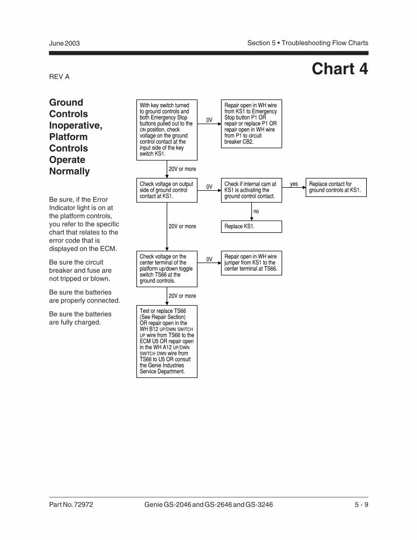
Part No. 72972 Genie GS-2046 and GS-2646 and GS-3246 5 - 9
June 2003 Section 5 • Troubleshooting Flow Charts
REV A
GroundControlsInoperative,PlatformControlsOperateNormally
Be sure, if the ErrorIndicator light is on atthe platform controls,you refer to the specificchart that relates to theerror code that isdisplayed on the ECM.
Be sure the circuitbreaker and fuse arenot tripped or blown.
Be sure the batteriesare properly connected.
Be sure the batteriesare fully charged.
Chart 4
With key switch turnedto ground controls andboth Emergency Stopbuttons pulled out to theON position, checkvoltage on the groundcontrol contact at theinput side of the keyswitch KS1.
0V
Repair open in WH wirefrom KS1 to EmergencyStop button P1 ORrepair or replace P1 ORrepair open in WH wirefrom P1 to circuitbreaker CB2.
20V or more
Check voltage on outputside of ground controlcontact at KS1.
Check if internal cam atKS1 is activating theground control contact.
yes Replace contact forground controls at KS1.
no
Replace KS1.20V or more
Repair open in WH wirejumper from KS1 to thecenter terminal at TS66.
Check voltage on thecenter terminal of theplatform up/down toggleswitch TS66 at theground controls.
0V
20V or more
Test or replace TS66(See Repair Section)OR repair open in theWH B12 UP/DWN SWITCHUP wire from TS66 to theECM U5 OR repair openin the WH A12 UP/DWNSWITCH DWN wire fromTS66 to U5 OR consultthe Genie IndustriesService Department.
0V
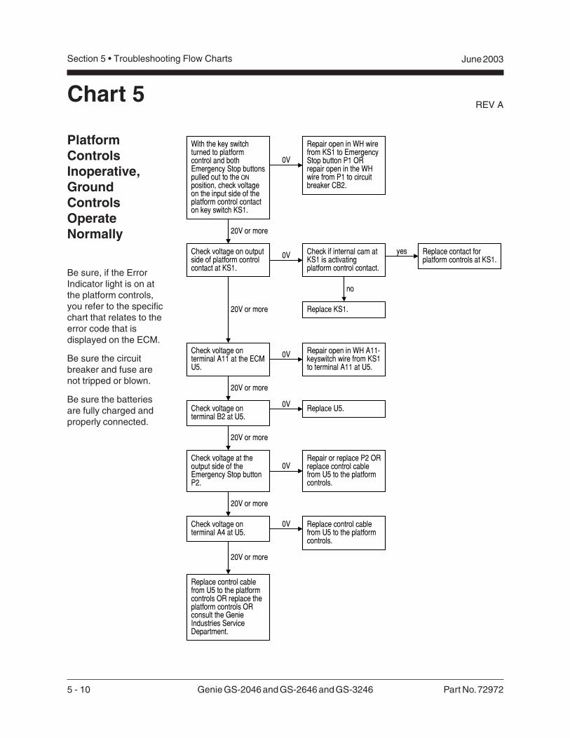
5 - 10 Genie GS-2046 and GS-2646 and GS-3246 Part No. 72972
REV A
Section 5 • Troubleshooting Flow Charts June 2003
Chart 5
PlatformControlsInoperative,GroundControlsOperateNormally
Be sure, if the ErrorIndicator light is on atthe platform controls,you refer to the specificchart that relates to theerror code that isdisplayed on the ECM.
Be sure the circuitbreaker and fuse arenot tripped or blown.
Be sure the batteriesare fully charged andproperly connected.
With the key switchturned to platformcontrol and bothEmergency Stop buttonspulled out to the ONposition, check voltageon the input side of theplatform control contacton key switch KS1.
0V
Repair open in WH wirefrom KS1 to EmergencyStop button P1 ORrepair open in the WHwire from P1 to circuitbreaker CB2.
20V or more
Check voltage on outputside of platform controlcontact at KS1.
0V Check if internal cam atKS1 is activatingplatform control contact.
yes Replace contact forplatform controls at KS1.
no
Replace KS1.20V or more
Repair or replace P2 ORreplace control cablefrom U5 to the platformcontrols.
Check voltage at theoutput side of theEmergency Stop buttonP2.
0V
20V or more
Check voltage onterminal B2 at U5.
0V Replace U5.
Check voltage onterminal A11 at the ECMU5.
0V Repair open in WH A11-keyswitch wire from KS1to terminal A11 at U5.
20V or more
20V or more
20V or more
Check voltage onterminal A4 at U5.
0V Replace control cablefrom U5 to the platformcontrols.
Replace control cablefrom U5 to the platformcontrols OR replace theplatform controls ORconsult the GenieIndustries ServiceDepartment.
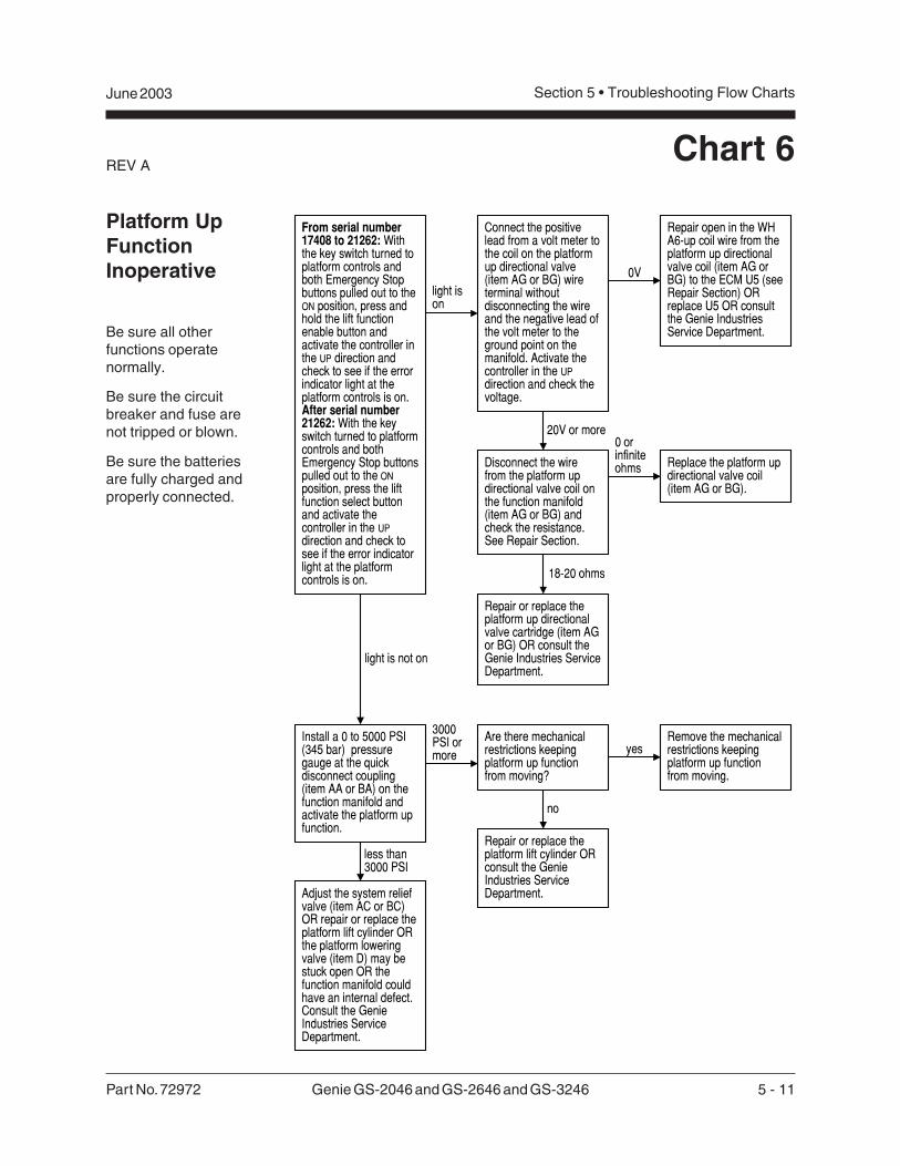
Part No. 72972 Genie GS-2046 and GS-2646 and GS-3246 5 - 11
June 2003 Section 5 • Troubleshooting Flow Charts
REV A
Platform UpFunctionInoperative
Be sure all otherfunctions operatenormally.
Be sure the circuitbreaker and fuse arenot tripped or blown.
Be sure the batteriesare fully charged andproperly connected.
Chart 6
From serial number17408 to 21262: Withthe key switch turned toplatform controls andboth Emergency Stopbuttons pulled out to theON position, press andhold the lift functionenable button andactivate the controller inthe UP direction andcheck to see if the errorindicator light at theplatform controls is on.After serial number21262: With the keyswitch turned to platformcontrols and bothEmergency Stop buttonspulled out to the ONposition, press the liftfunction select buttonand activate thecontroller in the UPdirection and check tosee if the error indicatorlight at the platformcontrols is on.
light ison
light is not on
Connect the positivelead from a volt meter tothe coil on the platformup directional valve(item AG or BG) wireterminal withoutdisconnecting the wireand the negative lead ofthe volt meter to theground point on themanifold. Activate thecontroller in the UPdirection and check thevoltage.
Disconnect the wirefrom the platform updirectional valve coil onthe function manifold(item AG or BG) andcheck the resistance.See Repair Section.
0V
Repair open in the WHA6-up coil wire from theplatform up directionalvalve coil (item AG orBG) to the ECM U5 (seeRepair Section) ORreplace U5 OR consultthe Genie IndustriesService Department.
20V or more0 orinfiniteohms
18-20 ohms
Replace the platform updirectional valve coil(item AG or BG).
Repair or replace theplatform up directionalvalve cartridge (item AGor BG) OR consult theGenie Industries ServiceDepartment.
Install a 0 to 5000 PSI(345 bar) pressuregauge at the quickdisconnect coupling(item AA or BA) on thefunction manifold andactivate the platform upfunction.
3000PSI ormore
less than3000 PSI
Adjust the system reliefvalve (item AC or BC)OR repair or replace theplatform lift cylinder ORthe platform loweringvalve (item D) may bestuck open OR thefunction manifold couldhave an internal defect.Consult the GenieIndustries ServiceDepartment.
Are there mechanicalrestrictions keepingplatform up functionfrom moving?
Remove the mechanicalrestrictions keepingplatform up functionfrom moving.
Repair or replace theplatform lift cylinder ORconsult the GenieIndustries ServiceDepartment.
yes
no
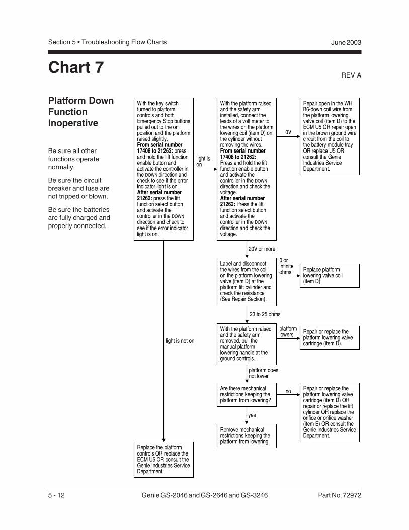
5 - 12 Genie GS-2046 and GS-2646 and GS-3246 Part No. 72972
REV A
Section 5 • Troubleshooting Flow Charts June 2003
Chart 7
Platform DownFunctionInoperative
Be sure all otherfunctions operatenormally.
Be sure the circuitbreaker and fuse arenot tripped or blown.
Be sure the batteriesare fully charged andproperly connected.
With the key switchturned to platformcontrols and bothEmergency Stop buttonspulled out to the onposition and the platformraised slightly,From serial number17408 to 21262: pressand hold the lift functionenable button andactivate the controller inthe DOWN direction andcheck to see if the errorindicator light is on.After serial number21262: press the liftfunction select buttonand activate thecontroller in the DOWNdirection and check tosee if the error indicatorlight is on.
light ison
light is not on
Label and disconnectthe wires from the coilon the platform loweringvalve (item D) at theplatform lift cylinder andcheck the resistance(See Repair Section).
0V
Repair open in the WHB6-down coil wire fromthe platform loweringvalve coil (item D) to theECM U5 OR repair openin the brown ground wirecircuit from the coil tothe battery module trayOR replace U5 ORconsult the GenieIndustries ServiceDepartment.
20V or more
0 orinfiniteohms
23 to 25 ohms
Replace platformlowering valve coil(item D).
Repair or replace theplatform lowering valvecartridge (item D).
Are there mechanicalrestrictions keeping theplatform from lowering?
With the platform raisedand the safety armremoved, pull themanual platformlowering handle at theground controls.
platform doesnot lower
platformlowers
With the platform raisedand the safety arminstalled, connect theleads of a volt meter tothe wires on the platformlowering coil (item D) onthe cylinder withoutremoving the wires.From serial number17408 to 21262:Press and hold the liftfunction enable buttonand activate thecontroller in the DOWNdirection and check thevoltage.After serial number21262: Press the liftfunction select buttonand activate thecontroller in the DOWNdirection and check thevoltage.
Repair or replace theplatform lowering valvecartridge (item D) ORrepair or replace the liftcylinder OR replace theorifice or orifice washer(item E) OR consult theGenie Industries ServiceDepartment.
Remove mechanicalrestrictions keeping theplatform from lowering.
yes
no
Replace the platformcontrols OR replace theECM U5 OR consult theGenie Industries ServiceDepartment.
Part No. 72972 Genie GS-2046 and GS-2646 and GS-3246 5 - 13
June 2003 Section 5 • Troubleshooting Flow Charts
REV A
This page intentionally left blank.
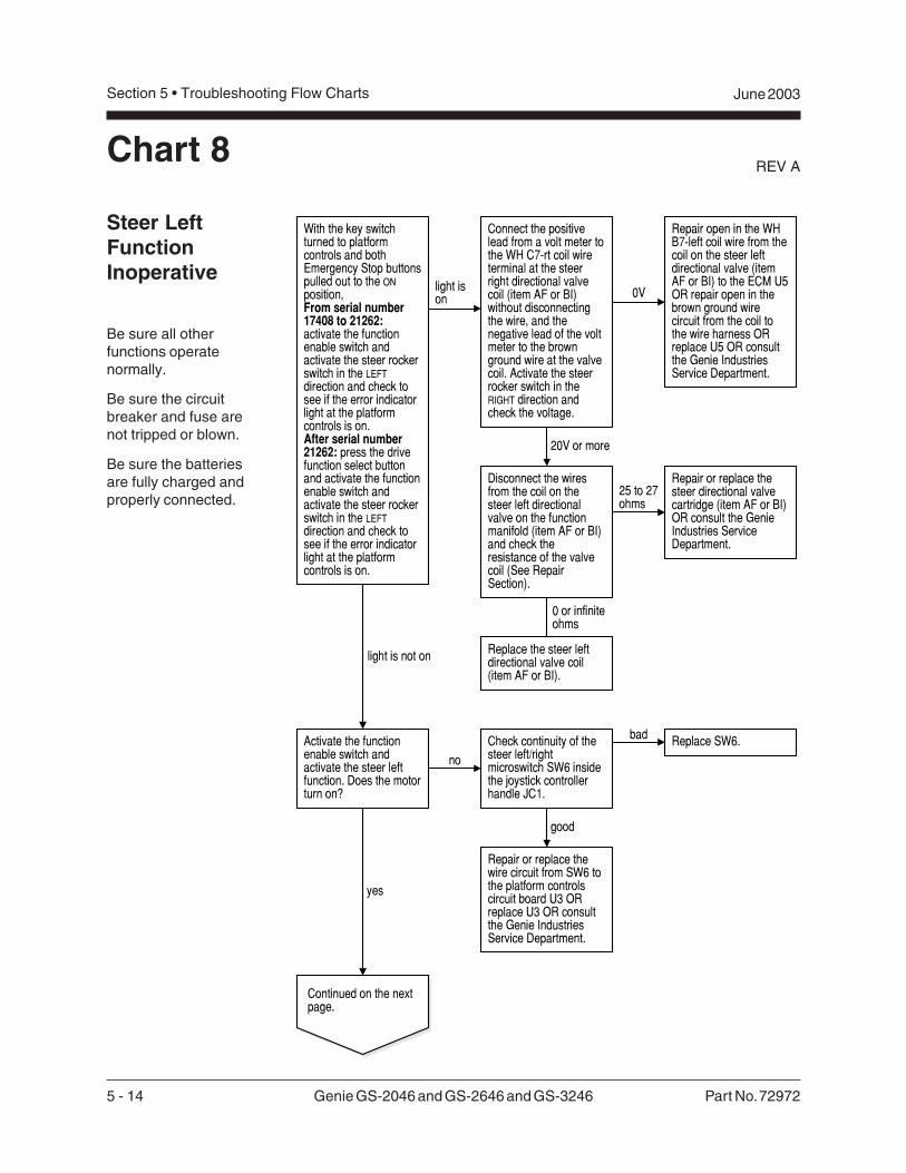
5 - 14 Genie GS-2046 and GS-2646 and GS-3246 Part No. 72972
REV A
Section 5 • Troubleshooting Flow Charts June 2003
Chart 8
Steer LeftFunctionInoperative
Be sure all otherfunctions operatenormally.
Be sure the circuitbreaker and fuse arenot tripped or blown.
Be sure the batteriesare fully charged andproperly connected.
no
With the key switchturned to platformcontrols and bothEmergency Stop buttonspulled out to the ONposition,From serial number17408 to 21262:activate the functionenable switch andactivate the steer rockerswitch in the LEFTdirection and check tosee if the error indicatorlight at the platformcontrols is on.After serial number21262: press the drivefunction select buttonand activate the functionenable switch andactivate the steer rockerswitch in the LEFTdirection and check tosee if the error indicatorlight at the platformcontrols is on.
light ison
light is not on
Disconnect the wiresfrom the coil on thesteer left directionalvalve on the functionmanifold (item AF or BI)and check theresistance of the valvecoil (See RepairSection).
0V
Repair open in the WHB7-left coil wire from thecoil on the steer leftdirectional valve (itemAF or BI) to the ECM U5OR repair open in thebrown ground wirecircuit from the coil tothe wire harness ORreplace U5 OR consultthe Genie IndustriesService Department.
20V or more
25 to 27ohms
0 or infiniteohms
Replace the steer leftdirectional valve coil(item AF or BI).
Repair or replace thesteer directional valvecartridge (item AF or BI)OR consult the GenieIndustries ServiceDepartment.
Activate the functionenable switch andactivate the steer leftfunction. Does the motorturn on?
Replace SW6.bad
yes
Continued on the nextpage.
Check continuity of thesteer left/rightmicroswitch SW6 insidethe joystick controllerhandle JC1.
good
Repair or replace thewire circuit from SW6 tothe platform controlscircuit board U3 ORreplace U3 OR consultthe Genie IndustriesService Department.
Connect the positivelead from a volt meter tothe WH C7-rt coil wireterminal at the steerright directional valvecoil (item AF or BI)without disconnectingthe wire, and thenegative lead of the voltmeter to the brownground wire at the valvecoil. Activate the steerrocker switch in theRIGHT direction andcheck the voltage.
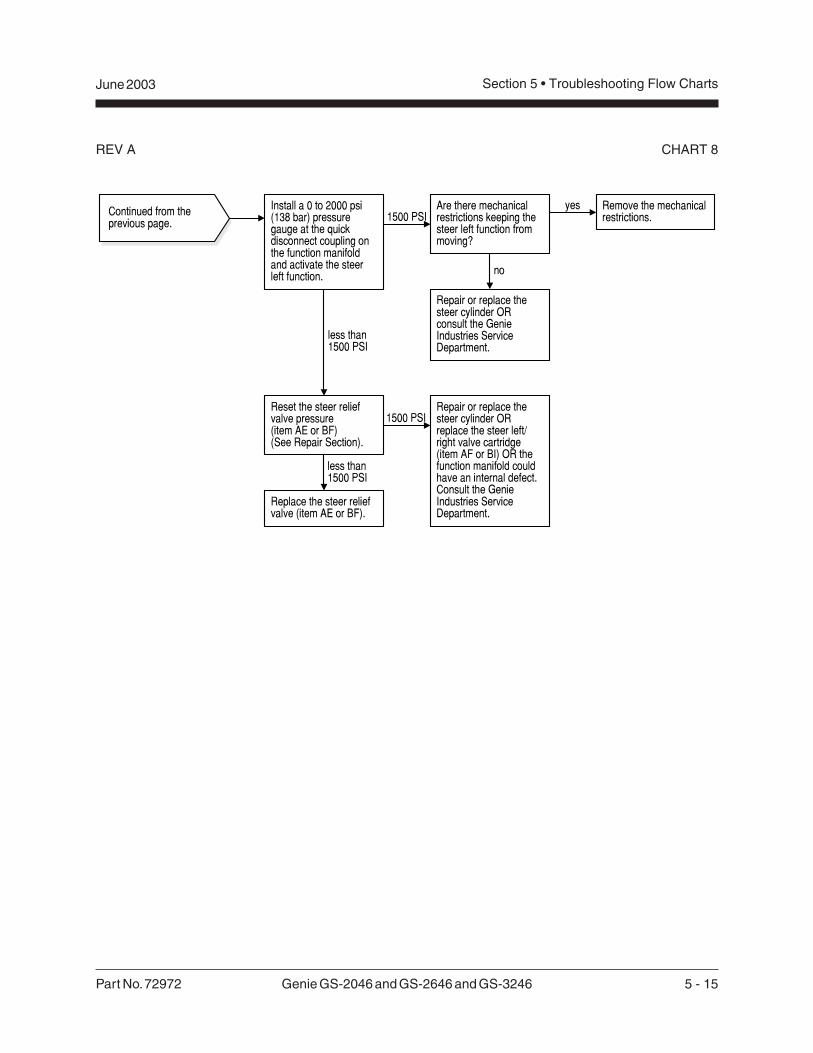
Part No. 72972 Genie GS-2046 and GS-2646 and GS-3246 5 - 15
June 2003 Section 5 • Troubleshooting Flow Charts
REV A CHART 8
Continued from theprevious page.
Install a 0 to 2000 psi(138 bar) pressuregauge at the quickdisconnect coupling onthe function manifoldand activate the steerleft function.
1500 PSI
less than1500 PSI
Repair or replace thesteer cylinder ORreplace the steer left/right valve cartridge(item AF or BI) OR thefunction manifold couldhave an internal defect.Consult the GenieIndustries ServiceDepartment.
Are there mechanicalrestrictions keeping thesteer left function frommoving?
Reset the steer reliefvalve pressure(item AE or BF)(See Repair Section).
less than1500 PSI
Remove the mechanicalrestrictions.
Repair or replace thesteer cylinder ORconsult the GenieIndustries ServiceDepartment.
yes
no
1500 PSI
Replace the steer reliefvalve (item AE or BF).
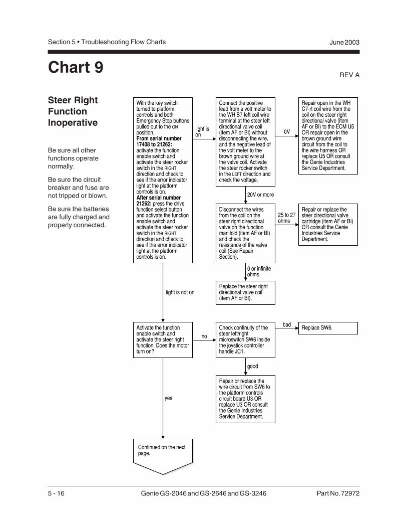
5 - 16 Genie GS-2046 and GS-2646 and GS-3246 Part No. 72972
REV A
Section 5 • Troubleshooting Flow Charts June 2003
Steer RightFunctionInoperative
Be sure all otherfunctions operatenormally.
Be sure the circuitbreaker and fuse arenot tripped or blown.
Be sure the batteriesare fully charged andproperly connected.
Chart 9
light is not on
With the key switchturned to platformcontrols and bothEmergency Stop buttonspulled out to the ONposition,From serial number17408 to 21262:activate the functionenable switch andactivate the steer rockerswitch in the RIGHTdirection and check tosee if the error indicatorlight at the platformcontrols is on.After serial number21262: press the drivefunction select buttonand activate the functionenable switch andactivate the steer rockerswitch in the RIGHTdirection and check tosee if the error indicatorlight at the platformcontrols is on.
light ison
Disconnect the wiresfrom the coil on thesteer right directionalvalve on the functionmanifold (item AF or BI)and check theresistance of the valvecoil (See RepairSection).
0V
Repair open in the WHC7-rt coil wire from thecoil on the steer rightdirectional valve (itemAF or BI) to the ECM U5OR repair open in thebrown ground wirecircuit from the coil tothe wire harness ORreplace U5 OR consultthe Genie IndustriesService Department.
20V or more
25 to 27ohms
Repair or replace thesteer directional valvecartridge (item AF or BI)OR consult the GenieIndustries ServiceDepartment.
Activate the functionenable switch andactivate the steer rightfunction. Does the motorturn on?
Replace SW6.
yes
Continued on the nextpage.
no
badCheck continuity of thesteer left/rightmicroswitch SW6 insidethe joystick controllerhandle JC1.
good
Repair or replace thewire circuit from SW6 tothe platform controlscircuit board U3 ORreplace U3 OR consultthe Genie IndustriesService Department.
Replace the steer rightdirectional valve coil(item AF or BI).
Connect the positivelead from a volt meter tothe WH B7-left coil wireterminal at the steer leftdirectional valve coil(item AF or BI) withoutdisconnecting the wire,and the negative lead ofthe volt meter to thebrown ground wire atthe valve coil. Activatethe steer rocker switchin the LEFT direction andcheck the voltage.
0 or infiniteohms

Part No. 72972 Genie GS-2046 and GS-2646 and GS-3246 5 - 17
June 2003 Section 5 • Troubleshooting Flow Charts
REV A CHART 9
Continued from theprevious page.
Install a 0 to 2000 psi(138 bar) pressuregauge at the quickdisconnect coupling onthe function manifoldand activate the steerright function.
Repair or replace thesteer cylinder ORreplace the steer left/right valve cartridge(item AF or BI) OR thefunction manifold couldhave an internal defect.Consult the GenieIndustries ServiceDepartment.
Are there mechanicalrestrictions keeping thesteer left function frommoving?
Reset the steer reliefvalve pressure(item AE or BF)(See Repair Section).
Remove the mechanicalrestrictions.
Repair or replace thesteer cylinder ORconsult the GenieIndustries ServiceDepartment.
yes
no
Replace the steer reliefvalve (item AE or BF).
1500 PSI
less than1500 PSI
less than1500 PSI
1500 PSI
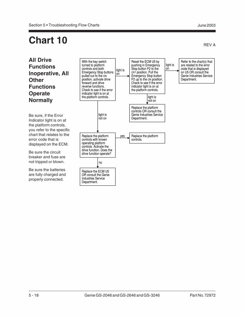
5 - 18 Genie GS-2046 and GS-2646 and GS-3246 Part No. 72972
REV A
Section 5 • Troubleshooting Flow Charts June 2003
All DriveFunctionsInoperative, AllOtherFunctionsOperateNormally
Be sure, if the ErrorIndicator light is on atthe platform controls,you refer to the specificchart that relates to theerror code that isdisplayed on the ECM.
Be sure the circuitbreaker and fuse arenot tripped or blown.
Be sure the batteriesare fully charged andproperly connected.
Chart 10
With the key switchturned to platformcontrols and bothEmergency Stop buttonspulled out to the ONposition, activate driveforward and drivereverse functions.Check to see if the errorindicator light is on atthe platform controls.
light ison
light isnot on
Reset the ECM U5 bypushing in EmergencyStop button P2 to theOFF position. Pull theEmergency Stop buttonP2 up to the ON position.Check to see if the errorindicator light is on atthe platform controls.
Refer to the chart(s) thatare related to the errorcode that is displayedon U5 OR consult theGenie Industries ServiceDepartment.
Replace the ECM U5OR consult the GenieIndustries ServiceDepartment.
light ison
light isnot on
Replace the platformcontrols OR consult theGenie Industries ServiceDepartment.
Replace the platformcontrols with knownoperating platformcontrols. Activate thedrive function. Does thedrive function operate?
Replace the platformcontrols.
yes
no
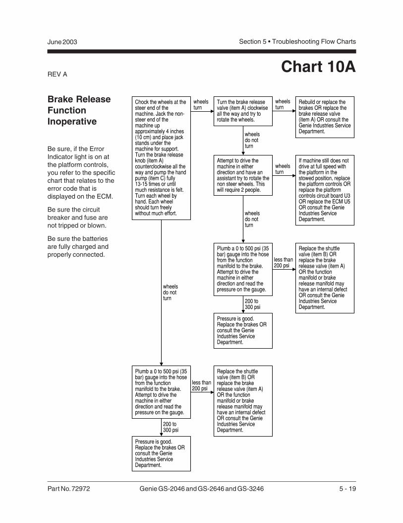
Part No. 72972 Genie GS-2046 and GS-2646 and GS-3246 5 - 19
June 2003 Section 5 • Troubleshooting Flow Charts
REV A
Brake ReleaseFunctionInoperative
Be sure, if the ErrorIndicator light is on atthe platform controls,you refer to the specificchart that relates to theerror code that isdisplayed on the ECM.
Be sure the circuitbreaker and fuse arenot tripped or blown.
Be sure the batteriesare fully charged andproperly connected.
Chart 10A
wheelsturn
Turn the brake releasevalve (item A) clockwiseall the way and try torotate the wheels.
Chock the wheels at thesteer end of themachine. Jack the non-steer end of themachine upapproximately 4 inches(10 cm) and place jackstands under themachine for support.Turn the brake releaseknob (item A)counterclockwise all theway and pump the handpump (item C) fully13-15 times or untilmuch resistance is felt.Turn each wheel byhand. Each wheelshould turn freelywithout much effort.
wheelsturn
wheelsdo notturn
Rebuild or replace thebrakes OR replace thebrake release valve(item A) OR consult theGenie Industries ServiceDepartment.
Attempt to drive themachine in eitherdirection and have anassistant try to rotate thenon steer wheels. Thiswill require 2 people.
wheelsturn
If machine still does notdrive at full speed withthe platform in thestowed position, replacethe platform controls ORreplace the platformcontrols circuit board U3OR replace the ECM U5OR consult the GenieIndustries ServiceDepartment.
wheelsdo notturn
Plumb a 0 to 500 psi (35bar) gauge into the hosefrom the functionmanifold to the brake.Attempt to drive themachine in eitherdirection and read thepressure on the gauge.
less than200 psi
Pressure is good.Replace the brakes ORconsult the GenieIndustries ServiceDepartment.
200 to300 psi
Replace the shuttlevalve (item B) ORreplace the brakerelease valve (item A)OR the functionmanifold or brakerelease manifold mayhave an internal defectOR consult the GenieIndustries ServiceDepartment.
wheelsdo notturn
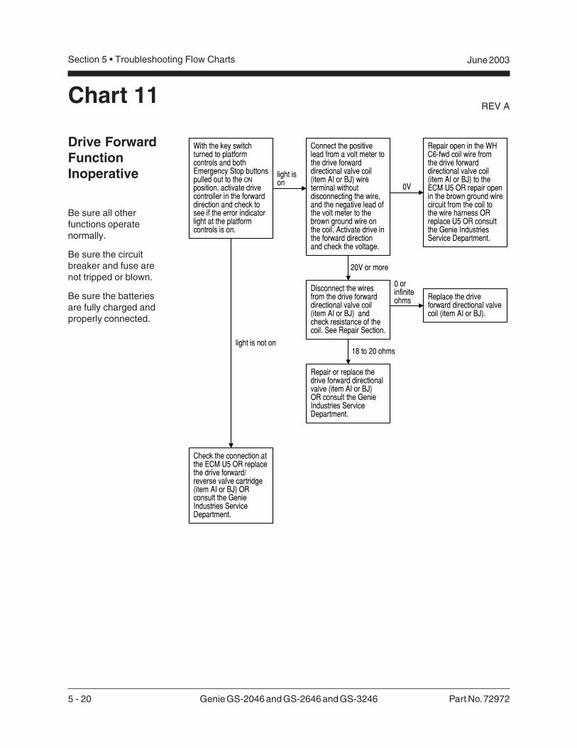
5 - 20 Genie GS-2046 and GS-2646 and GS-3246 Part No. 72972
REV A
Section 5 • Troubleshooting Flow Charts June 2003
Drive ForwardFunctionInoperative
Be sure all otherfunctions operatenormally.
Be sure the circuitbreaker and fuse arenot tripped or blown.
Be sure the batteriesare fully charged andproperly connected.
Chart 11
With the key switchturned to platformcontrols and bothEmergency Stop buttonspulled out to the ONposition, activate drivecontroller in the forwarddirection and check tosee if the error indicatorlight at the platformcontrols is on.
light ison
light is not on
Connect the positivelead from a volt meter tothe drive forwarddirectional valve coil(item AI or BJ) wireterminal withoutdisconnecting the wire,and the negative lead ofthe volt meter to thebrown ground wire onthe coil. Activate drive inthe forward directionand check the voltage.
Disconnect the wiresfrom the drive forwarddirectional valve coil(item AI or BJ) andcheck resistance of thecoil. See Repair Section.
0V
Repair open in the WHC6-fwd coil wire fromthe drive forwarddirectional valve coil(item AI or BJ) to theECM U5 OR repair openin the brown ground wirecircuit from the coil tothe wire harness ORreplace U5 OR consultthe Genie IndustriesService Department.
20V or more
0 orinfiniteohms
18 to 20 ohms
Replace the driveforward directional valvecoil (item AI or BJ).
Repair or replace thedrive forward directionalvalve (item AI or BJ)OR consult the GenieIndustries ServiceDepartment.
Check the connection atthe ECM U5 OR replacethe drive forward/reverse valve cartridge(item AI or BJ) ORconsult the GenieIndustries ServiceDepartment.
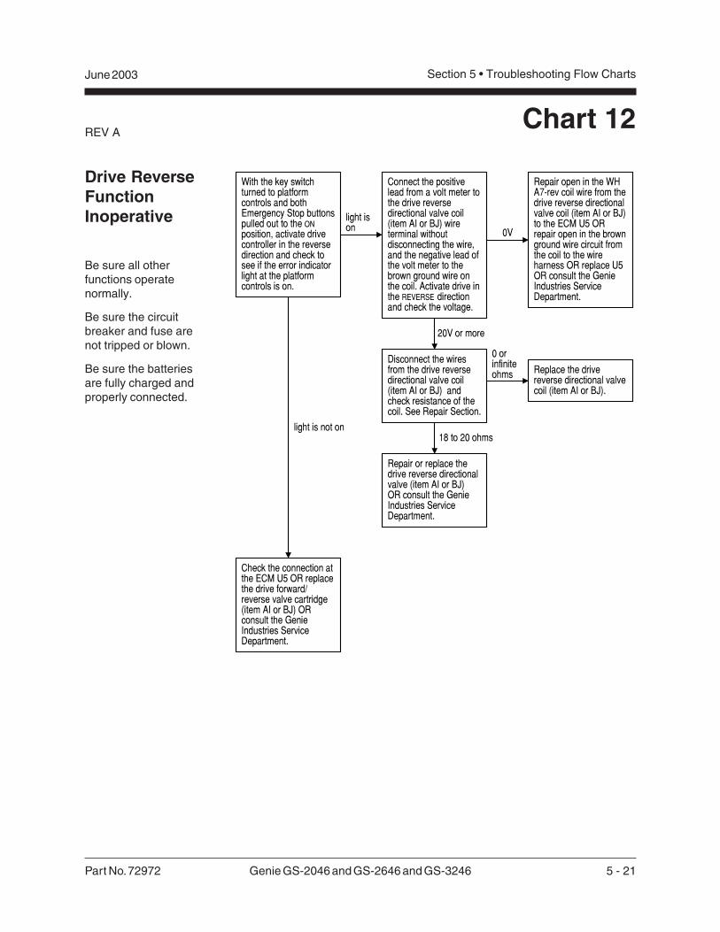
Part No. 72972 Genie GS-2046 and GS-2646 and GS-3246 5 - 21
June 2003 Section 5 • Troubleshooting Flow Charts
REV AChart 12
Drive ReverseFunctionInoperative
Be sure all otherfunctions operatenormally.
Be sure the circuitbreaker and fuse arenot tripped or blown.
Be sure the batteriesare fully charged andproperly connected.
With the key switchturned to platformcontrols and bothEmergency Stop buttonspulled out to the ONposition, activate drivecontroller in the reversedirection and check tosee if the error indicatorlight at the platformcontrols is on.
light ison
light is not on
Connect the positivelead from a volt meter tothe drive reversedirectional valve coil(item AI or BJ) wireterminal withoutdisconnecting the wire,and the negative lead ofthe volt meter to thebrown ground wire onthe coil. Activate drive inthe REVERSE directionand check the voltage.
Disconnect the wiresfrom the drive reversedirectional valve coil(item AI or BJ) andcheck resistance of thecoil. See Repair Section.
0V
Repair open in the WHA7-rev coil wire from thedrive reverse directionalvalve coil (item AI or BJ)to the ECM U5 ORrepair open in the brownground wire circuit fromthe coil to the wireharness OR replace U5OR consult the GenieIndustries ServiceDepartment.
20V or more
0 orinfiniteohms
18 to 20 ohms
Replace the drivereverse directional valvecoil (item AI or BJ).
Repair or replace thedrive reverse directionalvalve (item AI or BJ)OR consult the GenieIndustries ServiceDepartment.
Check the connection atthe ECM U5 OR replacethe drive forward/reverse valve cartridge(item AI or BJ) ORconsult the GenieIndustries ServiceDepartment.
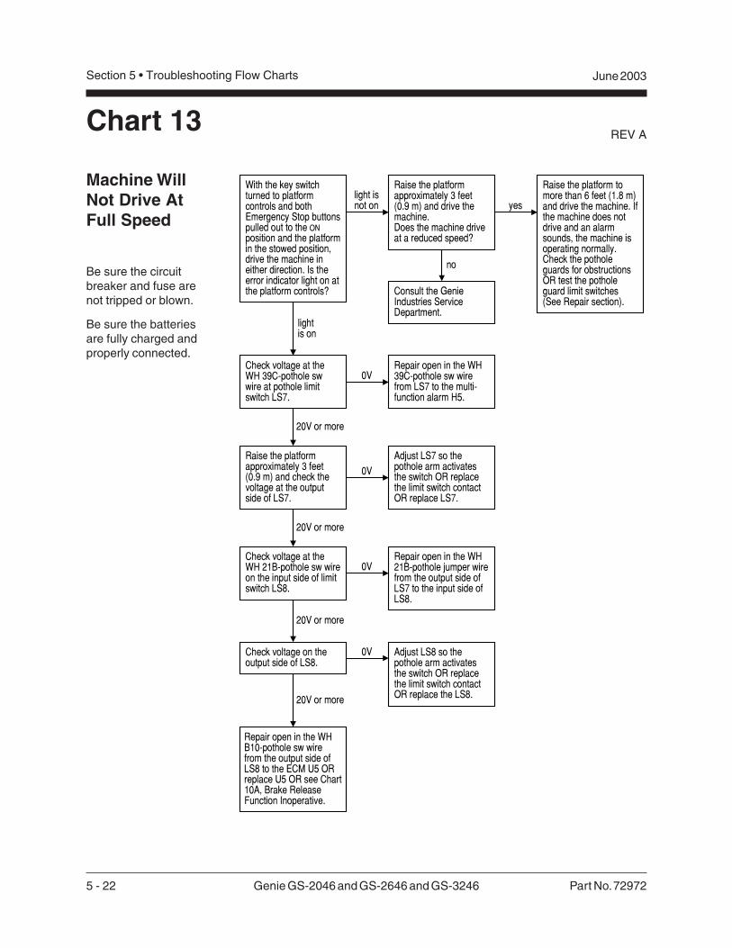
5 - 22 Genie GS-2046 and GS-2646 and GS-3246 Part No. 72972
REV A
Section 5 • Troubleshooting Flow Charts June 2003
Machine WillNot Drive AtFull Speed
Be sure the circuitbreaker and fuse arenot tripped or blown.
Be sure the batteriesare fully charged andproperly connected.
Chart 13
With the key switchturned to platformcontrols and bothEmergency Stop buttonspulled out to the ONposition and the platformin the stowed position,drive the machine ineither direction. Is theerror indicator light on atthe platform controls?
light isnot on
Check voltage at theWH 39C-pothole swwire at pothole limitswitch LS7.
lightis on
0V
20V or more
Raise the platformapproximately 3 feet(0.9 m) and drive themachine.Does the machine driveat a reduced speed?
Repair open in the WH39C-pothole sw wirefrom LS7 to the multi-function alarm H5.
Check voltage at theWH 21B-pothole sw wireon the input side of limitswitch LS8.
Repair open in the WH21B-pothole jumper wirefrom the output side ofLS7 to the input side ofLS8.
Check voltage on theoutput side of LS8.
Adjust LS8 so thepothole arm activatesthe switch OR replacethe limit switch contactOR replace the LS8.
no
yes
Raise the platform tomore than 6 feet (1.8 m)and drive the machine. Ifthe machine does notdrive and an alarmsounds, the machine isoperating normally.Check the potholeguards for obstructionsOR test the potholeguard limit switches(See Repair section).
Consult the GenieIndustries ServiceDepartment.
Raise the platformapproximately 3 feet(0.9 m) and check thevoltage at the outputside of LS7.
Adjust LS7 so thepothole arm activatesthe switch OR replacethe limit switch contactOR replace LS7.
20V or more
0V
0V
20V or more
0V
20V or more
Repair open in the WHB10-pothole sw wirefrom the output side ofLS8 to the ECM U5 ORreplace U5 OR see Chart10A, Brake ReleaseFunction Inoperative.
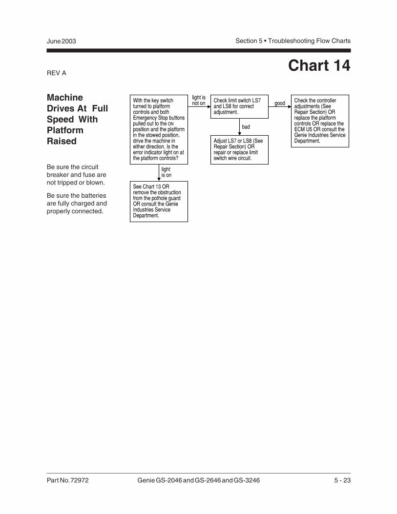
Part No. 72972 Genie GS-2046 and GS-2646 and GS-3246 5 - 23
June 2003 Section 5 • Troubleshooting Flow Charts
REV AChart 14
MachineDrives At FullSpeed WithPlatformRaised
Be sure the circuitbreaker and fuse arenot tripped or blown.
Be sure the batteriesare fully charged andproperly connected.
light isnot on
lightis on
See Chart 13 ORremove the obstructionfrom the pothole guardOR consult the GenieIndustries ServiceDepartment.
Check limit switch LS7and LS8 for correctadjustment.
With the key switchturned to platformcontrols and bothEmergency Stop buttonspulled out to the ONposition and the platformin the stowed position,drive the machine ineither direction. Is theerror indicator light on atthe platform controls?
Check the controlleradjustments (SeeRepair Section) ORreplace the platformcontrols OR replace theECM U5 OR consult theGenie Industries ServiceDepartment.Adjust LS7 or LS8 (See
Repair Section) ORrepair or replace limitswitch wire circuit.
good
bad
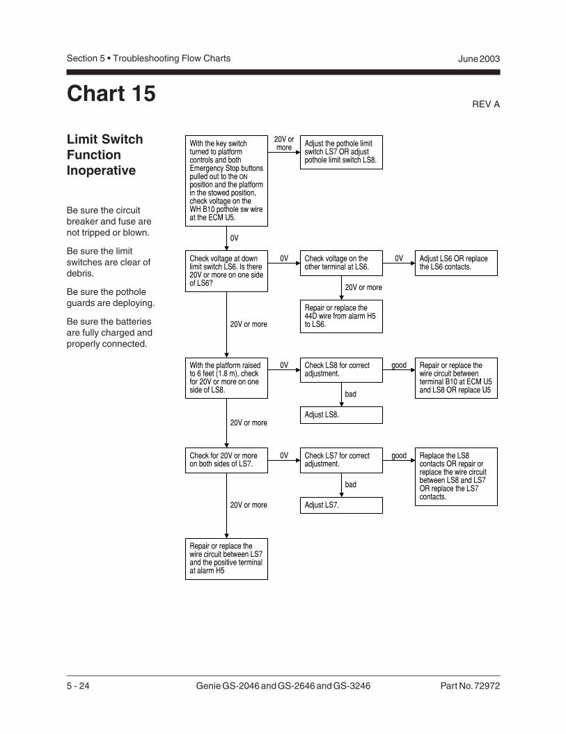
5 - 24 Genie GS-2046 and GS-2646 and GS-3246 Part No. 72972
REV A
Section 5 • Troubleshooting Flow Charts June 2003
Limit SwitchFunctionInoperative
Be sure the circuitbreaker and fuse arenot tripped or blown.
Be sure the limitswitches are clear ofdebris.
Be sure the potholeguards are deploying.
Be sure the batteriesare fully charged andproperly connected.
Chart 15
20V ormore
0V
Adjust the pothole limitswitch LS7 OR adjustpothole limit switch LS8.
With the key switchturned to platformcontrols and bothEmergency Stop buttonspulled out to the ONposition and the platformin the stowed position,check voltage on theWH B10 pothole sw wireat the ECM U5.
20V or more
0V Check voltage on theother terminal at LS6.
With the platform raisedto 6 feet (1.8 m), checkfor 20V or more on oneside of LS8.
0V
0V Adjust LS6 OR replacethe LS6 contacts.
20V or more
Repair or replace the44D wire from alarm H5to LS6.
Repair or replace thewire circuit between LS7and the positive terminalat alarm H5
20V or more
Repair or replace thewire circuit betweenterminal B10 at ECM U5and LS8 OR replace U5
Check voltage at downlimit switch LS6. Is there20V or more on one sideof LS6?
Check LS8 for correctadjustment.
Adjust LS8.
good
bad
Check for 20V or moreon both sides of LS7.
0V
20V or more
Replace the LS8contacts OR repair orreplace the wire circuitbetween LS8 and LS7OR replace the LS7contacts.
Check LS7 for correctadjustment.
Adjust LS7.
good
bad
Part No. 72972 Genie GS-2046 and GS-2646 and GS-3246 5 - 25
June 2003 Section 5 • Troubleshooting Flow Charts
REV A
This page intentionally left blank.
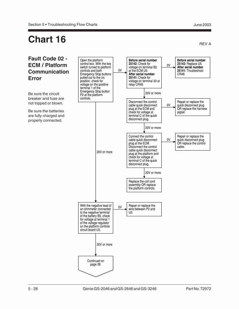
5 - 26 Genie GS-2046 and GS-2646 and GS-3246 Part No. 72972
REV A
Section 5 • Troubleshooting Flow Charts June 2003
Chart 16
Fault Code 02 -ECM / PlatformCommunicationError
Be sure the circuitbreaker and fuse arenot tripped or blown.
Be sure the batteriesare fully charged andproperly connected.
Open the platformcontrol box. With the keyswitch turned to platformcontrols and bothEmergency Stop buttonspulled out to the ONposition, check forvoltage on the positiveterminal 1 of theEmergency Stop buttonP2 at the platformcontrols.
0V
20V or more
Continued onpage 28.
0V
20V or more
Before serial number25142: Check forvoltage on terminal B2at the ECM U5.After serial number25141: Check forvoltage on terminal 30 atrelay CR48.
Disconnect the controlcable quick disconnectplug at the ECM andcheck for voltage atterminal C of the quickdisconnect plug.
20V or more
Connect the controlcable quick disconnectplug at the ECM.Disconnect the controlcable quick disconnectplug at the platform andcheck for voltage atterminal C of the quickdisconnect plug.
0VRepair or replace thequick disconnect plugOR replace the harnesspigtail.
0VRepair or replace thequick disconnect plugOR replace the controlcable.
20V or more
Replace the coil cordassembly OR replacethe platform controls.
20V or more
With the negative lead ofan ohmmeter connectedto the negative terminalof the battery B5, checkfor voltage at terminal 1of the voltage regulatoron the platform controlscircuit board U3.
0V Repair or replace thewire between P2 andU3.
Before serial number25142: Replace U5.After serial number25141: TroubleshootCR48.
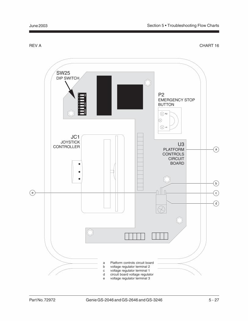
Part No. 72972 Genie GS-2046 and GS-2646 and GS-3246 5 - 27
June 2003 Section 5 • Troubleshooting Flow Charts
REV A CHART 16
a Platform controls circuit boardb voltage regulator terminal 2c voltage regulator terminal 1d circuit board voltage regulatore voltage regulator terminal 3
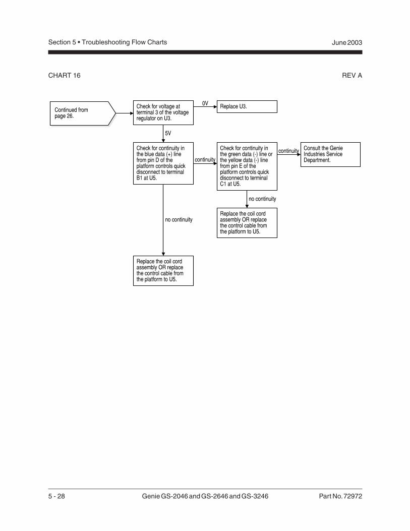
5 - 28 Genie GS-2046 and GS-2646 and GS-3246 Part No. 72972
REV A
Section 5 • Troubleshooting Flow Charts June 2003
CHART 16
Continued frompage 26.
5V
Check for voltage atterminal 3 of the voltageregulator on U3.
0V Replace U3.
Check for continuity inthe blue data (+) linefrom pin D of theplatform controls quickdisconnect to terminalB1 at U5.
no continuity
continuity
Replace the coil cordassembly OR replacethe control cable fromthe platform to U5.
Check for continuity inthe green data (-) line orthe yellow data (-) linefrom pin E of theplatform controls quickdisconnect to terminalC1 at U5.
continuity Consult the GenieIndustries ServiceDepartment.
no continuity
Replace the coil cordassembly OR replacethe control cable fromthe platform to U5.
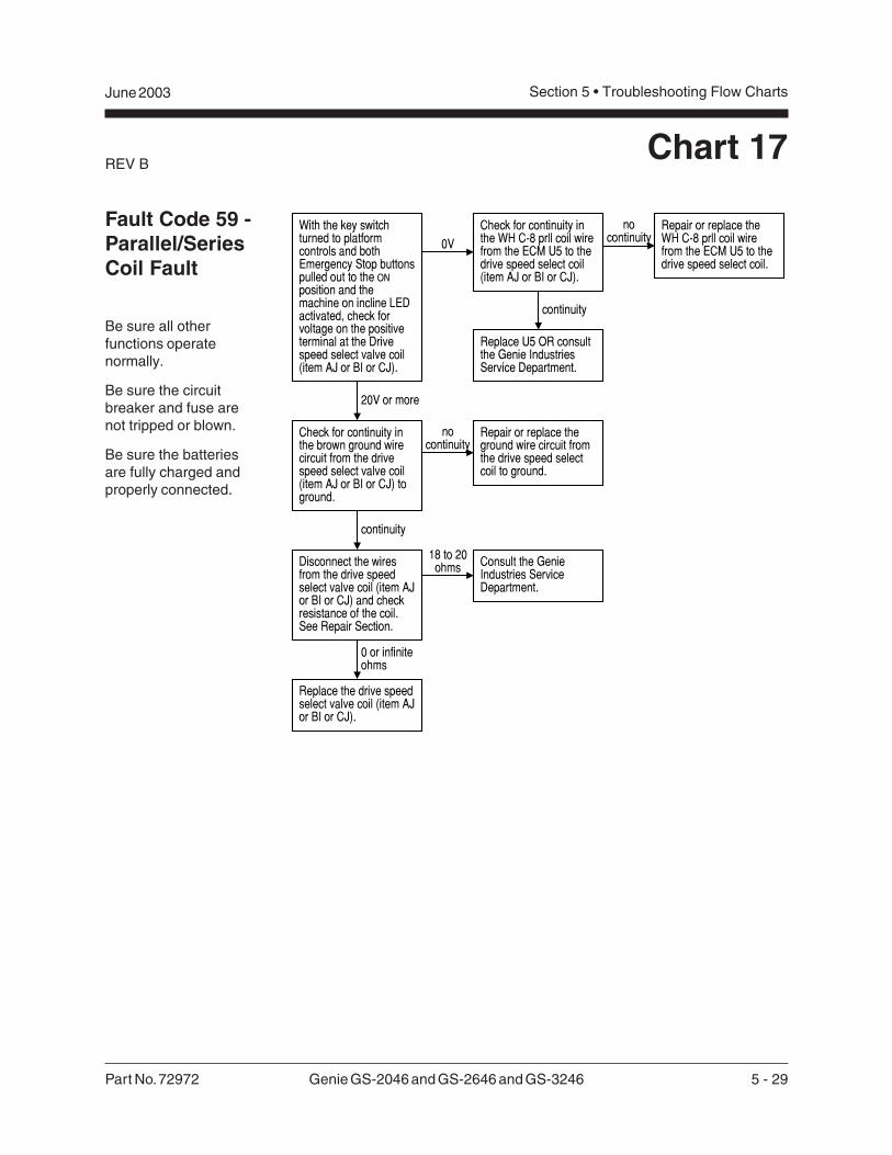
Part No. 72972 Genie GS-2046 and GS-2646 and GS-3246 5 - 29
June 2003 Section 5 • Troubleshooting Flow Charts
REV BChart 17
Fault Code 59 -Parallel/SeriesCoil Fault
Be sure all otherfunctions operatenormally.
Be sure the circuitbreaker and fuse arenot tripped or blown.
Be sure the batteriesare fully charged andproperly connected.
With the key switchturned to platformcontrols and bothEmergency Stop buttonspulled out to the ONposition and themachine on incline LEDactivated, check forvoltage on the positiveterminal at the Drivespeed select valve coil(item AJ or BI or CJ).
0VCheck for continuity inthe WH C-8 prll coil wirefrom the ECM U5 to thedrive speed select coil(item AJ or BI or CJ).
20V or more
Check for continuity inthe brown ground wirecircuit from the drivespeed select valve coil(item AJ or BI or CJ) toground.
nocontinuity
0 or infiniteohms
Repair or replace theground wire circuit fromthe drive speed selectcoil to ground.
Consult the GenieIndustries ServiceDepartment.
Disconnect the wiresfrom the drive speedselect valve coil (item AJor BI or CJ) and checkresistance of the coil.See Repair Section.
18 to 20ohms
Replace the drive speedselect valve coil (item AJor BI or CJ).
continuity
Repair or replace theWH C-8 prll coil wirefrom the ECM U5 to thedrive speed select coil.
Replace U5 OR consultthe Genie IndustriesService Department.
nocontinuity
continuity
5 - 30 Genie GS-2046 and GS-2646 and GS-3246 Part No. 72972
REV A
Section 5 • Troubleshooting Flow Charts June 2003
This page intentionally left blank.
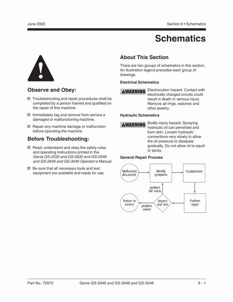
Part No. 72972 Genie GS-2046 and GS-2646 and GS-3246 6 - 1
Section 6 • SchematicsJune 2003
Schematics
Observe and Obey:
Troubleshooting and repair procedures shall becompleted by a person trained and qualified onthe repair of this machine.
Immediately tag and remove from service adamaged or malfunctioning machine.
Repair any machine damage or malfunctionbefore operating the machine.
Before Troubleshooting:
Read, understand and obey the safety rulesand operating instructions printed in theGenie GS-2032 and GS-2632 and GS-2046and GS-2646 and GS-3246 Operator's Manual.
Be sure that all necessary tools and testequipment are available and ready for use.
About This SectionThere are two groups of schematics in this section.An illustration legend precedes each group ofdrawings.
Electrical Schematics
Electrocution hazard. Contact withelectrically charged circuits couldresult in death or serious injury.Remove all rings, watches andother jewelry.
Hydraulic Schematics
Bodily injury hazard. Sprayinghydraulic oil can penetrate andburn skin. Loosen hydraulicconnections very slowly to allowthe oil pressure to dissipategradually. Do not allow oil to squirtor spray.
General Repair Process
Malfunctiondiscovered
Identifysymptoms
Troubleshoot
Performrepair
Return toservice problem
solved
problemstill exists
Inspectand test
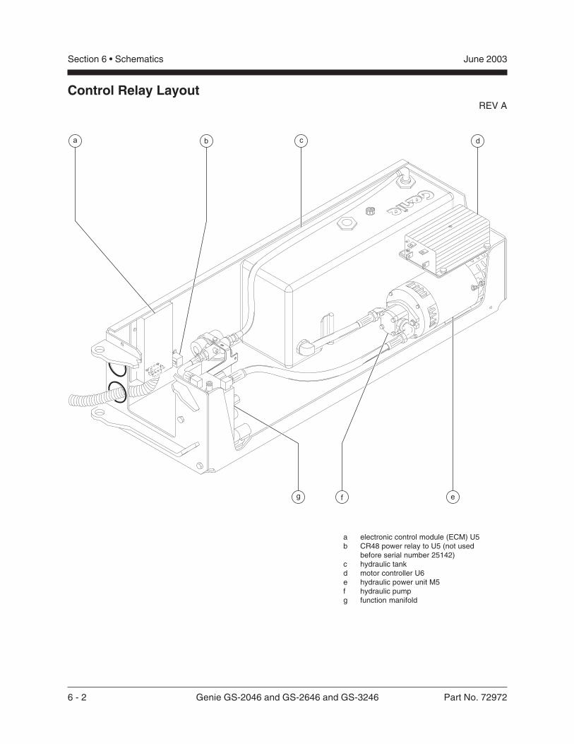
6 - 2 Genie GS-2046 and GS-2646 and GS-3246 Part No. 72972
Section 6 • Schematics June 2003
REV A
Control Relay Layout
a electronic control module (ECM) U5b CR48 power relay to U5 (not used
before serial number 25142)c hydraulic tankd motor controller U6e hydraulic power unit M5f hydraulic pumpg function manifold
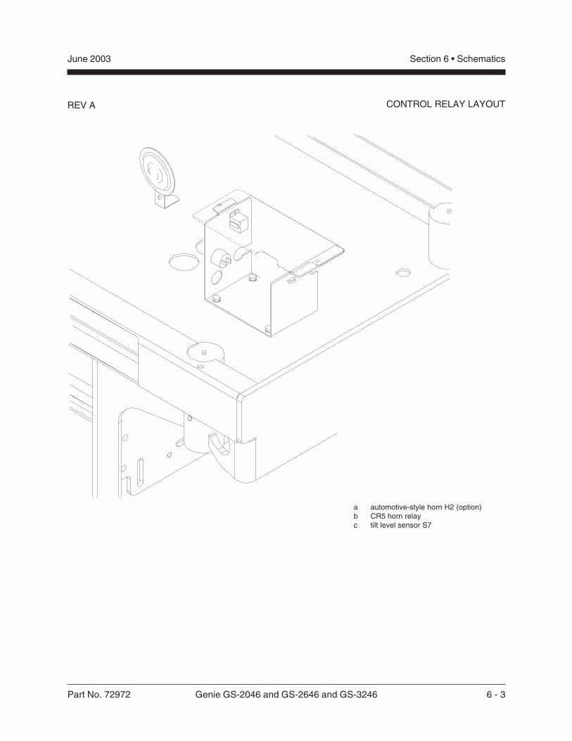
Part No. 72972 Genie GS-2046 and GS-2646 and GS-3246 6 - 3
Section 6 • SchematicsJune 2003
REV A CONTROL RELAY LAYOUT
a automotive-style horn H2 (option)b CR5 horn relayc tilt level sensor S7
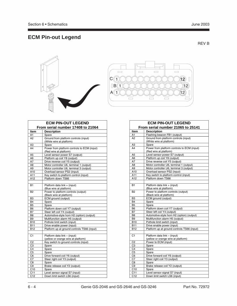
6 - 4 Genie GS-2046 and GS-2646 and GS-3246 Part No. 72972
Section 6 • Schematics June 2003
REV B
ECM Pin-out Legend
ECM PIN-OUT LEGENDFrom serial number 17408 to 21064
Item DescriptionA1 SpareA2 Ground from platform controls (input)
(White wire at platform)A3 SpareA4 Power from platform controls to ECM (input)
(Red wire at platform)A5 Level sensor power S7 (output)A6 Platform up coil Y8 (output)A7 Drive reverse coil Y5 (output)A8 Motor controller U6, terminal 1 (output)A9 Motor controller U6, terminal 3 (output)A10 Overload sensor PS2 (input)A11 Key switch to platform control (input)A12 Platform down TS66
B1 Platform data link + (input)(Blue wire at platform)
B2 Power to platform controls (output)(Black wire at platform)
B3 ECM ground (output)B4 SpareB5 SpareB6 Platform down coil Y7 (output)B7 Steer left coil Y4 (output)B8 Automotive-style horn H2 (option) (output)B9 Multifunction alarm H5 (output)B10 Pothole limit switch (input)B11 Drive enable power (input)B12 Platform up at ground controls TS66 (input)
C1 Platform data link – (input)(yellow or orange wire at platform)
C2 Key switch to ground controls (input)C3 SpareC4 SpareC5 SpareC6 Drive forward coil Y6 (output)C7 Steer right coil Y3 (output)C8 SpareC9 Brake release coil Y2 (output)C10 SpareC11 Level sensor signal S7 (input)C12 Down limit switch LS6 (input)
ECM PIN-OUT LEGENDFrom serial number 21065 to 25141
Item DescriptionA1 Flashing beacon FB1 (output)A2 Ground from platform controls (input)
(White wire at platform)A3 SpareA4 Power from platform controls to ECM (input)
(Red wire at platform)A5 Level sensor power S7 (output)A6 Platform up coil Y8 (output)A7 Drive reverse coil Y5 (output)A8 Motor controller U6, terminal 1 (output)A9 Motor controller U6, terminal 3 (output)A10 Overload sensor PS2 (input)A11 Key switch to platform control (input)A12 Platform down TS66
B1 Platform data link + (input)(Blue wire at platform)
B2 Power to platform controls (output)(Black wire at platform)
B3 ECM ground (output)B4 SpareB5 SpareB6 Platform down coil Y7 (output)B7 Steer left coil Y4 (output)B8 Automotive-style horn H2 (option) (output)B9 Multifunction alarm H5 (output)B10 Pothole limit switch (input)B11 Drive enable power (input)B12 Platform up at ground controls TS66 (input)
C1 Platform data link – (input)(yellow or orange wire at platform)
C2 Power to ECM (input)C3 SpareC4 SpareC5 SpareC6 Drive forward coil Y6 (output)C7 Steer right coil Y3 (output)C8 SpareC9 Brake release coil Y2 (output)C10 SpareC11 Level sensor signal S7 (input)C12 Down limit switch LS6 (input)
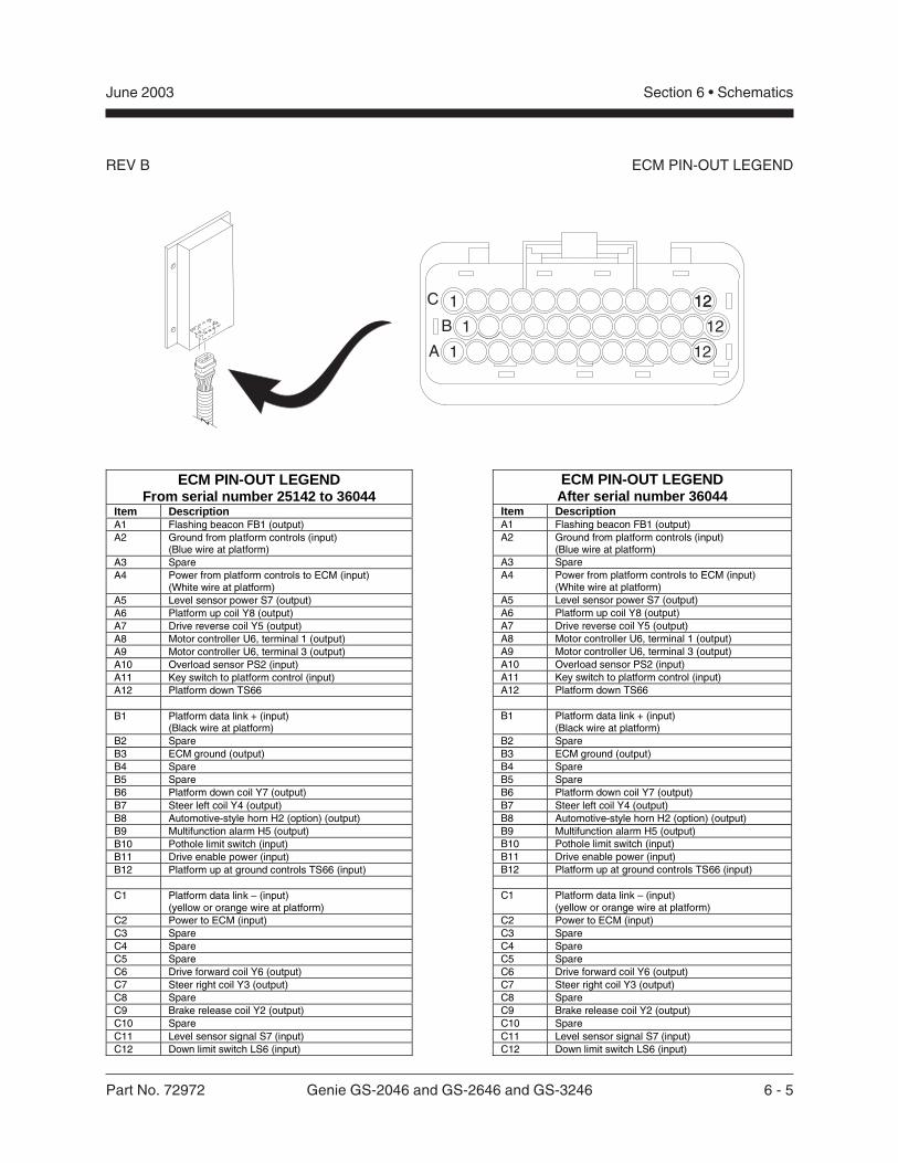
Part No. 72972 Genie GS-2046 and GS-2646 and GS-3246 6 - 5
Section 6 • SchematicsJune 2003
REV B ECM PIN-OUT LEGEND
ECM PIN-OUT LEGENDFrom serial number 25142 to 36044
Item DescriptionA1 Flashing beacon FB1 (output)A2 Ground from platform controls (input)
(Blue wire at platform)A3 SpareA4 Power from platform controls to ECM (input)
(White wire at platform)A5 Level sensor power S7 (output)A6 Platform up coil Y8 (output)A7 Drive reverse coil Y5 (output)A8 Motor controller U6, terminal 1 (output)A9 Motor controller U6, terminal 3 (output)A10 Overload sensor PS2 (input)A11 Key switch to platform control (input)A12 Platform down TS66
B1 Platform data link + (input)(Black wire at platform)
B2 SpareB3 ECM ground (output)B4 SpareB5 SpareB6 Platform down coil Y7 (output)B7 Steer left coil Y4 (output)B8 Automotive-style horn H2 (option) (output)B9 Multifunction alarm H5 (output)B10 Pothole limit switch (input)B11 Drive enable power (input)B12 Platform up at ground controls TS66 (input)
C1 Platform data link – (input)(yellow or orange wire at platform)
C2 Power to ECM (input)C3 SpareC4 SpareC5 SpareC6 Drive forward coil Y6 (output)C7 Steer right coil Y3 (output)C8 SpareC9 Brake release coil Y2 (output)C10 SpareC11 Level sensor signal S7 (input)C12 Down limit switch LS6 (input)
ECM PIN-OUT LEGENDAfter serial number 36044
Item DescriptionA1 Flashing beacon FB1 (output)A2 Ground from platform controls (input)
(Blue wire at platform)A3 SpareA4 Power from platform controls to ECM (input)
(White wire at platform)A5 Level sensor power S7 (output)A6 Platform up coil Y8 (output)A7 Drive reverse coil Y5 (output)A8 Motor controller U6, terminal 1 (output)A9 Motor controller U6, terminal 3 (output)A10 Overload sensor PS2 (input)A11 Key switch to platform control (input)A12 Platform down TS66
B1 Platform data link + (input)(Black wire at platform)
B2 SpareB3 ECM ground (output)B4 SpareB5 SpareB6 Platform down coil Y7 (output)B7 Steer left coil Y4 (output)B8 Automotive-style horn H2 (option) (output)B9 Multifunction alarm H5 (output)B10 Pothole limit switch (input)B11 Drive enable power (input)B12 Platform up at ground controls TS66 (input)
C1 Platform data link – (input)(yellow or orange wire at platform)
C2 Power to ECM (input)C3 SpareC4 SpareC5 SpareC6 Drive forward coil Y6 (output)C7 Steer right coil Y3 (output)C8 SpareC9 Brake release coil Y2 (output)C10 SpareC11 Level sensor signal S7 (input)C12 Down limit switch LS6 (input)
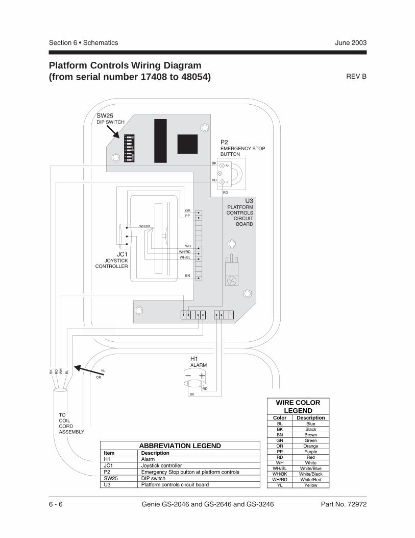
6 - 6 Genie GS-2046 and GS-2646 and GS-3246 Part No. 72972
Section 6 • Schematics June 2003
REV B
Platform Controls Wiring Diagram(from serial number 17408 to 48054)
P2EMERGENCY STOPBUTTON
JC1JOYSTICK
CONTROLLER
H1ALARM
21
BK
RD
RD
BK
RD
RD YL
OR
BK
BL
WH
TOCOILCORDASSEMBLY
WH
BN
WH/BK
WH/RD
WH/BL
SW25DIP SWITCH
OR
PP
U3PLATFORMCONTROLS
CIRCUITBOARD
12
34
56
78
ON
AL
CO
AD
FO
8S
OE
ABBREVIATION LEGENDItem DescriptionH1 AlarmJC1 Joystick controllerP2 Emergency Stop button at platform controlsSW25 DIP switchU3 Platform controls circuit board
WIRE COLORLEGEND
Color DescriptionBL BlueBK BlackBN BrownGN GreenOR OrangePP PurpleRD RedWH White
WH/BL White/BlueWH/BK White/BlackWH/RD White/Red
YL Yellow
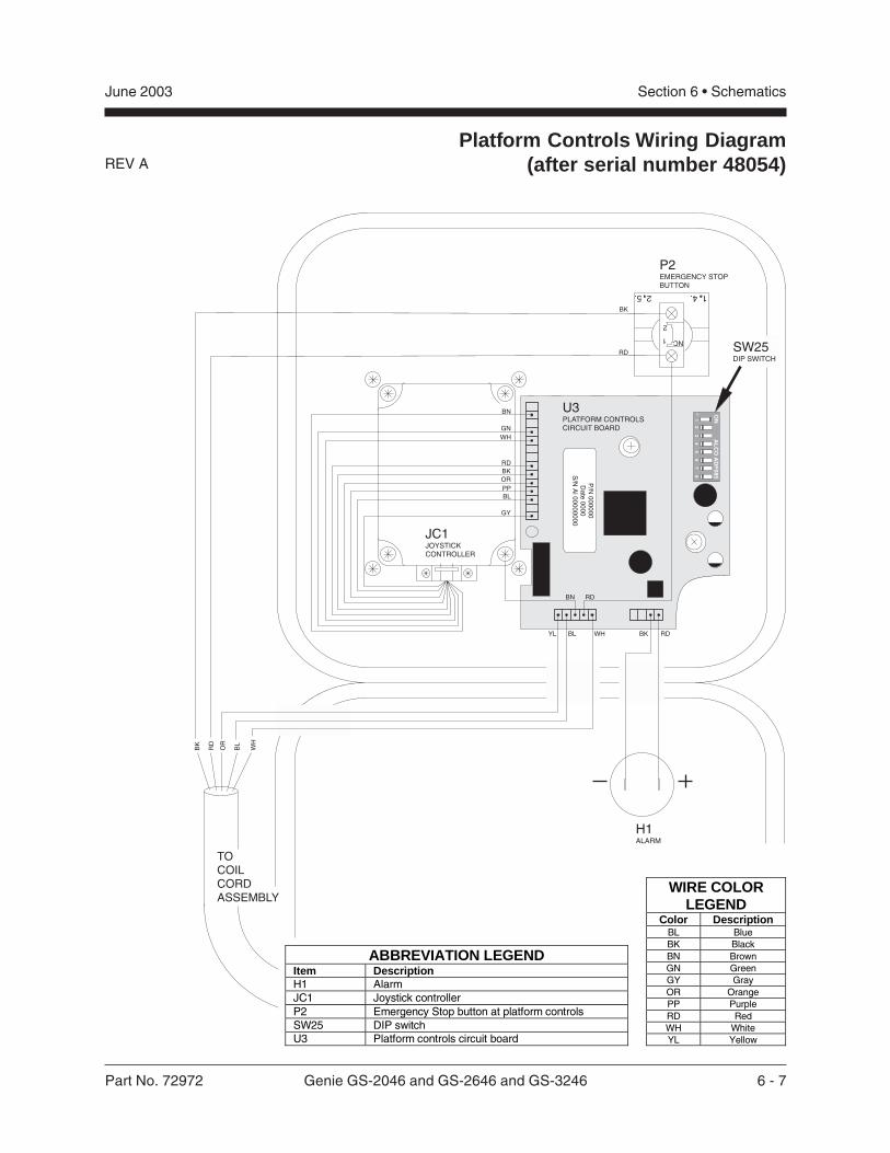
Part No. 72972 Genie GS-2046 and GS-2646 and GS-3246 6 - 7
Section 6 • SchematicsJune 2003
REV A
Platform Controls Wiring Diagram(after serial number 48054)
P2EMERGENCY STOPBUTTON
H1ALARM
BL
WH
OR
RD
BK
TOCOILCORDASSEMBLY
RD
RD
BK
SW25DIP SWITCH
U3PLATFORM CONTROLSCIRCUIT BOARD
14.25.
2
1 NC
19
F2
34
56
78
ON
AL
CO
AD
F0
85
P/N
00
00
00
Da
te0
00
0S
/NA
l0
00
00
00
0
BN
YL BL BKWH RD
JC1JOYSTICKCONTROLLER
RD
BK
OR
WH
GN
PP
BL
GY
BN
WIRE COLORLEGEND
Color DescriptionBL BlueBK BlackBN BrownGN GreenGY GrayOR OrangePP PurpleRD RedWH WhiteYL Yellow
ABBREVIATION LEGENDItem DescriptionH1 AlarmJC1 Joystick controllerP2 Emergency Stop button at platform controlsSW25 DIP switchU3 Platform controls circuit board
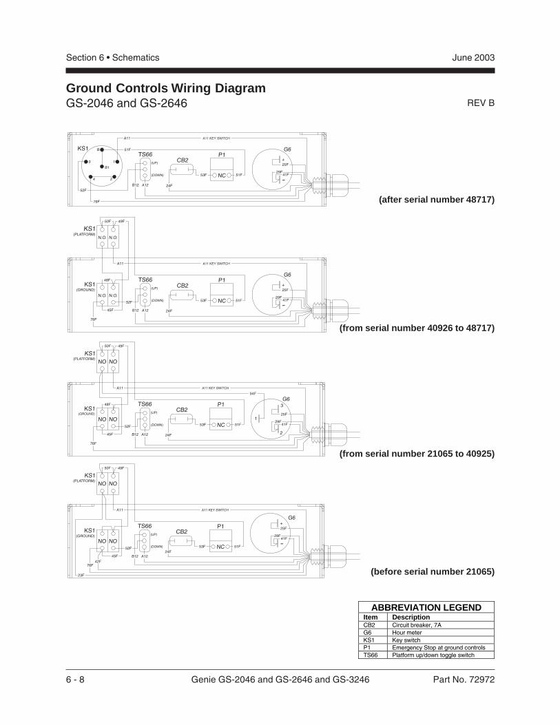
6 - 8 Genie GS-2046 and GS-2646 and GS-3246 Part No. 72972
Section 6 • Schematics June 2003
REV B
Ground Controls Wiring DiagramGS-2046 and GS-2646
(after serial number 48717)
(from serial number 40926 to 48717)
(from serial number 21065 to 40925)
(before serial number 21065)
-
G6
+
NC
P1
N.O.N.O.
TS66CB2
N.O. N.O.
KS1(PLATFORM)
KS1(GROUND) 25F
29F41F
24FA12
(UP)
B12
(DOWN)
76F
53F 51F
45F
50F 49F
48F
A11
52F
A11 KEY SWITCH
G6
NC
P1
NONO
TS66CB2
NO NO
KS1(PLATFORM)
KS1(GROUND) 25F
3
2
129F
41F
24FA12
(UP)
B12
(DOWN)
76F
53F 51F
54F
45F
50F 49F
48F
A11
52F
A11 KEY SWITCH
NC
P1
NONO
TS66CB2
NO NO
KS1(PLATFORM)
KS1(GROUND)
A12
(UP)
B12
(DOWN)
76F
-
G6+25F
29F41F
53F 51F
45F
50F 49F
23F
A11
52F
A11 KEY SWITCH
42F
24F
-
G6
+
NC
P1TS66CB2
25F
29F41F
24FA12
(UP)
B12
(DOWN) 53F 51F
A11 KEY SWITCH
KS1 51F
76F
A11
B
B1
3 1
4 2
52F
ABBREVIATION LEGENDItem DescriptionCB2 Circuit breaker, 7AG6 Hour meterKS1 Key switchP1 Emergency Stop at ground controlsTS66 Platform up/down toggle switch
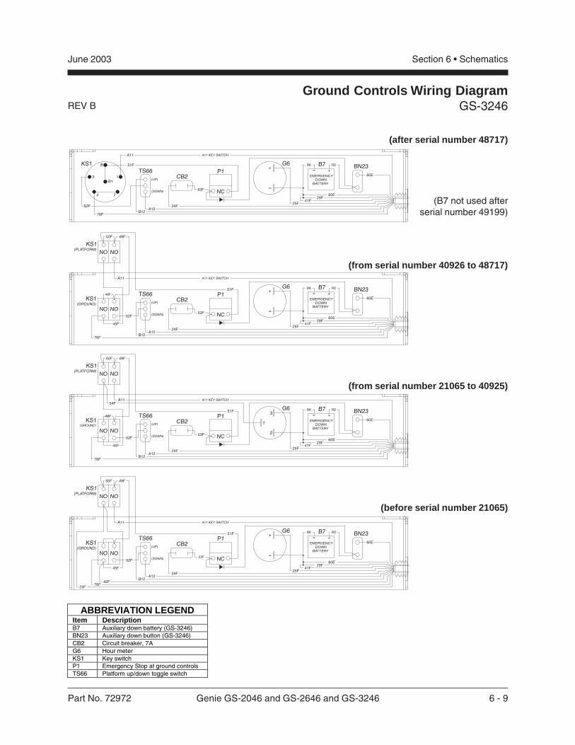
Part No. 72972 Genie GS-2046 and GS-2646 and GS-3246 6 - 9
Section 6 • SchematicsJune 2003
REV B
Ground Controls Wiring DiagramGS-3246
NC
P1
NONO
TS66BN23
CB2
NO NO
KS1(PLATFORM)
KS1(GROUND) (UP)
(DOWN)
G6
-
+51F
24FA12
B1276F
45F
50F 49F
48F
A11
52F
A11 KEY SWITCH
EMERGENCYDOWN
BATTERY
- +BK RD
60E
B7
53F
25F
29F41F
60E
NC
P1
NONO
TS66BN23
CB2
NO NO
KS1(PLATFORM)
KS1(GROUND)
3
2
1(UP)
(DOWN)
G6
53F
51F
24FA12
B1276F
45F
50F 49F
48F
A11
52F
A11 KEY SWITCH
EMERGENCYDOWN
BATTERY
- +BK RD
60E
B754F
25F
29F41F
60E
NC
P1
NONO
TS66BN23
CB2
NO NO
KS1(PLATFORM)
KS1(GROUND) (UP)
(DOWN)-
G6+
53F
51F
24FA12
B1242F
76F
45F
50F 49F
23F
A11
52F
A11 KEY SWITCH
EMERGENCYDOWN
BATTERY
- +BK RD
60E
B7
25F
29F41F
60E
NC
P1TS66BN23
CB2
KS1
(UP)
(DOWN)
G6
-
+51F
25F24F
A12B12
76F
A11
B
B13 1
4 2
52F
A11 KEY SWITCH
EMERGENCYDOWN
BATTERY
- +
29F41F
60E
BK RD
60E
B7
53F
(after serial number 48717)
(from serial number 40926 to 48717)
(from serial number 21065 to 40925)
(before serial number 21065)
(B7 not used afterserial number 49199)
ABBREVIATION LEGENDItem DescriptionB7 Auxiliary down battery (GS-3246)BN23 Auxiliary down button (GS-3246)CB2 Circuit breaker, 7AG6 Hour meterKS1 Key switchP1 Emergency Stop at ground controlsTS66 Platform up/down toggle switch
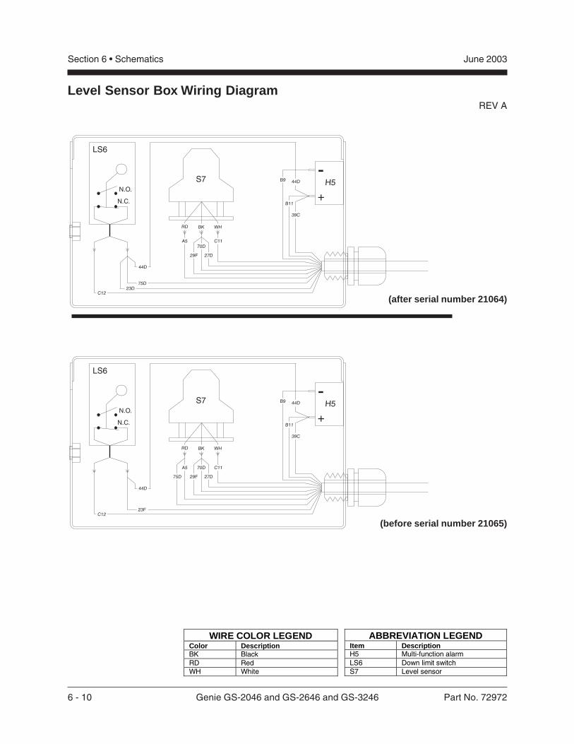
6 - 10 Genie GS-2046 and GS-2646 and GS-3246 Part No. 72972
Section 6 • Schematics June 2003
REV A
S7
S7
N.C.
N.C.
N.O.
N.O.
LS6
LS6
H5
H5
-
-
+
+
B11
B11
B9
B9
BK
BK
WH
WH
RD
RD
44D
44D
44D
44D
23F
75D23D
C12
C12
C11
C11
70D
70D
27D
27D
29F75D
29F
A5
A5
39C
39C
Level Sensor Box Wiring Diagram
(after serial number 21064)
(before serial number 21065)
ABBREVIATION LEGENDItem DescriptionH5 Multi-function alarmLS6 Down limit switchS7 Level sensor
WIRE COLOR LEGENDColor DescriptionBK BlackRD RedWH White
Part No. 72972 Genie GS-2046 and GS-2646 and GS-3246 6 - 11
Section 6 • SchematicsJune 2003
This page intentionally left blank.
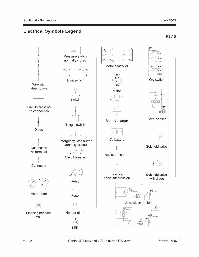
6 - 12 Genie GS-2046 and GS-2646 and GS-3246 Part No. 72972
Section 6 • Schematics June 2003
REV B
Electrical Symbols Legend
-
+
U9
CB2
13
2
FB
PLATFORMCONTROL
T
B
B
T
GROUNDCONTROL
KS1KEY SWITCH
A8
-MO
TO
RC
ON
TR
.E
NA
BL
E
N.C.H.O.N.C.
PS2 B+
3A2
T2
B- 1
B+
3A2
T2M-
B- 1
87A 85
8630
87
A1
D1
M5
N.O.
S7LEVEL
SENSOR
LEVEL SENSORCIRCUIT BOARD
JC1 JOYSTICK CONTROLLER
R155000 ohmPOTENTIOMETER SW6 STEER
LE
FT
RIG
HTSW5
FUNCTIONENABLE
JC1JOYSTICK
CONTROLLER
HALLGENERATOR
SW6STEER LEFT/ RIGHT
LE
FT
RIG
HTSW5
FUNCTIONENABLE
Wire withdescription
Circuits crossingno connection
Diode
Connectionno terminal
Connector
Hour meter
Flashing beaconsFB1
Pressure switchnormally closed
Limit switch
Switch
Toggle switch
Emergency Stop buttonNormally closed
Circuit breaker
Relay
Fuse
Horn or alarm
Motor controller
Motor
Battery charger
6V battery
Resistor, 75 ohm
Inductor,noise suppression
Key switch
Level sensor
Solenoid valve
Solenoid valvewith diode
Joystick controller
LED
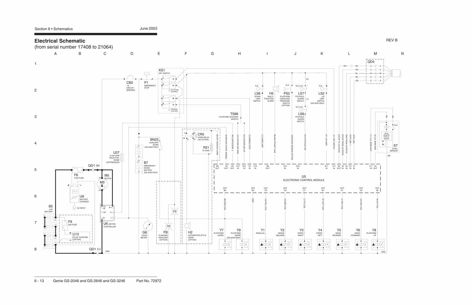
1
2
3
4
5
6
7
8
A B C D E F G H I J K L M N
Electrical Schematic(from serial number 17408 to 21064)
REV B
Section 6 • Schematics June 2003
6 - 13 Genie GS-2046 and GS-2646 and GS-3246 Part No. 72972
QD1 +( )
QD1 -( )
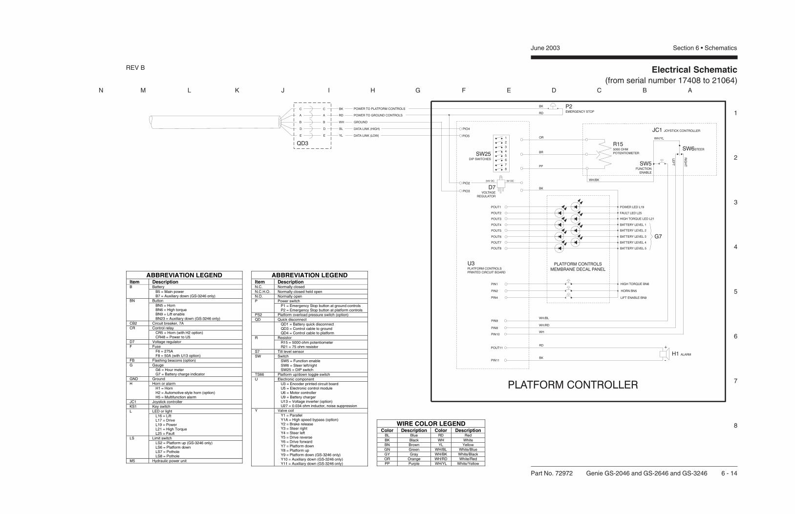
1
2
3
4
5
6
7
8
N M L K J I H G F E D C B A
Electrical Schematic(from serial number 17408 to 21064)
REV B
Part No. 72972 Genie GS-2046 and GS-2646 and GS-3246 6 - 14
June 2003 Section 6 • Schematics
ABBREVIATION LEGENDItem Description
BatteryB B5 = Main power B7 = Auxiliary down (GS-3246 only)ButtonBN BN5 = Horn BN6 = High torque BN9 = Lift enable BN23 = Auxiliary down (GS-3246 only)
CB2 Circuit breaker, 7AControl relayCR CR5 = Horn (with H2 option) CR48 = Power to U5
D7 Voltage regulatorFuseF F6 = 275A F8 = 50A (with U13 option)
FB Flashing beacons (option)GaugeG G6 = Hour meter G7 = Battery charge indicator
GND GroundHorn or alarmH H1 = Horn H2 = Automotive-style horn (option) H5 = Multifunction alarm
JC1 Joystick controllerKS1 Key switch
LED or lightL L16 = Lift L17 = Drive L19 = Power L21 = High Torque L25 = FaultLimit switchLS LS2 = Platform up (GS-3246 only) LS6 = Platform down LS7 = Pothole LS8 = Pothole
M5 Hydraulic power unit
ABBREVIATION LEGENDItem DescriptionN.C. Normally closedN.C.H.O. Normally closed held openN.O. Normally open
Power switchP P1 = Emergency Stop button at ground controls P2 = Emergency Stop button at platform controls
PS2 Platform overload pressure switch (option)QD Quick disconnect
QD1 = Battery quick disconnect QD3 = Control cable to ground QD4 = Control cable to platformResistorR R15 = 5000 ohm potentiometer R21 = 75 ohm resistor
S7 Tilt level sensorSwitchSW SW5 = Function enable SW6 = Steer left/right SW25 = DIP switch
TS66 Platform up/down toggle switchElectronic componentU U3 = Encoder printed circuit board U5 = Electronic control module U6 = Motor controller U9 = Battery charger U13 = Voltage inverter (option) U27 = 0.034 ohm inductor, noise suppressionValve coilY Y1 = Parallel Y1A = High speed bypass (option) Y2 = Brake release Y3 = Steer right Y4 = Steer left Y5 = Drive reverse Y6 = Drive forward Y7 = Platform down Y8 = Platform up Y9 = Platform down (GS-3246 only) Y10 = Auxiliary down (GS-3246 only) Y11 = Auxiliary down (GS-3246 only)
WIRE COLOR LEGENDColor Description Color Description
BL Blue RD RedBK Black WH WhiteBN Brown YL YellowGN Green WH/BL White/BlueGY Gray WH/BK White/BlackOR Orange WH/RD White/RedPP Purple WH/YL White/Yellow

Electrical Schematic (from serial number 17408 to 21064)
June 2003 Section 6 • Schematics

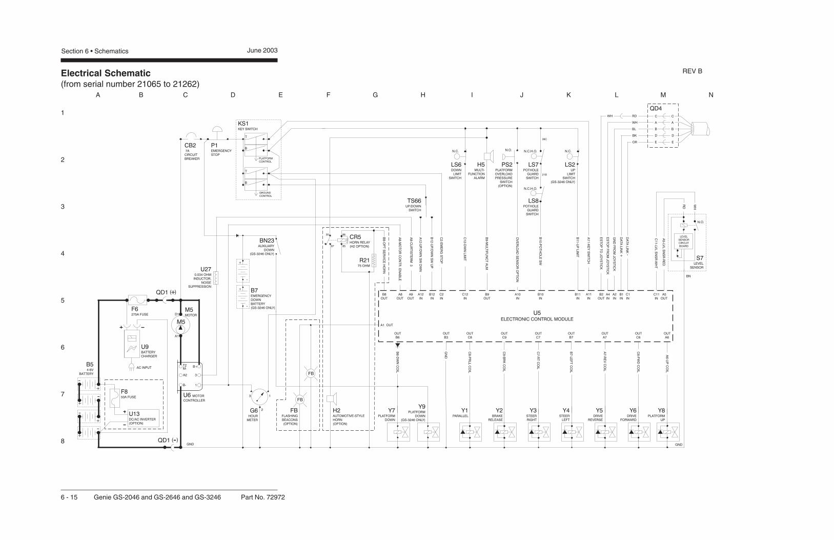
Electrical Schematic(from serial number 21065 to 21262)
1
2
3
4
5
6
7
8
A B C D E F G H I J K L M N
Section 6 • Schematics June 2003
6 - 15 Genie GS-2046 and GS-2646 and GS-3246 Part No. 72972
QD1 +( )
QD1 -( )
REV B
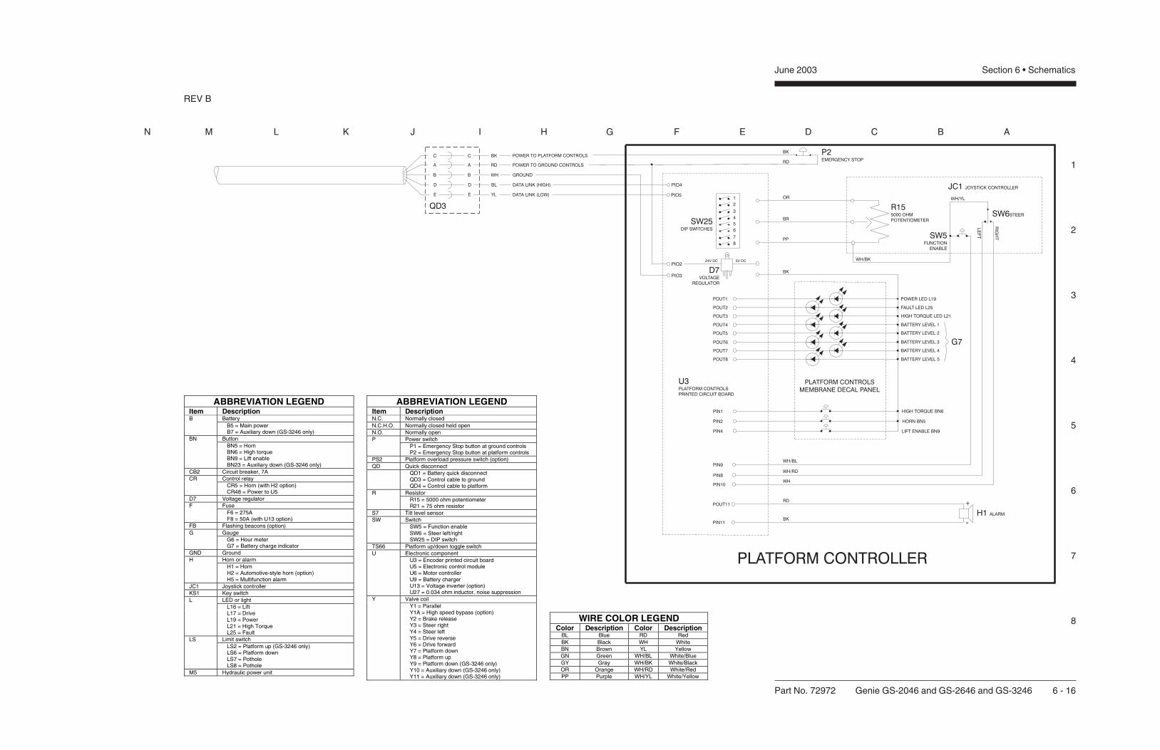
1
2
3
4
5
6
7
8
N M L K J I H G F E D C B A
Part No. 72972 Genie GS-2046 and GS-2646 and GS-3246 6 - 16
June 2003 Section 6 • Schematics
ABBREVIATION LEGENDItem Description
BatteryB B5 = Main power B7 = Auxiliary down (GS-3246 only)ButtonBN BN5 = Horn BN6 = High torque BN9 = Lift enable BN23 = Auxiliary down (GS-3246 only)
CB2 Circuit breaker, 7AControl relayCR CR5 = Horn (with H2 option) CR48 = Power to U5
D7 Voltage regulatorFuseF F6 = 275A F8 = 50A (with U13 option)
FB Flashing beacons (option)GaugeG G6 = Hour meter G7 = Battery charge indicator
GND GroundHorn or alarmH H1 = Horn H2 = Automotive-style horn (option) H5 = Multifunction alarm
JC1 Joystick controllerKS1 Key switch
LED or lightL L16 = Lift L17 = Drive L19 = Power L21 = High Torque L25 = FaultLimit switchLS LS2 = Platform up (GS-3246 only) LS6 = Platform down LS7 = Pothole LS8 = Pothole
M5 Hydraulic power unit
ABBREVIATION LEGENDItem DescriptionN.C. Normally closedN.C.H.O. Normally closed held openN.O. Normally open
Power switchP P1 = Emergency Stop button at ground controls P2 = Emergency Stop button at platform controls
PS2 Platform overload pressure switch (option)QD Quick disconnect
QD1 = Battery quick disconnect QD3 = Control cable to ground QD4 = Control cable to platformResistorR R15 = 5000 ohm potentiometer R21 = 75 ohm resistor
S7 Tilt level sensorSwitchSW SW5 = Function enable SW6 = Steer left/right SW25 = DIP switch
TS66 Platform up/down toggle switchElectronic componentU U3 = Encoder printed circuit board U5 = Electronic control module U6 = Motor controller U9 = Battery charger U13 = Voltage inverter (option) U27 = 0.034 ohm inductor, noise suppressionValve coilY Y1 = Parallel Y1A = High speed bypass (option) Y2 = Brake release Y3 = Steer right Y4 = Steer left Y5 = Drive reverse Y6 = Drive forward Y7 = Platform down Y8 = Platform up Y9 = Platform down (GS-3246 only) Y10 = Auxiliary down (GS-3246 only) Y11 = Auxiliary down (GS-3246 only)
WIRE COLOR LEGENDColor Description Color Description
BL Blue RD RedBK Black WH WhiteBN Brown YL YellowGN Green WH/BL White/BlueGY Gray WH/BK White/BlackOR Orange WH/RD White/RedPP Purple WH/YL White/Yellow
REV B
Electrical Schematic(from serial number 21065 to 21262)
June 2003 Section 6 • Schematics


Electrical Schematic(from serial number 21263 to 24438)
1
2
3
4
5
6
7
8
A B C D E F G H I J K L M N
Section 6 • Schematics June 2003
6 - 17 Genie GS-2046 and GS-2646 and GS-3246 Part No. 72972
QD1 +( )
QD1 -( )
REV B

Electrical Schematic(from serial number 21263 to 24438)
1
2
3
4
5
6
7
8
N M L K J I H G F E D C B A
Part No. 72972 Genie GS-2046 and GS-2646 and GS-3246 6 - 18
June 2003 Section 6 • Schematics
ABBREVIATION LEGENDItem Description
BatteryB B5 = Main power B7 = Auxiliary down (GS-3246 only)ButtonBN BN5 = Horn BN6 = High torque BN9 = Lift enable BN23 = Auxiliary down (GS-3246 only)
CB2 Circuit breaker, 7AControl relayCR CR5 = Horn (with H2 option) CR48 = Power to U5
D7 Voltage regulatorFuseF F6 = 275A F8 = 50A (with U13 option)
FB Flashing beacons (option)GaugeG G6 = Hour meter G7 = Battery charge indicator
GND GroundHorn or alarmH H1 = Horn H2 = Automotive-style horn (option) H5 = Multifunction alarm
JC1 Joystick controllerKS1 Key switch
LED or lightL L16 = Lift L17 = Drive L19 = Power L21 = High Torque L25 = FaultLimit switchLS LS2 = Platform up (GS-3246 only) LS6 = Platform down LS7 = Pothole LS8 = Pothole
M5 Hydraulic power unit
ABBREVIATION LEGENDItem DescriptionN.C. Normally closedN.C.H.O. Normally closed held openN.O. Normally open
Power switchP P1 = Emergency Stop button at ground controls P2 = Emergency Stop button at platform controls
PS2 Platform overload pressure switch (option)QD Quick disconnect
QD1 = Battery quick disconnect QD3 = Control cable to ground QD4 = Control cable to platformResistorR R15 = 5000 ohm potentiometer R21 = 75 ohm resistor
S7 Tilt level sensorSwitchSW SW5 = Function enable SW6 = Steer left/right SW25 = DIP switch
TS66 Platform up/down toggle switchElectronic componentU U3 = Encoder printed circuit board U5 = Electronic control module U6 = Motor controller U9 = Battery charger U13 = Voltage inverter (option) U27 = 0.034 ohm inductor, noise suppressionValve coilY Y1 = Parallel Y1A = High speed bypass (option) Y2 = Brake release Y3 = Steer right Y4 = Steer left Y5 = Drive reverse Y6 = Drive forward Y7 = Platform down Y8 = Platform up Y9 = Platform down (GS-3246 only) Y10 = Auxiliary down (GS-3246 only) Y11 = Auxiliary down (GS-3246 only)
WIRE COLOR LEGENDColor Description Color Description
BL Blue RD RedBK Black WH WhiteBN Brown YL YellowGN Green WH/BL White/BlueGY Gray WH/BK White/BlackOR Orange WH/RD White/RedPP Purple WH/YL White/Yellow
REV B

Electrical Schematic(from serial number 21263 to 24438)
June 2003 Section 6 • Schematics
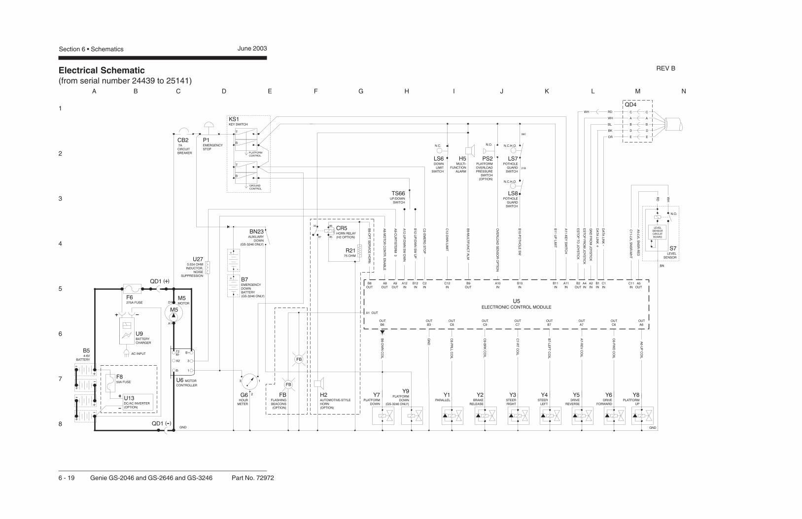
Electrical Schematic(from serial number 24439 to 25141)
1
2
3
4
5
6
7
8
A B C D E F G H I J K L M N
Section 6 • Schematics June 2003
6 - 19 Genie GS-2046 and GS-2646 and GS-3246 Part No. 72972
QD1 +( )
QD1 -( )
REV B

Electrical Schematic(from serial number 24439 to 25141)
1
2
3
4
5
6
7
8
N M L K J I H G F E D C B A
Part No. 72972 Genie GS-2046 and GS-2646 and GS-3246 6 - 20
June 2003 Section 6 • Schematics
ABBREVIATION LEGENDItem Description
BatteryB B5 = Main power B7 = Auxiliary down (GS-3246 only)ButtonBN BN5 = Horn BN6 = High torque BN9 = Lift enable BN23 = Auxiliary down (GS-3246 only)
CB2 Circuit breaker, 7AControl relayCR CR5 = Horn (with H2 option) CR48 = Power to U5
D7 Voltage regulatorFuseF F6 = 275A F8 = 50A (with U13 option)
FB Flashing beacons (option)GaugeG G6 = Hour meter G7 = Battery charge indicator
GND GroundHorn or alarmH H1 = Horn H2 = Automotive-style horn (option) H5 = Multifunction alarm
JC1 Joystick controllerKS1 Key switch
LED or lightL L16 = Lift L17 = Drive L19 = Power L21 = High Torque L25 = FaultLimit switchLS LS2 = Platform up (GS-3246 only) LS6 = Platform down LS7 = Pothole LS8 = Pothole
M5 Hydraulic power unit
ABBREVIATION LEGENDItem DescriptionN.C. Normally closedN.C.H.O. Normally closed held openN.O. Normally open
Power switchP P1 = Emergency Stop button at ground controls P2 = Emergency Stop button at platform controls
PS2 Platform overload pressure switch (option)QD Quick disconnect
QD1 = Battery quick disconnect QD3 = Control cable to ground QD4 = Control cable to platformResistorR R15 = 5000 ohm potentiometer R21 = 75 ohm resistor
S7 Tilt level sensorSwitchSW SW5 = Function enable SW6 = Steer left/right SW25 = DIP switch
TS66 Platform up/down toggle switchElectronic componentU U3 = Encoder printed circuit board U5 = Electronic control module U6 = Motor controller U9 = Battery charger U13 = Voltage inverter (option) U27 = 0.034 ohm inductor, noise suppressionValve coilY Y1 = Parallel Y1A = High speed bypass (option) Y2 = Brake release Y3 = Steer right Y4 = Steer left Y5 = Drive reverse Y6 = Drive forward Y7 = Platform down Y8 = Platform up Y9 = Platform down (GS-3246 only) Y10 = Auxiliary down (GS-3246 only) Y11 = Auxiliary down (GS-3246 only)
WIRE COLOR LEGENDColor Description Color Description
BL Blue RD RedBK Black WH WhiteBN Brown YL YellowGN Green WH/BL White/BlueGY Gray WH/BK White/BlackOR Orange WH/RD White/RedPP Purple WH/YL White/Yellow
REV B

Electrical Schematic(from serial number 24439 to 25141)
June 2003 Section 6 • Schematics

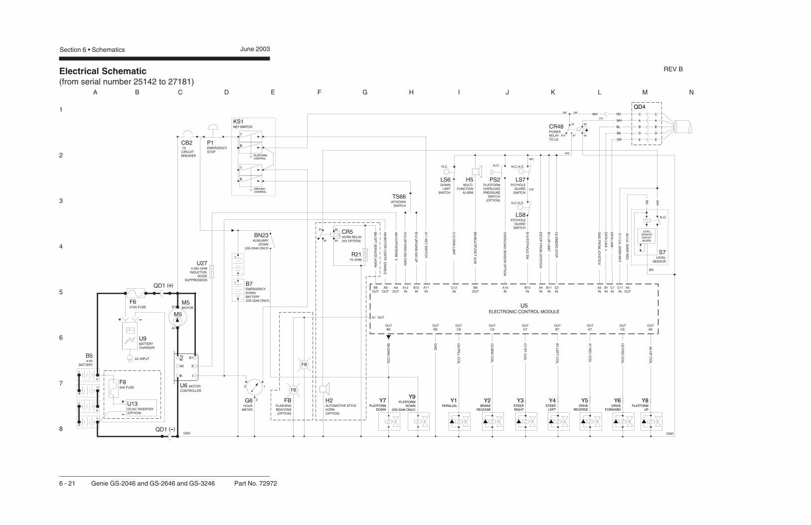
Electrical Schematic(from serial number 25142 to 27181)
1
2
3
4
5
6
7
8
A B C D E F G H I J K L M N
Section 6 • Schematics June 2003
6 - 21 Genie GS-2046 and GS-2646 and GS-3246 Part No. 72972
QD1 +( )
QD1 -( )
REV B

Electrical Schematic(from serial number 25142 to 27181)
1
2
3
4
5
6
7
8
N M L K J I H G F E D C B A
Part No. 72972 Genie GS-2046 and GS-2646 and GS-3246 6 - 22
June 2003 Section 6 • Schematics
ABBREVIATION LEGENDItem Description
BatteryB B5 = Main power B7 = Auxiliary down (GS-3246 only)ButtonBN BN5 = Horn BN6 = High torque BN9 = Lift enable BN23 = Auxiliary down (GS-3246 only)
CB2 Circuit breaker, 7AControl relayCR CR5 = Horn (with H2 option) CR48 = Power to U5
D7 Voltage regulatorFuseF F6 = 275A F8 = 50A (with U13 option)
FB Flashing beacons (option)GaugeG G6 = Hour meter G7 = Battery charge indicator
GND GroundHorn or alarmH H1 = Horn H2 = Automotive-style horn (option) H5 = Multifunction alarm
JC1 Joystick controllerKS1 Key switch
LED or lightL L16 = Lift L17 = Drive L19 = Power L21 = High Torque L25 = FaultLimit switchLS LS2 = Platform up (GS-3246 only) LS6 = Platform down LS7 = Pothole LS8 = Pothole
M5 Hydraulic power unit
ABBREVIATION LEGENDItem DescriptionN.C. Normally closedN.C.H.O. Normally closed held openN.O. Normally open
Power switchP P1 = Emergency Stop button at ground controls P2 = Emergency Stop button at platform controls
PS2 Platform overload pressure switch (option)QD Quick disconnect
QD1 = Battery quick disconnect QD3 = Control cable to ground QD4 = Control cable to platformResistorR R15 = 5000 ohm potentiometer R21 = 75 ohm resistor
S7 Tilt level sensorSwitchSW SW5 = Function enable SW6 = Steer left/right SW25 = DIP switch
TS66 Platform up/down toggle switchElectronic componentU U3 = Encoder printed circuit board U5 = Electronic control module U6 = Motor controller U9 = Battery charger U13 = Voltage inverter (option) U27 = 0.034 ohm inductor, noise suppressionValve coilY Y1 = Parallel Y1A = High speed bypass (option) Y2 = Brake release Y3 = Steer right Y4 = Steer left Y5 = Drive reverse Y6 = Drive forward Y7 = Platform down Y8 = Platform up Y9 = Platform down (GS-3246 only) Y10 = Auxiliary down (GS-3246 only) Y11 = Auxiliary down (GS-3246 only)
WIRE COLOR LEGENDColor Description Color Description
BL Blue RD RedBK Black WH WhiteBN Brown YL YellowGN Green WH/BL White/BlueGY Gray WH/BK White/BlackOR Orange WH/RD White/RedPP Purple WH/YL White/Yellow
REV B

Electrical Schematic(from serial number 25142 to 27181)
June 2003 Section 6 • Schematics

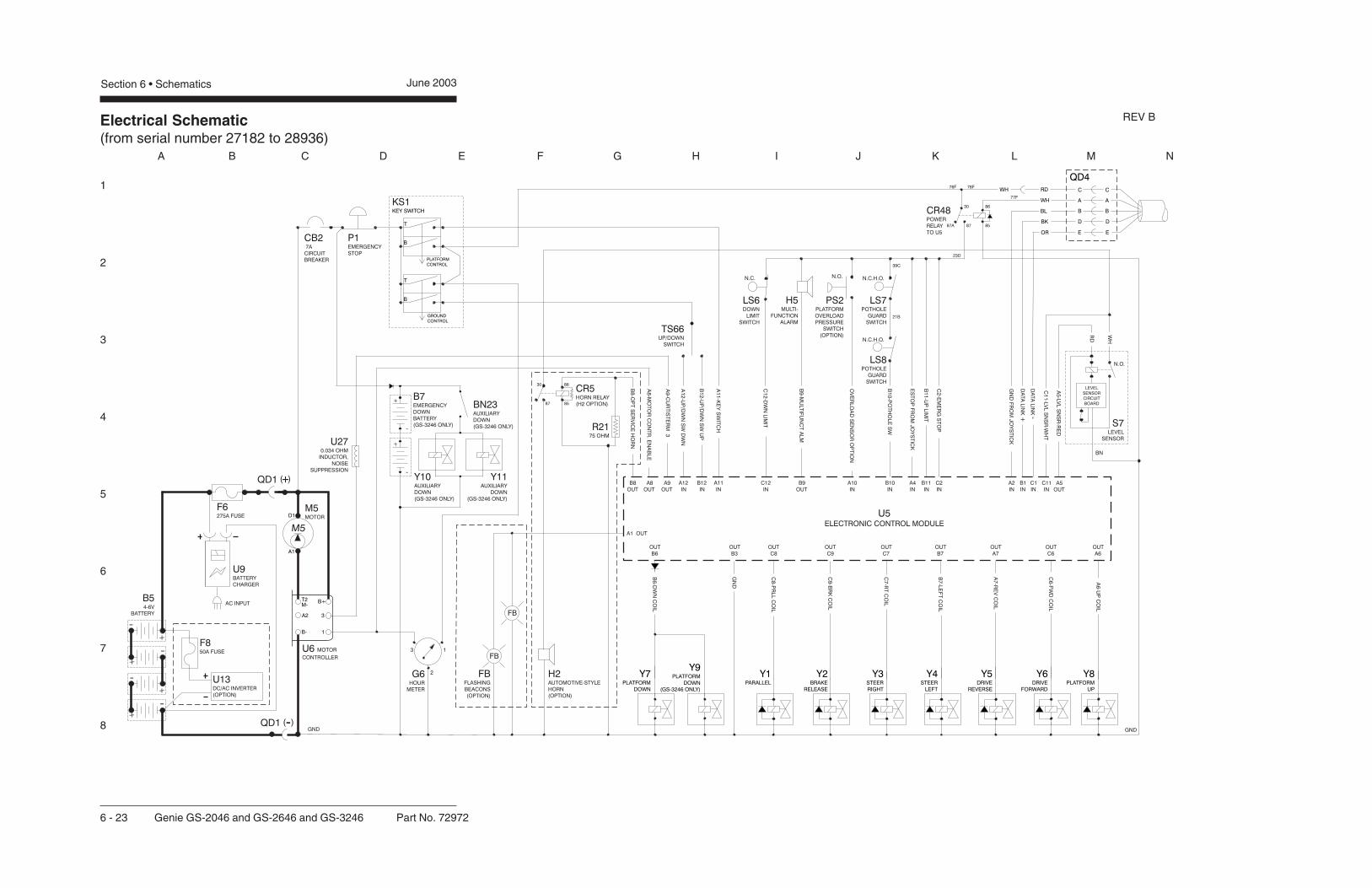
Electrical Schematic(from serial number 27182 to 28936)
1
2
3
4
5
6
7
8
A B C D E F G H I J K L M N
Section 6 • Schematics June 2003
6 - 23 Genie GS-2046 and GS-2646 and GS-3246 Part No. 72972
QD1 +( )
QD1 -( )
REV B

Electrical Schematic(from serial number 27182 to 28936)
1
2
3
4
5
6
7
8
N M L K J I H G F E D C B A
Part No. 72972 Genie GS-2046 and GS-2646 and GS-3246 6 - 24
June 2003 Section 6 • Schematics
ABBREVIATION LEGENDItem Description
BatteryB B5 = Main power B7 = Auxiliary down (GS-3246 only)ButtonBN BN5 = Horn BN6 = High torque BN9 = Lift enable BN23 = Auxiliary down (GS-3246 only)
CB2 Circuit breaker, 7AControl relayCR CR5 = Horn (with H2 option) CR48 = Power to U5
D7 Voltage regulatorFuseF F6 = 275A F8 = 50A (with U13 option)
FB Flashing beacons (option)GaugeG G6 = Hour meter G7 = Battery charge indicator
GND GroundHorn or alarmH H1 = Horn H2 = Automotive-style horn (option) H5 = Multifunction alarm
JC1 Joystick controllerKS1 Key switch
LED or lightL L16 = Lift L17 = Drive L19 = Power L21 = High Torque L25 = FaultLimit switchLS LS2 = Platform up (GS-3246 only) LS6 = Platform down LS7 = Pothole LS8 = Pothole
M5 Hydraulic power unit
ABBREVIATION LEGENDItem DescriptionN.C. Normally closedN.C.H.O. Normally closed held openN.O. Normally open
Power switchP P1 = Emergency Stop button at ground controls P2 = Emergency Stop button at platform controls
PS2 Platform overload pressure switch (option)QD Quick disconnect
QD1 = Battery quick disconnect QD3 = Control cable to ground QD4 = Control cable to platformResistorR R15 = 5000 ohm potentiometer R21 = 75 ohm resistor
S7 Tilt level sensorSwitchSW SW5 = Function enable SW6 = Steer left/right SW25 = DIP switch
TS66 Platform up/down toggle switchElectronic componentU U3 = Encoder printed circuit board U5 = Electronic control module U6 = Motor controller U9 = Battery charger U13 = Voltage inverter (option) U27 = 0.034 ohm inductor, noise suppressionValve coilY Y1 = Parallel Y1A = High speed bypass (option) Y2 = Brake release Y3 = Steer right Y4 = Steer left Y5 = Drive reverse Y6 = Drive forward Y7 = Platform down Y8 = Platform up Y9 = Platform down (GS-3246 only) Y10 = Auxiliary down (GS-3246 only) Y11 = Auxiliary down (GS-3246 only)
WIRE COLOR LEGENDColor Description Color Description
BL Blue RD RedBK Black WH WhiteBN Brown YL YellowGN Green WH/BL White/BlueGY Gray WH/BK White/BlackOR Orange WH/RD White/RedPP Purple WH/YL White/Yellow
REV B
Electrical Schematic(from serial number 27182 to 28936)
June 2003 Section 6 • Schematics

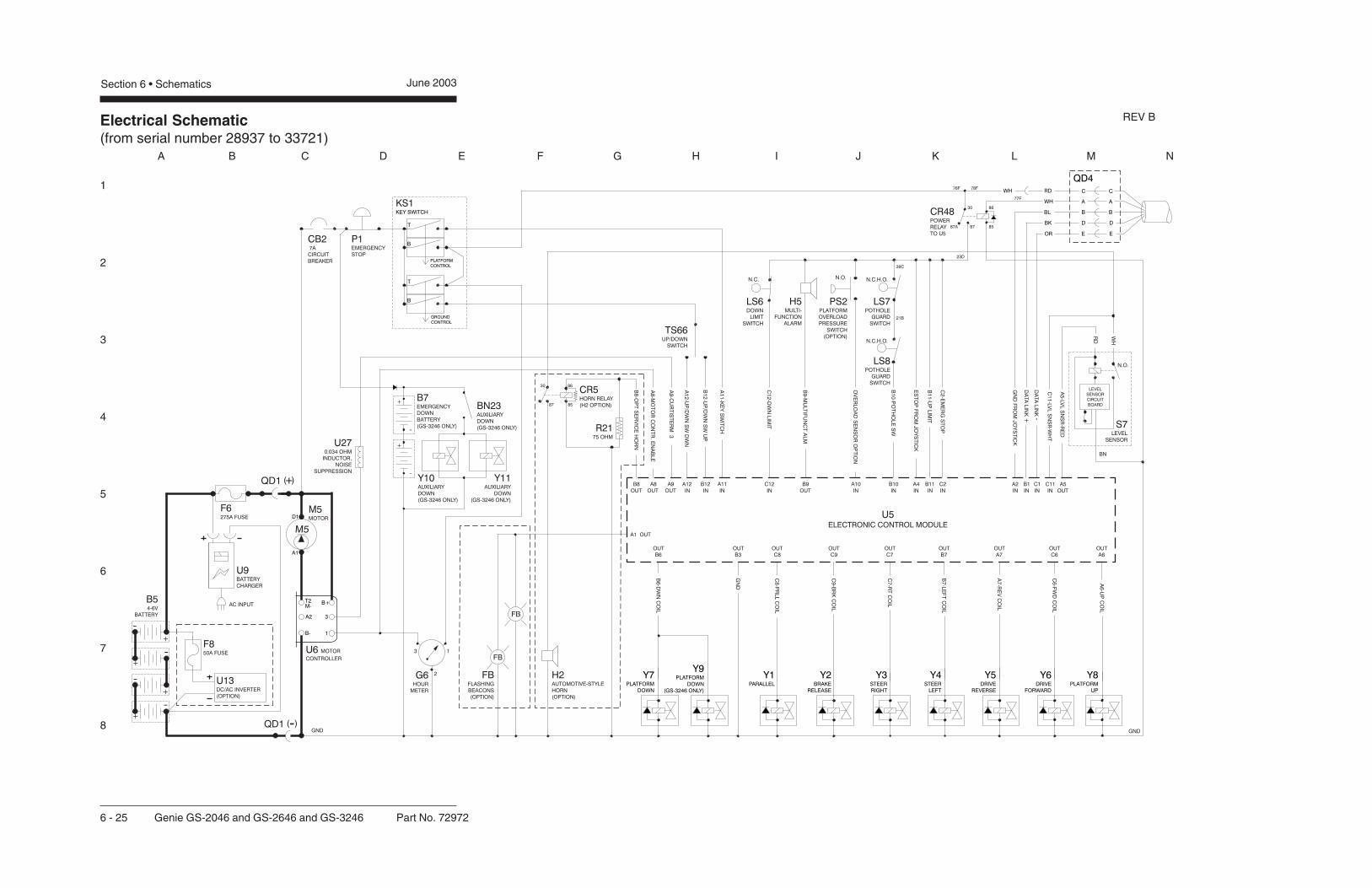
Electrical Schematic(from serial number 28937 to 33721)
1
2
3
4
5
6
7
8
A B C D E F G H I J K L M N
Section 6 • Schematics June 2003
6 - 25 Genie GS-2046 and GS-2646 and GS-3246 Part No. 72972
QD1 +( )
QD1 -( )
REV B
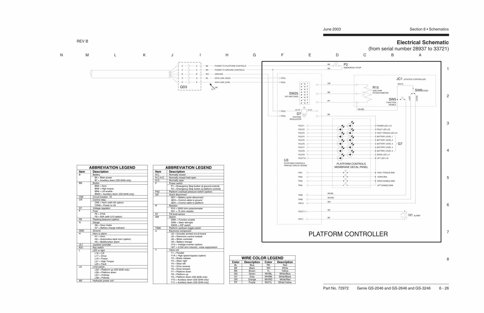
Electrical Schematic(from serial number 28937 to 33721)
1
2
3
4
5
6
7
8
N M L K J I H G F E D C B A
Part No. 72972 Genie GS-2046 and GS-2646 and GS-3246 6 - 26
June 2003 Section 6 • Schematics
ABBREVIATION LEGENDItem Description
BatteryB B5 = Main power B7 = Auxiliary down (GS-3246 only)ButtonBN BN5 = Horn BN6 = High torque BN9 = Lift enable BN23 = Auxiliary down (GS-3246 only)
CB2 Circuit breaker, 7AControl relayCR CR5 = Horn (with H2 option) CR48 = Power to U5
D7 Voltage regulatorFuseF F6 = 275A F8 = 50A (with U13 option)
FB Flashing beacons (option)GaugeG G6 = Hour meter G7 = Battery charge indicator
GND GroundHorn or alarmH H1 = Horn H2 = Automotive-style horn (option) H5 = Multifunction alarm
JC1 Joystick controllerKS1 Key switch
LED or lightL L16 = Lift L17 = Drive L19 = Power L21 = High Torque L25 = FaultLimit switchLS LS2 = Platform up (GS-3246 only) LS6 = Platform down LS7 = Pothole LS8 = Pothole
M5 Hydraulic power unit
ABBREVIATION LEGENDItem DescriptionN.C. Normally closedN.C.H.O. Normally closed held openN.O. Normally open
Power switchP P1 = Emergency Stop button at ground controls P2 = Emergency Stop button at platform controls
PS2 Platform overload pressure switch (option)QD Quick disconnect
QD1 = Battery quick disconnect QD3 = Control cable to ground QD4 = Control cable to platformResistorR R15 = 5000 ohm potentiometer R21 = 75 ohm resistor
S7 Tilt level sensorSwitchSW SW5 = Function enable SW6 = Steer left/right SW25 = DIP switch
TS66 Platform up/down toggle switchElectronic componentU U3 = Encoder printed circuit board U5 = Electronic control module U6 = Motor controller U9 = Battery charger U13 = Voltage inverter (option) U27 = 0.034 ohm inductor, noise suppressionValve coilY Y1 = Parallel Y1A = High speed bypass (option) Y2 = Brake release Y3 = Steer right Y4 = Steer left Y5 = Drive reverse Y6 = Drive forward Y7 = Platform down Y8 = Platform up Y9 = Platform down (GS-3246 only) Y10 = Auxiliary down (GS-3246 only) Y11 = Auxiliary down (GS-3246 only)
WIRE COLOR LEGENDColor Description Color Description
BL Blue RD RedBK Black WH WhiteBN Brown YL YellowGN Green WH/BL White/BlueGY Gray WH/BK White/BlackOR Orange WH/RD White/RedPP Purple WH/YL White/Yellow
REV B
Electrical Schematic(from serial number 28937 to 33721)
June 2003 Section 6 • Schematics

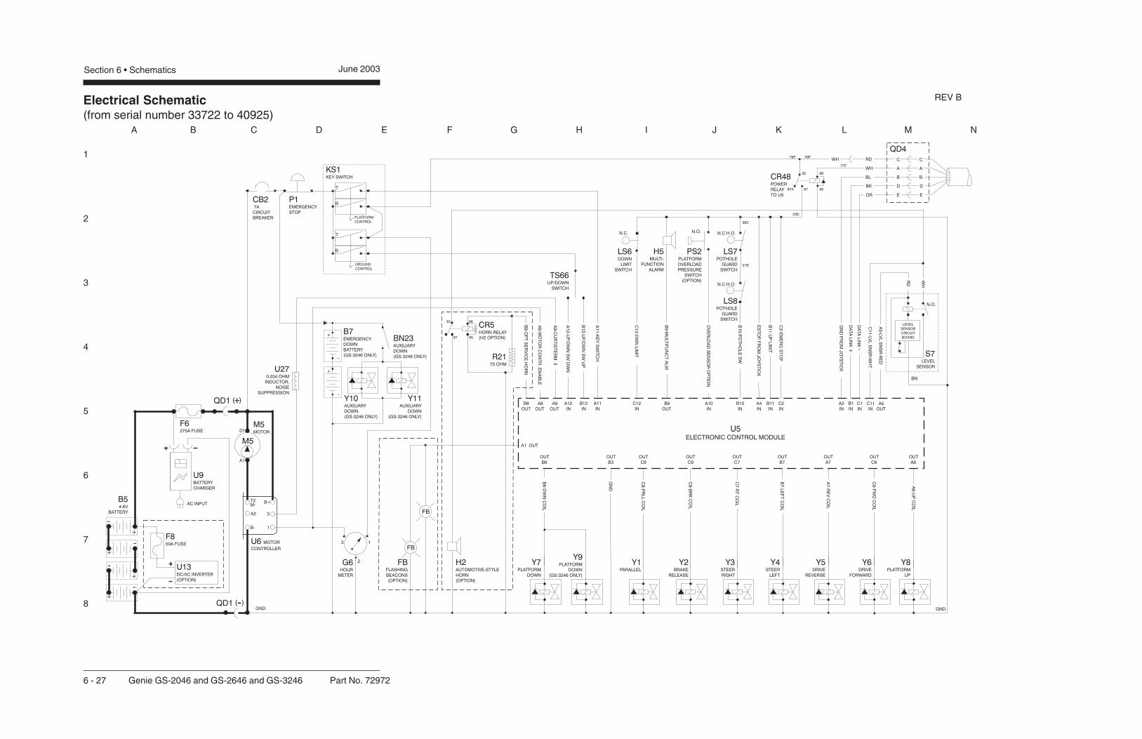
Electrical Schematic(from serial number 33722 to 40925)
1
2
3
4
5
6
7
8
A B C D E F G H I J K L M N
Section 6 • Schematics June 2003
6 - 27 Genie GS-2046 and GS-2646 and GS-3246 Part No. 72972
QD1 +( )
QD1 -( )
REV B

Electrical Schematic(from serial number 33722 to 40925)
1
2
3
4
5
6
7
8
N M L K J I H G F E D C B A
Part No. 72972 Genie GS-2046 and GS-2646 and GS-3246 6 - 28
June 2003 Section 6 • Schematics
ABBREVIATION LEGENDItem Description
BatteryB B5 = Main power B7 = Auxiliary down (GS-3246 only)ButtonBN BN5 = Horn BN6 = High torque BN9 = Lift enable BN23 = Auxiliary down (GS-3246 only)
CB2 Circuit breaker, 7AControl relayCR CR5 = Horn (with H2 option) CR48 = Power to U5
D7 Voltage regulatorFuseF F6 = 275A F8 = 50A (with U13 option)
FB Flashing beacons (option)GaugeG G6 = Hour meter G7 = Battery charge indicator
GND GroundHorn or alarmH H1 = Horn H2 = Automotive-style horn (option) H5 = Multifunction alarm
JC1 Joystick controllerKS1 Key switch
LED or lightL L16 = Lift L17 = Drive L19 = Power L21 = High Torque L25 = FaultLimit switchLS LS2 = Platform up (GS-3246 only) LS6 = Platform down LS7 = Pothole LS8 = Pothole
M5 Hydraulic power unit
ABBREVIATION LEGENDItem DescriptionN.C. Normally closedN.C.H.O. Normally closed held openN.O. Normally open
Power switchP P1 = Emergency Stop button at ground controls P2 = Emergency Stop button at platform controls
PS2 Platform overload pressure switch (option)QD Quick disconnect
QD1 = Battery quick disconnect QD3 = Control cable to ground QD4 = Control cable to platformResistorR R15 = 5000 ohm potentiometer R21 = 75 ohm resistor
S7 Tilt level sensorSwitchSW SW5 = Function enable SW6 = Steer left/right SW25 = DIP switch
TS66 Platform up/down toggle switchElectronic componentU U3 = Encoder printed circuit board U5 = Electronic control module U6 = Motor controller U9 = Battery charger U13 = Voltage inverter (option) U27 = 0.034 ohm inductor, noise suppressionValve coilY Y1 = Parallel Y1A = High speed bypass (option) Y2 = Brake release Y3 = Steer right Y4 = Steer left Y5 = Drive reverse Y6 = Drive forward Y7 = Platform down Y8 = Platform up Y9 = Platform down (GS-3246 only) Y10 = Auxiliary down (GS-3246 only) Y11 = Auxiliary down (GS-3246 only)
WIRE COLOR LEGENDColor Description Color Description
BL Blue RD RedBK Black WH WhiteBN Brown YL YellowGN Green WH/BL White/BlueGY Gray WH/BK White/BlackOR Orange WH/RD White/RedPP Purple WH/YL White/Yellow
REV B

Electrical Schematic(from serial number 33722 to 40925)
June 2003 Section 6 • Schematics

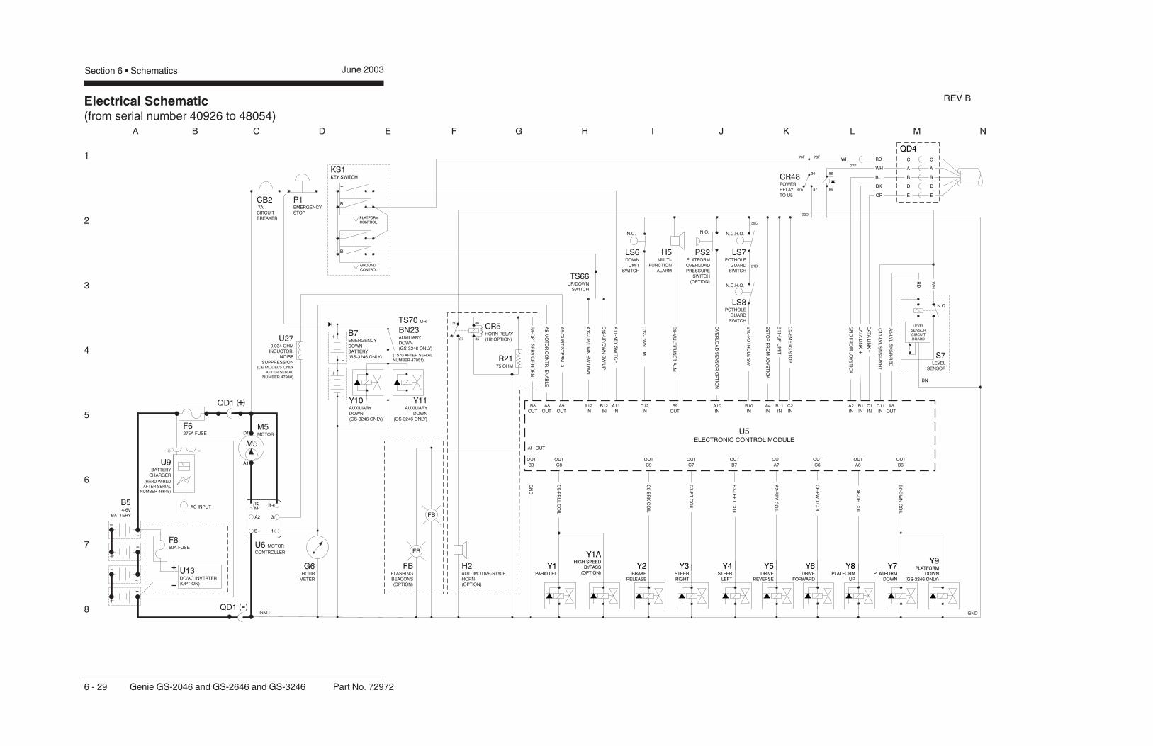
Electrical Schematic(from serial number 40926 to 48054)
1
2
3
4
5
6
7
8
A B C D E F G H I J K L M N
Section 6 • Schematics June 2003
6 - 29 Genie GS-2046 and GS-2646 and GS-3246 Part No. 72972
QD1 +( )
QD1 -( )
REV B

Electrical Schematic(from serial number 40926 to 48054)
1
2
3
4
5
6
7
8
N M L K J I H G F E D C B A
Part No. 72972 Genie GS-2046 and GS-2646 and GS-3246 6 - 30
June 2003 Section 6 • Schematics
ABBREVIATION LEGENDItem Description
BatteryB B5 = Main power B7 = Auxiliary down (GS-3246 only)ButtonBN BN5 = Horn BN6 = High torque BN9 = Lift enable BN23 = Auxiliary down (GS-3246 only)
CB2 Circuit breaker, 7AControl relayCR CR5 = Horn (with H2 option) CR48 = Power to U5
D7 Voltage regulatorFuseF F6 = 275A F8 = 50A (with U13 option)
FB Flashing beacons (option)GaugeG G6 = Hour meter G7 = Battery charge indicator
GND GroundHorn or alarmH H1 = Horn H2 = Automotive-style horn (option) H5 = Multifunction alarm
JC1 Joystick controllerKS1 Key switch
LED or lightL L16 = Lift L17 = Drive L19 = Power L21 = High Torque L25 = FaultLimit switchLS LS2 = Platform up (GS-3246 only) LS6 = Platform down LS7 = Pothole LS8 = Pothole
M5 Hydraulic power unit
ABBREVIATION LEGENDItem DescriptionN.C. Normally closedN.C.H.O. Normally closed held openN.O. Normally open
Power switchP P1 = Emergency Stop button at ground controls P2 = Emergency Stop button at platform controls
PS2 Platform overload pressure switch (option)QD Quick disconnect
QD1 = Battery quick disconnect QD3 = Control cable to ground QD4 = Control cable to platformResistorR R15 = 5000 ohm potentiometer R21 = 75 ohm resistor
S7 Tilt level sensorSwitchSW SW5 = Function enable SW6 = Steer left/right SW25 = DIP switch
TS66 Platform up/down toggle switchElectronic componentU U3 = Encoder printed circuit board U5 = Electronic control module U6 = Motor controller U9 = Battery charger U13 = Voltage inverter (option) U27 = 0.034 ohm inductor, noise suppressionValve coilY Y1 = Parallel Y1A = High speed bypass (option) Y2 = Brake release Y3 = Steer right Y4 = Steer left Y5 = Drive reverse Y6 = Drive forward Y7 = Platform down Y8 = Platform up Y9 = Platform down (GS-3246 only) Y10 = Auxiliary down (GS-3246 only) Y11 = Auxiliary down (GS-3246 only)
WIRE COLOR LEGENDColor Description Color Description
BL Blue RD RedBK Black WH WhiteBN Brown YL YellowGN Green WH/BL White/BlueGY Gray WH/BK White/BlackOR Orange WH/RD White/RedPP Purple WH/YL White/Yellow
REV B

Electrical Schematic(from serial number 40926 to 48054)
June 2003 Section 6 • Schematics

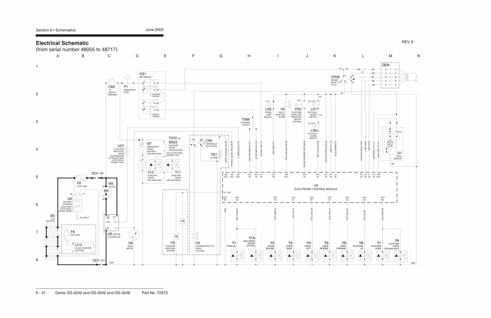
Electrical Schematic(from serial number 48055 to 48717)
1
2
3
4
5
6
7
8
A B C D E F G H I J K L M N
Section 6 • Schematics June 2003
6 - 31 Genie GS-2046 and GS-2646 and GS-3246 Part No. 72972
QD1 +( )
QD1 -( )
REV A

Electrical Schematic(from serial number 48055 to 48717)
1
2
3
4
5
6
7
8
N M L K J I H G F E D C B A
Part No. 72972 Genie GS-2046 and GS-2646 and GS-3246 6 - 32
June 2003 Section 6 • Schematics
ABBREVIATION LEGENDItem Description
BatteryB B5 = Main power B7 = Auxiliary down (GS-3246 only)ButtonBN BN5 = Horn BN6 = High torque BN9 = Lift enable BN23 = Auxiliary down (GS-3246 only)
CB2 Circuit breaker, 7AControl relayCR CR5 = Horn (with H2 option) CR48 = Power to U5
D7 Voltage regulatorFuseF F6 = 275A F8 = 50A (with U13 option)
FB Flashing beacons (option)GaugeG G6 = Hour meter G7 = Battery charge indicator
GND GroundHorn or alarmH H1 = Horn H2 = Automotive-style horn (option) H5 = Multifunction alarm
JC1 Joystick controllerKS1 Key switch
LED or lightL L16 = Lift L17 = Drive L19 = Power L21 = High Torque L25 = FaultLimit switchLS LS2 = Platform up (GS-3246 only) LS6 = Platform down LS7 = Pothole LS8 = Pothole
M5 Hydraulic power unit
ABBREVIATION LEGENDItem DescriptionN.C. Normally closedN.C.H.O. Normally closed held openN.O. Normally open
Power switchP P1 = Emergency Stop button at ground controls P2 = Emergency Stop button at platform controls
PS2 Platform overload pressure switch (option)QD Quick disconnect
QD1 = Battery quick disconnect QD3 = Control cable to ground QD4 = Control cable to platformResistorR R15 = 5000 ohm potentiometer R21 = 75 ohm resistor
S7 Tilt level sensorSwitchSW SW5 = Function enable SW6 = Steer left/right SW25 = DIP switch
TS66 Platform up/down toggle switchElectronic componentU U3 = Encoder printed circuit board U5 = Electronic control module U6 = Motor controller U9 = Battery charger U13 = Voltage inverter (option) U27 = 0.034 ohm inductor, noise suppressionValve coilY Y1 = Parallel Y1A = High speed bypass (option) Y2 = Brake release Y3 = Steer right Y4 = Steer left Y5 = Drive reverse Y6 = Drive forward Y7 = Platform down Y8 = Platform up Y9 = Platform down (GS-3246 only) Y10 = Auxiliary down (GS-3246 only) Y11 = Auxiliary down (GS-3246 only)
WIRE COLOR LEGENDColor Description Color Description
BL Blue RD RedBK Black WH WhiteBN Brown YL YellowGN Green WH/BL White/BlueGY Gray WH/BK White/BlackOR Orange WH/RD White/RedPP Purple WH/YL White/Yellow
REV A

Electrical Schematic(from serial number 48055 to 48717)
June 2003 Section 6 • Schematics
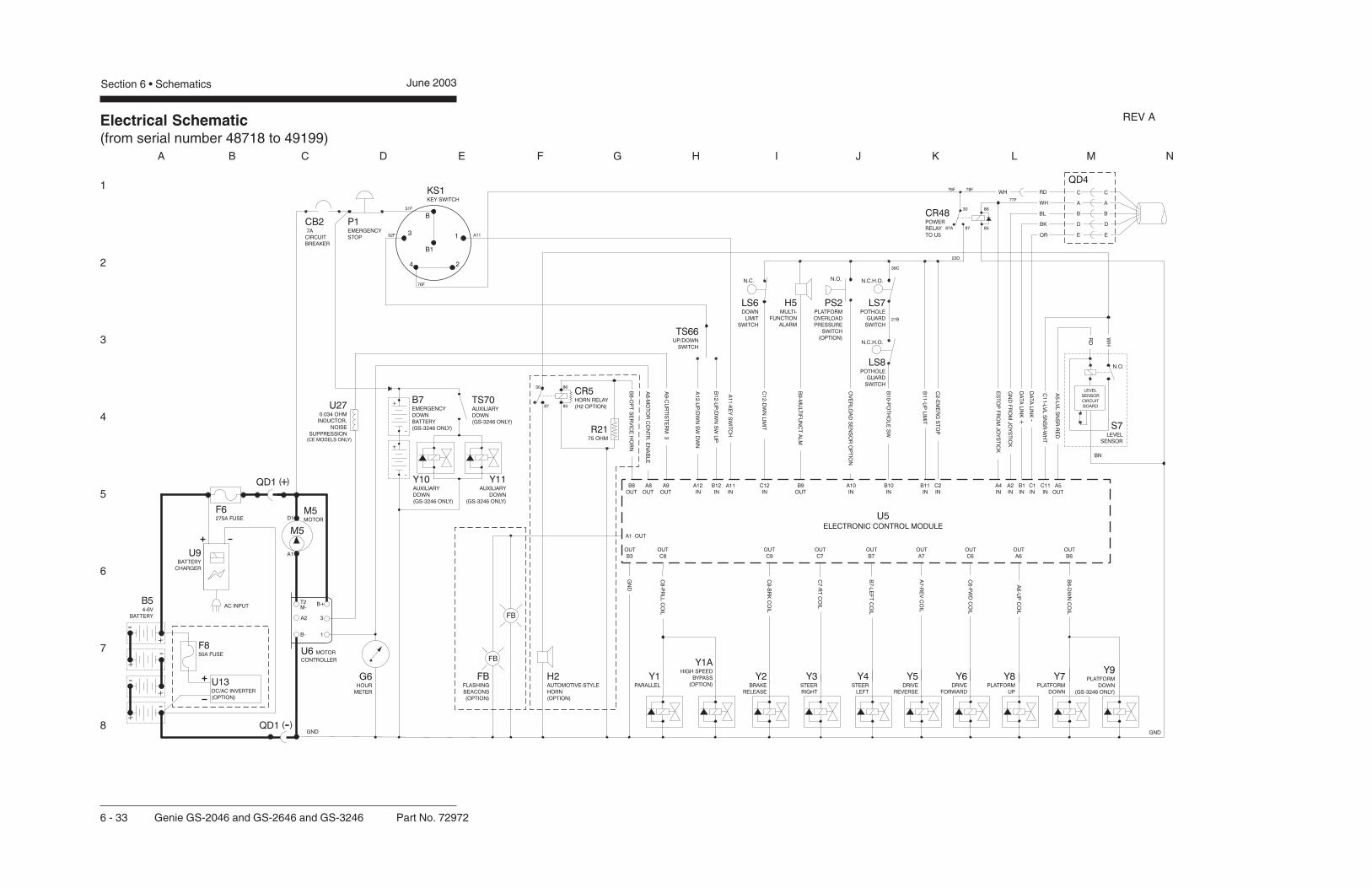
Electrical Schematic(from serial number 48718 to 49199)
1
2
3
4
5
6
7
8
A B C D E F G H I J K L M N
Section 6 • Schematics June 2003
6 - 33 Genie GS-2046 and GS-2646 and GS-3246 Part No. 72972
QD1 +( )
QD1 -( )
REV A

Electrical Schematic(from serial number 48718 to 49199)
1
2
3
4
5
6
7
8
N M L K J I H G F E D C B A
Part No. 72972 Genie GS-2046 and GS-2646 and GS-3246 6 - 34
June 2003 Section 6 • Schematics
ABBREVIATION LEGENDItem Description
BatteryB B5 = Main power B7 = Auxiliary down (GS-3246 only)ButtonBN BN5 = Horn BN6 = High torque BN9 = Lift enable BN23 = Auxiliary down (GS-3246 only)
CB2 Circuit breaker, 7AControl relayCR CR5 = Horn (with H2 option) CR48 = Power to U5
D7 Voltage regulatorFuseF F6 = 275A F8 = 50A (with U13 option)
FB Flashing beacons (option)GaugeG G6 = Hour meter G7 = Battery charge indicator
GND GroundHorn or alarmH H1 = Horn H2 = Automotive-style horn (option) H5 = Multifunction alarm
JC1 Joystick controllerKS1 Key switch
LED or lightL L16 = Lift L17 = Drive L19 = Power L21 = High Torque L25 = FaultLimit switchLS LS2 = Platform up (GS-3246 only) LS6 = Platform down LS7 = Pothole LS8 = Pothole
M5 Hydraulic power unit
ABBREVIATION LEGENDItem DescriptionN.C. Normally closedN.C.H.O. Normally closed held openN.O. Normally open
Power switchP P1 = Emergency Stop button at ground controls P2 = Emergency Stop button at platform controls
PS2 Platform overload pressure switch (option)QD Quick disconnect
QD1 = Battery quick disconnect QD3 = Control cable to ground QD4 = Control cable to platformResistorR R15 = 5000 ohm potentiometer R21 = 75 ohm resistor
S7 Tilt level sensorSwitchSW SW5 = Function enable SW6 = Steer left/right SW25 = DIP switch
TS66 Platform up/down toggle switchElectronic componentU U3 = Encoder printed circuit board U5 = Electronic control module U6 = Motor controller U9 = Battery charger U13 = Voltage inverter (option) U27 = 0.034 ohm inductor, noise suppressionValve coilY Y1 = Parallel Y1A = High speed bypass (option) Y2 = Brake release Y3 = Steer right Y4 = Steer left Y5 = Drive reverse Y6 = Drive forward Y7 = Platform down Y8 = Platform up Y9 = Platform down (GS-3246 only) Y10 = Auxiliary down (GS-3246 only) Y11 = Auxiliary down (GS-3246 only)
WIRE COLOR LEGENDColor Description Color Description
BL Blue RD RedBK Black WH WhiteBN Brown YL YellowGN Green WH/BL White/BlueGY Gray WH/BK White/BlackOR Orange WH/RD White/RedPP Purple WH/YL White/Yellow
REV A

Electrical Schematic(from serial number 48718 to 49199)
June 2003 Section 6 • Schematics

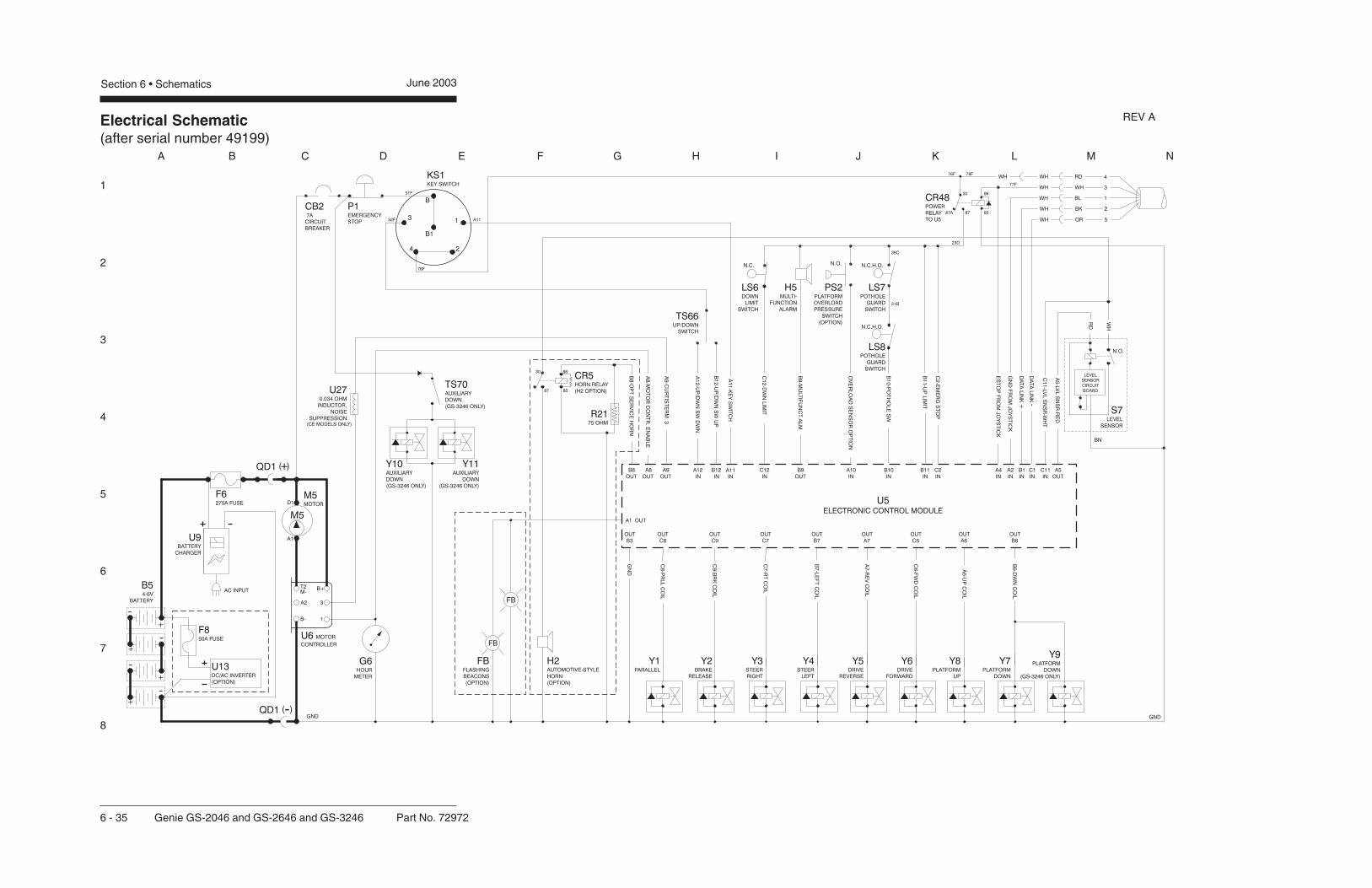
Electrical Schematic(after serial number 49199)
1
2
3
4
5
6
7
8
A B C D E F G H I J K L M N
Section 6 • Schematics June 2003
6 - 35 Genie GS-2046 and GS-2646 and GS-3246 Part No. 72972
QD1 +( )
QD1 -( )
REV A
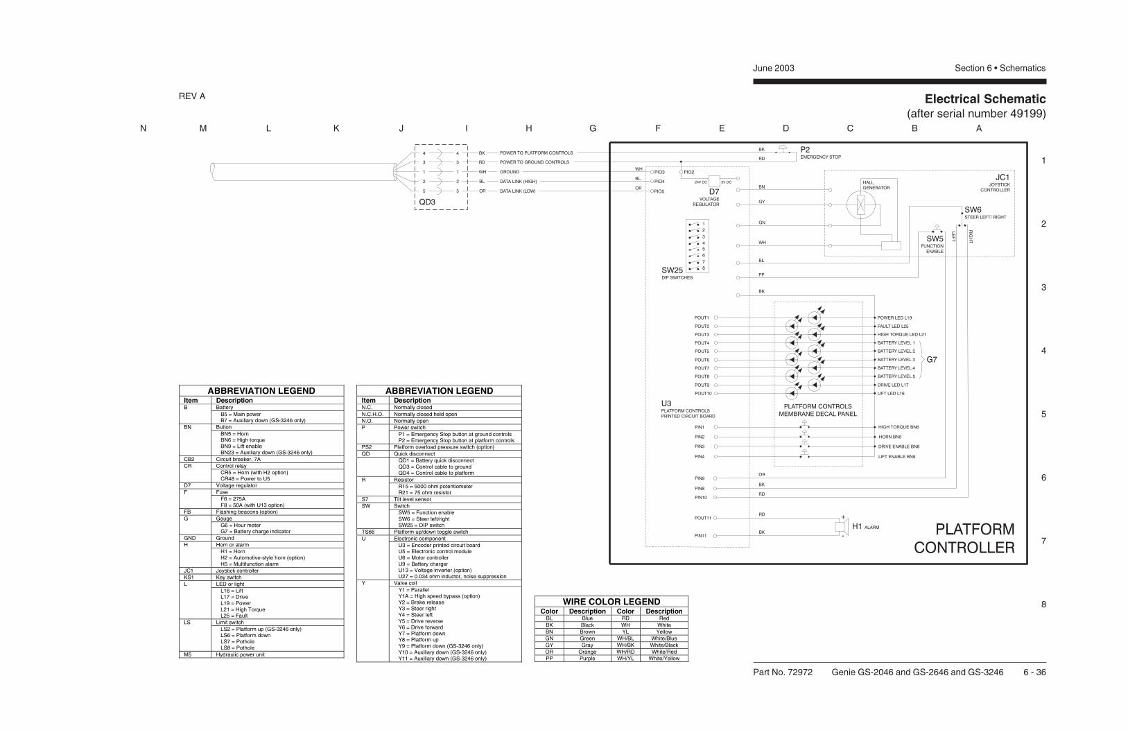
Electrical Schematic(after serial number 49199)
1
2
3
4
5
6
7
8
N M L K J I H G F E D C B A
Part No. 72972 Genie GS-2046 and GS-2646 and GS-3246 6 - 36
June 2003 Section 6 • Schematics
ABBREVIATION LEGENDItem Description
BatteryB B5 = Main power B7 = Auxiliary down (GS-3246 only)ButtonBN BN5 = Horn BN6 = High torque BN9 = Lift enable BN23 = Auxiliary down (GS-3246 only)
CB2 Circuit breaker, 7AControl relayCR CR5 = Horn (with H2 option) CR48 = Power to U5
D7 Voltage regulatorFuseF F6 = 275A F8 = 50A (with U13 option)
FB Flashing beacons (option)GaugeG G6 = Hour meter G7 = Battery charge indicator
GND GroundHorn or alarmH H1 = Horn H2 = Automotive-style horn (option) H5 = Multifunction alarm
JC1 Joystick controllerKS1 Key switch
LED or lightL L16 = Lift L17 = Drive L19 = Power L21 = High Torque L25 = FaultLimit switchLS LS2 = Platform up (GS-3246 only) LS6 = Platform down LS7 = Pothole LS8 = Pothole
M5 Hydraulic power unit
ABBREVIATION LEGENDItem DescriptionN.C. Normally closedN.C.H.O. Normally closed held openN.O. Normally open
Power switchP P1 = Emergency Stop button at ground controls P2 = Emergency Stop button at platform controls
PS2 Platform overload pressure switch (option)QD Quick disconnect
QD1 = Battery quick disconnect QD3 = Control cable to ground QD4 = Control cable to platformResistorR R15 = 5000 ohm potentiometer R21 = 75 ohm resistor
S7 Tilt level sensorSwitchSW SW5 = Function enable SW6 = Steer left/right SW25 = DIP switch
TS66 Platform up/down toggle switchElectronic componentU U3 = Encoder printed circuit board U5 = Electronic control module U6 = Motor controller U9 = Battery charger U13 = Voltage inverter (option) U27 = 0.034 ohm inductor, noise suppressionValve coilY Y1 = Parallel Y1A = High speed bypass (option) Y2 = Brake release Y3 = Steer right Y4 = Steer left Y5 = Drive reverse Y6 = Drive forward Y7 = Platform down Y8 = Platform up Y9 = Platform down (GS-3246 only) Y10 = Auxiliary down (GS-3246 only) Y11 = Auxiliary down (GS-3246 only)
WIRE COLOR LEGENDColor Description Color Description
BL Blue RD RedBK Black WH WhiteBN Brown YL YellowGN Green WH/BL White/BlueGY Gray WH/BK White/BlackOR Orange WH/RD White/RedPP Purple WH/YL White/Yellow
REV A

Electrical Schematic(after serial number 49199)
June 2003 Section 6 • Schematics
Hydraulic Symbols Legend andComponent Reference
Section 6 • Schematics June 2003
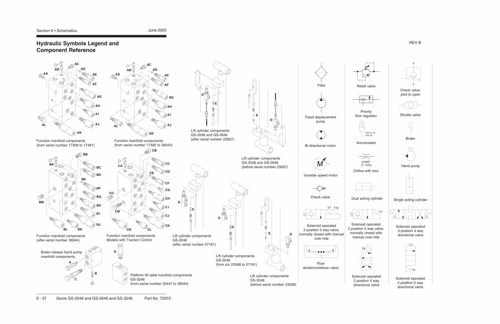
AC
ADAA
AB
AF
AE
AG
AH
AJ
AK
AL
AI
AC
ADAA
AB
AF
AE
AG
AH
AJ
AK
AL
AI
BA
BB
BC
BD
BF
BG
BH
BJ
BKBL
BM
B I
BE
CA
CB
CC
CD
CF
CG
CH
CJ
CKCLCN
CO
CMC I
CE
D
E
D
E
A
C
B
G
D
E
D
E
DE
Hydraulic Symbols Legend andComponent Reference
Section 6 • Schematics June 2003
Function manifold components(from serial number 17408 to 17481)
Function manifold components(after serial number 36044)
Function manifold componentsModels with Traction Control
Lift cylinder componentsGS-2046 and GS-2646(after serial number 23567)
6 - 37 Genie GS-2046 and GS-2646 and GS-3246 Part No. 72972
Function manifold components(from serial number 17482 to 36044)
Brake release hand pumpmanifold components
Platform lift relief manifold componentsGS-3246(from serial number 22447 to 36044)
Lift cylinder componentsGS-2046 and GS-2646(before serial number 23567)
Lift cylinder componentsGS-3246(after serial number 27181)
Lift cylinder componentsGS-3246(from s/n 23568 to 27181)
Lift cylinder componentsGS-3246(before serial number 23568)
Filter
Fixed displacementpump
Bi-directional motor
Variable speed motor
Check valve
Solenoid operated2 position 2 way valve,
normally closed with manualover-ride
Flowdivider/combiner valve
Relief valve
Priorityflow regulator
Accumulator
Orifice with size
Dual acting cylinder
Solenoid operated2 position 2 way valve,normally closed with
manual over-ride
Solenoid operated2 position 4 waydirectional valve
Check valve,pilot to open
Shuttle valve
Brake
Hand pump
Single acting cylinder
Solenoid operated3 position 4 waydirectional valve
Solenoid operated2 position 2 waydirectional valve
REV B
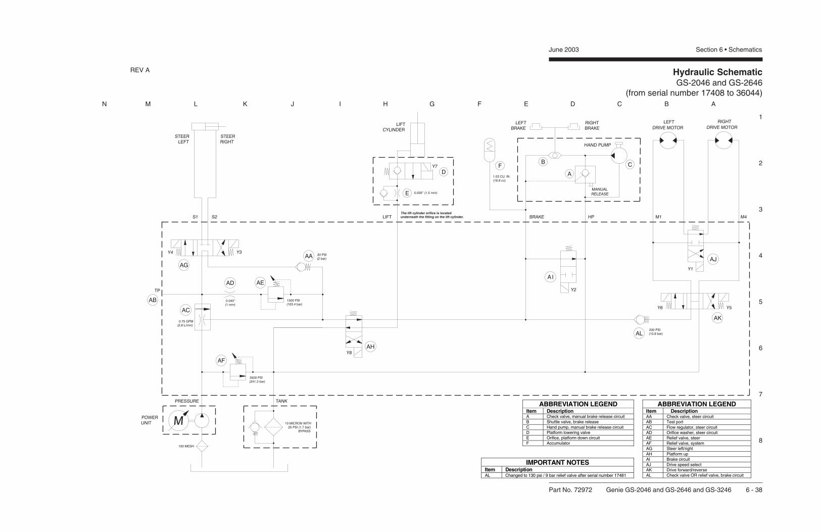
Hydraulic SchematicGS-2046 and GS-2646
(from serial number 17408 to 36044)
1
2
3
4
5
6
7
8
N M L K J I H G F E D C B A
Part No. 72972 Genie GS-2046 and GS-2646 and GS-3246 6 - 38
June 2003 Section 6 • Schematics
The lift cylinder orifice is locatedunderneath the fitting on the lift cylinder.
IMPORTANT NOTESItem DescriptionAL Changed to 130 psi / 9 bar relief valve after serial number 17481
ABBREVIATION LEGENDItem DescriptionA Check valve, manual brake release circuitB Shuttle valve, brake releaseC Hand pump, manual brake release circuitD Platform lowering valveE Orifice, platform down circuitF Accumulator
ABBREVIATION LEGENDItem DescriptionAA Check valve, steer circuitAB Test portAC Flow regulator, steer circuitAD Orifice washer, steer circuitAE Relief valve, steerAF Relief valve, systemAG Steer left/rightAH Platform upAI Brake circuitAJ Drive speed selectAK Drive forward/reverseAL Check valve OR relief valve, brake circuit
REV A

Hydraulic SchematicGS-2046 and GS-2646
(from serial number 17408 to 36044)
April 2003 Section 6 • Schematics
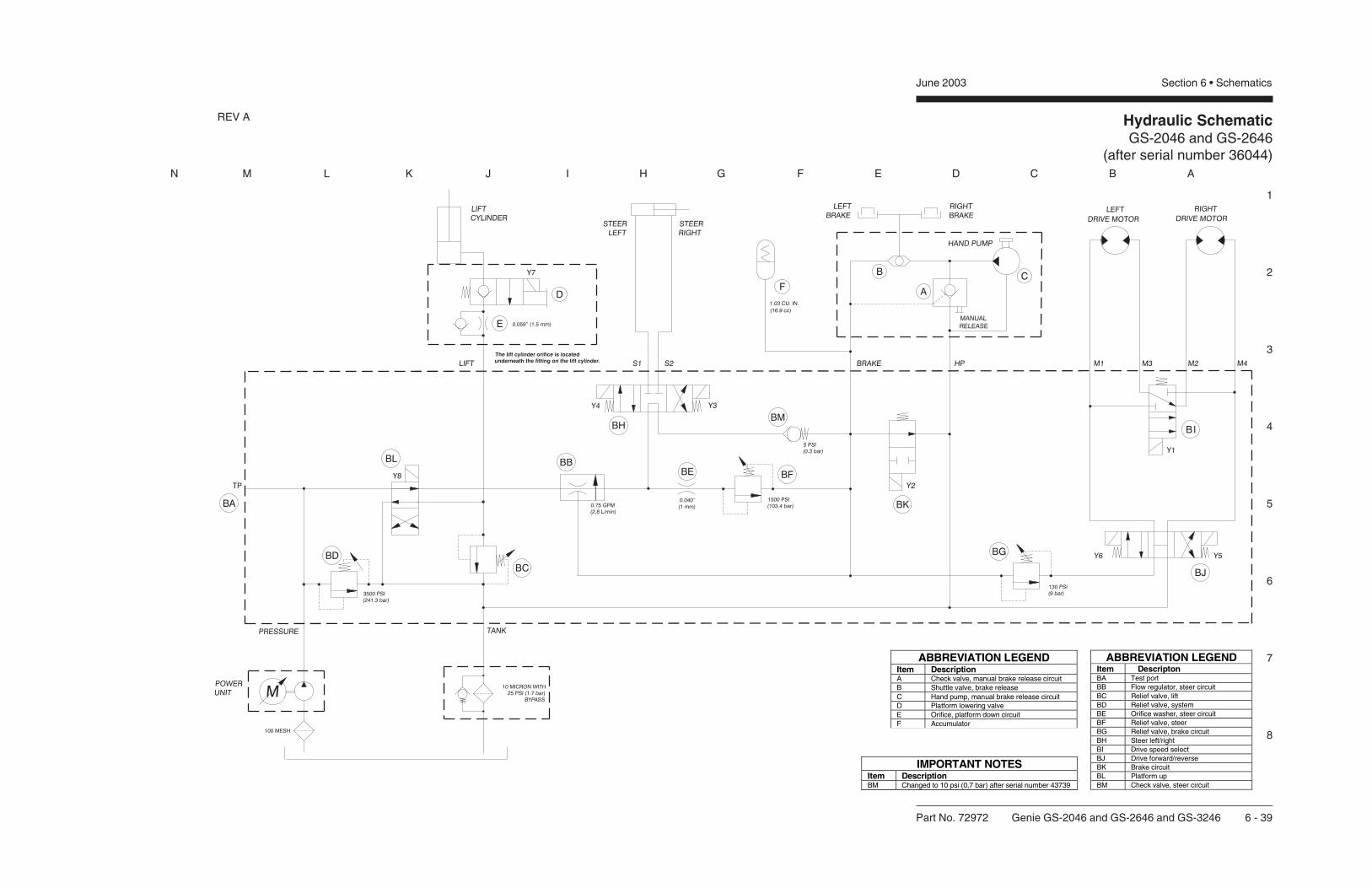
Hydraulic SchematicGS-2046 and GS-2646
(after serial number 36044)
1
2
3
4
5
6
7
8
N M L K J I H G F E D C B A
Part No. 72972 Genie GS-2046 and GS-2646 and GS-3246 6 - 39
June 2003 Section 6 • Schematics
The lift cylinder orifice is locatedunderneath the fitting on the lift cylinder.
ABBREVIATION LEGENDItem DescriptonBA Test portBB Flow regulator, steer circuitBC Relief valve, liftBD Relief valve, systemBE Orifice washer, steer circuitBF Relief valve, steerBG Relief valve, brake circuitBH Steer left/rightBI Drive speed selectBJ Drive forward/reverseBK Brake circuitBL Platform upBM Check valve, steer circuit
ABBREVIATION LEGENDItem DescriptionA Check valve, manual brake release circuitB Shuttle valve, brake releaseC Hand pump, manual brake release circuitD Platform lowering valveE Orifice, platform down circuitF Accumulator
IMPORTANT NOTESItem DescriptionBM Changed to 10 psi (0,7 bar) after serial number 43739
REV A

Hydraulic SchematicGS-2046 and GS-2646
(after serial number 36044)
June 2003 Section 6 • Schematics
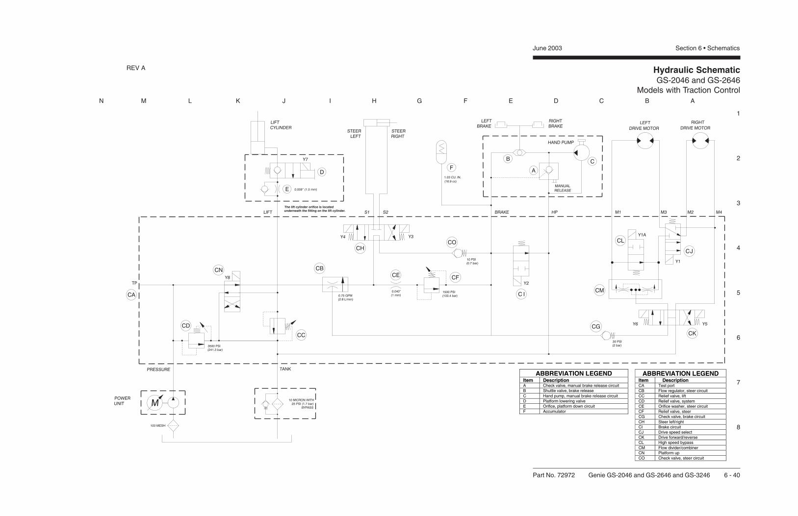
Hydraulic SchematicGS-2046 and GS-2646
Models with Traction Control
1
2
3
4
5
6
7
8
N M L K J I H G F E D C B A
Part No. 72972 Genie GS-2046 and GS-2646 and GS-3246 6 - 40
June 2003 Section 6 • Schematics
The lift cylinder orifice is locatedunderneath the fitting on the lift cylinder.
ABBREVIATION LEGENDItem DescriptionCA Test portCB Flow regulator, steer circuitCC Relief valve, liftCD Relief valve, systemCE Orifice washer, steer circuitCF Relief valve, steerCG Check valve, brake circuitCH Steer left/rightCI Brake circuitCJ Drive speed selectCK Drive forward/reverseCL High speed bypassCM Flow divider/combinerCN Platform upCO Check valve, steer circuit
ABBREVIATION LEGENDItem DescriptionA Check valve, manual brake release circuitB Shuttle valve, brake releaseC Hand pump, manual brake release circuitD Platform lowering valveE Orifice, platform down circuitF Accumulator
REV A

Hydraulic SchematicGS-2046 and GS-2646
Models with Traction Control
June 2003 Section 6 • Schematics
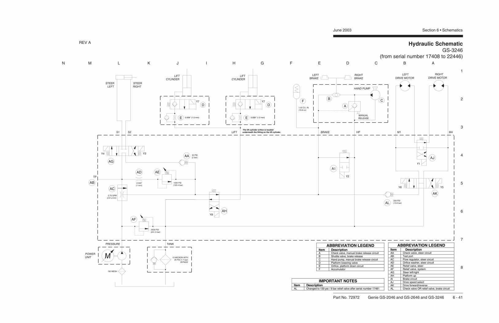
Hydraulic SchematicGS-3246
(from serial number 17408 to 22446)
1
2
3
4
5
6
7
8
N M L K J I H G F E D C B A
Part No. 72972 Genie GS-2046 and GS-2646 and GS-3246 6 - 41
June 2003 Section 6 • Schematics
The lift cylinder orifice is locatedunderneath the fitting on the lift cylinder.
IMPORTANT NOTESItem DescriptionAL Changed to 130 psi / 9 bar relief valve after serial number 17481
ABBREVIATION LEGENDItem DescriptionAA Check valve, steer circuitAB Test portAC Flow regulator, steer circuitAD Orifice washer, steer circuitAE Relief valve, steerAF Relief valve, systemAG Steer left/rightAH Platform upAI Brake circuitAJ Drive speed selectAK Drive forward/reverseAL Check valve OR relief valve, brake circuit
ABBREVIATION LEGENDItem DescriptionA Check valve, manual brake release circuitB Shuttle valve, brake releaseC Hand pump, manual brake release circuitD Platform lowering valveE Orifice, platform down circuitF Accumulator
REV A

Hydraulic SchematicGS-3246
(from serial number 17408 to 22446)
June 2003 Section 6 • Schematics
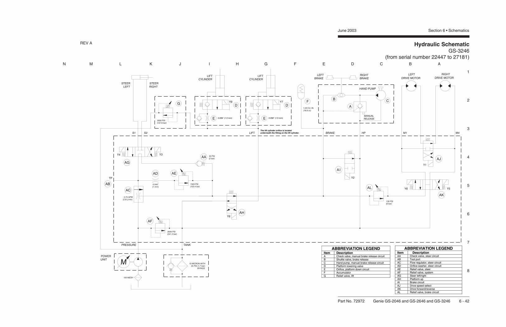
N M L K J I H G F E D C B A
The lift cylinder orifice is locatedunderneath the fitting on the lift cylinder.
REV A Hydraulic SchematicGS-3246
(from serial number 22447 to 27181)
1
2
3
4
5
6
7
8
Part No. 72972 Genie GS-2046 and GS-2646 and GS-3246 6 - 42
June 2003 Section 6 • Schematics
ABBREVIATION LEGENDItem DescriptionAA Check valve, steer circuitAB Test portAC Flow regulator, steer circuitAD Orifice washer, steer circuitAE Relief valve, steerAF Relief valve, systemAG Steer left/rightAH Platform upAI Brake circuitAJ Drive speed selectAK Drive forward/reverseAL Relief valve, brake circuit
ABBREVIATION LEGENDItem DescriptionA Check valve, manual brake release circuitB Shuttle valve, brake releaseC Hand pump, manual brake release circuitD Platform lowering valveE Orifice, platform down circuitF AccumulatorG Relief valve, lift

Hydraulic SchematicGS-3246
(from serial number 22447 to 27181)
June 2003 Section 6 • Schematics
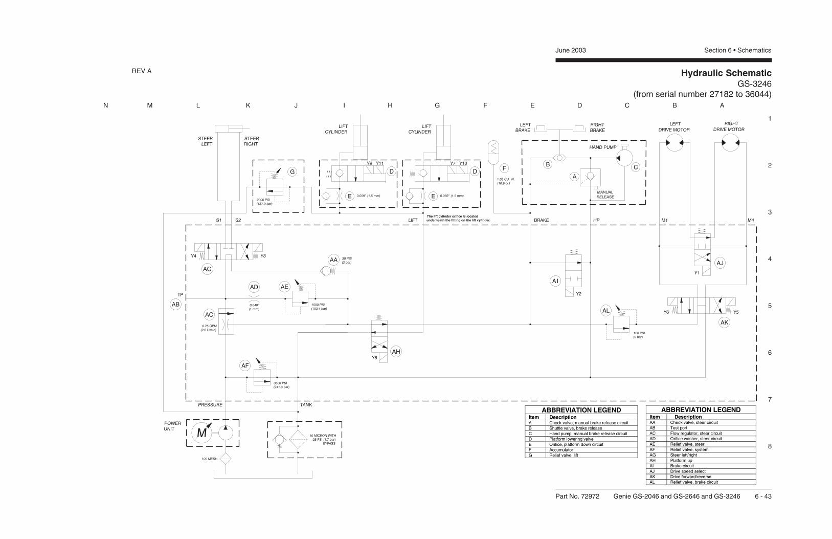
Hydraulic SchematicGS-3246
(from serial number 27182 to 36044)
1
2
3
4
5
6
7
8
N M L K J I H G F E D C B A
Part No. 72972 Genie GS-2046 and GS-2646 and GS-3246 6 - 43
June 2003 Section 6 • Schematics
The lift cylinder orifice is locatedunderneath the fitting on the lift cylinder.
ABBREVIATION LEGENDItem DescriptionAA Check valve, steer circuitAB Test portAC Flow regulator, steer circuitAD Orifice washer, steer circuitAE Relief valve, steerAF Relief valve, systemAG Steer left/rightAH Platform upAI Brake circuitAJ Drive speed selectAK Drive forward/reverseAL Relief valve, brake circuit
ABBREVIATION LEGENDItem DescriptionA Check valve, manual brake release circuitB Shuttle valve, brake releaseC Hand pump, manual brake release circuitD Platform lowering valveE Orifice, platform down circuitF AccumulatorG Relief valve, lift
REV A

Hydraulic SchematicGS-3246
(from serial number 27182 to 36044)
June 2003 Section 6 • Schematics

Hydraulic SchematicGS-3246
(after serial number 36044)
1
2
3
4
5
6
7
8
N M L K J I H G F E D C B A
Part No. 72972 Genie GS-2046 and GS-2646 and GS-3246 6 - 44
June 2003 Section 6 • Schematics
The lift cylinder orifice is locatedunderneath the fitting on the lift cylinder.
ABBREVIATION LEGENDItem DescriptonBA Test portBB Flow regulator, steer circuitBC Relief valve, liftBD Relief valve, systemBE Orifice washer, steer circuitBF Relief valve, steerBG Relief valve, brake circuitBH Steer left/rightBI Drive speed selectBJ Drive forward/reverseBK Brake circuitBL Platform upBM Check valve, steer circuit
ABBREVIATION LEGENDItem DescriptionA Check valve, manual brake release circuitB Shuttle valve, brake releaseC Hand pump, manual brake release circuitD Platform lowering valveE Orifice, platform down circuitF Accumulator
IMPORTANT NOTESItem DescriptionBM Changed to 10 psi / 0.7 bar after serial number 43739
REV A

Hydraulic SchematicGS-3246
(after serial number 36044)
June 2003 Section 6 • Schematics
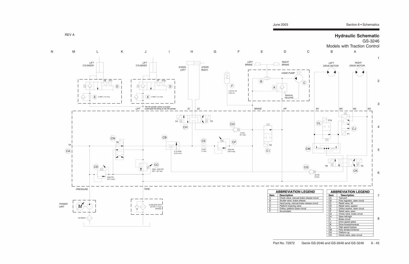
N M L K J I H G F E D C B A
The lift cylinder orifice is locatedunderneath the fitting on the lift cylinder.
REV A Hydraulic SchematicGS-3246
Models with Traction Control
1
2
3
4
5
6
7
8
Part No. 72972 Genie GS-2046 and GS-2646 and GS-3246 6 - 45
June 2003 Section 6 • Schematics
ABBREVIATION LEGENDItem DescriptionCA Test portCB Flow regulator, steer circuitCC Relief valve, liftCD Relief valve, systemCE Orifice washer, steer circuitCF Relief valve, steerCG Check valve, brake circuitCH Steer left/rightCI Brake circuitCJ Drive speed selectCK Drive forward/reverseCL High speed bypassCM Flow divider/combinerCN Platform upCO Check valve, steer circuit
ABBREVIATION LEGENDItem DescriptionA Check valve, manual brake release circuitB Shuttle valve, brake releaseC Hand pump, manual brake release circuitD Platform lowering valveE Orifice, platform down circuitF Accumulator
Hydraulic SchematicGS-3246
Models with Traction Control
June 2003 Section 6 • Schematics

Se
rv
ice
Ma
nu
al
GS
-20
46
&G
S-2
64
6&
GS
-32
46
Part No.
72972
Rev B2
Dis
trib
ute
d B
y:
Genie North America
Genie Australia Pty Ltd.
Genie China
Genie Malaysia
Genie Japan
Genie Korea
Genie Brasil
Genie Holland
Phone 425.881.1800
Toll Free USA and Canada
800.536.1800
Fax 425.883.3475
Phone +61 7 3375 1660
Fax +61 7 3375 1002
Phone +86 21 53852570
Fax +86 21 53852569
Phone +65 98 480 775
Fax +65 67 533 544
Phone +81 3 3453 6082
Fax +81 3 3453 6083
Phone +82 25 587 267
Fax +82 25 583 910
Phone +55 11 41 665 755
Fax +55 11 41 665 754
Phone +31 183 581 102
Fax +31 183 581 566
Genie Scandinavia
Genie France
Genie Iberica
Genie Germany
Genie U.K.
Genie Mexico City
Phone +46 31 575100
Fax +
Phone +33 (0)2 37 26 09 99
Fax +33 (0)2 37 26 09 98
Phone +34 93 579 5042
Fax +34 93 579 5059
Phone 0800 180 9017
Fax +49 422 149 1820
Phone +44 (0)1476 584333
Fax +44 (0)1476 584334
Phone +52 55 5666 5242
Fax +52 55 5666 3241
46 31 579020
Phone +49 422 149 1818