Generator protection REG650 ANSI Product Guide
96
Relion ® 650 series Generator protection REG650 ANSI Product Guide
Transcript of Generator protection REG650 ANSI Product Guide
Relion® 650 series
Generator protection REG650 ANSIProduct Guide
Contents
1. 650 series overview...........................................................3
2. Application.........................................................................3
3. Available functions.............................................................6
4. Differential protection.......................................................14
5. Impedance protection......................................................15
6. Current protection............................................................16
7. Voltage protection............................................................19
8. Frequency protection.......................................................21
9. Secondary system supervision.........................................21
10. Control...........................................................................22
11. Logic..............................................................................23
12. Monitoring......................................................................24
13. Metering.........................................................................26
14. Human Machine interface...............................................27
15. Basic IED functions.........................................................27
16. Station communication...................................................28
17. Hardware description......................................................29
18. Connection diagrams Customized..................................31
19. Connection diagrams Configured....................................36
20. Technical data................................................................49
21. Ordering for Customized IED..........................................84
22. Ordering for Configured IED............................................89
23. Ordering for Accessories................................................92
Disclaimer
The information in this document is subject to change without notice and should not be construed as a commitment by ABB. ABB assumes no responsibility for any errors
that may appear in this document.
© Copyright 2012 ABB.
All rights reserved.
Trademarks
ABB and Relion are registered trademarks of the ABB Group. All other brand or product names mentioned in this document may be trademarks or registered trademarks
of their respective holders.
Generator protection REG650 ANSI 1MRK 502 045-BUS B
Product version: 1.2
2 ABB

1. 650 series overviewThe 650 series IEDs provide both customized andconfigured solutions. With the customized IEDs youhave the freedom to completely adapt thefunctionality according to your needs.
The 650 series IEDs provide optimum 'off-the-shelf', ready-to-use solutions. It is configured withcomplete protection functionality and defaultparameters to meet the needs of a wide range ofapplications for generation, transmission and sub-transmission grids.
The 650 series IEDs include:• Customized versions providing the possibility to
adapt the functionality to the application needs.• Configured solutions are completely ready to use
solutions optimized for a wide range ofapplications for generation, transmission and sub-transmission grids.
• Support for user-defined names in the locallanguage for signal and function engineering.
• Minimized parameter settings based on defaultvalues and ABB's new global base value concept.You only need to set those parameters specific toyour own application, such as the line data.
• GOOSE messaging for horizontal communication.• Extended HMI functionality with 15 dynamic three-
color-indication LEDs per page, on up to threepages, and configurable push-button shortcutsfor different actions.
• Programmable LED text-based labels.• Settable 1A/5A -rated current inputs.
2. ApplicationREG650 is used for the protection and monitoringof generating plants. The IED is especially suitablefor applications in distributed control systems withhigh demands on reliability. It is intended mainly forsmall and medium size generation stations.
REG670 may be used when more extensiveprotection systems are required or in combinationwith REG650 to provide redundant schemes.
A wide range of protection functions is available toachieve full and reliable protection for different typesof generating plants, for example hydro powerplants and thermal power plants. This enablesadaptation to the protection requirements of mostgenerating plants.
Protection functions are available for detecting andclearing internal faults, such as generator statorshort circuits and ground faults, generator rotorground faults, unit transformer short circuits andground faults and faults in the external powersystem, fed from the generating plant.
Two packages have been defined for the followingapplications:
• Generator protection IED including generatordifferential protection (B01A)
• Generator-transformer unit protection IEDincluding transformer differential protection(B05A)
In many generating plants, the protection systemcan be designed with a combination of the twopackages, that is, two IEDs of either same type ordifferent types, will give redundant protection for agenerating unit (generator and unit transformer)depending on the requirements for the plant design.
The packages are configured and ready for use.Analogue inputs and binary input/output circuits arepre-defined.
The pre-configured IED can be changed andadapted with the graphical configuration tool.
Generator protection REG650 ANSI 1MRK 502 045-BUS B
Product version: 1.2 Issued: June 2012Revision: B
ABB 3

A, B, C or D
~
59N UN>
STEF PHIZ
59THD U3d/N
REG650-B01
TR PTTR
49 Ith
LEX PDIS
40
OEX PVPH
24 U/f>
UV2 PTUV
27 3U<
OV2 PTOV
59 3U>
OC4 PTOC
51 3I>
GEN PDIF
87G 3Id/I
SA PTUF
81U f<
110kV HV Substation
VR2 PVOC
51V I>/U<21 Z<
AEG GAPC
50AE U</I>
SA PTOF
81O f>
SDD RFUF
60FL
Note:
1) Input for independent non-directional OC and overload functions. It can be used for different purposes (e.g. OC protection for either Auxiliary trafo or Excitation trafo or Step-up transformer HV side)
I
V
NS2 PTOC
46 I2>
OC4 PTOC
51 3I>
CC RPLD
52PD PD
CC RBRF
50BF 3I> BF
Generator CB
AuxiliaryTransformer
UnitTransformer
29MVA121/11kV
YNd5
ExcitationTransformer
HV CB
ROV2 PTOV
59N 3Uo>
TR PTTR
49 Ith
OOS PPAM
78 Ucos
SES RSYN
25 SC
1)
2)
3)
3) Input for independent directional (sensitive) EF function. It can be used for different purposes (e.g. as rotor EF with RXTTE4 or stator EF for generators operating in parallel)
Fiel
d C
B
HZ PDIF
87N IdN
2) Input for independent non-directional EF function. It can be used for different purposes (e.g. as stator EF protection or turn-to-turn protection for generators with split winding or even HV side EF protection). Alternatively it can be used for High-Impedance REF protection.
ROV2 PTOV
59N 3Uo>
CV MMXN
Meter.
GOP PDOP
32
GOP PDUP
37 P<
TRM module with 4I+1I*+5U AIM module with 6I+4U
¤)
¤) Requires dedicated CT cores, external resistor and metrosil for correct operation
V MSQI
47 U2>
EF4 PTOC
67N
SDE PSDE
67N
Rotor EF protection 64R
GOP PDOP
32Q
SA PFRC
81R df/dt
390kVA11/0.37kV
Dyn11
50/5
1600/5
1600/5
10/1
1.6MVA11/0.4kV
EF4 PTOC
51N IN>
110.110.11//
333kV
110.110.11//
333kV
11/0.11
3kV
200/1
100/52500/5
1000
29MVA11kV
150rpm
RX
TTE
4
D
C B
A
H J, G or H
200/5
G
Y200/1
J
C MSQI
Meter.
ANSI11000140-2-en.vsd
Q
P
IN> IN> <
ZGC PDIS
Y
Y
Y
Y
4) An example to indicate the functions, marked in black are enabled in settings.
ANSI11000140 V2 EN
Figure 1. Generator protection IED including generator differential protection (B01A)
Generator protection REG650 ANSI 1MRK 502 045-BUS B
Product version: 1.2
4 ABB
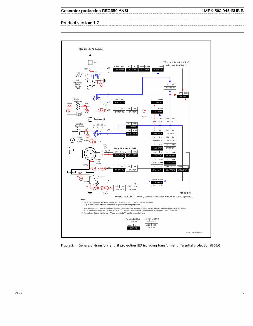
~
STEF PHIZ
59THD U3d/N
REG650-B05
LEX PDIS
40
GOP PDOP
32
OEX PVPH
24 U/f>
UV2 PTUV
27 3U<
OV2 PTOV
59 3U>
T3D PDIF
87T 3Id/I
SA PTUF
81U f<
110 kV HV Substation
VR2 PVOC
51V I>/U<
ZGC PDIS
21 Z<
AEG GAPC
50AE U</I>
SA PTOF
81O f>
I
U
NS2 PTOC
46 I2>
OC4 PTOC
51 3I>
CC RPLD
52PD PD
CC RBRF
50BF 3I > BF
Generator CB
HV CB
ROV2 PTOV
59N 3Uo>
TR PTTR
49 Ith
OOS PPAM
78 Ucos
SES RSYN
25 SC
Note:
2)
1)
Inputs for independent directional (sensitive) EF function. It can be used for different purposes. (e.g. as rotor EF with RXTTE4 or stator EF for generators running in parallel)
1)
2)
Fiel
d C
B
TR PTTR
49 Ith
OC4 PTOC
51 3I>
HZ PDIF
87N IdN
EF4 PTOC
51N IN>
GT01
ROV2 PTOV
59N 3Uo>
59N UN>
CV MMXN
Meter.
GUP PDUP
37 P<
TRM module with 4I+1I*+5 U AIM module with 6I+4U
¤)
¤) Requires dedicated CT cores , external resistor and metrosil for correct operation
V MSQI
47 U2>
EF4 PTOC
67N
SDE PSDE
67N
Rotor EF protection 64R
CV MMXN
Meter.
GOP PDOP
32Q
SA PFRC
81R df/dt
3)
3)
Alternatively step up transformer HV side open delta VT can be connected here
Generator CB
AuxiliaryTransformer
ExcitationTransformer
50/5
1600/5
29MVA11kV
150rpm
200/1
100/5
11/
333kV
1100.110.11//
333kV
11/0.11
3kV
2500/5
1000
RX
TTE
4
C
B
E
A
D
A or B
D or E
200/5
G
1600/5
10/1H J , G or H
Y 200/1
J
SDD RFUF
60FL
C MSQI
Meter.
.
IN> IN>
Q
P
<
ANSI11000141-2-en.vsd
YY
390kVA11/0.37kV
Dyn11
1.6MVA11/0.4kV
UnitTransformer
29MVA121/11kV
YNd5
YY
Y
Y
/0.11 0.11
3
Input for independent non-directional EF function. It can be used for different purposes (e.g. as stator EF protection or turn-to-turn protection for generators with split winding or even HV side EF protection). Alternatively it can be used for High-Impedance REF protection.
Function Disabled in Settings
IEC61850 IEC61850IEC IECANSI
Function Enabled in Settings
ANSI
ANSI11000141 V2 EN
Figure 2. Generator-transformer unit protection IED including transformer differential protection (B05A)
Generator protection REG650 ANSI 1MRK 502 045-BUS B
Product version: 1.2
ABB 5
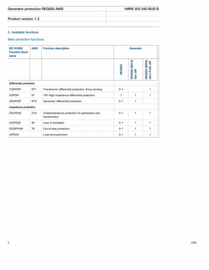
3. Available functions
Main protection functions
IEC 61850/Function blockname
ANSI Function description Generator
RE
G65
0
RE
G65
0 (B
01A
)G
en d
iff
RE
G65
0 (B
05A
)G
en+
Tra
fo d
iff
Differential protection
T3WPDIF 87T Transformer differential protection, three winding 0–1 1
HZPDIF 87 1Ph High impedance differential protection 1 1 1
GENPDIF 87G Generator differential protection 0–1 1
Impedance protection
ZGCPDIS 21G Underimpedance protection for generators andtransformers
0–1 1 1
LEXPDIS 40 Loss of excitation 0–1 1 1
OOSPPAM 78 Out-of-step protection 0–1 1 1
LEPDIS Load encroachment 0–1 1 1
Generator protection REG650 ANSI 1MRK 502 045-BUS B
Product version: 1.2
6 ABB

Back-up protection functions
IEC 61850/Functionblock name
ANSI Function description Generator
RE
G65
0
RE
G65
0 (B
01A
)G
en d
iff
RE
G65
0 (B
05A
)G
en+
Tra
fo d
iff
Current protection
OC4PTOC 51 Four step phase overcurrent protection, 3–phase output 0–2 2 2
EF4PTOC 51N/67N Four step residual overcurrent protection, zero/negativesequence direction
0–2 2 2
SDEPSDE 67N Sensitive directional residual overcurrent and powerprotection
0–1 1 1
TRPTTR 49 Thermal overload protection, two time constants 0–2 2 2
CCRBRF 50BF Breaker failure protection, 3–phase activation and output 0–1 1 1
CCRPLD 52PD Pole discordance protection 0–1 1 1
GUPPDUP 37 Directional underpower protection 0–1 1 1
GOPPDOP 32 Directional overpower protection 0–2 2 2
AEGGAPC 50AE Accidental energizing protection for synchronousgenerator
0–1 1 1
NS2PTOC 46I2 Negative-sequence time overcurrent protection formachines
0–1 1 1
VR2PVOC 51V Voltage-restrained time overcurrent protection 0–1 1 1
Voltage protection
UV2PTUV 27 Two step undervoltage protection 0–1 1 1
OV2PTOV 59 Two step overvoltage protection 0–1 1 1
ROV2PTOV 59N Two step residual overvoltage protection 0–2 2 2
OEXPVPH 24 Overexcitation protection 0–1 1 1
STEFPHIZ 59THD 100% Stator earth fault protection, 3rd harmonic based 0–1 1 1
- 64R Rotor ground protection with RXTTE4 injection unit 0–1 0–1 0–1
Frequency protection
SAPTUF 81 Underfrequency function 0–4 4 4
SAPTOF 81 Overfrequency function 0–4 4 4
SAPFRC 81 Rate-of-change frequency protection 0–2 2 2
Generator protection REG650 ANSI 1MRK 502 045-BUS B
Product version: 1.2
ABB 7

Control and monitoring functions
IEC 61850/Functionblock name
ANSI Function description Generator
RE
G65
0
RE
G65
0 (B
01A
)G
en d
iff
RE
G65
0 (B
05A
)G
en+
Tra
fo d
iff
Control
SESRSYN 25 Synchrocheck, energizing check, and synchronizing 0–1 1 1
QCBAY Bay control 1 1 1
LOCREM Handling of LR-switch positions 1 1 1
LOCREMCTRL LHMI control of Permitted Source To Operate(PSTO)
1 1 1
CBC1 Circuit breaker for 1CB 0–1 1
CBC2 Circuit breaker for 2CB 0–1 1
SLGGIO Logic Rotating Switch for function selection andLHMI presentation
15 15 15
VSGGIO Selector mini switch extension 20 20 20
DPGGIO IEC 61850 generic communication I/O functionsdouble point
16 16 16
SPC8GGIO Single point generic control 8 signals 5 5 5
AUTOBITS AutomationBits, command function for DNP3.0 3 3 3
I103CMD Function commands for IEC60870-5-103 1 1 1
I103IEDCMD IED commands for IEC60870-5-103 1 1 1
I103USRCMD Function commands user defined forIEC60870-5-103
4 4 4
I103GENCMD Function commands generic for IEC60870-5-103 50 50 50
I103POSCMD IED commands with position and select forIEC60870-5-103
50 50 50
Secondary system supervision
SDDRFUF Fuse failure supervision 0–1 1 1
TCSSCBR Breaker close/trip circuit monitoring 3 3 3
Logic
SMPPTRC 94 Tripping logic, common 3–phase output 1–6 6 6
TMAGGIO Trip matrix logic 12 12 12
OR Configurable logic blocks, OR gate 283 283 283
Generator protection REG650 ANSI 1MRK 502 045-BUS B
Product version: 1.2
8 ABB
IEC 61850/Functionblock name
ANSI Function description Generator
RE
G65
0
RE
G65
0 (B
01A
)G
en d
iff
RE
G65
0 (B
05A
)G
en+
Tra
fo d
iff
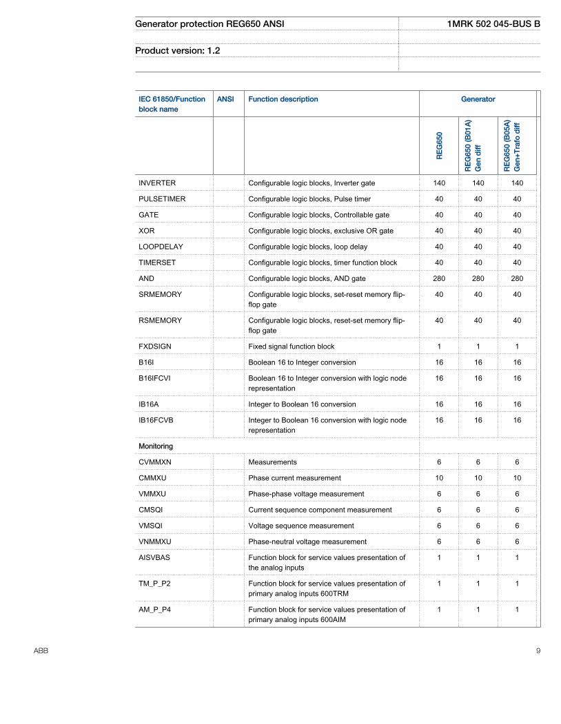
INVERTER Configurable logic blocks, Inverter gate 140 140 140
PULSETIMER Configurable logic blocks, Pulse timer 40 40 40
GATE Configurable logic blocks, Controllable gate 40 40 40
XOR Configurable logic blocks, exclusive OR gate 40 40 40
LOOPDELAY Configurable logic blocks, loop delay 40 40 40
TIMERSET Configurable logic blocks, timer function block 40 40 40
AND Configurable logic blocks, AND gate 280 280 280
SRMEMORY Configurable logic blocks, set-reset memory flip-flop gate
40 40 40
RSMEMORY Configurable logic blocks, reset-set memory flip-flop gate
40 40 40
FXDSIGN Fixed signal function block 1 1 1
B16I Boolean 16 to Integer conversion 16 16 16
B16IFCVI Boolean 16 to Integer conversion with logic noderepresentation
16 16 16
IB16A Integer to Boolean 16 conversion 16 16 16
IB16FCVB Integer to Boolean 16 conversion with logic noderepresentation
16 16 16
Monitoring
CVMMXN Measurements 6 6 6
CMMXU Phase current measurement 10 10 10
VMMXU Phase-phase voltage measurement 6 6 6
CMSQI Current sequence component measurement 6 6 6
VMSQI Voltage sequence measurement 6 6 6
VNMMXU Phase-neutral voltage measurement 6 6 6
AISVBAS Function block for service values presentation ofthe analog inputs
1 1 1
TM_P_P2 Function block for service values presentation ofprimary analog inputs 600TRM
1 1 1
AM_P_P4 Function block for service values presentation ofprimary analog inputs 600AIM
1 1 1
Generator protection REG650 ANSI 1MRK 502 045-BUS B
Product version: 1.2
ABB 9

IEC 61850/Functionblock name
ANSI Function description Generator
RE
G65
0
RE
G65
0 (B
01A
)G
en d
iff
RE
G65
0 (B
05A
)G
en+
Tra
fo d
iff
TM_S_P2 Function block for service values presentation ofsecondary analog inputs 600TRM
1 1 1
AM_S_P4 Function block for service values presentation ofsecondary analog inputs 600AIM
1 1 1
CNTGGIO Event counter 5 5 5
DRPRDRE Disturbance report 1 1 1
AxRADR Analog input signals 4 4 4
BxRBDR Binary input signals 6 6 6
SPGGIO IEC 61850 generic communication I/O functions 64 64 64
SP16GGIO IEC 61850 generic communication I/O functions 16inputs
16 16 16
MVGGIO IEC 61850 generic communication I/O functions 16 16 16
MVEXP Measured value expander block 66 66 66
SPVNZBAT Station battery supervision 0–1 1 1
SSIMG 63 Insulation gas monitoring function 0–2 2 2
SSIML 71 Insulation liquid monitoring function 0–2 2 2
SSCBR Circuit breaker condition monitoring 0–1 1 1
I103MEAS Measurands for IEC60870-5-103 1 1 1
I103MEASUSR Measurands user defined signals forIEC60870-5-103
3 3 3
I103AR Function status auto-recloser for IEC60870-5-103 1 1 1
I103EF Function status ground-fault for IEC60870-5-103 1 1 1
I103FLTPROT Function status fault protection for IEC60870-5-103 1 1 1
I103IED IED status for IEC60870-5-103 1 1 1
I103SUPERV Supervison status for IEC60870-5-103 1 1 1
I103USRDEF Status for user defined signals for IEC60870-5-103 20 20 20
Metering
PCGGIO Pulse counter logic 16 16 16
ETPMMTR Function for energy calculation and demandhandling
3 3 3
Generator protection REG650 ANSI 1MRK 502 045-BUS B
Product version: 1.2
10 ABB
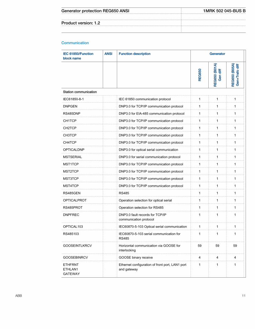
Communication
IEC 61850/Functionblock name
ANSI Function description Generator
RE
G65
0
RE
G65
0 (B
01A
)G
en d
iff
RE
G65
0 (B
05A
)G
en+
Tra
fo d
iff
Station communication
IEC61850-8-1 IEC 61850 communication protocol 1 1 1
DNPGEN DNP3.0 for TCP/IP communication protocol 1 1 1
RS485DNP DNP3.0 for EIA-485 communication protocol 1 1 1
CH1TCP DNP3.0 for TCP/IP communication protocol 1 1 1
CH2TCP DNP3.0 for TCP/IP communication protocol 1 1 1
CH3TCP DNP3.0 for TCP/IP communication protocol 1 1 1
CH4TCP DNP3.0 for TCP/IP communication protocol 1 1 1
OPTICALDNP DNP3.0 for optical serial communication 1 1 1
MSTSERIAL DNP3.0 for serial communication protocol 1 1 1
MST1TCP DNP3.0 for TCP/IP communication protocol 1 1 1
MST2TCP DNP3.0 for TCP/IP communication protocol 1 1 1
MST3TCP DNP3.0 for TCP/IP communication protocol 1 1 1
MST4TCP DNP3.0 for TCP/IP communication protocol 1 1 1
RS485GEN RS485 1 1 1
OPTICALPROT Operation selection for optical serial 1 1 1
RS485PROT Operation selection for RS485 1 1 1
DNPFREC DNP3.0 fault records for TCP/IPcommunication protocol
1 1 1
OPTICAL103 IEC60870-5-103 Optical serial communication 1 1 1
RS485103 IEC60870-5-103 serial communication forRS485
1 1 1
GOOSEINTLKRCV Horizontal communication via GOOSE forinterlocking
59 59 59
GOOSEBINRCV GOOSE binary receive 4 4 4
ETHFRNTETHLAN1GATEWAY
Ethernet configuration of front port, LAN1 portand gateway
1 1 1
Generator protection REG650 ANSI 1MRK 502 045-BUS B
Product version: 1.2
ABB 11

IEC 61850/Functionblock name
ANSI Function description Generator
RE
G65
0
RE
G65
0 (B
01A
)G
en d
iff
RE
G65
0 (B
05A
)G
en+
Tra
fo d
iff
GOOSEDPRCV GOOSE function block to receive a doublepoint value
32 32 32
GOOSEINTRCV GOOSE function block to receive an integervalue
32 32 32
GOOSEMVRCV GOOSE function block to receive a measurandvalue
16 16 16
GOOSESPRCV GOOSE function block to receive a single pointvalue
64 64 64
Generator protection REG650 ANSI 1MRK 502 045-BUS B
Product version: 1.2
12 ABB
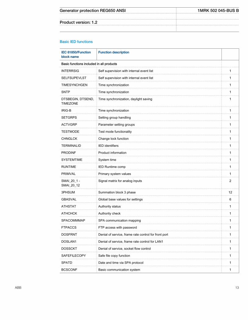
Basic IED functions
IEC 61850/Functionblock name
Function description
Basic functions included in all products
INTERRSIG Self supervision with internal event list 1
SELFSUPEVLST Self supervision with internal event list 1
TIMESYNCHGEN Time synchronization 1
SNTP Time synchronization 1
DTSBEGIN, DTSEND,TIMEZONE
Time synchronization, daylight saving 1
IRIG-B Time synchronization 1
SETGRPS Setting group handling 1
ACTVGRP Parameter setting groups 1
TESTMODE Test mode functionality 1
CHNGLCK Change lock function 1
TERMINALID IED identifiers 1
PRODINF Product information 1
SYSTEMTIME System time 1
RUNTIME IED Runtime comp 1
PRIMVAL Primary system values 1
SMAI_20_1 -SMAI_20_12
Signal matrix for analog inputs 2
3PHSUM Summation block 3 phase 12
GBASVAL Global base values for settings 6
ATHSTAT Authority status 1
ATHCHCK Authority check 1
SPACOMMMAP SPA communication mapping 1
FTPACCS FTP access with password 1
DOSFRNT Denial of service, frame rate control for front port 1
DOSLAN1 Denial of service, frame rate control for LAN1 1
DOSSCKT Denial of service, socket flow control 1
SAFEFILECOPY Safe file copy function 1
SPATD Date and time via SPA protocol 1
BCSCONF Basic communication system 1
Generator protection REG650 ANSI 1MRK 502 045-BUS B
Product version: 1.2
ABB 13
4. Differential protection
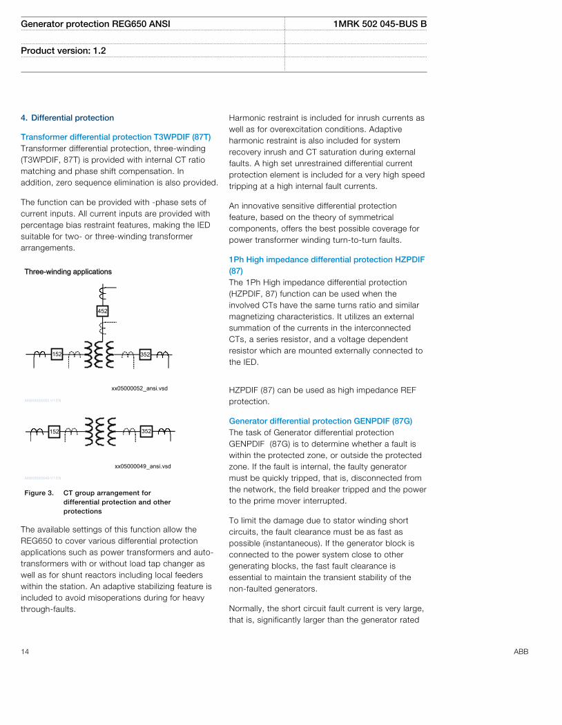
Transformer differential protection T3WPDIF (87T)Transformer differential protection, three-winding(T3WPDIF, 87T) is provided with internal CT ratiomatching and phase shift compensation. Inaddition, zero sequence elimination is also provided.
The function can be provided with -phase sets ofcurrent inputs. All current inputs are provided withpercentage bias restraint features, making the IEDsuitable for two- or three-winding transformerarrangements.
Three-winding applications
xx05000052_ansi.vsd
352152
452
ANSI05000052 V1 EN
xx05000049_ansi.vsd
152 352
ANSI05000049 V1 EN
Figure 3. CT group arrangement fordifferential protection and otherprotections
The available settings of this function allow theREG650 to cover various differential protectionapplications such as power transformers and auto-transformers with or without load tap changer aswell as for shunt reactors including local feederswithin the station. An adaptive stabilizing feature isincluded to avoid misoperations during for heavythrough-faults.
Harmonic restraint is included for inrush currents aswell as for overexcitation conditions. Adaptiveharmonic restraint is also included for systemrecovery inrush and CT saturation during externalfaults. A high set unrestrained differential currentprotection element is included for a very high speedtripping at a high internal fault currents.
An innovative sensitive differential protectionfeature, based on the theory of symmetricalcomponents, offers the best possible coverage forpower transformer winding turn-to-turn faults.
1Ph High impedance differential protection HZPDIF(87)The 1Ph High impedance differential protection(HZPDIF, 87) function can be used when theinvolved CTs have the same turns ratio and similarmagnetizing characteristics. It utilizes an externalsummation of the currents in the interconnectedCTs, a series resistor, and a voltage dependentresistor which are mounted externally connected tothe IED.
HZPDIF (87) can be used as high impedance REFprotection.
Generator differential protection GENPDIF (87G)The task of Generator differential protectionGENPDIF (87G) is to determine whether a fault iswithin the protected zone, or outside the protectedzone. If the fault is internal, the faulty generatormust be quickly tripped, that is, disconnected fromthe network, the field breaker tripped and the powerto the prime mover interrupted.
To limit the damage due to stator winding shortcircuits, the fault clearance must be as fast aspossible (instantaneous). If the generator block isconnected to the power system close to othergenerating blocks, the fast fault clearance isessential to maintain the transient stability of thenon-faulted generators.
Normally, the short circuit fault current is very large,that is, significantly larger than the generator rated
Generator protection REG650 ANSI 1MRK 502 045-BUS B
Product version: 1.2
14 ABB

current. There is a risk that a short circuit can occurbetween phases close to the neutral point of thegenerator, thus causing a relatively small faultcurrent. The fault current can also be limited due tolow excitation of the generator. Therefore, it isdesired that the detection of generator phase-to-phase short circuits shall be relatively sensitive,detecting small fault currents.
It is also of great importance that the generatordifferential protection does not trip for externalfaults, with large fault currents flowing from thegenerator. To combine fast fault clearance, as wellas sensitivity and selectivity, the generatordifferential protection is normally the best choice forphase-to-phase generator short circuits. A negative-sequence-current-based internal-external faultdiscriminator can also be used to determinewhether a fault is internal or external. The internal-external fault discriminator not only positivelydiscriminates between internal and external faults,but can independently detect minor faults whichmay not be felt (until they develop into more seriousfaults) by the "usual" differential protection based onoperate-restrain characteristic.
An open CT circuit condition creates unexpectedoperations for Generator differential protectionunder the normal load conditions. It is also possibleto damage secondary equipment due to highvoltage produced from open CT circuit outputs.Therefore, it may be a requirement from securityand reliability points of view to have open CTdetection function to block Generator differentialprotection function in case of open CT conditionsand at the same time produce the alarm signal tothe operational personal to make quick remedyactions to correct the open CT condition.
Generator differential protection GENPDIF (87G) isalso well suited to generate fast, sensitive andselective fault clearance, if used to protect shuntreactors or small busduct.
5. Impedance protection
Underimpedance protection for generators andtransformers ZGCPDIS (21)The underimpedance protection for generators andtransformers ZGCPDIS(21G), has the offset mhocharacteristic as a three zone back-up protectionfor detection of phase-to-phase short circuits intransformers and generators. The three zones haveindependent measuring and settings that gives highflexibility for all types of applications.
A load encroachment characteristic is available forthe third zone as shown in figure 4.
en07000117.vsd
jX
Operation area Operation area
R
Operation area
No operation area No operation area
IEC07000117 V1 EN
Figure 4. Load encroachment influence on the offsetmho Z3 characteristic
Loss of excitation LEXPDIS (40)There are limits for the low excitation of asynchronous machine. A reduction of the excitationcurrent weakens the coupling between the rotorand the stator. The machine may lose thesynchronism and start to operate like an inductionmachine. Then, the reactive power consumption willincrease. Even if the machine does not loosesynchronism it may not be acceptable to operate inthis state for a long time. Reduction of excitationincreases the generation of heat in the end region ofthe synchronous machine. The local heating may
Generator protection REG650 ANSI 1MRK 502 045-BUS B
Product version: 1.2
ABB 15

damage the insulation of the stator winding and theiron core.
To prevent damages to the generator it should betripped when excitation becomes too low.
The impedance measurement is used for LEXPDISfunction. Its operating characteristic is designed astwo zone, offset mho circles and a directionalelement restrain line.
Out-of-step protection OOSPPAM (78)Out-of-step protection (OOSPPAM, 78) function inthe IED can be used both for generator protectionapplication as well as, line protection applications.
The main purpose of the OOSPPAM, 78 function isto detect, evaluate, and take the required actionduring pole slipping occurrences in the powersystem.
The OOSPPAM, 78 function detects pole slipconditions and trips the generator as fast aspossible, after the first pole-slip if the center ofoscillation is found to be in zone 1, which normallyincludes the generator and its step-up powertransformer. If the center of oscillation is found tobe further out in the power system, in zone 2, morethan one pole-slip is usually allowed before thegenerator-transformer unit is disconnected. If thereare several out-of-step relays in the power system,then the one which finds the center of oscillation inits zone 1 should operate first.
Load encroachment LEPDISHeavy load transfer is common in many powernetworks and may make fault resistance coveragedifficult to achieve. In such a case, Loadencroachment (LEPDIS) function can be used toprevent operation of the of the underimpedancemeasuring zones during heavy loads.
6. Current protection
Four step phase overcurrent protection, 3-phaseoutput OC4PTOC (51/67)The four step phase overcurrent protection functionOC4PTOC (51/67) has independent inverse time
delay settings for step 1 and 4. Step 2 and 3 arealways definite time delayed.
All IEC and ANSI inverse time characteristics areavailable.
The directional function is voltage polarized withmemory. The function can be set to be directionalor non-directional independently for each of thesteps.
A 2nd harmonic blocking can be set individually foreach step.
Four step residual overcurrent protection, zerosequence and negative sequence directionEF4PTOC (51N_67N)The four step residual overcurrent protection, zeroor negative sequence direction (EF4PTOC, 51N/67N) has independent inverse time delay settingsfor step 1 and 4. Step 2 and 3 are always definitetime delayed.
All IEC and ANSI inverse time characteristics areavailable.
EF4PTOC (51N/67N) can be set directional or non-directional independently for each of the steps.
The directional part of the function can be set tooperate on following combinations:• Directional current (I3PDir) versus Polarizing
voltage (V3PPol)• Directional current (I3PDir) versus Polarizing
current (I3PPol)• Directional current (I3PDir) versus Dual polarizing
(VPol+ZPol x IPol) where ZPol = RPol + jXPol
IDir, VPol and IPol can be independently selected tobe either zero sequence or negative sequence.
Second harmonic blocking restraint level can be setfor the function and can be used to block each stepindividually.
Sensitive directional residual overcurrent andpower protection SDEPSDE (67N)In isolated networks or in networks with highimpedance grounding, the ground fault current issignificantly smaller than the short circuit currents.
Generator protection REG650 ANSI 1MRK 502 045-BUS B
Product version: 1.2
16 ABB

In addition to this, the magnitude of the fault currentis almost independent on the fault location in thenetwork. The protection can be selected to useeither the residual current or residual powercomponent 3V0·3I0·cos j, for operating quantity.
There is also available one non-directional 3I0 step
and one non-directional 3V0 overvoltage tripping
step.
Thermal overload protection, two time constantTRPTTR (49)If a power transformer or generator reaches veryhigh temperatures the equipment might bedamaged. The insulation within the transformer/generator will have forced ageing. As aconsequence of this the risk of internal phase-to-phase or phase-to-ground faults will increase. Hightemperature will degrade the quality of thetransformer/generator insulation.
The thermal overload protection estimates theinternal heat content of the transformer/generator(temperature) continuously. This estimation is madeby using a thermal model of the transformer/generator with two time constants, which is basedon current measurement.
Two warning pickup levels are available. Thisenables actions in the power system to be donebefore dangerous temperatures are reached. If thetemperature continues to increase to the trip value,the protection initiates a trip of the protectedtransformer/generator.
Breaker failure protection, 3-phase activation andoutput (50BF)CCRBRF (50BF) can be current based, contactbased, or an adaptive combination of these twoconditions.
Breaker failure protection (CCRBRF, 50BF) ensuresfast back-up tripping of surrounding breakers incase the protected breaker fails to open. CCRBRF(50BF) can be current based, contact based, or anadaptive combination of these two conditions.
Current check with extremely short reset time isused as check criterion to achieve high securityagainst unnecessary operation.
Contact check criteria can be used where the faultcurrent through the breaker is small.
Breaker failure protection, 3-phase activation andoutput (CCRBRF, 50BF) current criteria can befulfilled by one or two phase currents the residualcurrent, or one phase current plus residual current.When those currents exceed the user definedsettings, the function is triggered. These conditionsincrease the security of the back-up trip command.
CCRBRF (50BF) function can be programmed togive a three-phase re-trip of the protected breakerto avoid unnecessary tripping of surroundingbreakers.
Pole discordance protection CCRPLD (52PD)Circuit breakers and disconnectors can end up withtheir phases in different positions (close-open), dueto electrical or mechanical failures. An open phasecan cause negative and zero sequence currentswhich cause thermal stress on rotating machinesand can cause unwanted operation of zerosequence or negative sequence current functions.
Normally the affected breaker is tripped to correctsuch a situation. If the situation warrants thesurrounding breakers should be tripped to clear theunsymmetrical load situation.
The pole discrepancy function operates based oninformation from the circuit breaker logic withadditional criteria from unsymmetrical phasecurrents when required.
Directional over/underpower protection GOPPDOP/GUPPDUP (32/37)The directional over-/under-power protectionGOPPDOP (32)/GUPPDUP (37) can be usedwherever a high/low active, reactive or apparentpower protection or alarming is required. Thefunctions can alternatively be used to check thedirection of active or reactive power flow in thepower system. There are a number of applicationswhere such functionality is needed. Some of themare:
• detection of reversed active power flow• detection of high reactive power flow
Generator protection REG650 ANSI 1MRK 502 045-BUS B
Product version: 1.2
ABB 17
Each function has two steps with definite timedelay. Reset times for both steps can be set as well.
Accidental energizing protection for synchronousgenerator AEGGAPC (50AE)Inadvertent or accidental energizing of off-linegenerators has occurred often enough due tooperating errors, breaker head flashovers, controlcircuit malfunctions, or a combination of thesecauses. Inadvertently energized generator operatesas induction motor drawing a large current from thesystem. The voltage supervised overcurrentprotection is used to protect the inadvertentlyenergized generator.
Accidental energizing protection for synchronousgenerator (AEGGAPC, 50AE) takes the maximumphase current input from the generator terminal sideor from generator neutral side and maximum phaseto phase voltage inputs from the terminal side.AEGGAPC (50AE) is enabled when the terminalvoltage drops below the specified voltage level forthe preset time.
Negative sequence time overcurrent protection formachines NS2PTOC (46I2)Negative-sequence time overcurrent protection formachines NS2PTOC (46I2) is intended primarily forthe protection of generators against possibleoverheating of the rotor caused by negativesequence current in the stator current.
The negative sequence currents in a generator may,among others, be caused by:
• Unbalanced loads• Line to line faults• Line to ground faults• Broken conductors• Malfunction of one or more poles of a circuit
breaker or a disconnector
NS2PTOC (46I2) can also be used as a backupprotection, that is, to protect the generator in caseline protections or circuit breakers fail to clearunbalanced system faults.
To provide an effective protection for the generatorfor external unbalanced conditions, NS2PTOC(46I2) is able to directly measure the negative
sequence current. NS2PTOC (46I2) also has a timedelay characteristic which matches the heating
characteristic of the generator 2
2I t K= as defined
in standard IEEE C50.13.
where:
I2 is negative sequence currentexpressed in per unit of the ratedgenerator current
t is operating time in seconds
K is a constant which depends of thegenerators size and design
NS2PTOC (46I2) has a wide range of K settings andthe sensitivity and capability of detecting andtripping for negative sequence currents down to thecontinuous capability of a generator.
A separate output is available as an alarm feature towarn the operator of a potentially dangeroussituation.
Voltage-restrained time overcurrent protectionVR2PVOC (51V)Voltage-restrained time overcurrent protection(VR2PVOC, 51V) function is recommended as abackup protection for generators.
The overcurrent protection feature has a settablecurrent level that can be used either with definitetime or inverse time characteristic. Additionally, itcan be voltage controlled/restrained.
One undervoltage step with definite timecharacteristic is also available with the function inorder to provide funcionality for overcurrentprotection with undervoltage seal-in.
Rotor ground fault protection (64R)Generator rotor winding and its associated dcsupply electric circuit is typically fully insulated fromthe ground. Therefore single connection of thiscircuit to ground will not cause flow of anysubstantial current. However, if second ground-faultappears in this circuit circumstances can be quitserious. Depending on the location of these twofaults such operating condition may cause:
Generator protection REG650 ANSI 1MRK 502 045-BUS B
Product version: 1.2
18 ABB
• Partial or total generator loss of field• Large dc current flow through rotor magnetic
circuit• Rotor vibration• Rotor displacement sufficient to cause stator
mechanical damage
Therefore practically all bigger generators havesome dedicated protection which is capable todetect the first ground-fault in the rotor circuit andthen, depending on the fault resistance, either justto give an alarm to the operating personnel oractually to give stop command to the machine. Aninjection unit is required for rotor ground faultprotection (RXTTE4) and a protective resistor onplate for correct operation. Either SDEPSDE orEF4PTOC function can be used in conjunction withRXTTE4 as rotor earth-fault protection.
7. Voltage protection
Two step undervoltage protection UV2PTUV (27)Undervoltages can occur in the power systemduring faults or abnormal conditions. Two stepundervoltage protection (UV2PTUV, 27) functioncan be used to open circuit breakers to prepare forsystem restoration at power outages or as long-time delayed back-up to primary protection.
UV2PTUV (27) has two voltage steps, where step 1is settable as inverse or definite time delayed. Step2 is always definite time delayed.
Two step overvoltage protection OV2PTOV (59)Overvoltages may occur in the power system duringabnormal conditions such as sudden power loss,tap changer regulating failures, open line ends onlong lines etc.
OV2PTOV (59) has two voltage steps, where step 1can be set as inverse or definite time delayed. Step2 is always definite time delayed.
OV2PTOV (59) has an extremely high reset ratio toallow settings close to system service voltage.
Two step residual overvoltage protectionROV2PTOV (59N)Residual voltages may occur in the power systemduring ground faults.
Two step residual overvoltage protectionROV2PTOV (59N) function calculates the residualvoltage from the three-phase voltage inputtransformers or measures it from a single voltageinput transformer fed from a broken delta or neutralpoint voltage transformer.
ROV2PTOV (59N) has two voltage steps, wherestep 1 can be set as inverse or definite timedelayed. Step 2 is always definite time delayed.
Overexcitation protection OEXPVPH (24)When the laminated core of a power transformer orgenerator is subjected to a magnetic flux densitybeyond its design limits, stray flux will flow into non-laminated components not designed to carry fluxand cause eddy currents to flow. The eddy currentscan cause excessive heating and severe damage toinsulation and adjacent parts in a relatively shorttime. The function has settable inverse operatingcurves and independent alarm stages.
95% and 100% Stator earth fault protection basedon 3rd harmonic STEFPHIZ (59TD)Stator ground fault is a fault type having relativelyhigh fault rate. The generator systems normallyhave high impedance grounding, that is, groundingvia a neutral point resistor. This resistor is normallydimensioned to give an ground fault current in therange 3 – 15 A at a solid ground-fault directly at thegenerator high voltage terminal. The relatively smallground fault currents give much less thermal andmechanical stress on the generator, compared tothe short circuit case, which is between conductorsof two phases. Anyhow, the ground faults in thegenerator have to be detected and the generatorhas to be tripped, even if longer fault timecompared to internal short circuits, can be allowed.
In normal non-faulted operation of the generatingunit the neutral point voltage is close to zero, andthere is no zero sequence current flow in thegenerator. When a phase-to-ground fault occurs
Generator protection REG650 ANSI 1MRK 502 045-BUS B
Product version: 1.2
ABB 19

the neutral point voltage will increase and there willbe a current flow through the neutral point resistor.
To detect a ground fault on the windings of agenerating unit one may use a neutral pointovervoltage protection, a neutral point overcurrentprotection, a zero sequence overvoltage protectionor a residual differential protection. Theseprotections are simple and have served well duringmany years. However, at best these simpleschemes protect only 95% of the stator winding.They leave 5% close to the neutral endunprotected. Under unfavorable conditions the blindzone may extend up to 20% from the neutral.
The 95% stator ground fault protection measuresthe fundamental frequency voltage component in
the generator star point and it operates when itexceeds the preset value. By applying this principleapproximately 95% of the stator winding can beprotected. In order to protect the last 5% of thestator winding close to the neutral end the 3rdharmonic voltage measurement can be performed.In 100% Stator E/F 3rd harmonic protection eitherthe 3rd harmonic voltage differential principle, theneutral point 3rd harmonic undervoltage principle orthe terminal side 3rd harmonic overvoltage principlecan be applied. However, differential principle isstrongly recommended. Combination of these twomeasuring principles provides coverage for entirestator winding against ground faults.
x E3
Rf
TCB 2(1-x) E3
over- voltage protection 10% – 100%
Differential0% – 30%
CB 1 may not exist
RN
NCB 1
stator winding
uTuN
x E3
Rf Transformer
TCB 2(1-x) E3
x
Neutral point fundamental frequency over-voltage protection 5% - 100%
3rd harmonic differential0% - 30%
CB 1 may not exist
1 or 100 %
RN
NNCB 1
stator winding
uTuN 1 - x1 - xSamples of the neutral voltage from which the
fundamental and 3rd harmonic voltages are filtered out
Samples of the terminal voltage from which the 3rd harmonic
voltage is filtered out
ANSI10000202-1-en.vsd
ANSI10000202 V1 EN
Figure 5. Protection principles for STEFPHIZ (59TD) function
Generator protection REG650 ANSI 1MRK 502 045-BUS B
Product version: 1.2
20 ABB
8. Frequency protection
Underfrequency protection SAPTUF (81)Underfrequency occurs as a result of a lack ofsufficient generation in the network.
Underfrequency protection SAPTUF (81) is used forload shedding systems, remedial action schemes,gas turbine startup and so on.
SAPTUF (81) is also provided with undervoltageblocking.
Overfrequency protection SAPTOF (81)Overfrequency protection function SAPTOF (81) isapplicable in all situations, where reliable detectionof high fundamental power system frequency isneeded.
Overfrequency occurs because of sudden loaddrops or shunt faults in the power network. Close tothe generating plant, generator governor problemscan also cause over frequency.
SAPTOF (81) is used mainly for generation sheddingand remedial action schemes. It is also used as afrequency stage initiating load restoring.
SAPTOF (81) is provided with an undervoltageblocking.
Rate-of-change frequency protection SAPFRC (81)Rate-of-change frequency protection function(SAPFRC,81) gives an early indication of a maindisturbance in the system. SAPFRC (81) can beused for generation shedding, load shedding andremedial action schemes. SAPFRC (81) candiscriminate between positive or negative change offrequency.
SAPFRC (81) is provided with an undervoltageblocking.
9. Secondary system supervision
Fuse failure supervision SDDRFUFThe aim of the fuse failure supervision function(SDDRFUF) is to block voltage measuring functionsat failures in the secondary circuits between the
voltage transformer and the IED in order to avoidunwanted operations that otherwise might occur.
The fuse failure supervision function basically hasthree different algorithms, negative sequence andzero sequence based algorithms and an additionaldelta voltage and delta current algorithm.
The negative sequence detection algorithm isrecommended for IEDs used in isolated or high-impedance grounded networks. It is based on thenegative-sequence measuring quantities, a highvalue of negative sequence voltage 3V2 without the
presence of the negative-sequence current 3I2.
The zero sequence detection algorithm isrecommended for IEDs used in directly or lowimpedance grounded networks. It is based on thezero sequence measuring quantities, a high value ofzero sequence voltage 3V0 without the presence of
the zero sequence current 3I0.
For better adaptation to system requirements, anoperation mode setting has been introduced whichmakes it possible to select the operating conditionsfor negative sequence and zero sequence basedfunction. The selection of different operation modesmakes it possible to choose different interactionpossibilities between the negative sequence andzero sequence based algorithm.
A criterion based on delta current and delta voltagemeasurements can be added to the fuse failuresupervision function in order to detect a threephase fuse failure, which in practice is moreassociated with voltage transformer switchingduring station operations.
Breaker close/trip circuit monitoring TCSSCBRThe trip circuit monitoring function TCSSCBR isdesigned for supervision of control circuits. A faultin a control circuit is detected by using a dedicatedoutput contact that contains the monitoringfunctionality.
The function picks up and trips when TCSSCBRdetects a trip circuit failure. The trip timecharacteristic for the function is of definite time (DT)
Generator protection REG650 ANSI 1MRK 502 045-BUS B
Product version: 1.2
ABB 21
type. The function trips after a predefined operatingtime and resets when the fault disappears.
10. Control
Synchrocheck, energizing check, andsynchronizing SESRSYN (25)The Synchronizing function allows closing ofasynchronous networks at the correct momentincluding the breaker closing time, which improvesthe network stability.
Synchrocheck, energizing check, and synchronizing(SESRSYN, 25) function checks that the voltages onboth sides of the circuit breaker are in synchronism,or with at least one side dead to ensure that closingcan be done safely.
SESRSYN (25) function includes a built-in voltageselection scheme for double bus and breaker-and-a-half or ring busbar arrangements.
Manual closing as well as automatic reclosing canbe checked by the function and can have differentsettings.
For systems which are running asynchronous asynchronizing function is provided. The mainpurpose of the synchronizing function is to providecontrolled closing of circuit breakers when twoasynchronous systems are going to be connected.It is used for slip frequencies that are larger thanthose for synchronism check and lower than a setmaximum level for the synchronizing function.
However this function can not be used toautomatically synchronize the generator to thenetwork.
Bay control QCBAYThe Bay control QCBAY function is used togetherwith Local remote and local remote controlfunctions to handle the selection of the operatorplace per bay. QCBAY also provides blockingfunctions that can be distributed to differentapparatuses within the bay.
Local remote LOCREM /Local remote controlLOCREMCTRLThe signals from the local HMI or from an externallocal/remote switch are applied via the functionblocks LOCREM and LOCREMCTRL to the Baycontrol (QCBAY) function block. A parameter infunction block LOCREM is set to choose if theswitch signals are coming from the local HMI orfrom an external hardware switch connected viabinary inputs.
Circuit breaker control for circuit breakers, CBC1and CBC2The CBC1 and CBC2 consists of 3 functions each:
• SCILO - The Logical node for interlocking.SCILO function is used to enable a switchingoperation if the interlocking conditions permit.SCILO function itself does not provide anyinterlocking functionality. The interlockingconditions are generated in separate functionblocks containing the interlocking logic.
• SCSWI - The Switch controller initializes andsupervises all functions to properly select andoperate switching primary apparatuses. TheSwitch controller may handle and operate onone three-phase device.
• SXCBR - The purpose of SXCBR is to providethe actual status of positions and to performthe control operations, that is, pass all thecommands to primary apparatuses in the formof circuit breakers via output boards and tosupervise the switching operation and position.
Logic rotating switch for function selection andLHMI presentation SLGGIOThe logic rotating switch for function selection andLHMI presentation (SLGGIO) (or the selector switchfunction block) is used to get a selector switchfunctionality similar to the one provided by ahardware selector switch. Hardware selectorswitches are used extensively by utilities, in order tohave different functions operating on pre-set values.Hardware switches are however sources formaintenance issues, lower system reliability and anextended purchase portfolio. The logic selectorswitches eliminate all these problems.
Generator protection REG650 ANSI 1MRK 502 045-BUS B
Product version: 1.2
22 ABB

Selector mini switch VSGGIOThe Selector mini switch VSGGIO function block isa multipurpose function used for a variety ofapplications, as a general purpose switch.
VSGGIO can be controlled from the menu or from asymbol on the single line diagram (SLD) on the localHMI.
IEC 61850 generic communication I/O functionsDPGGIOThe IEC 61850 generic communication I/Ofunctions (DPGGIO) function block is used to senddouble indications to other systems or equipment inthe substation. It is especially used in theinterlocking and reservation station-wide logics.
Single point generic control 8 signals SPC8GGIOThe Single point generic control 8 signals(SPC8GGIO) function block is a collection of 8single point commands, designed to bring incommands from REMOTE (SCADA) to those partsof the logic configuration that do not need extensivecommand receiving functionality (for example,SCSWI). In this way, simple commands can be sentdirectly to the IED outputs, without confirmation.Confirmation (status) of the result of the commandsis supposed to be achieved by other means, suchas binary inputs and SPGGIO function blocks. Thecommands can be pulsed or steady.
AutomationBits AUTOBITSThe Automation bits function (AUTOBITS) is used toconfigure the DNP3 protocol command handling.
11. Logic
Tripping logic common 3-phase output SMPPTRC(94)A function block for protection tripping is providedfor each circuit breaker involved in the tripping ofthe fault. It provides pulse prolongation to ensure athree-phase trip pulse of sufficient length, as well asall functionality necessary for correct co-operationwith autoreclosing functions.
The trip function block also includes functionality forbreaker lock-out.
Trip matrix logic TMAGGIOThe Trip matrix logic TMAGGIO function is used toroute trip signals and other logical output signals tothe tripping logics SMPPTRC and SPTPTRC or todifferent output contacts on the IED.
TMAGGIO output signals and the physical outputsallows the user to adapt the signals to the physicaltripping outputs according to the specificapplication needs.
Configurable logic blocksA number of logic blocks and timers are availablefor the user to adapt the configuration to thespecific application needs.
• OR function block.
• INVERTER function blocks that inverts the inputsignal.
• PULSETIMER function block can be used, forexample, for pulse extensions or limiting ofoperation of outputs, settable pulse time.
• GATE function block is used for whether or not asignal should be able to pass from the input tothe output.
• XOR function block.
• LOOPDELAY function block used to delay theoutput signal one execution cycle.
• TIMERSET function has pick-up and drop-outdelayed outputs related to the input signal. Thetimer has a settable time delay and must beEnabled for the input signal to activate the outputwith the appropriate time delay.
• AND function block.
• SRMEMORY function block is a flip-flop that canset or reset an output from two inputsrespectively. Each block has two outputs whereone is inverted. The memory setting controls if theblock's output should reset or return to the stateit was, after a power interruption. The SET inputhas priority if both SET and RESET inputs areoperated simultaneously.
Generator protection REG650 ANSI 1MRK 502 045-BUS B
Product version: 1.2
ABB 23
• RSMEMORY function block is a flip-flop that canreset or set an output from two inputsrespectively. Each block has two outputs whereone is inverted. The memory setting controls if theblock's output should reset or return to the stateit was, after a power interruption. The RESETinput has priority if both SET and RESET areoperated simultaneously.
Boolean 16 to Integer conversion B16IBoolean 16 to integer conversion function (B16I) isused to transform a set of 16 binary (logical) signalsinto an integer.
Boolean 16 to Integer conversion with logic noderepresentation B16IFCVIBoolean 16 to integer conversion with logic noderepresentation function (B16IFCVI) is used totransform a set of 16 binary (logical) signals into aninteger.
Integer to Boolean 16 conversion IB16AInteger to boolean 16 conversion function (IB16A) isused to transform an integer into a set of 16 binary(logical) signals.
Integer to Boolean 16 conversion with logic noderepresentation IB16FCVBInteger to boolean conversion with logic noderepresentation function (IB16FCVB) is used totransform an integer to 16 binary (logic) signals.
IB16FCVB function can receive remote values overIEC61850 depending on the operator position input(PSTO).
12. Monitoring
IEC61850 generic communication I/O functionSPGGIOIEC61850 generic communication I/O functions(SPGGIO) is used to send one single logical signalto other systems or equipment in the substation.
IEC61850 generic communication 1/O function 16inputsIEC 61850 generic communication I/O functions 16inputs (SP16GGIO) function is used to send up to
16 logical signals to other systems or equipment inthe substation.
Measurements CVMMXN, CMMXU, VNMMXU,VMMXU, CMSQI, VMSQIThe measurement functions are used to get on-lineinformation from the IED. These service valuesmake it possible to display on-line information onthe local HMI and on the Substation automationsystem about:
• measured voltages, currents, frequency,active, reactive and apparent power and powerfactor
• primary and secondary phasors• current sequence components• voltage sequence components
Event counter CNTGGIOEvent counter (CNTGGIO) has six counters whichare used for storing the number of times eachcounter input has been activated.
Disturbance report DRPRDREComplete and reliable information aboutdisturbances in the primary and/or in the secondarysystem together with continuous event-logging isaccomplished by the disturbance reportfunctionality.
Disturbance report DRPRDRE, always included inthe IED, acquires sampled data of all selectedanalog input and binary signals connected to thefunction block with a, maximum of 40 analog and96 binary signals.
The Disturbance report functionality is a commonname for several functions:
• Sequential of events• Indications• Event recorder• Trip value recorder• Disturbance recorder
The Disturbance report function is characterized bygreat flexibility regarding configuration, initiatingconditions, recording times, and large storagecapacity.
Generator protection REG650 ANSI 1MRK 502 045-BUS B
Product version: 1.2
24 ABB
A disturbance is defined as an activation of an inputto the AxRADR or BxRBDR function blocks, whichare set to trigger the disturbance recorder. Allsignals from start of pre-fault time to the end ofpost-fault time will be included in the recording.
Every disturbance report recording is saved in theIED in the standard Comtrade format. The sameapplies to all events, which are continuously savedin a FIFO-buffer. The local HMI is used to getinformation about the recordings. The disturbancereport files may be uploaded to PCM600 for furtheranalysis using the disturbance handling tool.
Sequential of events DRPRDREContinuous event-logging is useful for monitoringthe system from an overview perspective and is acomplement to specific disturbance recorderfunctions.
The sequential of events logs all binary input signalsconnected to the Disturbance report function. Thelist may contain up to 1000 time-tagged eventsstored in a FIFO-buffer.
Indications DRPRDRETo get fast, condensed and reliable informationabout disturbances in the primary and/or in thesecondary system it is important to know, forexample binary signals that have changed statusduring a disturbance. This information is used in theshort perspective to get information via the localHMI in a straightforward way.
There are three LEDs on the local HMI (green,yellow and red), which will display status informationabout the IED and the Disturbance report function(triggered).
The Indication list function shows all selected binaryinput signals connected to the Disturbance reportfunction that have changed status during adisturbance.
Event recorder DRPRDREQuick, complete and reliable information aboutdisturbances in the primary and/or in the secondarysystem is vital, for example, time-tagged eventslogged during disturbances. This information isused for different purposes in the short term (for
example corrective actions) and in the long term (forexample functional analysis).
The event recorder logs all selected binary inputsignals connected to the Disturbance reportfunction. Each recording can contain up to 150 time-tagged events.
The event recorder information is available for thedisturbances locally in the IED.
The event recording information is an integratedpart of the disturbance record (Comtrade file).
Trip value recorder DRPRDREInformation about the pre-fault and fault values forcurrents and voltages are vital for the disturbanceevaluation.
The Trip value recorder calculates the values of allselected analog input signals connected to theDisturbance report function. The result is magnitudeand phase angle before and during the fault foreach analog input signal.
The trip value recorder information is available forthe disturbances locally in the IED.
The trip value recorder information is an integratedpart of the disturbance record (Comtrade file).
Disturbance recorder DRPRDREThe Disturbance recorder function supplies fast,complete and reliable information aboutdisturbances in the power system. It facilitatesunderstanding system behavior and related primaryand secondary equipment during and after adisturbance. Recorded information is used fordifferent purposes in the short perspective (forexample corrective actions) and long perspective(for example functional analysis).
The Disturbance recorder acquires sampled datafrom selected analog- and binary signals connectedto the Disturbance report function (maximum 40analog and 96 binary signals). The binary signalsavailable are the same as for the event recorderfunction.
The function is characterized by great flexibility andis not dependent on the operation of protection
Generator protection REG650 ANSI 1MRK 502 045-BUS B
Product version: 1.2
ABB 25

functions. It can record disturbances not detectedby protection functions. Up to three seconds ofdata before the trigger instant can be saved in thedisturbance file.
The disturbance recorder information for up to 100disturbances are saved in the IED and the local HMIis used to view the list of recordings.
Measured value expander block MVEXPThe current and voltage measurements functions(CVMMXN, CMMXU, VMMXU and VNMMXU),current and voltage sequence measurementfunctions (CMSQI and VMSQI) and IEC 61850generic communication I/O functions (MVGGIO) areprovided with measurement supervisionfunctionality. All measured values can be supervisedwith four settable limits: low-low limit, low limit, highlimit and high-high limit. The measure valueexpander block has been introduced to enabletranslating the integer output signal from themeasuring functions to 5 binary signals: below low-low limit, below low limit, normal, above high-highlimit or above high limit. The output signals can beused as conditions in the configurable logic or foralarming purpose.
Station battery supervision SPVNZBATThe station battery supervision function SPVNZBATis used for monitoring battery terminal voltage.
SPVNZBAT activates the start and alarm outputswhen the battery terminal voltage exceeds the setupper limit or drops below the set lower limit. A timedelay for the overvoltage and undervoltage alarmscan be set according to definite time characteristics.
In the definite time (DT) mode, SPVNZBAT operatesafter a predefined operate time and resets when thebattery undervoltage or overvoltage conditiondisappears after reset time.
Insulation gas monitoring function SSIMGInsulation gas monitoring function SSIMG (63) isused for monitoring the circuit breaker condition.Binary information based on the gas pressure in thecircuit breaker is used as input signals to thefunction. In addition, the function generates alarmsbased on received information.
Insulation liquid monitoring function SSIMLInsulation liquid monitoring function SSIML (71) isused for monitoring the circuit breaker condition.Binary information based on the oil level in thecircuit breaker is used as input signals to thefunction. In addition, the function generates alarmsbased on received information.
Circuit breaker monitoring SSCBRThe circuit breaker condition monitoring functionSSCBR is used to monitor different parameters ofthe circuit breaker. The breaker requiresmaintenance when the number of operations hasreached a predefined value. For proper functioningof the circuit breaker, it is essential to monitor thecircuit breaker operation, spring charge indication,breaker wear, travel time, number of operationcycles and accumulated energy. The energy iscalculated from the measured input currents as a
sum of I^2 t values. Alarms are generated when thecalculated values exceed the threshold settings.
The function contains a blocking functionality. It ispossible to block the function outputs, if desired.
13. Metering
Pulse counter logic PCGGIOPulse counter (PCGGIO) function counts externallygenerated binary pulses, for instance pulses comingfrom an external energy meter, for calculation ofenergy consumption values. The pulses arecaptured by the BIO (binary input/output) moduleand then read by the PCGGIO function. A scaledservice value is available over the station bus.
Function for energy calculation and demandhandling ETPMMTROutputs from the Measurements (CVMMXN)function can be used to calculate energyconsumption. Active as well as reactive values arecalculated in import and export direction. Valuescan be read or generated as pulses. Maximumdemand power values are also calculated by thefunction.
Generator protection REG650 ANSI 1MRK 502 045-BUS B
Product version: 1.2
26 ABB

14. Human Machine interface
Local HMI
ANSI12000175 V1 EN
Figure 6. Local human-machine interface
The LHMI of the IED contains the following elements:• Display (LCD)• Buttons• LED indicators• Communication port
The LHMI is used for setting, monitoring andcontrolling.
The Local human machine interface, LHMI includesa graphical monochrome LCD with a resolution of320x240 pixels. The character size may varydepending on selected language. The amount ofcharacters and rows fitting the view depends on thecharacter size and the view that is shown.
The LHMI is simple and easy to understand. Thewhole front plate is divided into zones, each with awell-defined functionality:
• Status indication LEDs• Alarm indication LEDs which can indicate three
states with the colors green, yellow and red,with user printable label. All LEDs areconfigurable from the PCM600 tool
• Liquid crystal display (LCD)• Keypad with push buttons for control and
navigation purposes, switch for selectionbetween local and remote control and reset
• Five user programmable function buttons• An isolated RJ45 communication port for
PCM600
15. Basic IED functions
Self supervision with internal event listThe Self supervision with internal event list(INTERRSIG and SELFSUPEVLST) function reactsto internal system events generated by the differentbuilt-in self-supervision elements. The internalevents are saved in an internal event list.
Time synchronizationUse a common global source for example GPS timesynchronization inside each substation as well asinside the area of the utility responsibility to achievea common time base for the IEDs in a protectionand control system. This makes comparison andanalysis of events and disturbance data between allIEDs in the power system possible.
Time-tagging of internal events and disturbancesare an excellent help when evaluating faults.Without time synchronization, only the events withinthe IED can be compared to one another. With timesynchronization, events and disturbances within theentire station, and even between line ends, can becompared during evaluation.
In the IED, the internal time can be synchronizedfrom a number of sources:
• SNTP• IRIG-B• DNP• IEC60870-5-103
Parameter setting groups ACTVGRPUse the four different groups of settings to optimizethe IED operation for different power systemconditions. Creating and switching between fine-tuned setting sets, either from the local HMI orconfigurable binary inputs, results in a highlyadaptable IED that can cope with a variety of powersystem scenarios.
Test mode functionality TESTMODEThe protection and control IEDs may have manyincluded functions. To make the testing procedureeasier, the IEDs include the feature that allowsindividual blocking of all functions except thefunction(s) the shall be tested.
Generator protection REG650 ANSI 1MRK 502 045-BUS B
Product version: 1.2
ABB 27

There are two ways of entering the test mode:
• By configuration, activating an input signal ofthe function block TESTMODE
• By setting the IED in test mode in the local HMI
While the IED is in test mode, all protectionfunctions are blocked.
Any function can be unblocked individuallyregarding functionality and event signaling. Thisenables the user to follow the operation of one orseveral related functions to check functionality andto check parts of the configuration, and so on.
Change lock function CHNGLCKChange lock function (CHNGLCK) is used to blockfurther changes to the IED configuration andsettings once the commissioning is complete. Thepurpose is to block inadvertent IED configurationchanges beyond a certain point in time.
Authority status ATHSTATAuthority status (ATHSTAT) function is an indicationfunction block for user log-on activity.
Authority check ATHCHCKTo safeguard the interests of our customers, boththe IED and the tools that are accessing the IED areprotected, by means of authorization handling. Theauthorization handling of the IED and the PCM600is implemented at both access points to the IED:
• local, through the local HMI• remote, through the communication ports
16. Station communication
IEC 61850-8-1 communication protocolThe IED supports the communication protocols IEC61850-8-1 and DNP3 over TCP/IP. All operationalinformation and controls are available through theseprotocols. However, some communicationfunctions, for example, horizontal communication(GOOSE) between the IEDs, is only enabled by theIEC 61850-8-1 communication protocol.
The IED is equipped with an optical Ethernet rearport for the substation communication standard IEC61850-8-1. IEC 61850-8-1 protocol allowsintelligent electrical devices (IEDs) from differentvendors to exchange information and simplifiessystem engineering. Peer-to-peer communicationaccording to GOOSE is part of the standard.Disturbance files uploading is provided.
Disturbance files are accessed using the IEC61850-8-1 protocol. Disturbance files are availableto any Ethernet based application via FTP in thestandard Comtrade format. Further, the IED cansend and receive binary values, double point valuesand measured values (for example from MMXUfunctions), together with their quality bit, using theIEC 61850-8-1 GOOSE profile. The IED meets theGOOSE performance requirements for trippingapplications in substations, as defined by the IEC61850 standard. The IED interoperates with otherIEC 61850-compliant IEDs, tools, and systems andsimultaneously reports events to five different clientson the IEC 61850 station bus.
The event system has a rate limiter to reduce CPUload. The event channel has a quota of 10 events/second. If the quota is exceeded the event channeltransmission is blocked until the event changes isbelow the quota, no event is lost.
All communication connectors, except for the frontport connector, are placed on integratedcommunication modules. The IED is connected toEthernet-based communication systems via thefibre-optic multimode LC connector (100BASE-FX).
The IED supports SNTP and IRIG-B timesynchronization methods with a time-stampingresolution of 1 ms.
• Ethernet based: SNTP and DNP3• With time synchronization wiring: IRIG-B
The IED supports IEC 60870-5-103 timesynchronization methods with a time stampingresolution of 5 ms.
Generator protection REG650 ANSI 1MRK 502 045-BUS B
Product version: 1.2
28 ABB

Table 1. Supported station communication interfaces and protocols
Protocol Ethernet Serial
100BASE-FX LC Glass fibre (ST connector) EIA-485
IEC 61850–8–1 - -
DNP3
IEC 60870-5-103 - = Supported
Horizontal communication via GOOSE forinterlockingGOOSE communication can be used for exchanginginformation between IEDs via the IEC 61850-8-1station communication bus. This is typically used forsending apparatus position indications forinterlocking or reservation signals for 1-of-n control.GOOSE can also be used to exchange any boolean,integer, double point and analog measured valuesbetween IEDs.
DNP3 protocolDNP3 (Distributed Network Protocol) is a set ofcommunications protocols used to communicatedata between components in process automationsystems. For a detailed description of the DNP3protocol, see the DNP3 Communication protocolmanual.
IEC 60870-5-103 communication protocolIEC 60870-5-103 is an unbalanced (master-slave)protocol for coded-bit serial communication
exchanging information with a control system, andwith a data transfer rate up to 19200 bit/s. In IECterminology, a primary station is a master and asecondary station is a slave. The communication isbased on a point-to-point principle. The mastermust have software that can interpret IEC60870-5-103 communication messages.
IEC 60870-5-103 protocol can be configured to useeither the optical serial or RS485 serialcommunication interface on the COM05communication module. The functions Operationselection for optical serial (OPTICALPROT) andOperation selection for RS485 (RS485PROT) areused to select the communication interface.
The functions IEC60870-5-103 Optical serialcommunication (OPTICAL103) and IEC60870-5-103serial communication for RS485 (RS485103) areused to configure the communication parametersfor either the optical serial or RS485 serialcommunication interfaces.
17. Hardware description
Layout and dimensionsMounting alternativesThe following mounting alternatives are available(IP40 protection from the front):
• 19” rack mounting kit
See ordering for details about available mountingalternatives.
Generator protection REG650 ANSI 1MRK 502 045-BUS B
Product version: 1.2
ABB 29
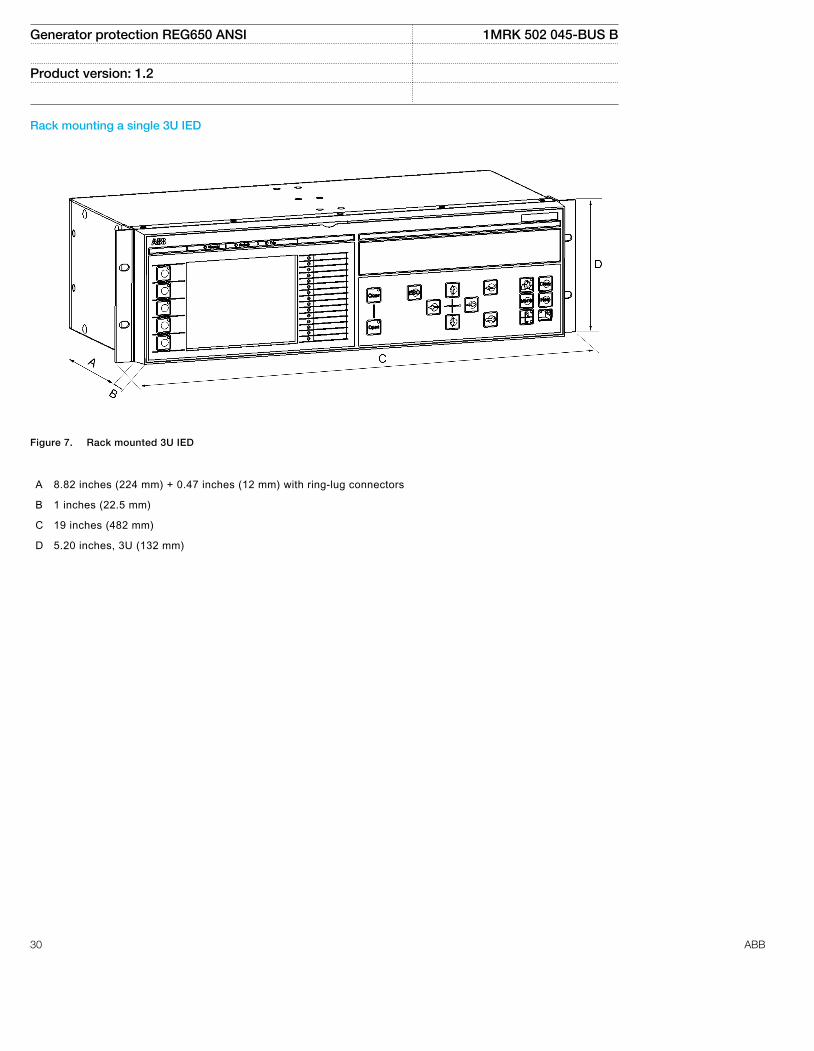
Rack mounting a single 3U IED
ANSI11000248 V1 EN
Figure 7. Rack mounted 3U IED
A 8.82 inches (224 mm) + 0.47 inches (12 mm) with ring-lug connectors
B 1 inches (22.5 mm)
C 19 inches (482 mm)
D 5.20 inches, 3U (132 mm)
Generator protection REG650 ANSI 1MRK 502 045-BUS B
Product version: 1.2
30 ABB

18. Connection diagrams Customized
Connection diagrams for 650 series
ANSI12000601 V1 EN
Figure 8. Designation for 3U, 1/1x19" casing with 1 TRM
ANSI12000602 V1 EN
Figure 9. Designation for 3U, 1/1x19" casing with 1 TRM and 1 AIM
Generator protection REG650 ANSI 1MRK 502 045-BUS B
Product version: 1.2
ABB 31

ANSI12000603 V1 EN
Figure 10. Communication module (COM)
Generator protection REG650 ANSI 1MRK 502 045-BUS B
Product version: 1.2
32 ABB

ANSI12000604 V1 EN
Figure 11. Power supply module (PSM) 48-125V DC
ANSI12000605 V1 EN
Figure 12. Power supply module (PSM) 110-250V DC, 100–240V AC
Generator protection REG650 ANSI 1MRK 502 045-BUS B
Product version: 1.2
ABB 33
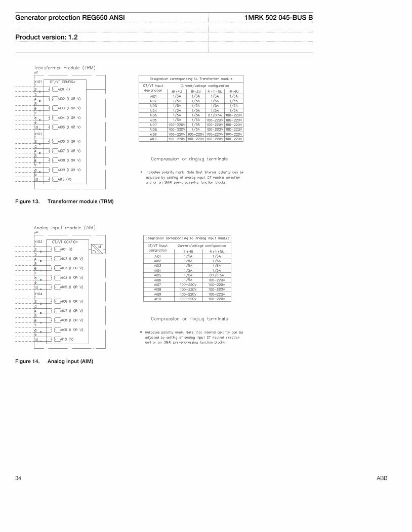
ANSI12000606 V1 EN
Figure 13. Transformer module (TRM)
ANSI12000607 V1 EN
Figure 14. Analog input (AIM)
Generator protection REG650 ANSI 1MRK 502 045-BUS B
Product version: 1.2
34 ABB
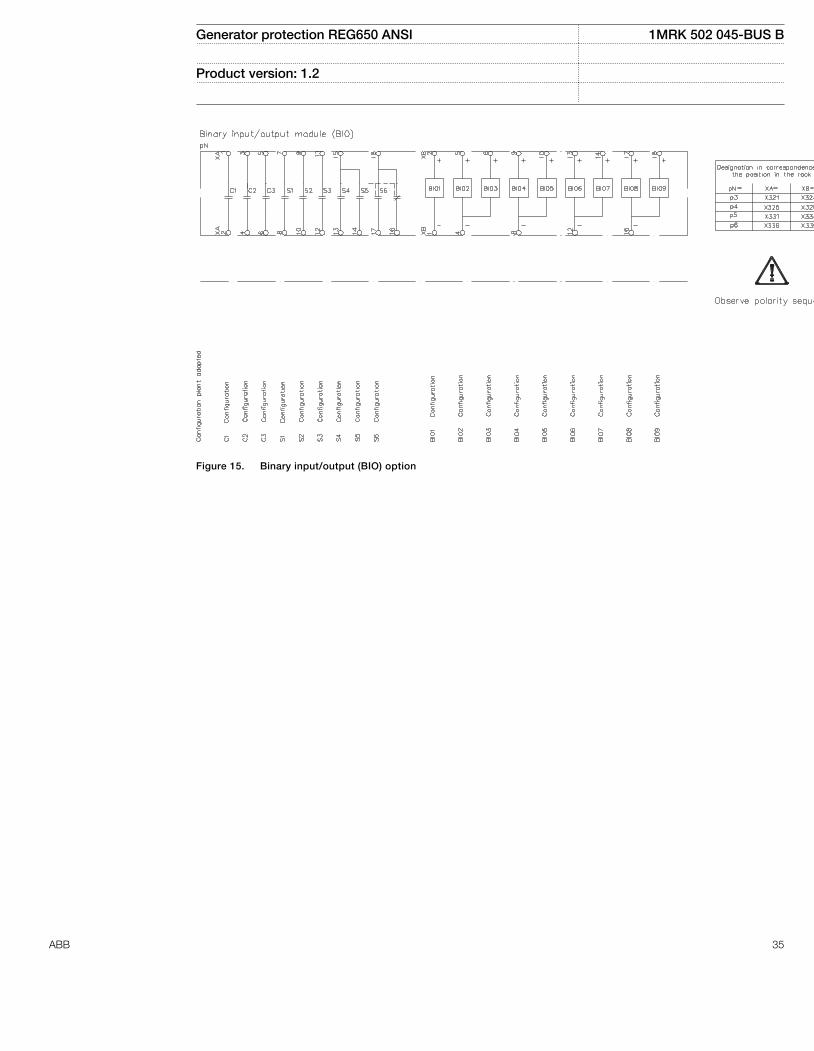
ANSI12000608 V1 EN
Figure 15. Binary input/output (BIO) option
Generator protection REG650 ANSI 1MRK 502 045-BUS B
Product version: 1.2
ABB 35
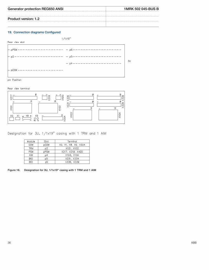
19. Connection diagrams Configured
1MRK006502-NC-3-PG-ANSI V1 EN
Figure 16. Designation for 3U, 1/1x19" casing with 1 TRM and 1 AIM
Generator protection REG650 ANSI 1MRK 502 045-BUS B
Product version: 1.2
36 ABB

Connection diagrams for REG650 B01A
1MRK006502-NC-PG-1.2-ANSI V1 EN
Figure 17. Communication module (COM)
Generator protection REG650 ANSI 1MRK 502 045-BUS B
Product version: 1.2
ABB 37
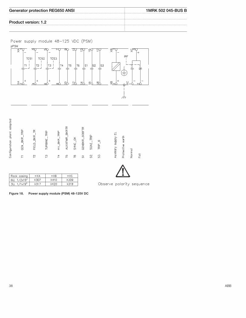
1MRK006502-NC-5-PG-1.2-ANSI V1 EN
Figure 18. Power supply module (PSM) 48-125V DC
Generator protection REG650 ANSI 1MRK 502 045-BUS B
Product version: 1.2
38 ABB

1MRK006502-NC-6-PG-1.2-ANSI V1 EN
Figure 19. Power supply module (PSM), 110-250V DC, 100–240V AC
Generator protection REG650 ANSI 1MRK 502 045-BUS B
Product version: 1.2
ABB 39
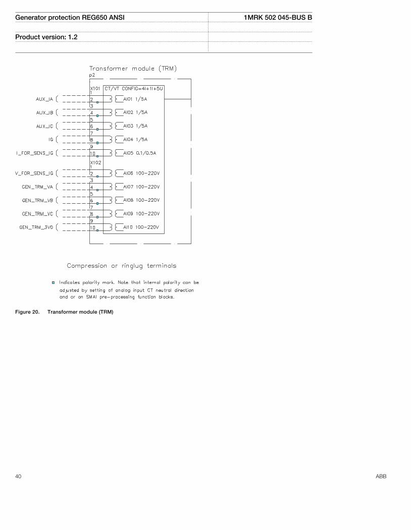
1MRK006502-NC-7-PG-1.2-ANSI V1 EN
Figure 20. Transformer module (TRM)
Generator protection REG650 ANSI 1MRK 502 045-BUS B
Product version: 1.2
40 ABB
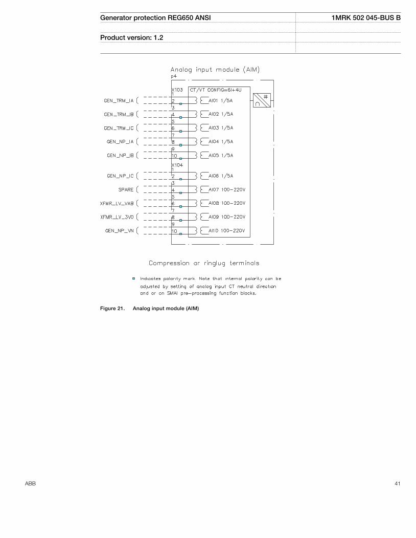
1MRK006502-NC-8-PG-1.2-ANSI V1 EN
Figure 21. Analog input module (AIM)
Generator protection REG650 ANSI 1MRK 502 045-BUS B
Product version: 1.2
ABB 41

1MRK006502-NC-9-PG-1.2-ANSI V1 EN
Figure 22. Binary input/output (BIO) option
Generator protection REG650 ANSI 1MRK 502 045-BUS B
Product version: 1.2
42 ABB

Connection diagrams for REG650 B05A
1MRK006502-PC-PG-1.2-ANSI V1 EN
Figure 23. Communication module (COM)
Generator protection REG650 ANSI 1MRK 502 045-BUS B
Product version: 1.2
ABB 43

1MRK006502-PC-5-PG-1.2-ANSI V1 EN
Figure 24. Power supply module (PSM) 48-125V DC
Generator protection REG650 ANSI 1MRK 502 045-BUS B
Product version: 1.2
44 ABB
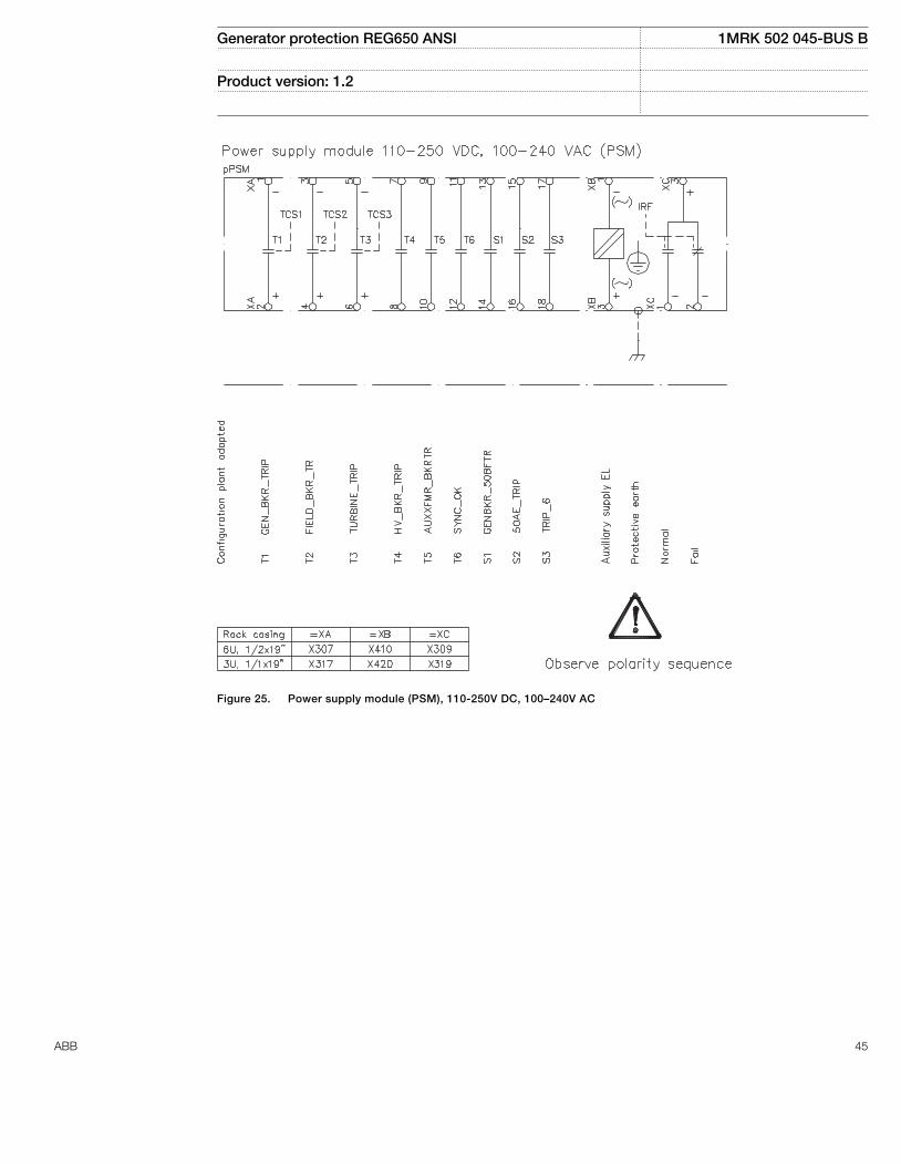
1MRK006502-PC-6-PG-1.2-ANSI V1 EN
Figure 25. Power supply module (PSM), 110-250V DC, 100–240V AC
Generator protection REG650 ANSI 1MRK 502 045-BUS B
Product version: 1.2
ABB 45
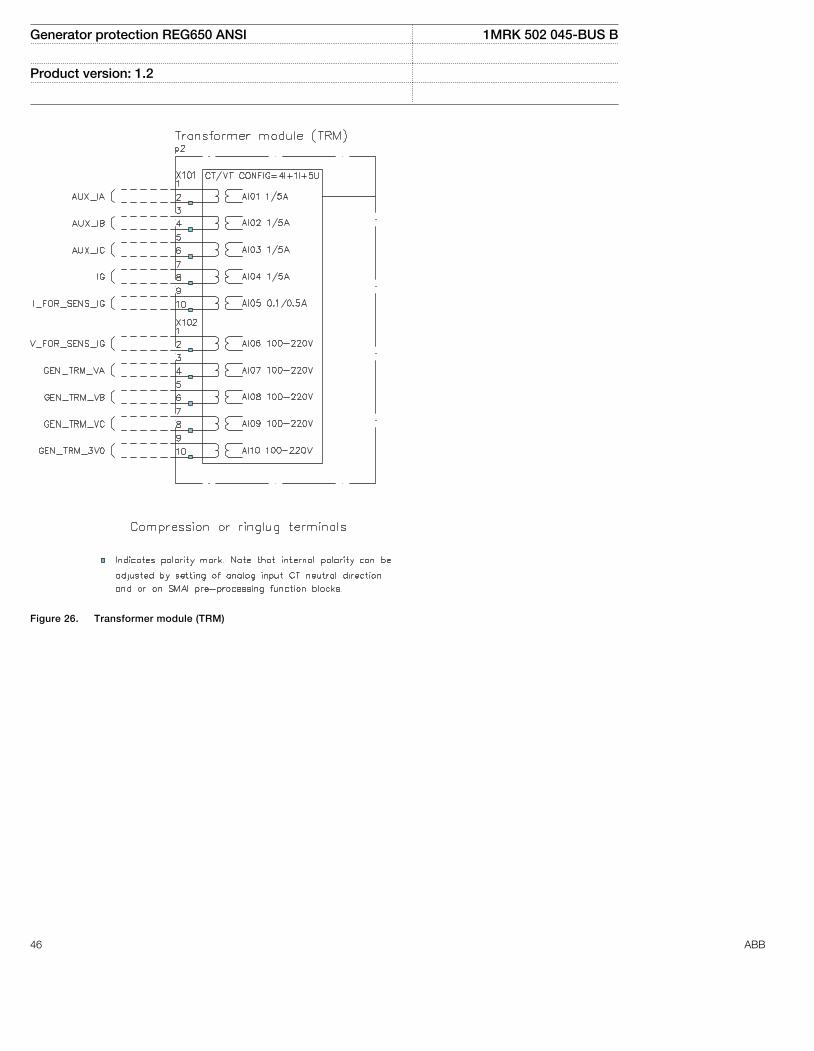
1MRK006502-PC-7-PG-1.2-ANSI V1 EN
Figure 26. Transformer module (TRM)
Generator protection REG650 ANSI 1MRK 502 045-BUS B
Product version: 1.2
46 ABB

1MRK006502-PC-8-PG-1.2-ANSI V1 EN
Figure 27. Analog input module (AIM)
Generator protection REG650 ANSI 1MRK 502 045-BUS B
Product version: 1.2
ABB 47
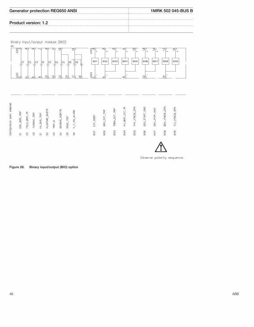
1MRK006502-PC-9-PG-1.2-ANSI V1 EN
Figure 28. Binary input/output (BIO) option
Generator protection REG650 ANSI 1MRK 502 045-BUS B
Product version: 1.2
48 ABB
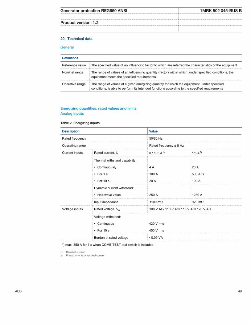
20. Technical data
General
Definitions
Reference value The specified value of an influencing factor to which are referred the characteristics of the equipment
Nominal range The range of values of an influencing quantity (factor) within which, under specified conditions, theequipment meets the specified requirements
Operative range The range of values of a given energizing quantity for which the equipment, under specifiedconditions, is able to perform its intended functions according to the specified requirements
Energizing quantities, rated values and limitsAnalog inputs
Table 2. Energizing inputs
Description Value
Rated frequency 50/60 Hz
Operating range Rated frequency ± 5 Hz
Current inputs Rated current, In 0.1/0.5 A1) 1/5 A2)
Thermal withstand capability:
• Continuously 4 A 20 A
• For 1 s 100 A 500 A *)
• For 10 s 20 A 100 A
Dynamic current withstand:
• Half-wave value 250 A 1250 A
Input impedance <100 mΩ <20 mΩ
Voltage inputs Rated voltage, Vn 100 V AC/ 110 V AC/ 115 V AC/ 120 V AC
Voltage withstand:
• Continuous 420 V rms
• For 10 s 450 V rms
Burden at rated voltage <0.05 VA
*) max. 350 A for 1 s when COMBITEST test switch is included.
1) Residual current2) Phase currents or residual current
Generator protection REG650 ANSI 1MRK 502 045-BUS B
Product version: 1.2
ABB 49
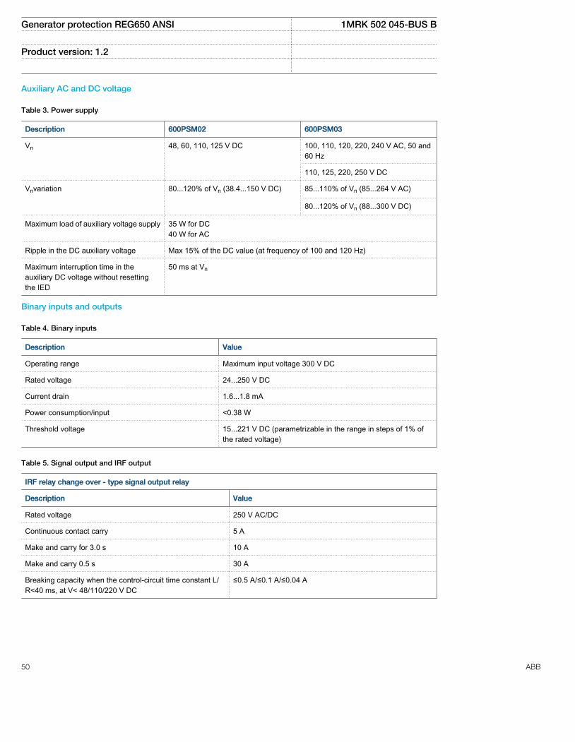
Auxiliary AC and DC voltage
Table 3. Power supply
Description 600PSM02 600PSM03
Vn 48, 60, 110, 125 V DC 100, 110, 120, 220, 240 V AC, 50 and60 Hz
110, 125, 220, 250 V DC
Vnvariation 80...120% of Vn (38.4...150 V DC) 85...110% of Vn (85...264 V AC)
80...120% of Vn (88...300 V DC)
Maximum load of auxiliary voltage supply 35 W for DC40 W for AC
Ripple in the DC auxiliary voltage Max 15% of the DC value (at frequency of 100 and 120 Hz)
Maximum interruption time in theauxiliary DC voltage without resettingthe IED
50 ms at Vn
Binary inputs and outputs
Table 4. Binary inputs
Description Value
Operating range Maximum input voltage 300 V DC
Rated voltage 24...250 V DC
Current drain 1.6...1.8 mA
Power consumption/input <0.38 W
Threshold voltage 15...221 V DC (parametrizable in the range in steps of 1% ofthe rated voltage)
Table 5. Signal output and IRF output
IRF relay change over - type signal output relay
Description Value
Rated voltage 250 V AC/DC
Continuous contact carry 5 A
Make and carry for 3.0 s 10 A
Make and carry 0.5 s 30 A
Breaking capacity when the control-circuit time constant L/R<40 ms, at V< 48/110/220 V DC
≤0.5 A/≤0.1 A/≤0.04 A
Generator protection REG650 ANSI 1MRK 502 045-BUS B
Product version: 1.2
50 ABB
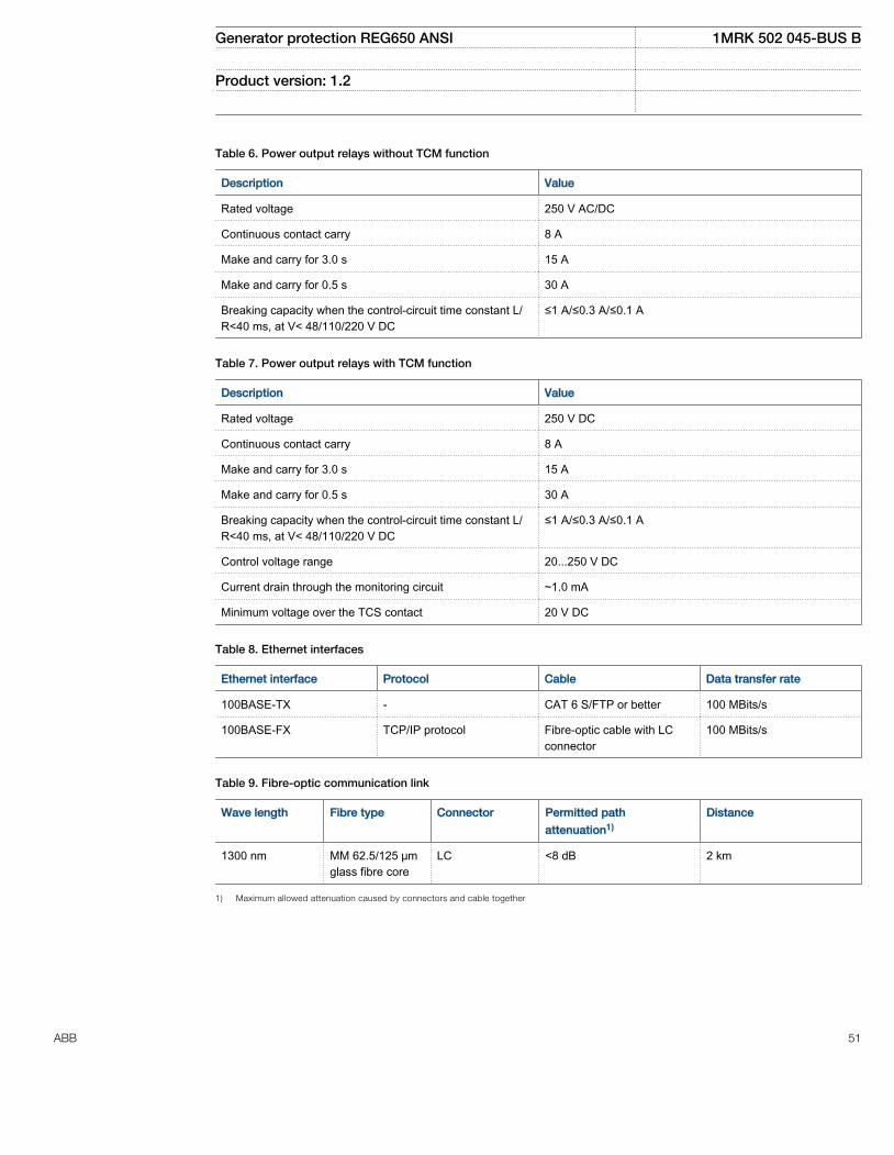
Table 6. Power output relays without TCM function
Description Value
Rated voltage 250 V AC/DC
Continuous contact carry 8 A
Make and carry for 3.0 s 15 A
Make and carry for 0.5 s 30 A
Breaking capacity when the control-circuit time constant L/R<40 ms, at V< 48/110/220 V DC
≤1 A/≤0.3 A/≤0.1 A
Table 7. Power output relays with TCM function
Description Value
Rated voltage 250 V DC
Continuous contact carry 8 A
Make and carry for 3.0 s 15 A
Make and carry for 0.5 s 30 A
Breaking capacity when the control-circuit time constant L/R<40 ms, at V< 48/110/220 V DC
≤1 A/≤0.3 A/≤0.1 A
Control voltage range 20...250 V DC
Current drain through the monitoring circuit ~1.0 mA
Minimum voltage over the TCS contact 20 V DC
Table 8. Ethernet interfaces
Ethernet interface Protocol Cable Data transfer rate
100BASE-TX - CAT 6 S/FTP or better 100 MBits/s
100BASE-FX TCP/IP protocol Fibre-optic cable with LCconnector
100 MBits/s
Table 9. Fibre-optic communication link
Wave length Fibre type Connector Permitted path
attenuation1)
Distance
1300 nm MM 62.5/125 μmglass fibre core
LC <8 dB 2 km
1) Maximum allowed attenuation caused by connectors and cable together
Generator protection REG650 ANSI 1MRK 502 045-BUS B
Product version: 1.2
ABB 51
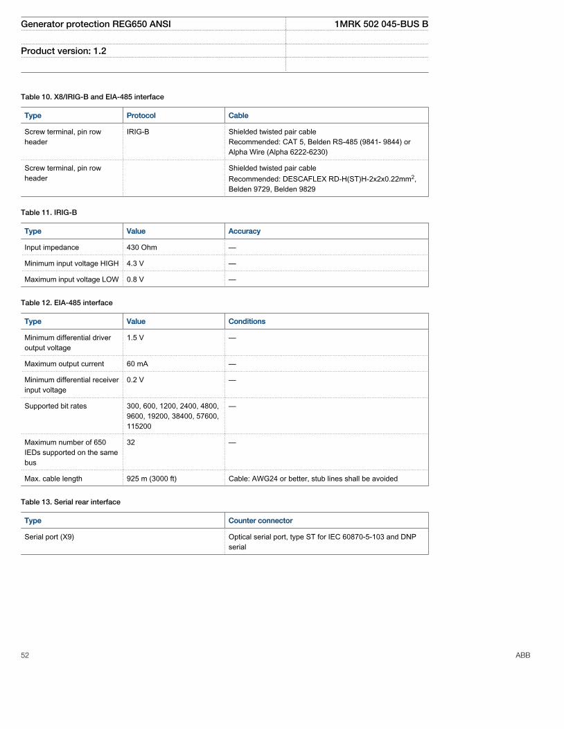
Table 10. X8/IRIG-B and EIA-485 interface
Type Protocol Cable
Screw terminal, pin rowheader
IRIG-B Shielded twisted pair cableRecommended: CAT 5, Belden RS-485 (9841- 9844) orAlpha Wire (Alpha 6222-6230)
Screw terminal, pin rowheader
Shielded twisted pair cableRecommended: DESCAFLEX RD-H(ST)H-2x2x0.22mm2,Belden 9729, Belden 9829
Table 11. IRIG-B
Type Value Accuracy
Input impedance 430 Ohm —
Minimum input voltage HIGH 4.3 V —
Maximum input voltage LOW 0.8 V —
Table 12. EIA-485 interface
Type Value Conditions
Minimum differential driveroutput voltage
1.5 V —
Maximum output current 60 mA —
Minimum differential receiverinput voltage
0.2 V —
Supported bit rates 300, 600, 1200, 2400, 4800,9600, 19200, 38400, 57600,115200
—
Maximum number of 650IEDs supported on the samebus
32 —
Max. cable length 925 m (3000 ft) Cable: AWG24 or better, stub lines shall be avoided
Table 13. Serial rear interface
Type Counter connector
Serial port (X9) Optical serial port, type ST for IEC 60870-5-103 and DNPserial
Generator protection REG650 ANSI 1MRK 502 045-BUS B
Product version: 1.2
52 ABB

Table 14. Optical serial port (X9)
Wave length Fibre type Connector Permitted path attenuation1)
820 nm MM 62,5/125 µm glassfibre core
ST 6.8 dB (approx. 1700m length with 4 db / km fibreattenuation)
820 nm MM 50/125 µm glassfibre core
ST 2.4 dB (approx. 600m length with 4 db / km fibreattenuation)
1) Maximum allowed attenuation caused by fibre
Influencing factors
Table 15. Degree of protection of rack-mounted IED
Description Value
Front side IP 40
Rear side, connection terminals IP 20
Table 16. Degree of protection of the LHMI
Description Value
Front and side IP40
Table 17. Environmental conditions
Description Value
Operating temperature range -25...+55ºC (continuous)
Short-time service temperature range -40...+70ºC (<16h)Note: Degradation in MTBF and HMI performance outsidethe temperature range of -25...+55ºC
Relative humidity <93%, non-condensing
Atmospheric pressure 12.47...15.37 psi (86...106 kPa)
Altitude up to 6561.66 feet (2000 m)
Transport and storage temperature range -40...+85ºC
Generator protection REG650 ANSI 1MRK 502 045-BUS B
Product version: 1.2
ABB 53
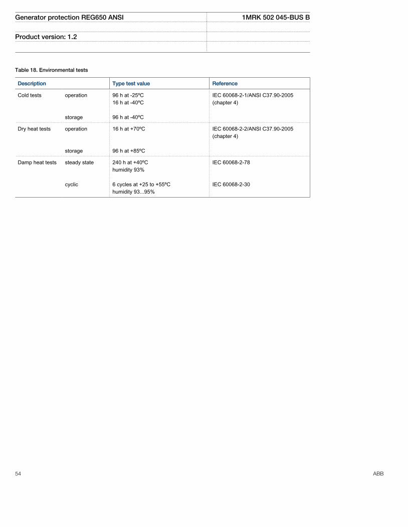
Table 18. Environmental tests
Description Type test value Reference
Cold tests operation storage
96 h at -25ºC16 h at -40ºC 96 h at -40ºC
IEC 60068-2-1/ANSI C37.90-2005(chapter 4)
Dry heat tests operation storage
16 h at +70ºC 96 h at +85ºC
IEC 60068-2-2/ANSI C37.90-2005(chapter 4)
Damp heat tests steady state cyclic
240 h at +40ºChumidity 93% 6 cycles at +25 to +55ºChumidity 93...95%
IEC 60068-2-78 IEC 60068-2-30
Generator protection REG650 ANSI 1MRK 502 045-BUS B
Product version: 1.2
54 ABB

Type tests according to standards
Table 19. Electromagnetic compatibility tests
Description Type test value Reference
100 kHz and 1 MHz burst disturbancetest
IEC 61000-4-18, level 3IEC 60255-22-1ANSI C37.90.1-2002
• Common mode 2.5 kV
• Differential mode 2.5 kV
Electrostatic discharge test IEC 61000-4-2, level 4IEC 60255-22-2ANSI C37.90.3-2001
• Contact discharge 8 kV
• Air discharge 15 kV
Radio frequency interference tests
• Conducted, common mode 10 V (emf), f=150 kHz...80 MHz IEC 61000-4-6 , level 3IEC 60255-22-6
• Radiated, amplitude-modulated 20 V/m (rms), f=80...1000 MHz andf=1.4...2.7 GHz
IEC 61000-4-3, level 3IEC 60255-22-3ANSI C37.90.2-2004
Fast transient disturbance tests IEC 61000-4-4IEC 60255-22-4, class AANSI C37.90.1-2002
• Communication ports 4 kV
• Other ports 4 kV
Surge immunity test IEC 61000-4-5, level 3/2IEC 60255-22-5
• Communication 1 kV line-to-ground
• Other ports 2 kV line-to-ground, 1 kV line-to-line
Power frequency (50 Hz) magnetic field IEC 61000-4-8, level 5
• 3 s 1000 A/m
• Continuous 100 A/m
Pulse magnetic field immunity test 1000A/m IEC 61000–4–9, level 5
Power frequency immunity test IEC 60255-22-7, class AIEC 61000-4-16
• Common mode 300 V rms
• Differential mode 150 V rms
Generator protection REG650 ANSI 1MRK 502 045-BUS B
Product version: 1.2
ABB 55

Table 19. Electromagnetic compatibility tests, continued
Description Type test value Reference
Voltage dips and short interruptionscon DC power supply
Dips:40%/200 ms70%/500 msInterruptions:0-50 ms: No restart0...∞ s : Correct behaviour at powerdown
IEC 60255-11IEC 61000-4-11
Voltage dips and interruptions on ACpower supply
Dips:40% 10/12 cycles at 50/60 Hz70% 25/30 cycles at 50/60 HzInterruptions:0–50 ms: No restart0...∞ s: Correct behaviour at power down
IEC 60255–11IEC 61000–4–11
Electromagnetic emission tests EN 55011, class AIEC 60255-25
• Conducted, RF-emission (mainsterminal)
0.15...0.50 MHz < 79 dB(µV) quasi peak< 66 dB(µV) average
0.5...30 MHz < 73 dB(µV) quasi peak< 60 dB(µV) average
• Radiated RF-emission
30...230 MHz < 40 dB(µV/m) quasi peak, measuredat 10 m distance
230...1000 MHz < 47 dB(µV/m) quasi peak, measuredat 10 m distance
Generator protection REG650 ANSI 1MRK 502 045-BUS B
Product version: 1.2
56 ABB

Table 20. Insulation tests
Description Type test value Reference
Dielectric tests: IEC 60255-5ANSI C37.90-2005
• Test voltage 2 kV, 50 Hz, 1 min1 kV, 50 Hz, 1 min, communication
Impulse voltage test: IEC 60255-5ANSI C37.90-2005
• Test voltage 5 kV, unipolar impulses, waveform1.2/50 μs, source energy 0.5 J1 kV, unipolar impulses, waveform1.2/50 μs, source energy 0.5 J,communication
Insulation resistance measurements IEC 60255-5ANSI C37.90-2005
• Isolation resistance >100 MΏ, 500 V DC
Protective bonding resistance IEC 60255-27
• Resistance <0.1 Ώ (60 s)
Table 21. Mechanical tests
Description Reference Requirement
Vibration response tests (sinusoidal) IEC 60255-21-1 Class 2
Vibration endurance test IEC60255-21-1 Class 1
Shock response test IEC 60255-21-2 Class 1
Shock withstand test IEC 60255-21-2 Class 1
Bump test IEC 60255-21-2 Class 1
Seismic test IEC 60255-21-3 Class 2
Product safety
Table 22. Product safety
Description Reference
LV directive 2006/95/EC
Standard EN 60255-27 (2005)
Generator protection REG650 ANSI 1MRK 502 045-BUS B
Product version: 1.2
ABB 57

EMC compliance
Table 23. EMC compliance
Description Reference
EMC directive 2004/108/EC
Standard EN 50263 (2000)EN 60255-26 (2007)
Generator protection REG650 ANSI 1MRK 502 045-BUS B
Product version: 1.2
58 ABB
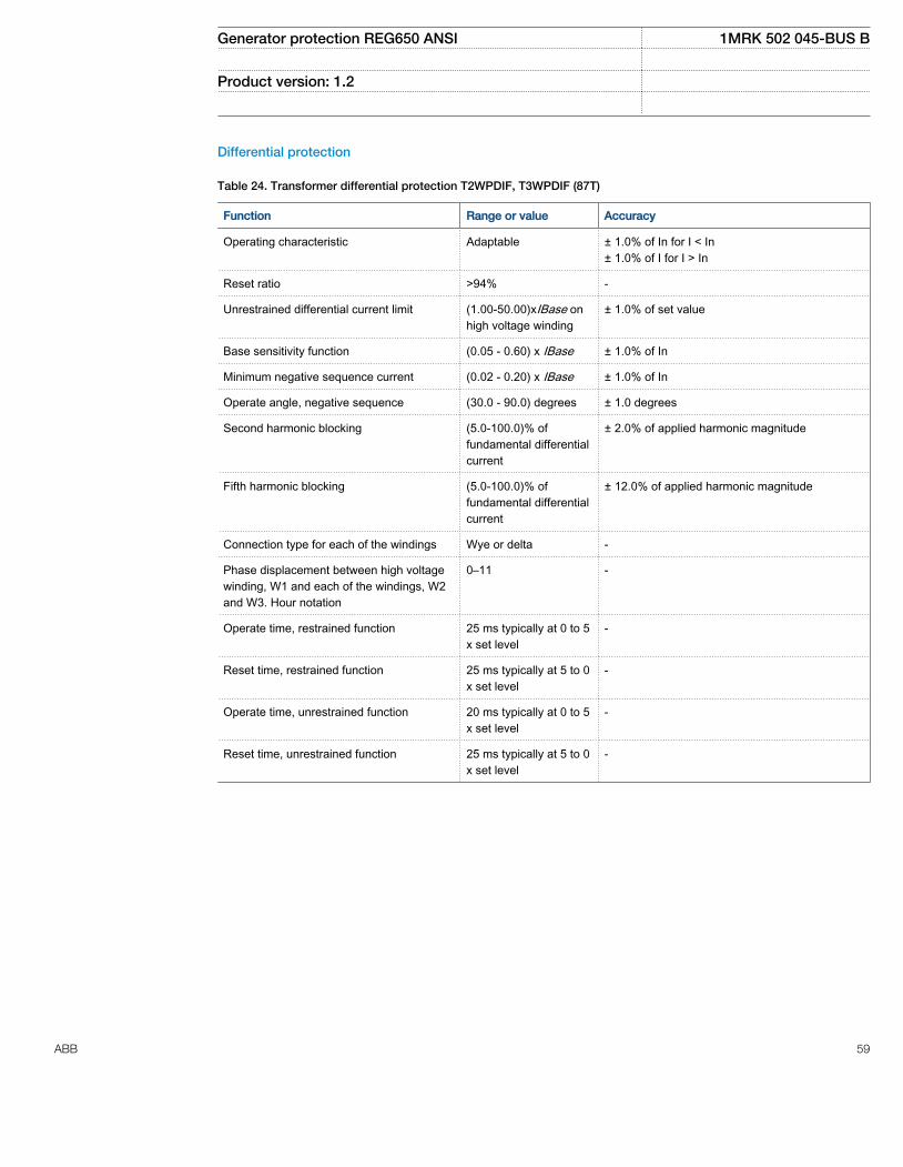
Differential protection
Table 24. Transformer differential protection T2WPDIF, T3WPDIF (87T)
Function Range or value Accuracy
Operating characteristic Adaptable ± 1.0% of In for I < In± 1.0% of I for I > In
Reset ratio >94% -
Unrestrained differential current limit (1.00-50.00)xIBase onhigh voltage winding
± 1.0% of set value
Base sensitivity function (0.05 - 0.60) x IBase ± 1.0% of In
Minimum negative sequence current (0.02 - 0.20) x IBase ± 1.0% of In
Operate angle, negative sequence (30.0 - 90.0) degrees ± 1.0 degrees
Second harmonic blocking (5.0-100.0)% offundamental differentialcurrent
± 2.0% of applied harmonic magnitude
Fifth harmonic blocking (5.0-100.0)% offundamental differentialcurrent
± 12.0% of applied harmonic magnitude
Connection type for each of the windings Wye or delta -
Phase displacement between high voltagewinding, W1 and each of the windings, W2and W3. Hour notation
0–11 -
Operate time, restrained function 25 ms typically at 0 to 5x set level
-
Reset time, restrained function 25 ms typically at 5 to 0x set level
-
Operate time, unrestrained function 20 ms typically at 0 to 5x set level
-
Reset time, unrestrained function 25 ms typically at 5 to 0x set level
-
Generator protection REG650 ANSI 1MRK 502 045-BUS B
Product version: 1.2
ABB 59
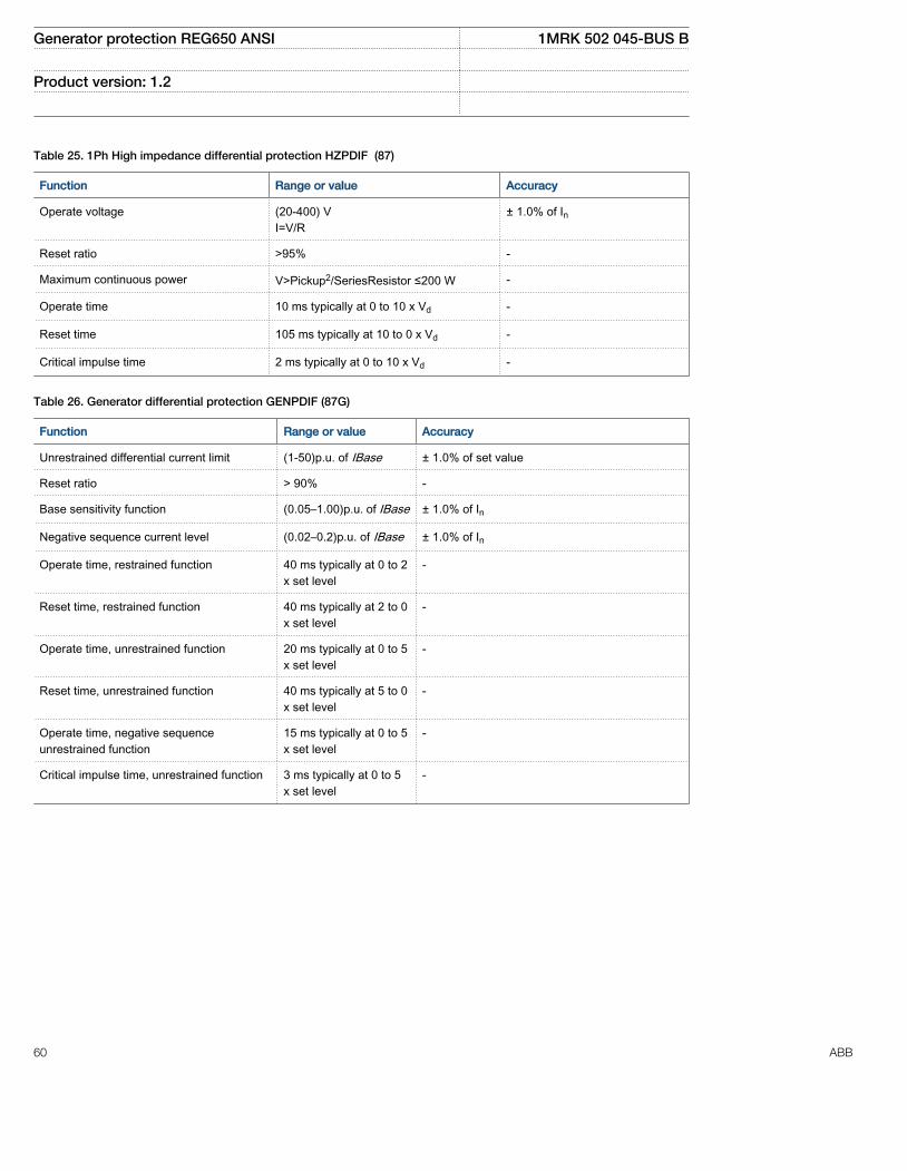
Table 25. 1Ph High impedance differential protection HZPDIF (87)
Function Range or value Accuracy
Operate voltage (20-400) VI=V/R
± 1.0% of In
Reset ratio >95% -
Maximum continuous power V>Pickup2/SeriesResistor ≤200 W -
Operate time 10 ms typically at 0 to 10 x Vd -
Reset time 105 ms typically at 10 to 0 x Vd -
Critical impulse time 2 ms typically at 0 to 10 x Vd -
Table 26. Generator differential protection GENPDIF (87G)
Function Range or value Accuracy
Unrestrained differential current limit (1-50)p.u. of IBase ± 1.0% of set value
Reset ratio > 90% -
Base sensitivity function (0.05–1.00)p.u. of IBase ± 1.0% of In
Negative sequence current level (0.02–0.2)p.u. of IBase ± 1.0% of In
Operate time, restrained function 40 ms typically at 0 to 2x set level
-
Reset time, restrained function 40 ms typically at 2 to 0x set level
-
Operate time, unrestrained function 20 ms typically at 0 to 5x set level
-
Reset time, unrestrained function 40 ms typically at 5 to 0x set level
-
Operate time, negative sequenceunrestrained function
15 ms typically at 0 to 5x set level
-
Critical impulse time, unrestrained function 3 ms typically at 0 to 5x set level
-
Generator protection REG650 ANSI 1MRK 502 045-BUS B
Product version: 1.2
60 ABB

Impedance protection
Table 27. Underimpedance protection for generators and transformers ZGCPDIS (21G)
Function Range or value Accuracy
Number of zones 3 -
Forward positive sequence impedance (0.005-3000.000) Ω/phase
± 2.0% static accuracyConditions:• Voltage range: (0.1-1.1) x Vn
• Current range: (0.5-30) x In• Angle: at 85 degrees
Reverse positive sequence impedance (0.005-3000.000) Ω/phase
-
Angle for positive sequence impedance, (10-90) degrees -
Timers (0.000-60.000) s ± 0.5% ± 10 ms
Operate time 25 ms typically -
Reset ratio 105% typically -
Table 28. Loss of excitation LEXPDIS (40)
Function Range or value Accuracy
X offset of Mho top point (–1000.00–1000.00)% of ZBase ± 2.0% of Vn/In
Diameter of Mho circle (0.00–3000.00)% of ZBase ± 2.0% of Vn/In
Timers (0.00–6000.00) s ± 0.5% ± 25 ms
Operate time 55 ms typically —
Reset ratio 105% typically —
Table 29. Out-of-step protection OOSPPAM (78)
Function Range or value Accuracy
Impedance reach (0.00–1000.00)% of Zbase ± 2.0% of Vn/In
Characteristic angle (72.00–90.00) degrees ± 5.0 degrees
Start and trip angles (0.0–180.0) degrees ± 5.0 degrees
Zone 1 and Zone 2 trip counters (1-20) -
Generator protection REG650 ANSI 1MRK 502 045-BUS B
Product version: 1.2
ABB 61

Table 30. Load enchroachment LEPDIS
Function Range or value Accuracy
Load encroachment criteria:Load resistance, forward andreverseSafety load impedance angle
(1.00–3000.00) Ω/phase(5-85) degrees
± 5.0% static accuracy± 2.0 degrees static angular accuracyConditions:Voltage range: (0.1-1.1) x Vn
Current range: (0.5-30) x In
Reset ratio 105% typically -
Current protection
Table 31. Four step phase overcurrent protection, 3-phase output OC4PTOC (51/67)
Function Setting range Accuracy
Operate current (5-2500)% of lBase ± 1.0% of In at I ≤ In± 1.0% of I at I > In
Reset ratio > 95% -
Min. operating current (1-10000)% of lBase ± 1.0% of In at I ≤ In±1.0% of I at I > In
2nd harmonic blocking (5–100)% of fundamental ± 2.0% of In
Independent time delay (0.000-60.000) s ± 0.5% ±25 ms
Minimum operate time forinverse characteristics
(0.000-60.000) s ± 0.5% ±25 ms
Inverse characteristics, seetable 72, table 73 and table 74
17 curve types 1) ANSI/IEEE C37.112IEC 60255–151±3% or ±40 ms0.10 ≤ k ≤ 3.001.5 x Iset ≤ I ≤ 20 x Iset
Operate time, nondirectionalpickup function
25 ms typically at 0 to 2 x Iset -
Reset time, pickup function 30 ms typically at 2 to 0 x Iset -
Operate time, directional pickupfunction
50 ms typically at 0 to 2 x Iset -
Reset time, directional pickupfunction
35 ms typically at 2 to 0 x Iset -
Critical impulse time 10 ms typically at 0 to 2 x Iset -
Impulse margin time 15 ms typically -
1) Note: Timing accuracy only valid when 2nd harmonic blocking is turned off
Generator protection REG650 ANSI 1MRK 502 045-BUS B
Product version: 1.2
62 ABB
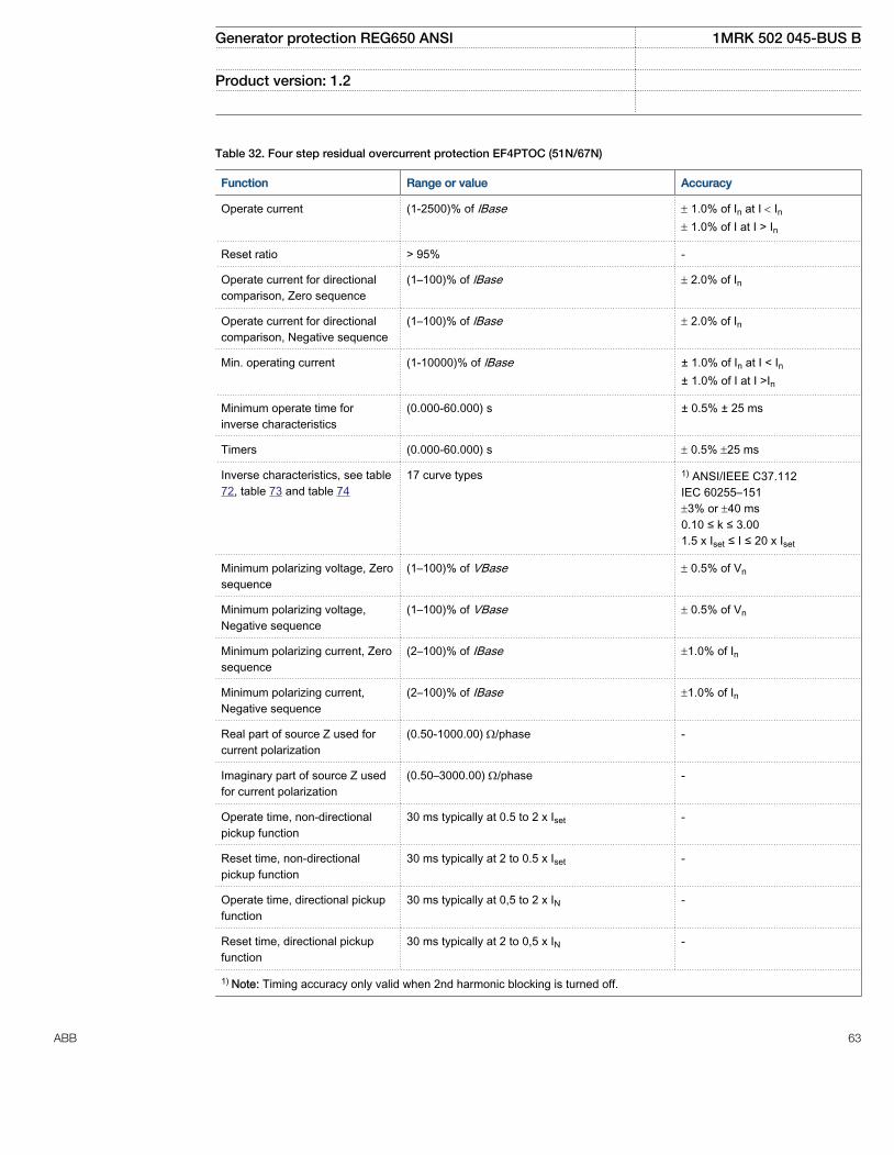
Table 32. Four step residual overcurrent protection EF4PTOC (51N/67N)
Function Range or value Accuracy
Operate current (1-2500)% of lBase ± 1.0% of In at I < In± 1.0% of I at I > In
Reset ratio > 95% -
Operate current for directionalcomparison, Zero sequence
(1–100)% of lBase ± 2.0% of In
Operate current for directionalcomparison, Negative sequence
(1–100)% of lBase ± 2.0% of In
Min. operating current (1-10000)% of lBase ± 1.0% of In at I < In± 1.0% of I at I >In
Minimum operate time forinverse characteristics
(0.000-60.000) s ± 0.5% ± 25 ms
Timers (0.000-60.000) s ± 0.5% ±25 ms
Inverse characteristics, see table72, table 73 and table 74
17 curve types 1) ANSI/IEEE C37.112IEC 60255–151±3% or ±40 ms0.10 ≤ k ≤ 3.001.5 x Iset ≤ I ≤ 20 x Iset
Minimum polarizing voltage, Zerosequence
(1–100)% of VBase ± 0.5% of Vn
Minimum polarizing voltage,Negative sequence
(1–100)% of VBase ± 0.5% of Vn
Minimum polarizing current, Zerosequence
(2–100)% of IBase ±1.0% of In
Minimum polarizing current,Negative sequence
(2–100)% of IBase ±1.0% of In
Real part of source Z used forcurrent polarization
(0.50-1000.00) W/phase -
Imaginary part of source Z usedfor current polarization
(0.50–3000.00) W/phase -
Operate time, non-directionalpickup function
30 ms typically at 0.5 to 2 x Iset -
Reset time, non-directionalpickup function
30 ms typically at 2 to 0.5 x Iset -
Operate time, directional pickupfunction
30 ms typically at 0,5 to 2 x IN -
Reset time, directional pickupfunction
30 ms typically at 2 to 0,5 x IN -
1) Note: Timing accuracy only valid when 2nd harmonic blocking is turned off.
Generator protection REG650 ANSI 1MRK 502 045-BUS B
Product version: 1.2
ABB 63
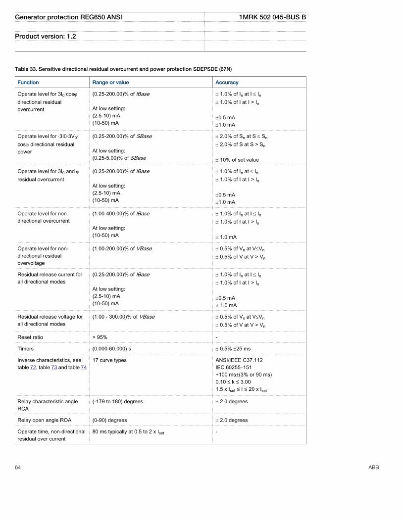
Table 33. Sensitive directional residual overcurrent and power protection SDEPSDE (67N)
Function Range or value Accuracy
Operate level for 3I0·cosj
directional residualovercurrent
(0.25-200.00)% of lBase At low setting:(2.5-10) mA(10-50) mA
± 1.0% of In at I £ In± 1.0% of I at I > In ±0.5 mA±1.0 mA
Operate level for ·3I0·3V0·cosj directional residualpower
(0.25-200.00)% of SBase At low setting:(0.25-5.00)% of SBase
± 2.0% of Sn at S £ Sn
± 2.0% of S at S > Sn
± 10% of set value
Operate level for 3I0 and jresidual overcurrent
(0.25-200.00)% of lBase At low setting:(2.5-10) mA(10-50) mA
± 1.0% of In at £ In± 1.0% of I at I > In ±0.5 mA±1.0 mA
Operate level for non-directional overcurrent
(1.00-400.00)% of lBase At low setting:(10-50) mA
± 1.0% of In at I £ In± 1.0% of I at I > In ± 1.0 mA
Operate level for non-directional residualovervoltage
(1.00-200.00)% of VBase ± 0.5% of Vn at V£Vn
± 0.5% of V at V > Vn
Residual release current forall directional modes
(0.25-200.00)% of lBase At low setting:(2.5-10) mA(10-50) mA
± 1.0% of In at I £ In± 1.0% of I at I > In ±0.5 mA± 1.0 mA
Residual release voltage forall directional modes
(1.00 - 300.00)% of VBase ± 0.5% of Vn at V£Vn
± 0.5% of V at V > Vn
Reset ratio > 95% -
Timers (0.000-60.000) s ± 0.5% ±25 ms
Inverse characteristics, seetable 72, table 73 and table 74
17 curve types ANSI/IEEE C37.112IEC 60255–151+100 ms±(3% or 90 ms)0.10 ≤ k ≤ 3.001.5 x Iset ≤ I ≤ 20 x Iset
Relay characteristic angleRCA
(-179 to 180) degrees ± 2.0 degrees
Relay open angle ROA (0-90) degrees ± 2.0 degrees
Operate time, non-directionalresidual over current
80 ms typically at 0.5 to 2 x Iset -
Generator protection REG650 ANSI 1MRK 502 045-BUS B
Product version: 1.2
64 ABB

Table 33. Sensitive directional residual overcurrent and power protection SDEPSDE (67N) , continued
Function Range or value Accuracy
Reset time, non-directionalresidual over current
90 ms typically at 1.2 to 0.5 x Iset -
Operate time, non-directionalresidual overvoltage
70 ms typically at 0.8 to 1.5 x Uset -
Reset time, non-directionalresidual overvoltage
120 ms typically at 1.2 to 0.8 x Uset -
Operate time, directionalresidual over current
260 ms typically at 0.5 to 2 x Iset -
Reset time, directionalresidual over current
170 ms typically at 2 to 0.5 x Iset -
Critical impulse time non-directional residual overcurrent
100 ms typically at 0 to 2 x Iset
20 ms typically at 0 to 10 x Iset
--
Impulse margin time non-directional residual overcurrent
25 ms typically -
Table 34. Thermal overload protection, two time constants TRPTTR (49)
Function Range or value Accuracy
Base current 1 and 2 (30–250)% of IBase ± 1.0% of In
Operate time:
2 2
2 2ln p
b
I It
I It
æ ö-ç ÷= ×ç ÷-è ø
EQUATION1356 V1 EN (Equation 1)
I = Imeasured
Ip = load current before overloadoccursTime constant τ = (1–500)minutes
IEC 60255–8, ±5% + 200 ms
Alarm pickup 1 and 2 (50–99)% of heat content tripvalue
± 2.0% of heat content trip
Operate current (50–250)% of IBase ± 1.0% of In
Reset level temperature (10–95)% of heat content trip ± 2.0% of heat content trip
Generator protection REG650 ANSI 1MRK 502 045-BUS B
Product version: 1.2
ABB 65

Table 35. Breaker failure protection, 3-phase activation and output CCRBRF (50BF)
Function Range or value Accuracy
Operate phase current (5-200)% of lBase ± 1.0% of In at I £ In± 1.0% of I at I > In
Reset ratio, phase current > 95% -
Operate residual current (2-200)% of lBase ± 1.0% of In at I £ In± 1.0% of I at I > In
Reset ratio, residual current > 95% -
Phase current pickup for blocking ofcontact function
(5-200)% of lBase ± 1.0% of In at I £ In± 1.0% of I at I > In
Reset ratio > 95% -
Timers (0.000-60.000) s ± 0.5% ±10 ms
Operate time for current detection 35 ms typically -
Reset time for current detection 10 ms maximum -
Table 36. Pole discrepancy protection CCRPLD (52PD)
Function Range or value Accuracy
Operate value, currentasymmetry level
(0-100) % ± 1.0% of In
Reset ratio >95% -
Time delay (0.000-60.000) s ± 0.5% ± 25 ms
Table 37. Directional over/underpower protection GOPPDOP, GUPPDUP (32/37)
Function Range or value Accuracy
Power level (0.0–500.0)% of SBase ± 1.0% of Sr at S < Sr
± 1.0% of S at S > Sr
(1.0-2.0)% of SBase < ± 50% of set value
(2.0-10)% of SBase < ± 20% of set value
Characteristic angle (-180.0–180.0) degrees 2 degrees
Timers (0.010 - 6000.000) s ± 0.5% ± 25 ms
Generator protection REG650 ANSI 1MRK 502 045-BUS B
Product version: 1.2
66 ABB

Table 38. Accidental energizing protection for synchronous generator AEGGAPC (50AE)
Function Range or value Accuracy
Operate value, overcurrent (2-900)% of IBase ± 1,0% of In at I<In± 1.0% of I at I>In
Reset ratio, overcurrent >95% -
Transient overreach, overcurrent function <20% at τ = 100 ms -
Critical impulse time, overcurrent 10 ms typically at 0 to 2 x Iset -
Impulse margin time, overcurrent 15 ms typically -
Operate value, undervoltage (2-200)% of VBase ± 0.5% of Vn at V<Vn
± 0.5% of V at V>Vn
Critical impulse time, undervoltage 10 ms typically at 2 to 0 x Vset -
Impulse margin time, undervoltage 15 ms typically -
Operate value, overvoltage (2-200)% of VBase ± 0.5% of Vn at V<Vn
± 0.5% of V at V>Vn
Timers (0.000-60.000) s ± 0.5% ± 25 ms
Table 39. Negative sequence time overcurrent protection for machines NS2PTOC (46I2)
Function Range or value Accuracy
Operate value, step 1 and 2, negativesequence overcurrent
(3-500)% of IBase ± 1.0% of In at I < In± 1.0% of I at I > In
Reset ratio, step 1 and 2 >95% -
Operate time, pickup 30 ms typically at 0 to 2 x Iset
20 ms typically at 0 to 10 x Iset
-
Reset time, pickup 40 ms typically at 2 to 0 x Iset -
Time characteristics Definite or Inverse -
Inverse time characteristic step 1,2
2I t K=
K=1.0-99.0 ± 3% or ± 40 ms1 ≤ K ≤ 20
Reset time, inverse characteristic step 1,2
2I t K=
K=0.01-20.00 ± 10% or ± 50 ms1 ≤ K ≤ 20
Maximum trip delay, step 1 IDMT (0.00-6000.00) s ± 0.5% ± 25 ms
Minimum trip delay, step 1 IDMT (0.000-60.000) s ± 0.5% ± 25 ms
Timers (0.00-6000.00) s ± 0.5% ± 25 ms
Generator protection REG650 ANSI 1MRK 502 045-BUS B
Product version: 1.2
ABB 67
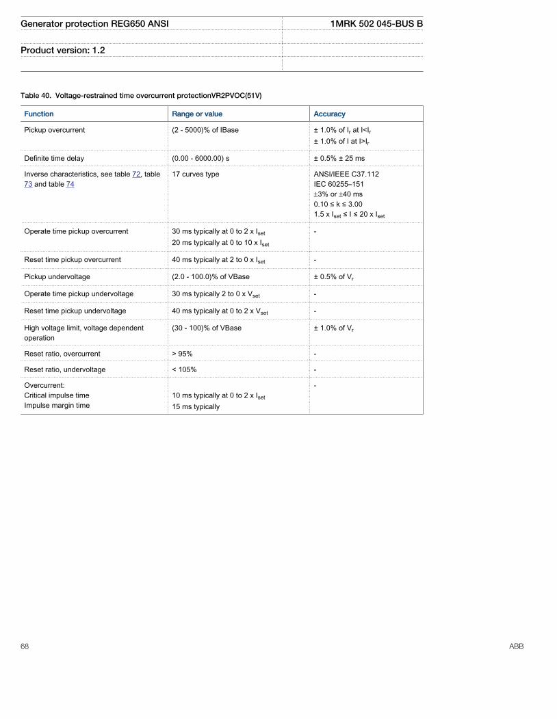
Table 40. Voltage-restrained time overcurrent protectionVR2PVOC(51V)
Function Range or value Accuracy
Pickup overcurrent (2 - 5000)% of IBase ± 1.0% of Ir at I<Ir± 1.0% of I at I>Ir
Definite time delay (0.00 - 6000.00) s ± 0.5% ± 25 ms
Inverse characteristics, see table 72, table73 and table 74
17 curves type ANSI/IEEE C37.112IEC 60255–151±3% or ±40 ms0.10 ≤ k ≤ 3.001.5 x Iset ≤ I ≤ 20 x Iset
Operate time pickup overcurrent 30 ms typically at 0 to 2 x Iset
20 ms typically at 0 to 10 x Iset
-
Reset time pickup overcurrent 40 ms typically at 2 to 0 x Iset -
Pickup undervoltage (2.0 - 100.0)% of VBase ± 0.5% of Vr
Operate time pickup undervoltage 30 ms typically 2 to 0 x Vset -
Reset time pickup undervoltage 40 ms typically at 0 to 2 x Vset -
High voltage limit, voltage dependentoperation
(30 - 100)% of VBase ± 1.0% of Vr
Reset ratio, overcurrent > 95% -
Reset ratio, undervoltage < 105% -
Overcurrent:Critical impulse timeImpulse margin time
10 ms typically at 0 to 2 x Iset
15 ms typically
-
Generator protection REG650 ANSI 1MRK 502 045-BUS B
Product version: 1.2
68 ABB
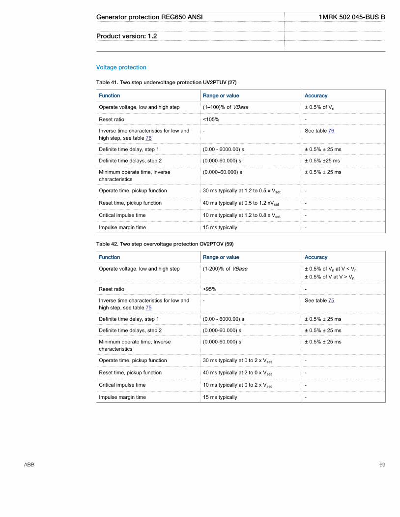
Voltage protection
Table 41. Two step undervoltage protection UV2PTUV (27)
Function Range or value Accuracy
Operate voltage, low and high step (1–100)% of VBase ± 0.5% of Vn
Reset ratio <105% -
Inverse time characteristics for low andhigh step, see table 76
- See table 76
Definite time delay, step 1 (0.00 - 6000.00) s ± 0.5% ± 25 ms
Definite time delays, step 2 (0.000-60.000) s ± 0.5% ±25 ms
Minimum operate time, inversecharacteristics
(0.000–60.000) s ± 0.5% ± 25 ms
Operate time, pickup function 30 ms typically at 1.2 to 0.5 x Vset -
Reset time, pickup function 40 ms typically at 0.5 to 1.2 xVset -
Critical impulse time 10 ms typically at 1.2 to 0.8 x Vset -
Impulse margin time 15 ms typically -
Table 42. Two step overvoltage protection OV2PTOV (59)
Function Range or value Accuracy
Operate voltage, low and high step (1-200)% of VBase ± 0.5% of Vn at V < Vn
± 0.5% of V at V > Vn
Reset ratio >95% -
Inverse time characteristics for low andhigh step, see table 75
- See table 75
Definite time delay, step 1 (0.00 - 6000.00) s ± 0.5% ± 25 ms
Definite time delays, step 2 (0.000-60.000) s ± 0.5% ± 25 ms
Minimum operate time, Inversecharacteristics
(0.000-60.000) s ± 0.5% ± 25 ms
Operate time, pickup function 30 ms typically at 0 to 2 x Vset -
Reset time, pickup function 40 ms typically at 2 to 0 x Vset -
Critical impulse time 10 ms typically at 0 to 2 x Vset -
Impulse margin time 15 ms typically -
Generator protection REG650 ANSI 1MRK 502 045-BUS B
Product version: 1.2
ABB 69

Table 43. Two step residual overvoltage protection ROV2PTOV (59N)
Function Range or value Accuracy
Operate voltage, step 1 (1-200)% of VBase ± 0.5% of Vn at V < Vn
± 0.5% of V at V > Vn
Operate voltage, step 2 (1–100)% of VBase ± 0.5% of Vn at V < Vn
± 0.5% of V at V > Vn
Reset ratio >95% -
Inverse time characteristics for low andhigh step, see table 77
- See table 77
Definite time setting, step 1 (0.00–6000.00) s ± 0.5% ± 25 ms
Definite time setting, step 2 (0.000–60.000) s ± 0.5% ± 25 ms
Minimum operate time for step 1 inversecharacteristic
(0.000-60.000) s ± 0.5% ± 25 ms
Operate time, pickup function 30 ms typically at 0 to 2 x Vset -
Reset time, pickup function 40 ms typically at 2 to 0 x Vset -
Critical impulse time 10 ms typically at 0 to 1.2 xVset -
Impulse margin time 15 ms typically -
Table 44. Overexcitation protection OEXPVPH (24)
Function Range or value Accuracy
Pickup value, pickup (100–180)% of (VBase/fn) ± 0.5% of V
Pickup value, alarm (50–120)% of pickup level ± 0.5% of Vn at V ≤ Vn
± 0.5% of V at V > Vn
Pickup value, high level (100–200)% of (VBase/fn) ± 0.5% of V
Curve type IEEE
2
(0.18 ):
( 1)×
=-
TDIEEE t
M
EQUATION1645 V1 EN (Equation 2)
where M = (E/f)/(Vn/fn)
± 5% + 40 ms
Minimum time delay for inversefunction
(0.000–60.000) s ± 0.5% ± 25 ms
Alarm time delay (0.000–60.000) s ± 0.5% ± 25 ms
Generator protection REG650 ANSI 1MRK 502 045-BUS B
Product version: 1.2
70 ABB

Table 45. 100% Stator E/F 3rd harmonic STEFPHIZ (59THD)
Function Range or value Accuracy
Fundamental frequency level UN(95% Stator EF)
(1.0–50.0)% of VBase ± 0.5% of Vn
Third harmonic differential level (0.5–10.0)% of VBase ± 5.0% of Vn
Third harmonic differential blocklevel
(0.1–10.0)% of VBase ± 5.0% of Vn
Timers (0.020–60.000) s ± 0.5% ± 25 ms
Filter characteristic:FundamentalThird harmonic
Reject third harmonic by 1–40Reject fundamental harmonic by1–40
-
Frequency protection
Table 46. Under frequency protection SAPTUF (81)
Function Range or value Accuracy
Operate value, pickup function (35.00-75.00) Hz ± 2.0 mHz
Operate value, restore frequency (45 - 65) Hz ± 2.0 mHz
Reset ratio <1.001 -
Operate time, pickup function At 50 Hz: 200 ms typically at fset +0.5 Hz tofset -0.5 HzAt 60 Hz: 170 ms typically at fset +0.5 Hz tofset -0.5 Hz
-
Reset time, pickup function At 50 Hz: 60 ms typically at fset -0.5 Hz to fset
+0.5 HzAt 60 Hz: 50 ms typically at fset -0.5 Hz to fset
+0.5 Hz
-
Operate time delay (0.000-60.000)s <250 ms
Restore time delay (0.000-60.000)s <150 ms
Generator protection REG650 ANSI 1MRK 502 045-BUS B
Product version: 1.2
ABB 71
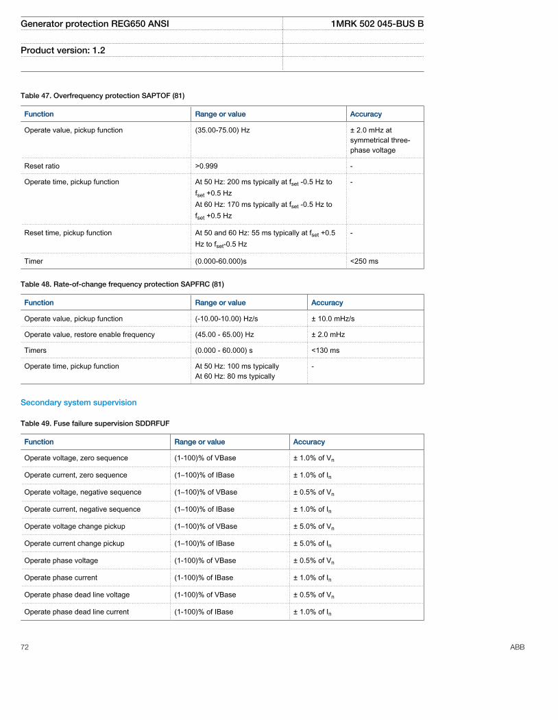
Table 47. Overfrequency protection SAPTOF (81)
Function Range or value Accuracy
Operate value, pickup function (35.00-75.00) Hz ± 2.0 mHz atsymmetrical three-phase voltage
Reset ratio >0.999 -
Operate time, pickup function At 50 Hz: 200 ms typically at fset -0.5 Hz tofset +0.5 HzAt 60 Hz: 170 ms typically at fset -0.5 Hz tofset +0.5 Hz
-
Reset time, pickup function At 50 and 60 Hz: 55 ms typically at fset +0.5Hz to fset-0.5 Hz
-
Timer (0.000-60.000)s <250 ms
Table 48. Rate-of-change frequency protection SAPFRC (81)
Function Range or value Accuracy
Operate value, pickup function (-10.00-10.00) Hz/s ± 10.0 mHz/s
Operate value, restore enable frequency (45.00 - 65.00) Hz ± 2.0 mHz
Timers (0.000 - 60.000) s <130 ms
Operate time, pickup function At 50 Hz: 100 ms typicallyAt 60 Hz: 80 ms typically
-
Secondary system supervision
Table 49. Fuse failure supervision SDDRFUF
Function Range or value Accuracy
Operate voltage, zero sequence (1-100)% of VBase ± 1.0% of Vn
Operate current, zero sequence (1–100)% of IBase ± 1.0% of In
Operate voltage, negative sequence (1–100)% of VBase ± 0.5% of Vn
Operate current, negative sequence (1–100)% of IBase ± 1.0% of In
Operate voltage change pickup (1–100)% of VBase ± 5.0% of Vn
Operate current change pickup (1–100)% of IBase ± 5.0% of In
Operate phase voltage (1-100)% of VBase ± 0.5% of Vn
Operate phase current (1-100)% of IBase ± 1.0% of In
Operate phase dead line voltage (1-100)% of VBase ± 0.5% of Vn
Operate phase dead line current (1-100)% of IBase ± 1.0% of In
Generator protection REG650 ANSI 1MRK 502 045-BUS B
Product version: 1.2
72 ABB

Table 50. Breaker close/trip circuit monitoring TCSSCBR
Function Range or value Accuracy
Operate time delay (0.020 - 300.000) s ± 0,5% ± 110 ms
Generator protection REG650 ANSI 1MRK 502 045-BUS B
Product version: 1.2
ABB 73
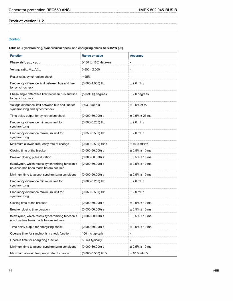
Control
Table 51. Synchronizing, synchronism check and energizing check SESRSYN (25)
Function Range or value Accuracy
Phase shift, jline - jbus (-180 to 180) degrees -
Voltage ratio, Vbus/Vline 0.500 - 2.000 -
Reset ratio, synchronism check > 95% -
Frequency difference limit between bus and linefor synchrocheck
(0.003-1.000) Hz ± 2.0 mHz
Phase angle difference limit between bus and linefor synchrocheck
(5.0-90.0) degrees ± 2.0 degrees
Voltage difference limit between bus and line forsynchronizing and synchrocheck
0.03-0.50 p.u ± 0.5% of Vn
Time delay output for synchronism check (0.000-60.000) s ± 0.5% ± 25 ms
Frequency difference minimum limit forsynchronizing
(0.003-0.250) Hz ± 2.0 mHz
Frequency difference maximum limit forsynchronizing
(0.050-0.500) Hz ± 2.0 mHz
Maximum allowed frequency rate of change (0.000-0.500) Hz/s ± 10.0 mHz/s
Closing time of the breaker (0.000-60.000) s ± 0.5% ± 10 ms
Breaker closing pulse duration (0.000-60.000) s ± 0.5% ± 10 ms
tMaxSynch, which resets synchronizing function ifno close has been made before set time
(0.000-60.000) s ± 0.5% ± 10 ms
Minimum time to accept synchronizing conditions (0.000-60.000) s ± 0.5% ± 10 ms
Frequency difference minimum limit forsynchronizing
(0.003-0.250) Hz ± 2.0 mHz
Frequency difference maximum limit forsynchronizing
(0.050-0.500) Hz ± 2.0 mHz
Closing time of the breaker (0.000-60.000) s ± 0.5% ± 10 ms
Breaker closing time duration (0.050-60.000) s ± 0.5% ± 10 ms
tMaxSynch, which resets synchronizing function ifno close has been made before set time
(0.00-6000.00) s ± 0.5% ± 10 ms
Time delay output for energizing check (0.000-60.000) s ± 0.5% ± 10 ms
Operate time for synchronism check function 160 ms typically -
Operate time for energizing function 80 ms typically -
Minimum time to accept synchronizing conditions (0.000-60.000) s ± 0.5% ± 10 ms
Maximum allowed frequency rate of change (0.000-0.500) Hz/s ± 10.0 mHz/s
Generator protection REG650 ANSI 1MRK 502 045-BUS B
Product version: 1.2
74 ABB
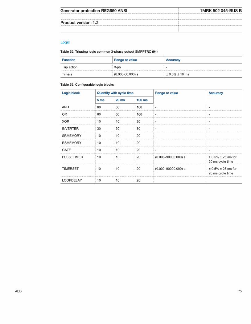
Logic
Table 52. Tripping logic common 3-phase output SMPPTRC (94)
Function Range or value Accuracy
Trip action 3-ph -
Timers (0.000-60.000) s ± 0.5% ± 10 ms
Table 53. Configurable logic blocks
Logic block Quantity with cycle time Range or value Accuracy
5 ms 20 ms 100 ms
AND 60 60 160 - -
OR 60 60 160 - -
XOR 10 10 20 - -
INVERTER 30 30 80 - -
SRMEMORY 10 10 20 - -
RSMEMORY 10 10 20 - -
GATE 10 10 20 - -
PULSETIMER 10 10 20 (0.000–90000.000) s ± 0.5% ± 25 ms for20 ms cycle time
TIMERSET 10 10 20 (0.000–90000.000) s ± 0.5% ± 25 ms for20 ms cycle time
LOOPDELAY 10 10 20
Generator protection REG650 ANSI 1MRK 502 045-BUS B
Product version: 1.2
ABB 75
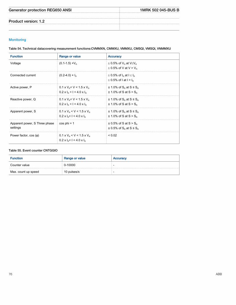
Monitoring
Table 54. Technical datacovering measurement functions:CVMMXN, CMMXU, VMMXU, CMSQI, VMSQI, VNMMXU
Function Range or value Accuracy
Voltage (0.1-1.5) ×Vn ± 0.5% of Vn at V£Vn
± 0.5% of V at V > Vn
Connected current (0.2-4.0) × In ± 0.5% of In at I £ In± 0.5% of I at I > In
Active power, P 0.1 x Vn< V < 1.5 x Vn
0.2 x In < I < 4.0 x In± 1.0% of Sn at S ≤ Sn
± 1.0% of S at S > Sn
Reactive power, Q 0.1 x Vn< V < 1.5 x Vn
0.2 x In < I < 4.0 x In± 1.0% of Sn at S ≤ Sn
± 1.0% of S at S > Sn
Apparent power, S 0.1 x Vn < V < 1.5 x Vn
0.2 x In< I < 4.0 x In± 1.0% of Sn at S ≤ Sn
± 1.0% of S at S > Sn
Apparent power, S Three phasesettings
cos phi = 1 ± 0.5% of S at S > Sn
± 0.5% of Sn at S ≤ Sn
Power factor, cos (φ) 0.1 x Vn < V < 1.5 x Vn
0.2 x In< I < 4.0 x In< 0.02
Table 55. Event counter CNTGGIO
Function Range or value Accuracy
Counter value 0-10000 -
Max. count up speed 10 pulses/s -
Generator protection REG650 ANSI 1MRK 502 045-BUS B
Product version: 1.2
76 ABB

Table 56. Disturbance report DRPRDRE
Function Range or value Accuracy
Current recording - ± 1,0% of Ir at I ≤ Ir± 1,0% of I at I > Ir
Voltage recording - ± 1,0% of Vn at V≤ Vn
± 1,0% of Vat V> Vn
Pre-fault time (0.05–3.00) s -
Post-fault time (0.1–10.0) s -
Limit time (0.5–8.0) s -
Maximum number of recordings 100, first in - first out -
Time tagging resolution 1 ms See time synchronizationtechnical data
Maximum number of analog inputs 30 + 10 (external + internallyderived)
-
Maximum number of binary inputs 96 -
Maximum number of phasors in the Trip Value recorderper recording
30 -
Maximum number of indications in a disturbance report 96 -
Maximum number of events in the Event recording perrecording
150 -
Maximum number of events in the Sequence of events 1000, first in - first out -
Maximum total recording time (3.4 s recording time andmaximum number of channels, typical value)
340 seconds (100 recordings) at50 Hz, 280 seconds (80recordings) at 60 Hz
-
Sampling rate 1 kHz at 50 Hz1.2 kHz at 60 Hz
-
Recording bandwidth (5-300) Hz -
Table 57. Event list DRPRDRE
Function Value
Buffer capacity Maximum number of events in the list 1000
Resolution 1 ms
Accuracy Depending on time synchronizing
Generator protection REG650 ANSI 1MRK 502 045-BUS B
Product version: 1.2
ABB 77
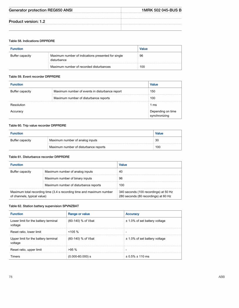
Table 58. Indications DRPRDRE
Function Value
Buffer capacity Maximum number of indications presented for singledisturbance
96
Maximum number of recorded disturbances 100
Table 59. Event recorder DRPRDRE
Function Value
Buffer capacity Maximum number of events in disturbance report 150
Maximum number of disturbance reports 100
Resolution 1 ms
Accuracy Depending on timesynchronizing
Table 60. Trip value recorder DRPRDRE
Function Value
Buffer capacity
Maximum number of analog inputs 30
Maximum number of disturbance reports 100
Table 61. Disturbance recorder DRPRDRE
Function Value
Buffer capacity Maximum number of analog inputs 40
Maximum number of binary inputs 96
Maximum number of disturbance reports 100
Maximum total recording time (3.4 s recording time and maximum numberof channels, typical value)
340 seconds (100 recordings) at 50 Hz280 seconds (80 recordings) at 60 Hz
Table 62. Station battery supervision SPVNZBAT
Function Range or value Accuracy
Lower limit for the battery terminalvoltage
(60-140) % of Vbat ± 1.0% of set battery voltage
Reset ratio, lower limit <105 % -
Upper limit for the battery terminalvoltage
(60-140) % of Vbat ± 1.0% of set battery voltage
Reset ratio, upper limit >95 % -
Timers (0.000-60.000) s ± 0.5% ± 110 ms
Generator protection REG650 ANSI 1MRK 502 045-BUS B
Product version: 1.2
78 ABB

Table 63. Insulation gas monitoring function SSIMG (63)
Function Range or value Accuracy
Pressure alarm 0.00-25.00 -
Pressure lockout 0.00-25.00 -
Temperature alarm -40.00-200.00 -
Temperature lockout -40.00-200.00 -
Timers (0.000-60.000) s ± 0.5% ± 110 ms
Table 64. Insulation liquid monitoring function SSIML(71)
Function Range or value Accuracy
Alarm, oil level 0.00-25.00 -
Oil level lockout 0.00-25.00 -
Temperature alarm -40.00-200.00 -
Temperature lockout -40.00-200.00 -
Timers (0.000-60.000) s ± 0.5% ± 110 ms
Table 65. Circuit breaker condition monitoring SSCBR
Function Range or value Accuracy
Alarm levels for open and close traveltime
(0-200) ms ± 0.5% ± 25 ms
Alarm levels for number of operations (0 - 9999) -
Setting of alarm for spring charging time (0.00-60.00) s ± 0.5% ± 25 ms
Time delay for gas pressure alarm (0.00-60.00) s ± 0.5% ± 25 ms
Time delay for gas pressure lockout (0.00-60.00) s ± 0.5% ± 25 ms
Metering
Table 66. Pulse counter PCGGIO
Function Setting range Accuracy
Cycle time for report of countervalue
(1–3600) s -
Table 67. Function for energy calculation and demand handling ETPMMTR
Function Range or value Accuracy
Energy metering MWh Export/Import, MVArhExport/Import
Input from MMXU. No extra error at steady load
Generator protection REG650 ANSI 1MRK 502 045-BUS B
Product version: 1.2
ABB 79

Station communication
Table 68. Communication protocol
Function Value
Protocol TCP/IP Ethernet
Communication speed for the IEDs 100 Mbit/s
Protocol IEC 61850–8–1
Communication speed for the IEDs 100BASE-FX
Protocol DNP3.0/TCP
Communication speed for the IEDs 100BASE-FX
Protocol, serial IEC 60870–5–103
Communication speed for the IEDs 9600 or 19200 Bd
Protocol, serial DNP3.0
Communication speed for the IEDs 300–19200 Bd
HardwareIED
Table 69. Degree of protection of rack-mounted IED
Description Value
Front side IP 40
Rear side, connection terminals IP 20
Table 70. Degree of protection of the LHMI
Description Value
Front and side IP40
Dimensions
Table 71. Dimensions of the IED - 3U full 19" rack
Description Value
Width 17.40 inches (442 mm)
Height 5.20 inches (132 mm), 3U
Depth 9.82 inches (249.5 mm)
Weight box <22.04 lbs (10 kg)
Weight LHMI 2.87 lbs (1.3 kg)
Generator protection REG650 ANSI 1MRK 502 045-BUS B
Product version: 1.2
80 ABB

Inverse time characteristics
Table 72. ANSI Inverse time characteristics
Function Range or value Accuracy
Operating characteristic:
( )= + ×
-
æ öç ÷ç ÷è ø1P
At B td
I
EQUATION1651 V1 EN
I = Imeasured/Iset
td = (0.05-999) in steps of 0.01 -
ANSI Extremely Inverse A=28.2, B=0.1217, P=2.0
ANSI Very inverse A=19.61, B=0.491, P=2.0
ANSI Normal Inverse A=0.0086, B=0.0185, P=0.02, tr=0.46
ANSI Moderately Inverse A=0.0515, B=0.1140, P=0.02
ANSI Long Time Extremely Inverse A=64.07, B=0.250, P=2.0
ANSI Long Time Very Inverse A=28.55, B=0.712, P=2.0
ANSI Long Time Inverse A=0.086, B=0.185, P=0.02
Table 73. IEC Inverse time characteristics
Function Range or value Accuracy
Operating characteristic:
( )= ×
-
æ öç ÷ç ÷è ø1P
At td
I
EQUATION1653 V1 EN
I = Imeasured/Iset
td = (0.05-999) in steps of 0.01 -
IEC Normal Inverse A=0.14, P=0.02
IEC Very inverse A=13.5, P=1.0
IEC Inverse A=0.14, P=0.02
IEC Extremely inverse A=80.0, P=2.0
IEC Short time inverse A=0.05, P=0.04
IEC Long time inverse A=120, P=1.0
Generator protection REG650 ANSI 1MRK 502 045-BUS B
Product version: 1.2
ABB 81
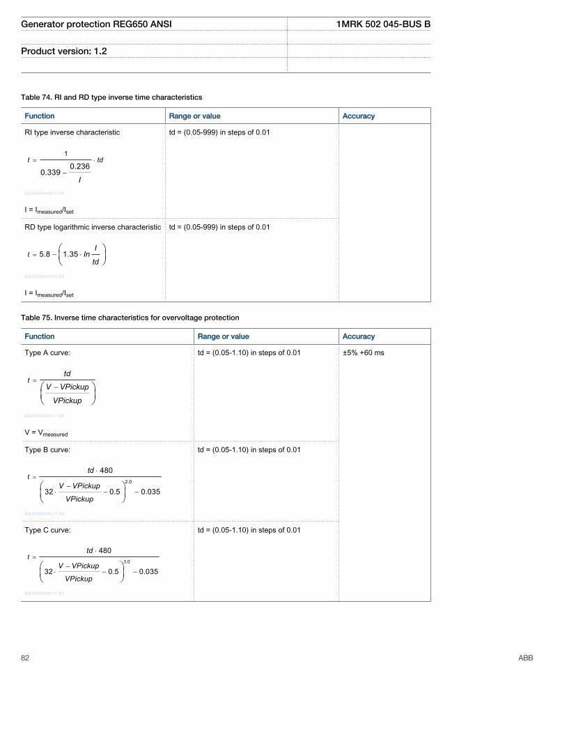
Table 74. RI and RD type inverse time characteristics
Function Range or value Accuracy
RI type inverse characteristic
= ×
-
1
0.2360.339
t td
IEQUATION1656 V1 EN
I = Imeasured/Iset
td = (0.05-999) in steps of 0.01
RD type logarithmic inverse characteristic
= - ×æ öç ÷è ø
5.8 1.35tI
Intd
EQUATION1657 V1 EN
I = Imeasured/Iset
td = (0.05-999) in steps of 0.01
Table 75. Inverse time characteristics for overvoltage protection
Function Range or value Accuracy
Type A curve:
=-æ ö
ç ÷è ø
ttd
V VPickup
VPickup
EQUATION1661 V1 EN
V = Vmeasured
td = (0.05-1.10) in steps of 0.01 ±5% +60 ms
Type B curve:
=×
-× - -
æ öç ÷è ø
2.0
480
32 0.5 0.035
ttd
V VPickup
VPickup
EQUATION1662 V1 EN
td = (0.05-1.10) in steps of 0.01
Type C curve:
=×
-× - -
æ öç ÷è ø
3.0
480
32 0.5 0.035
ttd
V VPickup
VPickup
EQUATION1663 V1 EN
td = (0.05-1.10) in steps of 0.01
Generator protection REG650 ANSI 1MRK 502 045-BUS B
Product version: 1.2
82 ABB

Table 76. Inverse time characteristics for undervoltage protection
Function Range or value Accuracy
Type A curve:
=-æ ö
ç ÷è ø
tdt
VPickup V
VPickup
EQUATION1658 V1 EN
V = Vmeasured
td = (0.05-1.10) in steps of 0.01 ±5% +60 ms
Type B curve:
×= +
-× -
æ öç ÷è ø
2.0
4800.055
32 0.5
tdt
VPickup V
VPickup
EQUATION1659 V1 EN
V = Vmeasured
td = (0.05-1.10) in steps of 0.01
Table 77. Inverse time characteristics for residual overvoltage protection
Function Range or value Accuracy
Type A curve:
=-æ ö
ç ÷è ø
ttd
V VPickup
VPickup
EQUATION1661 V1 EN
V = Vmeasured
td = (0.05-1.10) in stepsof 0.01
±5% +70 ms
Type B curve:
=×
-× - -
æ öç ÷è ø
2.0
480
32 0.5 0.035
ttd
V VPickup
VPickup
EQUATION1662 V1 EN
td = (0.05-1.10) in stepsof 0.01
Type C curve:
=×
-× - -
æ öç ÷è ø
3.0
480
32 0.5 0.035
ttd
V VPickup
VPickup
EQUATION1663 V1 EN
td = (0.05-1.10) in stepsof 0.01
Generator protection REG650 ANSI 1MRK 502 045-BUS B
Product version: 1.2
ABB 83

21. Ordering for Customized IED
Guidelines
Carefully read and follow the set of rules to ensure problem-free order management. Be aware that certain functions canonly be ordered in combination with other functions and that some functions require specific hardware selections.
Product specification
Basic IED 650 platform and common functions housed in 3U 1/1 sized 19” casing
REG650 Quantity: 1MRK 006 526-AC
Option:
Customer specific configuration On request
Connection type for Analog modules
Rule: One connection type must be selected
Compression terminals 1MRK 002 960-CA
Ring lug terminals 1MRK 002 960-DA
Connection type for Power supply, Input/Output and communication modules
Rule: One connection type must be selected
Compression terminals 1MRK 002 960-EA
Ring lug terminals 1MRK 002 960-FA
Power supply module
Rule: One Power supply module must be specified
Power supply module(PSM) 48-125 VDC 1KHL178073R0001
110-250 VDC, 100–240V AC 1KHL178082R0001
Differential protection
Rule: One and only one of Transformer differential protection or Generator differential protection must be ordered
Transformer differential protection, three winding (T3WPDIF, 87T) Qty: 1MRK 004 904-BB
Generator differential protection (GENPDIF, 87G) Qty: 1MRK 004 904-EA
Generator protection REG650 ANSI 1MRK 502 045-BUS B
Product version: 1.2
84 ABB
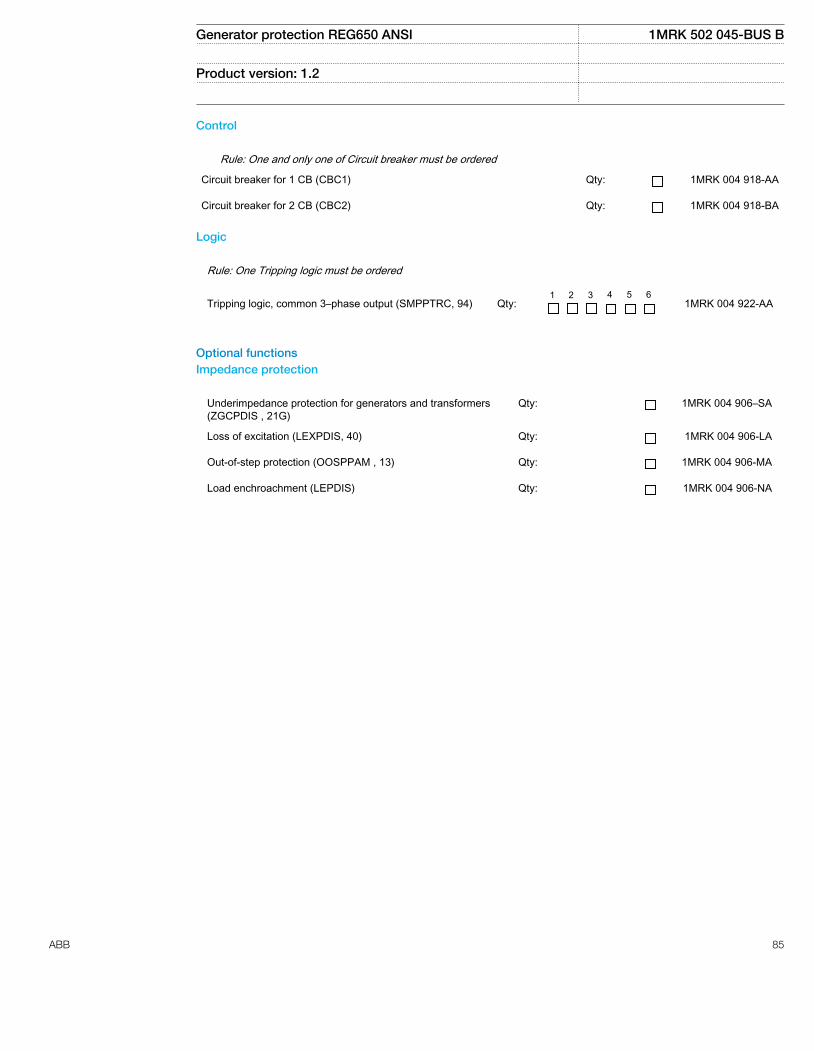
Control
Rule: One and only one of Circuit breaker must be ordered
Circuit breaker for 1 CB (CBC1) Qty: 1MRK 004 918-AA
Circuit breaker for 2 CB (CBC2) Qty: 1MRK 004 918-BA
Logic
Rule: One Tripping logic must be ordered
Tripping logic, common 3–phase output (SMPPTRC, 94)
Qty:
1 2 3 4 5 6 1MRK 004 922-AA
Optional functionsImpedance protection
Underimpedance protection for generators and transformers(ZGCPDIS , 21G)
Qty: 1MRK 004 906–SA
Loss of excitation (LEXPDIS, 40) Qty: 1MRK 004 906-LA
Out-of-step protection (OOSPPAM , 13) Qty: 1MRK 004 906-MA
Load enchroachment (LEPDIS) Qty: 1MRK 004 906-NA
Generator protection REG650 ANSI 1MRK 502 045-BUS B
Product version: 1.2
ABB 85
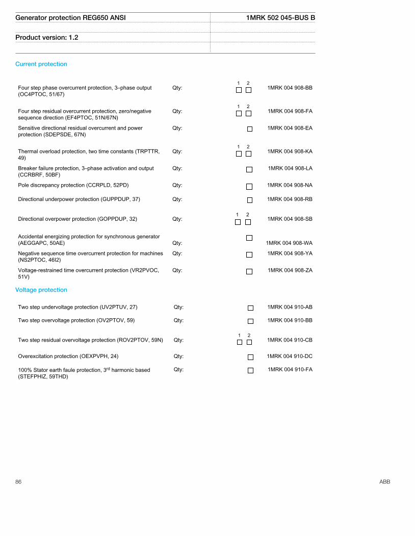
Current protection
Four step phase overcurrent protection, 3–phase output(OC4PTOC, 51/67)
Qty:
1 2 1MRK 004 908-BB
Four step residual overcurrent protection, zero/negativesequence direction (EF4PTOC, 51N/67N)
Qty:
1 2 1MRK 004 908-FA
Sensitive directional residual overcurrent and powerprotection (SDEPSDE, 67N)
Qty: 1MRK 004 908-EA
Thermal overload protection, two time constants (TRPTTR,49)
Qty:
1 2 1MRK 004 908-KA
Breaker failure protection, 3–phase activation and output(CCRBRF, 50BF)
Qty: 1MRK 004 908-LA
Pole discrepancy protection (CCRPLD, 52PD) Qty: 1MRK 004 908-NA
Directional underpower protection (GUPPDUP, 37) Qty: 1MRK 004 908-RB
Directional overpower protection (GOPPDUP, 32)
Qty:
1 2 1MRK 004 908-SB
Accidental energizing protection for synchronous generator(AEGGAPC, 50AE)
Qty:
1MRK 004 908-WA
Negative sequence time overcurrent protection for machines(NS2PTOC, 46I2)
Qty: 1MRK 004 908-YA
Voltage-restrained time overcurrent protection (VR2PVOC,51V)
Qty: 1MRK 004 908-ZA
Voltage protection
Two step undervoltage protection (UV2PTUV, 27) Qty: 1MRK 004 910-AB
Two step overvoltage protection (OV2PTOV, 59) Qty: 1MRK 004 910-BB
Two step residual overvoltage protection (ROV2PTOV, 59N)
Qty:
1 2 1MRK 004 910-CB
Overexcitation protection (OEXPVPH, 24) Qty: 1MRK 004 910-DC
100% Stator earth faule protection, 3rd harmonic based(STEFPHIZ, 59THD)
Qty: 1MRK 004 910-FA
Generator protection REG650 ANSI 1MRK 502 045-BUS B
Product version: 1.2
86 ABB
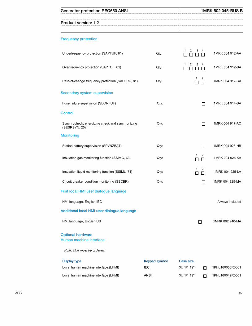
Frequency protection
Underfrequency protection (SAPTUF, 81)
Qty:
1 2 3 4 1MRK 004 912-AA
Overfrequency protection (SAPTOF, 81)
Qty:
1 2 3 4 1MRK 004 912-BA
Rate-of-change frequency protection (SAPFRC, 81)
Qty:
1 2 1MRK 004 912-CA
Secondary system supervision
Fuse failure supervision (SDDRFUF) Qty: 1MRK 004 914-BA
Control
Synchrocheck, energizing check and synchronizing(SESRSYN, 25)
Qty: 1MRK 004 917-AC
Monitoring
Station battery supervision (SPVNZBAT) Qty: 1MRK 004 925-HB
Insulation gas monitoring function (SSIMG, 63)
Qty:
1 2 1MRK 004 925-KA
Insulation liquid monitoring function (SSIML, 71)
Qty:
1 2 1MRK 004 925-LA
Circuit breaker condition monitoring (SSCBR) Qty: 1MRK 004 925-MA
First local HMI user dialogue language
HMI language, English IEC Always included
Additional local HMI user dialogue language
HMI language, English US 1MRK 002 940-MA
Optional hardwareHuman machine interface
Rule: One must be ordered.
Display type Keypad symbol Case size
Local human machine interface (LHMI) IEC 3U 1/1 19" 1KHL160055R0001
Local human machine interface (LHMI) ANSI 3U 1/1 19" 1KHL160042R0001
Generator protection REG650 ANSI 1MRK 502 045-BUS B
Product version: 1.2
ABB 87
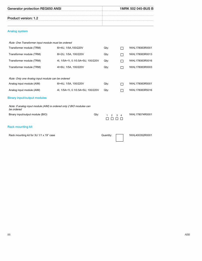
Analog system
Rule: One Transformer input module must be ordered
Transformer module (TRM) 6I+4U, 1/5A,100/220V Qty: 1KHL178083R0001
Transformer module (TRM) 8I+2U, 1/5A, 100/220V Qty: 1KHL178083R0013
Transformer module (TRM) 4I, 1/5A+1I, 0.1/0.5A+5U, 100/220V Qty: 1KHL178083R0016
Transformer module (TRM) 4I+6U, 1/5A, 100/220V Qty: 1KHL178083R0003
Rule: Only one Analog input module can be ordered
Analog input module (AIM) 6I+4U, 1/5A, 100/220V Qty: 1KHL178083R5001
Analog input module (AIM) 4I, 1/5A+1I, 0.1/0.5A+5U, 100/220V Qty: 1KHL178083R5016
Binary input/output modules
Note: If analog input module (AIM) is ordered only 2 BIO modules canbe ordered
Binary input/output module (BIO) Qty: 1 2 3 4 1KHL178074R0001
Rack mounting kit
Rack mounting kit for 3U 1/1 x 19” case Quantity: 1KHL400352R0001
Generator protection REG650 ANSI 1MRK 502 045-BUS B
Product version: 1.2
88 ABB
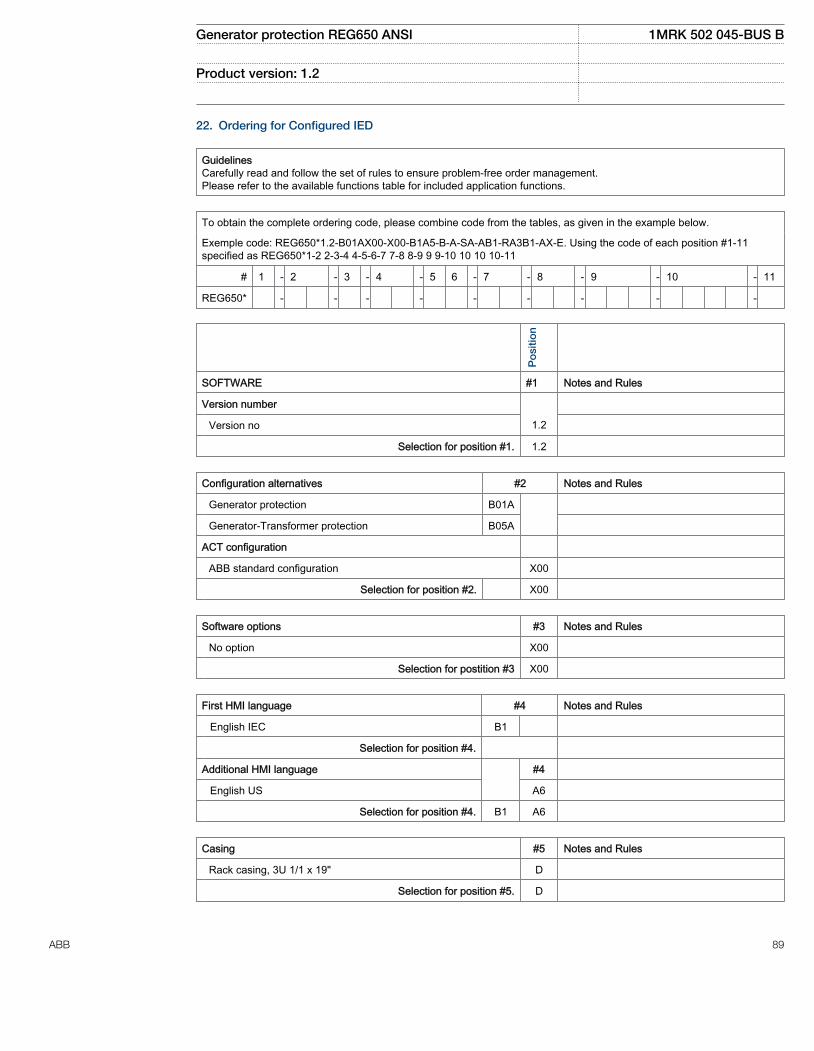
22. Ordering for Configured IED
GuidelinesCarefully read and follow the set of rules to ensure problem-free order management.Please refer to the available functions table for included application functions.
To obtain the complete ordering code, please combine code from the tables, as given in the example below.
Exemple code: REG650*1.2-B01AX00-X00-B1A5-B-A-SA-AB1-RA3B1-AX-E. Using the code of each position #1-11specified as REG650*1-2 2-3-4 4-5-6-7 7-8 8-9 9 9-10 10 10 10-11
# 1 - 2 - 3 - 4 - 5 6 - 7 - 8 - 9 - 10 - 11
REG650* - - - - - - - - -
Po
sitio
n
SOFTWARE #1 Notes and Rules
Version number
Version no 1.2
Selection for position #1. 1.2
Configuration alternatives #2 Notes and Rules
Generator protection B01A
Generator-Transformer protection B05A
ACT configuration
ABB standard configuration X00
Selection for position #2. X00
Software options #3 Notes and Rules
No option X00
Selection for postition #3 X00
First HMI language #4 Notes and Rules
English IEC B1
Selection for position #4.
Additional HMI language #4
English US A6
Selection for position #4. B1 A6
Casing #5 Notes and Rules
Rack casing, 3U 1/1 x 19" D
Selection for position #5. D
Generator protection REG650 ANSI 1MRK 502 045-BUS B
Product version: 1.2
ABB 89

Mounting details with IP40 of protection from the front #6 Notes and Rules
No mounting kit included X
Rack mounting kit for 3U 1/1 x 19" H
Selection for position #6.
Connection type for Power supply, Input/output andCommunication modules
#7 Notes and Rules
Compression terminals S
Ringlug terminals R
Power supply
Slot position:
pPSM
100-240V AC, 110-250V DC, 9BO A
48-125V DC, 9BO B
Selection for position #7.
Human machine interface #8 Notes and Rules
Local human machine interface, OL7000, ANSI3U 1/1 x 19", Basic
D
Detached LHMI
No detached mounting of LHMI X0
Selection for position #8. D X0
Connection type for Analog modules #9 Notes and Rules
Compression terminals S
Ringlug terminals R
Analog system
Slot position: p2
Transformer module, 4I, 1/5A+1I, 0.1/0.5A+5U,100/220V
A3
Slot position: p4
Analog input module, 6I + 4U, 1/5A, 100/220V B1
Selection for position #9. A3 B1
Generator protection REG650 ANSI 1MRK 502 045-BUS B
Product version: 1.2
90 ABB

Binary input/output module #10 Notes and Rules
Slot position (rear view) p5 p6
Available slots in 1/1 case
No board in slot X X AIM in p4
Binary input/output module 9 BI, 3 NO Trip, 5 NO Signal, 1CO Signal
A A p5 basic, p6 optional
Selection for position #10. A
Communication and processing module #11 Notes and Rules
Slot position (rear view)
pCO
M
12BI, IRIG-B, RS485, Ethernet, LC optical, ST serial F
Selection for position #11. F
Generator protection REG650 ANSI 1MRK 502 045-BUS B
Product version: 1.2
ABB 91

23. Ordering for Accessories
External resistor unit
High impedance resistor unit 1-ph with resistor and voltagedependent resistor for 20-100V operating voltage
Quantity: RK795101-MA
High impedance resistor unit 1-ph with resistor and voltagedependent resistor for 100-400V operating voltage
Quantity: RK795101-CB
Configuration and monitoring tools
Front connection cable between LCD-HMI and PC Quantity: 1MRK 001 665-CA
LED Label special paper A4, 1 pc Quantity: 1MRK 002 038-CA
LED Label special paper Letter, 1 pc Quantity: 1MRK 002 038-DA
External interface units for Rotor earth fault protection
Injection unit for Rotor earth fault protection (RXTTE 4) Quantity: 1MRK 002 108-BA
Protective resistor on plate Quantity: RK795102-AD
Manuals
Note: One (1) IED Connect DVD containing user documentationOperation manualTechnical manualInstallation manualCommissioning manualApplication manualCommunication protocol manual, DNP3Communication protocol manual, IEC61850-8-1Communication protocol manual, IEC60870-5-103Cyber security deployment guidelinesType test certificateEngineering manualPoint list manual, DNP3Connectivity packages and LED label template is always included for each IED
Rule: Specify additional quantity of IED Connect DVD requested
User documentation Quantity: 1MRK 003 500-AA
Generator protection REG650 ANSI 1MRK 502 045-BUS B
Product version: 1.2
92 ABB
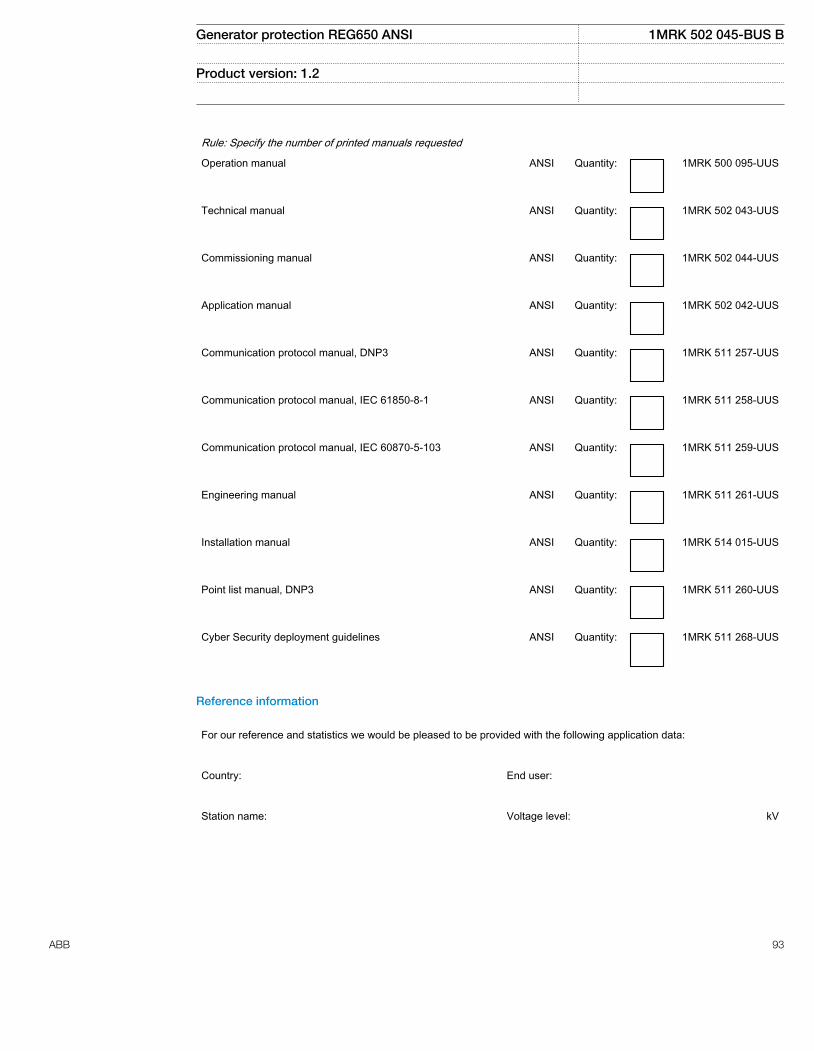
Rule: Specify the number of printed manuals requested
Operation manual ANSI Quantity: 1MRK 500 095-UUS
Technical manual ANSI Quantity: 1MRK 502 043-UUS
Commissioning manual ANSI Quantity: 1MRK 502 044-UUS
Application manual ANSI Quantity: 1MRK 502 042-UUS
Communication protocol manual, DNP3 ANSI Quantity: 1MRK 511 257-UUS
Communication protocol manual, IEC 61850-8-1 ANSI Quantity: 1MRK 511 258-UUS
Communication protocol manual, IEC 60870-5-103 ANSI Quantity: 1MRK 511 259-UUS
Engineering manual ANSI Quantity: 1MRK 511 261-UUS
Installation manual ANSI Quantity: 1MRK 514 015-UUS
Point list manual, DNP3 ANSI Quantity: 1MRK 511 260-UUS
Cyber Security deployment guidelines ANSI Quantity: 1MRK 511 268-UUS
Reference information
For our reference and statistics we would be pleased to be provided with the following application data:
Country: End user:
Station name: Voltage level: kV
Generator protection REG650 ANSI 1MRK 502 045-BUS B
Product version: 1.2
ABB 93

Related documents
Documents related to REG650 Identity number
Application manual 1MRK 502 042-UUS
Technical manual 1MRK 502 043-UUS
Commissioning manual 1MRK 502 044-UUS
Product Guide 1MRK 502 045-BUS
Type test certificate 1MRK 502 045-TUS
Rotor Ground Fault Protection with Injection Unit RXTTE4 and REG670 1MRG001910
Application notes for Circuit Breaker Control 1MRG006806
650 series manuals Identity number
Communication protocol manual, DNP3 1MRK 511 257-UUS
Communication protocol manual, IEC 61850–8–1 1MRK 511 258-UUS
Communication protocol manual, IEC 60870-5-103 1MRK 511 259-UUS
Cyber Security deployment guidelines 1MRK 511 268-UUS
Point list manual, DNP3 1MRK 511 260-UUS
Engineering manual 1MRK 511 261-UUS
Operation manual 1MRK 500 095-UUS
Installation manual 1MRK 514 015-UUS
Generator protection REG650 ANSI 1MRK 502 045-BUS B
Product version: 1.2
94 ABB

95

Contact us
ABB Inc.1021 Main Campus DriveRaleigh, NC 27606, USAPhone Toll Free: 1-800-HELP-365,menu option #8
ABB Inc.3450 Harvester RoadBurlington, ON L7N 3W5, CanadaPhone Toll Free: 1-800-HELP-365,menu option #8
ABB Mexico S.A. de C.V.Paseo de las Americas No. 31 LomasVerdes 3a secc.53125, Naucalpan, Estado De Mexico,MEXICOPhone (+1) 440-585-7804, menuoption #8
1MR
K 5
02 0
45-B
US
B©
Cop
yrig
ht 2
012
AB
B. A
ll rig
hts
rese
rved
.
![INDEX [] and Machinery... · ansi standard 1792–1816 ... ansi b4.2 642, 644, 646, 648–655, 657. index 2559 ansi b4.4m 656 ansi b47.1 1882 ansi b5.18 920, 922–924 ansi b6. 7](https://static.fdocuments.us/doc/165x107/5aa7faa47f8b9aee748cbd3f/index-and-machineryansi-standard-17921816-ansi-b42-642-644-646.jpg)