Generator Maintenance Testing 6 Slides Per Page
12
9/26/2008 1 Day 5: Maintenance Philosophy & Day 5: Maintenance Philosophy & Generator Maintenance Testing Generator Maintenance Testing ELEC 7050: Generator Technology ELEC 7050: Generator Technology Design and Applications Design and Applications Dr. Ramesh Bansal School of Information T echnology and Electrical Engineering, Axon Bldg, 47/212 University of Queensland, St Lucia, 4072 [email protected] Ph: 33653394 1 Maintenance philosophies Maintenance philosophies Generally , maintenance philosophies can be categorized into breakdown maintenance planned maintenance predictive maintenance condition-based maintenance (CBM) Breakdown maintenance Breakdown maintenance This type of approach (fix it as required) is usually employed for short term economic gains with little regard to the future of the specific piece of equipment. Rarely used in generator maintenance but commonly applied to smaller components where repair is more costly than replacement and where loss of particular component during operation does not disrupt the generation of electric power Planned maintenance Planned maintenance Predominant in maintaining critical equipment in power plants. Based on experience acquired during many years of operation, on the reliability of the equipment, as well as on load demands, weather, personnel availability, coordination with other plants of the same utility. Predictive maintenance Predictive maintenance In predictive maintenance the schedule is based mainly on statistical calculations. Calculations take into account parameters such as mean time to failure (MTTF) of critical components, e.g. age of the insulation components, and type of insulation (insulation systems), load cycles, and abnormal operation events. It is important to recognize that predictive maintenance, together with planned maintenance, cannot determine in most cases the optimal time to inspect, maintain, and refurbish a specific piece of equipment, in particular something as complex as a large turbogenerator. Planned and/or predictive maintenance has proved to b e adequate over many years of operation Condition based maintenance (CBM) Condition based maintenance (CBM) Most recent approach to guide station personnel in determining when to inspect, maintai n, and refurbish a generator and other plant equipment. As the name indicates, CBM operations follow a concrete need by a component or apparatus to be refurbished. CBM can only be applied when equipment is monitored by a number of on-line, real-time sensors, as well as off- line periodic testing routines. Although requiring an initial higher capital investment in instrumentation, CBM is perceived as providing, in the long run, a more reliable and less expensive operation.
-
Upload
ashwani2101 -
Category
Documents
-
view
219 -
download
0
Transcript of Generator Maintenance Testing 6 Slides Per Page

8/6/2019 Generator Maintenance Testing 6 Slides Per Page
http://slidepdf.com/reader/full/generator-maintenance-testing-6-slides-per-page 1/11
9/26/2008
1
Day 5: Maintenance Philosophy &Day 5: Maintenance Philosophy &Generator Maintenance TestingGenerator Maintenance Testing
ELEC 7050: Generator TechnologyELEC 7050: Generator TechnologyDesign and ApplicationsDesign and Applications
Dr. Ramesh BansalSchool of Information Technology and Electrical
Engineering, Axon Bldg, 47/212University of Queensland, St Lucia, 4072
[email protected]: 33653394
1
Maintenance philosophiesMaintenance philosophies
Generally, maintenance philosophies can becategorized intobreakdown maintenanceplanned maintenancepredictive maintenancecondition-based maintenance (CBM)
Breakdown maintenanceBreakdown maintenanceThis type of approach (fix it as required) isusually employed for short term economic gainswith little regard to the future of the specificpiece of equipment.Rarely used in generator maintenance butcommonly applied to smaller components
where repair is more costly than replacementand where loss of particular component duringoperation does not disrupt the generation of electric power
Planned maintenancePlanned maintenance
Predominant in maintaining criticalequipment in power plants.Based on experience acquired duringmany years of operation, on the reliabilityof the equipment, as well as on load
demands, weather, personnel availability,coordination with other plants of thesame utility.
Predictive maintenancePredictive maintenanceIn predictive maintenance the schedule is based mainly onstatistical calculations.Calculations take into account parameters such as meantime to failure (MTTF) of critical components, e.g. age of the insulation components, and type of insulation(insulation systems), load cycles, and abnormal operationevents.It is important to recognize that predictive maintenance,together with planned maintenance, cannot determine inmost cases the optimal time to inspect, maintain, andrefurbish a specific piece of equipment, in particularsomething as complex as a large turbogenerator.Planned and/or predictive maintenance has proved to beadequate over many years of operation
Condition based maintenance (CBM)Condition based maintenance (CBM)Most recent approach to guide station personnel indetermining when to inspect, maintain, and refurbish agenerator and other plant equipment.As the name indicates, CBM operations follow a concreteneed by a component or apparatus to be refurbished.CBM can only be applied when equipment is monitoredby a number of on-line, real-time sensors, as well as off-line periodic testing routines.Although requiring an initial higher capital investment ininstrumentation, CBM is perceived as providing, in thelong run, a more reliable and less expensive operation.
8/6/2019 Generator Maintenance Testing 6 Slides Per Page
http://slidepdf.com/reader/full/generator-maintenance-testing-6-slides-per-page 2/11
9/26/2008
2
Operational & maintenance historyOperational & maintenance history
Parameters that will influence the condition of generator are:
Operating statisticsOperating hoursNumber of starts/stopsStress eventsDescriptive summary of operating problemsOutage and maintenance statisticsIdentified OEM (Original EquipmentManufacturer) generic equipment problems
Maintenance frequencyMaintenance frequencyImportant elements that determine
maintenance intervals are :OEM recommendationspreventive philosophybreakdown philosophyextending inspection intervalsnumber of years of operationoperating hourssystem schedulescondition based maintenance
Type of maintenance:Type of maintenance: extentextentof maintenanceof maintenance
In different conditions the same scopecan take vastly different lengths of time tobe completed.
Thus more than the duration of theoutage, the scope of disassembly of thegenerator is the true indicator of theextent of the work
Type of Type of maintenance: repair or maintenance: repair or replacementreplacement
RepairsWhen components are capable of being fixed in a timelyfashionMore economical than replacementWhen reliability of operation is not compromised to anysignificant extent
Replacement When components are not capable of being fixedWhen replacement is more cost effectiveWhen reliability of operation could be compromised by arepair one critical component
Rehabilitation and upgrading/Rehabilitation and upgrading/
upratingupratingUprating a generator to any significant degree alwaysrequires performing calculations to extrapolateoperation out to the higher load, based on heat runtesting of the machine at its present maximum load.Upgrading is indicated by a need or desire to increase
the availability or reliability of the unit by usingcomponents designed and manufactured to newerstandards.Rehabilitation is normally understood the
refurbishment of the machine, basically withcomponents and techniques identical or similar to theoriginals, with the purpose of bringing the generatorback to its previous condition.
Specialist ContractorsSpecialist ContractorsCompetitor (to OEM) repair facilityFunction-specific contractor (e.g. one that specializes inretaining ring removal)Usually have high-level knowledge about the equipmentSpecialized people (experts)Specialized toolsGenerally a lower cost optionGenerally more limited resources than the OEMCannot always cope with the unforeseenStation must be selective about what work is let out tothird-party contractorsBased on past performance and knowledge of their capabilityMay be in conflict with OEM long-term warranties, if andwhen they still apply
8/6/2019 Generator Maintenance Testing 6 Slides Per Page
http://slidepdf.com/reader/full/generator-maintenance-testing-6-slides-per-page 3/11
9/26/2008
3
Spare parts: Minor SparesSpare parts: Minor SparesParts that are needed for regular maintenanceGeneral consumable materials (e.g., gaskets, “O” rings,bolts, and stator re-wedge material)Parts with high failure or wear rates (e.g., slip-ringbrushes, ground brushes , and brush holders)Parts identified as having the potential to create outageextensions if not available (e.g., insulation tapes, bell-shaped (spring) washers, and PTE hoses)Surge capacitors (for those units where used)Thermocouples and RTDs (resistance temperaturedetectors)Usually these minor spares are of low cos t
Spare parts: Major SparesSpare parts: Major SparesSpare rotorSpare statorSpare stator bars (should include at least two bottom bars and anumber equal to those required to lift in the event a bottom barmust be replaced)Standoff insulatorsTerminal bushingsCurrent transformers (CTs)Bearings and/or bearing componentsH2 seals and/or seal componentsCollector rings and collector-ring sleeve insulationNormally these will be of medium to high carrying cost
AuxiliariesExcitation components (diodes, rectifiers, etc.)Enough spare parts for every single auxiliar y.
Work site location Work site location
On SiteMinor and major outage work Both (major & minor outage) generally done on
site if possible
Off SiteTransport equipment to external facilityUsually for major work such as rotor rewindsUsually means the job cannot be done on siteOr is more cost effective to do at off site
Workforce WorkforceIn-house
Station staff Other internal resources
OEMMajor manufacturerAdvantage of having specific knowledge about theequipmentSpecialized people not available within the operator’s own
organizationSpecialized toolsGenerally more expensive than in-house resourcesLess risk than using internal and/or non-OEM personnelUsually the highest work quality
Generator maintenance testingGenerator maintenance testingIt generally refers to tests that are done generally off line orat some special condition, as opposed to on-line testingwhich is actually a form of monitoring for diagnosticpurposes while the generator is producing power.However, there are certain on-line tests that are done andclassified as tests rather than monitoring.Tests on large turbogenerators are a very serious business.Improper testing or test preparation can be expensive andcan cause unnecessary losses to the machine and expose thepersonnel to lethal dangers.Hence tests must be carried out only by well-trainedprofessionals, following all relevant and applicable rules andstandards.To achieve the maximum efficiency and reliability, generatorshave to be tested and maintained regularly.
Various aspects of generatorVarious aspects of generatormaintenance testingmaintenance testing
Stator core electrical & mechanical (E &M) testsStator winding E &M testsWater-cooled stator winding testsRotor E &M testingHydrogen seals [Nondestructive examination(NDE) and insulation resistance (IR)]Bearings (NDE and IR)Thermal sensitivity test and analysisHeat run testingHydrogen leak detection
8/6/2019 Generator Maintenance Testing 6 Slides Per Page
http://slidepdf.com/reader/full/generator-maintenance-testing-6-slides-per-page 4/11
9/26/2008
4
StatorStator core testscore testsMechanical tests core tightness core and frame vibration tests
Electrical tests EL CID (Electromagnetic Core Imperfection
Detector) testing Rated flux test with infrared scan Core loss test Through-bolt insulation resistance Insulation Resistance (IR) of flux screens
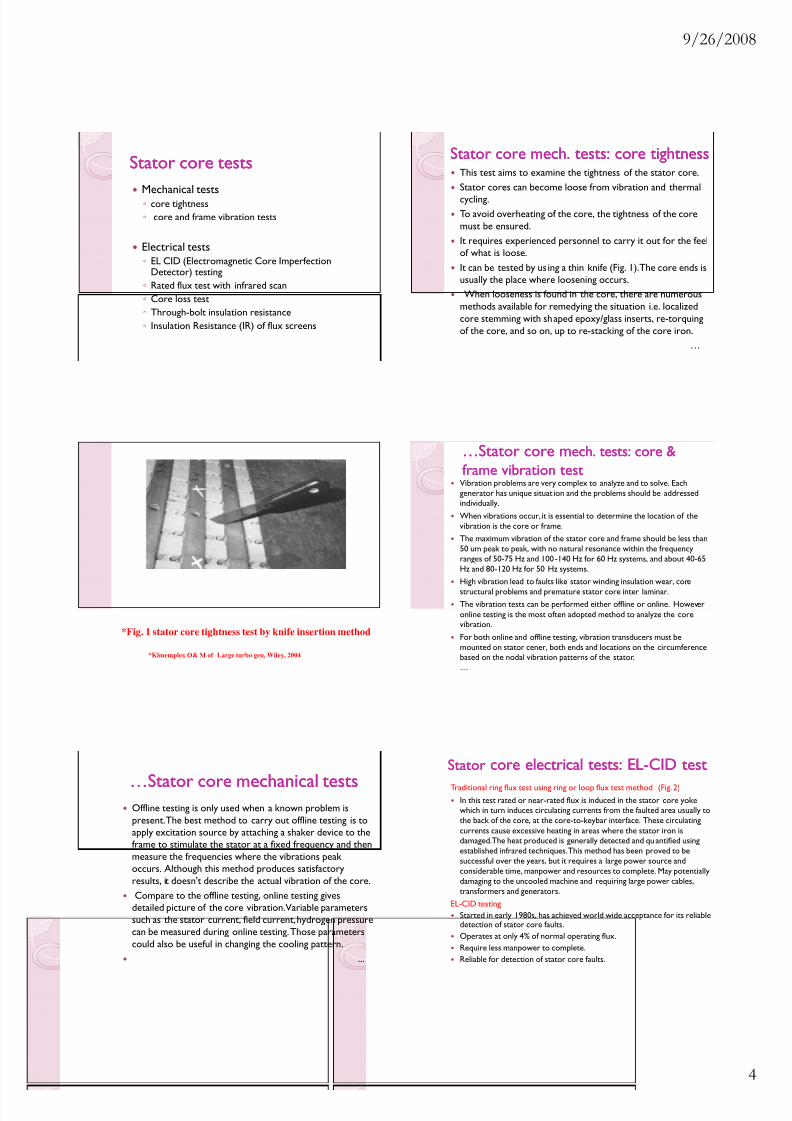
Stator core mStator core m ech. tests: core tightnessech. tests: core tightnessThis test aims to examine the tightness of the stator core.Stator cores can become loose from vibration and thermalcycling.To avoid overheating of the core, the tightness of the coremust be ensured.It requires experienced personnel to carry it out for the feelof what is loose.It can be tested by us ing a thin knife (Fig. 1). The core ends isusually the place where loosening occurs.When looseness is found in the core, there are numerous
methods available for remedying the situation i.e. localizedcore stemming with shaped epoxy/glass inserts, re-torquingof the core, and so on, up to re-stacking of the core iron.
…
*Fig. 1 stator core tightness test by knife insertion method
*Klmempler, O& M of Large turbo gen, Wiley, 2004
…Stator core m…Stator core m ech. tests: core &ech. tests: core &frame vibration testframe vibration test
Vibration problems are very complex to analyze and to solve. Eachgenerator has unique situat ion and the problems should be addressedindividually.When vibrations occur, it is essential to determine the location of thevibration is the core or frame.The maximum vibration of the stator core and frame should be less than50 um peak to peak, with no natural resonance within the frequencyranges of 50-75 Hz and 100 -140 Hz for 60 Hz systems, and about 40-65Hz and 80-120 Hz for 50 Hz systems.High vibration lead to faults like stator winding insulation wear, corestructural problems and premature stator core inter laminar.The vibration tests can be performed either offline or online. Howeveronline testing is the most often adopted method to analyze the corevibration.For both online and offline testing, vibration transducers must bemounted on stator cener, both ends and locations on the circumferencebased on the nodal vibration patterns of the stator.…
…Stator core m…Stator core m echanical testsechanical testsOffline testing is only used when a known problem ispresent. The best method to carry out offline testing is toapply excitation source by attaching a shaker device to theframe to stimulate the stator at a fixed frequency and thenmeasure the frequencies where the vibrations peak occurs. Although this method produces satisfactoryresults, it doesn't describe the actual vibration of the core.Compare to the offline testing, online testing gives
detailed picture of the core vibration. Variable parameterssuch as the stator current, field current, hydrogen pressurecan be measured during online testing. Those parameterscould also be useful in changing the cooling pattern.
...
StatorStator core electrical tests: ELcore electrical tests: EL- -CID testCID testTraditional ring flux test using ring or loop flux test method (Fig. 2)
In this test rated or near-rated flux is induced in the stator core yokewhich in turn induces circulating currents from the faulted area usually tothe back of the core, at the core-to-keybar interface. These circulatingcurrents cause excessive heating in areas where the stator iron isdamaged. The heat produced is generally detected and qu antified usingestablished infrared techniques. This method has been proved to besuccessful over the years, but it requires a large power source andconsiderable time, manpower and resources to complete. May potentiallydamaging to the uncooled machine and requiring large power cables,transformers and generators.
EL-CID testingStarted in early 1980s, has achieved world wide acceptance for its reliabledetection of stator core faults.Operates at only 4% of normal operating flux.Require less manpower to complete.Reliable for detection of stator core faults.
8/6/2019 Generator Maintenance Testing 6 Slides Per Page
http://slidepdf.com/reader/full/generator-maintenance-testing-6-slides-per-page 5/11
9/26/2008
5
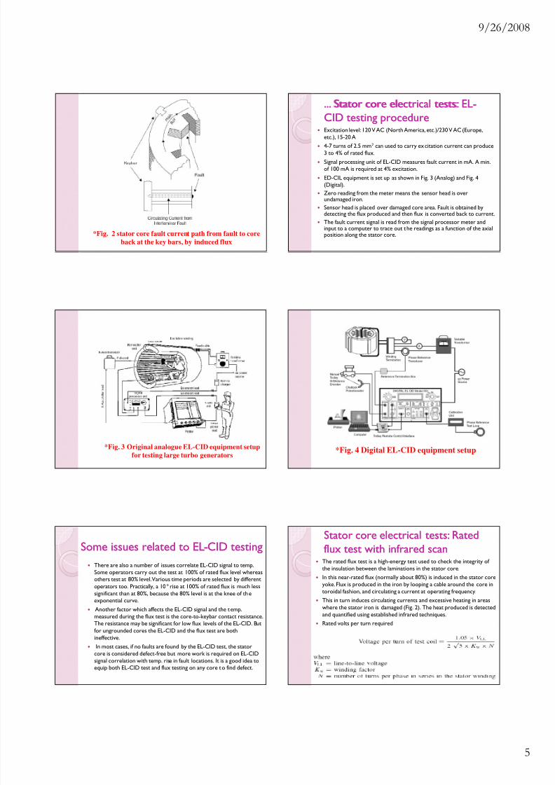
*Fig. 2 stator core fault current path from fault to coreback at the key bars, by induced flux
...... Stator core electrical tests: ELStator core electrical tests: EL- -CID testing procedureCID testing procedureExcitation level: 120 V AC (North America, etc.)/230 V AC (Europe,
etc.), 15-20 A4-7 turns of 2.5 mm 2 can used to carry ex citation current can produce3 to 4% of rated flux.Signal processing unit of EL-CID measures fault current in mA. A min.of 100 mA is required at 4% excitation.ED-CIL equipment is set up as shown in Fig. 3 (Analog) and Fig. 4(Digital).Zero reading from the meter means the sensor head is overundamaged iron.Sensor head is placed over damaged core area. Fault is obtained bydetecting the flux produced and then flux is converted back to current.The fault current signal is read from the signal processor meter andinput to a computer to trace out t he readings as a function of the axialposition along the stator core.
*Fig. 3 Original analogue EL-CID equipment setupfor testing large turbo generators
*Fig. 4 Digital EL-CID equipment setup
Some issues related to ELSome issues related to EL--CID testingCID testingThere are also a number of issues correlate EL-CID signal to temp.Some operators carry out the test at 100% of rated flux level whereasothers test at 80% level. Various time periods are selected by differentoperators too. Practically, a 10 ° rise at 100% of rated flux is much lesssignificant than at 80%, because the 80% level is at the knee of th eexponential curve.Another factor which affects the EL-CID signal and the t emp.measured during the flux test is the core-to-keybar contact resistance.The resistance may be significant for low flux levels of the EL-CID. Butfor ungrounded cores the EL-CID and the flux test are bothineffective.In most cases, if no faults are found by the EL-CID test, the stator
core is considered defect-free but more work is required on EL-CIDsignal correlation with temp. rise in fault locations. It is a good idea toequip both EL-CID test and flux testing on any core t o find defect.
Stator core electrical tests: RatedStator core electrical tests: Rated
flux test with infrared scanflux test with infrared scanThe rated flux test is a high-energy test used to check the integrity of the insulation between the laminations in the stator core.In this near-rated flux (normally about 80%) is induced in the stator coreyoke. Flux is produced in the iron by looping a cable around the core intoroidal fashion, and circulating a current at operating frequency.This in turn induces circulating currents and excessive heating in areaswhere the stator iron is damaged (Fig. 2). The heat produced is detectedand quantified using established infrared techniques.Rated volts per turn required
8/6/2019 Generator Maintenance Testing 6 Slides Per Page
http://slidepdf.com/reader/full/generator-maintenance-testing-6-slides-per-page 6/11
9/26/2008
6
Stator core electrical tests: CoreStator core electrical tests: Coreloss testingloss testingStator core loss is a function of terminal voltage.The core loss for any particular generator is always determined at thefactory by th e manufacturer, and is not a test that is generally done atsite.It is determined by the generator being coupled to, and driven by, acalibrated motor. The friction and windage (mechanical) losses arecalculated and separated out from the electrical losses to provide avalue of core loss for the stator.If there is suspected wear of the inter-laminar insulation in the core, ona large scale, it may be possible that a core loss test could be done tocompare the present value to the “as new” value to determine theextent of deterioration occurring. However, the serious challenge of driving the generator at site with a calibrat ed motor, for all practicalpurposes, limits this test to the OEM’s factory.
Stator core electrical tests: throughStator core electrical tests: through- -boltbolt insulation resistanceinsulation resistanceThere are a few manufacturers that provide through-bolts in
their stators to pull the cores tight. These through-bolts arefull-length bolts inserted axially through the core throughholes in the core iron.The entire through-bolt assembly is insulated by epoxy/glasstape wrap or a phenolic tube through the core, and anarrangement of insulators at the pressure plates and nuts.This is done to ensure that the through-bolts do not createany short circuits across the stator core laminations andcause a core failure by circulating currents.To ensure that the insulation is in good condition, theinsulation resistance of the through-bolts is checked bymeggering at 500 V dc. A good reading should be in thehundreds of M Ω range.
Stator core electrical tests: InsulationStator core electrical tests: Insulationresistance of flux screensresistance of flux screens
Most large generators are provided with some form of flux screening for the stator core-end.This is to prevent overheating in the core-ends due tostray flux from the stator end-winding.When flux screens are used, they are insulated from thecore end to ensure that no additional circulatingcurrents flow between the core and the flux screens,
which would create additional unwanted heating in thecore-end.To ensure that the insulation is in good condition, theinsulation resistance of the flux screens is checked bymeggering at 500 V dc.A good reading should be in the hundreds of M Ω range.
StatorStator winding testswinding testsMechanical tests: Wedge tightness Stator end-winding vibration
Electrical tests Determine if serious insulation weakness
exists and as well as verify insulation strengthto normal operation
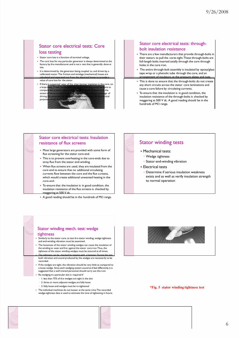
Stator winding mech. test:Stator winding mech. test: wedgewedgetightnesstightnessSimilarly to the stator core, to test th e stator winding, wedge tightnessand end-winding vibration must be examined.The looseness of the stator winding wedges can cause the insulation of the winding to wear and fret against the stator core iron. Thus, thetightness of the stator winding wedges must be ensured at all times.The tightness can be checked by tapping with a hammer. During the test,both vibration and sound produced by the wedges are necessarily to berecorded.If the wedges are tight, the vibration should be very little as compared toa loose wedge. Since each wedging system sound an d feel differently, it issuggested that a well trained personnel should carry out this t est.Re-wedging in a particular slot is required if
1. less than 75% of th e wedges are tight in the slot 2. three or more adjacent wedges are fully loose 3. fully loose end-wedges must be re-tightenedThe individual machines do not loosen at the same t ime. The recordedwedge-tightness data is used to estimate the time of tightening in future.
*Fig. 5 stator winding tightness test
8/6/2019 Generator Maintenance Testing 6 Slides Per Page
http://slidepdf.com/reader/full/generator-maintenance-testing-6-slides-per-page 7/11
9/26/2008
7
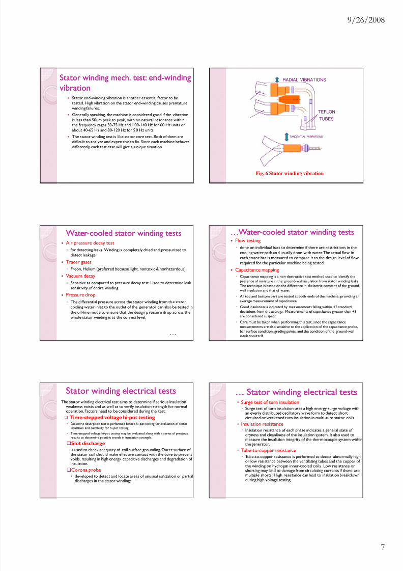
Stator winding mech. test:Stator winding mech. test: endend--windingwindingvibrationvibration
Stator end-winding vibration is another essential factor to betested. High vibration on the stator end-winding causes prematurewinding failures.Generally speaking, the machine is considered good if the vibrationis less than 50um peak to peak, with no natural resonance withinthe frequency rages 50-75 Hz and 1 00-140 Hz for 60 Hz units orabout 40-65 Hz and 80-120 Hz for 5 0 Hz units.The stator winding test is like stator core test. Both of them aredifficult to analyze and expen sive to fix. Since each machine behavesdifferently, each test case will give a unique situation.
RADIAL VIBRATIONS
TEFLON
TUBES
TANGENTIAL VIBRATIONS
Fig. 6 Stator winding vibration
WaterWater- -cooled stator winding testscooled stator winding testsAir pressure decay test
for detecting leaks. Winding is completely dried and pressurized todetect leakage
Tracer gases Freon, Helium (preferred because light, nontoxic & nonhazardous)
Vacuum decay Sensitive as compared to pressure decay test. Used to determine leak
sensitivity of entire winding
Pressure drop The differential pressure across the stator winding from th e stator
cooling water inlet to the outlet of the generator can also be tested inthe off-line mode to ensure that the design p ressure drop across thewhole stator winding is at the correct level.
…
…Water…Water- -cooled stator winding testscooled stator winding testsFlow testing
done on individual bars to determine if there are restrictions in thecooling water path an d usually done with water. The actual flow ineach stator bar is measured to compare it to the design level of flowrequired for the particular machine being tested.
Capacitance mapping Capacitance mapping is a non-destructive test method used to identify the
presence of moisture in the ground-wall insulation from stator winding leaks.The technique is based on the difference in dielectric constant of the ground-wall insulation and that of water.
All top and bottom bars are tested at both ends of the machine, providing anaverage measurement of capacitance.
Good insulation is indicated by measurements falling within ± 2 standarddeviations from the average. Measurements of capacitance greater than +3are considered suspect.
Care must be taken when performing this test, since the capacitancemeasurements are also sensitive to the application of the capacitance probe,bar surface condition, grading paints, and the condition of the ground-wallinsulation itself.
Stator winding electrical testsStator winding electrical testsThe stator winding electrical test aims to determine if serious insulation
weakness exists and as well as to verify insulation strength for normaloperation. Factors need to be considered during the test.
Time-stepped voltage hi-pot testing• Dielectric absorption test is performed before hi-pot testing for evaluation of stator
insulation and suitability for hi-pot testing.• Time-stepped voltage hi-pot testing may be evaluated along with a series of previous
results to determine possible trends in insulation strength.
Slot dischargeis used to check adequacy of coil surface grounding. Outer surface of the stator coil should make effective contact with the core to preventvoids, resulting in high energy capacitive discharges and degradation of insulation.Corona probe• developed to detect and locate areas of unusual ionization or partial
discharges in the stator windings.
… Stator winding electrical tests… Stator winding electrical tests Surge test of turn insulation
Surge test of turn insulation uses a high en ergy surge voltage withan evenly distributed oscillatory wave form to detect shortcircuited or weakened turn insulation in multi-turn stator coils.
Insulation resistanceInsulation resistance of each phase indicates a general state of dryness and cleanliness of the insulation system. It also used tomeasure the insulation integrity of the thermocouple system withinthe generator.
Tube-to-copper resistanceTube-to-copper resistance is performed to detect abnormally highor low resistance between the ventilating tubes and the copper of the winding on hydrogen inner-cooled coils. Low resistance orshorting may lead to damage from circulating currents if there aremultiple shorts. High resistance can lead to insulation breakdownduring high voltage testing.

8/6/2019 Generator Maintenance Testing 6 Slides Per Page
http://slidepdf.com/reader/full/generator-maintenance-testing-6-slides-per-page 8/11
9/26/2008
8
… Stator winding electrical tests… Stator winding electrical testsTube-to-Tube Resistance
is performed to detect abnormally high or low resistancebetween the ventilating tub es on hydrogen inner-cooledcoils. Shorts between the tubes may lead to damage fromcirculating currents. Abnormally high resistance between thetubes may lead to insulation damage between tubes during highvoltage testing.
Phase resistance Measurements should be taken at all maintenance inspections or
repairs so that actual measurements can be compared to factorycalculated values and for phase balance for evaluating potentialproblems.
Rotor mechanical testingRotor mechanical testing Rotor vibration
Vibration measurement is one of the importantmeasurements of the rotor mechanical testing.Vibration is monitored continuously in all turbine andgenerator bearings.Vibration testing is very specialized and requiresadditional equipment to be connected to the vibrationprobes.The type of additional testing inferred would be toallow characterization of the vibration measurementsinto both magnitude and phase relation.
Rotor mechanical testingRotor mechanical testing
Nondestructive examination (NDE) test NDE test of generator rotors is usually done to look for cracks.
There are generally two types of nondestructive examination,surface and volumetric. There are six different test methods:
VisualRadiographicMagnetic particle
Liquid penetrantUltrasonicEddy current
Rotor mechanical testing:Rotor mechanical testing: VisualVisualinspection (VI)inspection (VI)
very good effectiveness if the inspector isknowledgeable and experienced enough.low cost, simple and quick.can be done during any type of generatorwork that is in progress, permitting
correction of faults.However, it is applicable to surfacedefects only and provides no permanentrecord.
Rotor mechanical testing:Rotor mechanical testing:
Radiographic inspection (RT)Radiographic inspection (RT)Usually done by X-ray or gamma units made especially forwelds, castings and forging.The major defects that radiography can detect are interiormacroscopic flaws such as cracks, porosity, and inclusions.Poor welds can be easily seen by this method.Applicable to most materials and once carried out thedefect areas are recorded to provide permanent record.But, it requires skill in getting a good angle of exposure, useof the equipment, and interpreting the indications found.It is also hazardous to the operator’s health.
Rotor mechanical testing:Rotor mechanical testing: MagneticMagnetic
particle inspection (MPI)particle inspection (MPI)MPI is simple to perform and cost effective.Requires high current application to align the magnetic powders thatshow any flaws that are observable.Magnetization is done by passing current through a multi-turned coil,looped through or around the part to be examined, with no electricalcontact.The magnetization field is parallel to the axis of coil-longitudinalmagnetization.MPI is common for use in rotor component inspection of forgings,couplings, and steel wedges.It is excellent for detecting surface or near surface defects.The limitation of MPI is that it is applicable to ferromagnetic materialsonly and does require some sill in interpretation of defect indicationsand recognition of irregular patterns.

8/6/2019 Generator Maintenance Testing 6 Slides Per Page
http://slidepdf.com/reader/full/generator-maintenance-testing-6-slides-per-page 9/11
9/26/2008
9
Rotor mechanical testing:Rotor mechanical testing: LiquidLiquidpenetrantpenetrant inspection (LPI)inspection (LPI)
Liquid-penetrating inspection is widely used forgenerators, specifically on most rotor components,since it can be applied to both ferrous and nonferrousmaterials.It is primarily used for retaining-ring inspection. It isconsidered to have greater sensitivity than magneticparticle inspection, and is also a very cost-effectivemethod.The limitation of LPI is that it only detects surfacedefects and it can only be used in the temp. range of 60-90 F due to viscosity issues with the penetrant.
Rotor mechanical testing:Rotor mechanical testing: UltrasonicUltrasonictest (UT)test (UT)
is the second most widely used NDE method ongenerator components.It is able to detect surface and subsurface defects.It is used for rotor forging bores, retaining rings andspecialized subsurface that can occur in high-st ressareas or the rotor.The disadvantage of this method is that it is difficult toobtain good interpretable signals in areas where thespecimen geometry is complex.It also requires well trained operator to carry out thetesting and translate the results.
*Fig. 7 In-situ robotic rotor retaining-ringultrasonic testing
Rotor mechanical testing:Rotor mechanical testing: Eddy currentEddy currenttest (ECT)test (ECT)Not widely used for generator applications, but it has been useful on occasionwhere tight cracks in retaining rings cannot be seen by LPI, MPI, or UT.Able to penetrate layers of good material to detect hidden flaws in metalssuch as inclusions and tight cracks.The basic principle is that of an alternating current flowing through a coil,producing an alternating magnetic field in the specimen being tested. Whenthe coil is then placed near a test specimen that is conductive, the magneticfield causes eddy currents to flow.This flow of eddy currents depends on the physical and electricalcharacteristics of the test specimen. The eddy currents will avoid cracks and
seek higher conducting regions in the specimen.As the eddy currents flow in the test specimen, they generate their ownmagnetic field. This field interacts with the magnetic field produced by the coiland changes the coil’s impedance.
Specialized instruments then measure and display these changes in theimpedance, allowing the test technician to interpret information about thetest specimen, specifically the presence and size of flaws in it.
Rotor electrical testingRotor electrical testingWinding resistanceInsulation resistancePolarization indexDc hi-potAc hi-potShorted turns detection by
recurrent surge oscillation (RSO) Open circuit test Winding impedence Low voltage dc or Volt drop Low voltage ac or “C” core test Shorted turns detector (flux probe)
Field winding ground detection by By split voltage test By current through forging test
*Fig. 8 Short turns detected by open circuit test
8/6/2019 Generator Maintenance Testing 6 Slides Per Page
http://slidepdf.com/reader/full/generator-maintenance-testing-6-slides-per-page 10/11
9/26/2008
10
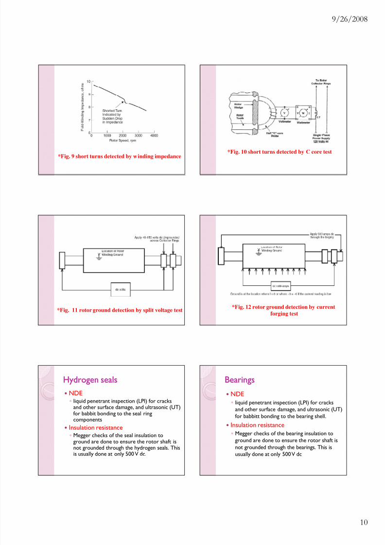
*Fig. 9 short turns detected by winding impedance*Fig. 10 short turns detected by C core test
*Fig. 11 rotor ground detection by split voltage test *Fig. 12 rotor ground detection by currentforging test
Hydrogen sealsHydrogen sealsNDE liquid penetrant inspection (LPI) for cracks
and other surface damage, and ultrasonic (UT)for babbit bonding to the seal ringcomponents
Insulation resistance Megger checks of the seal insulation to
ground are done to ensure the rotor shaft isnot grounded through the hydrogen seals. Thisis usually done at only 500 V dc.
BearingsBearingsNDE liquid penetrant inspection (LPI) for cracks
and other surface damage, and ultrasonic (UT)for babbitt bonding to the bearing shell.
Insulation resistance Megger checks of the bearing insulation to
ground are done to ensure the rotor shaft isnot grounded through the bearings. This isusually done at only 500 V dc
8/6/2019 Generator Maintenance Testing 6 Slides Per Page
http://slidepdf.com/reader/full/generator-maintenance-testing-6-slides-per-page 11/11
9/26/2008
11
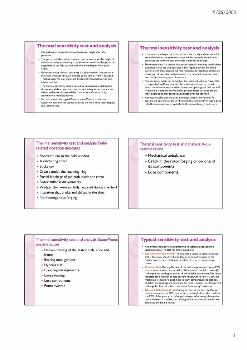
Thermal sensitivity test and analysisThermal sensitivity test and analysisIt is performed when vibrations of unknown origin affect thegenerator.The purpose of the analysis is to narrow the search for the origin of the vibrations by ascertaining if the vibrations are from changes in themagnitude of the field current in the field-winding or from otherorigin.Generator rotor thermal sensitivity is a phenomenon that occurs inthe rotor when its vibration changes as the field cu rrent is changed.This has occurred on generators’ fields of all manufacturers at onetime or another.The thermal sensitivity can b e caused by uneven temp. distributioncircumferentially around the rotor, or by winding forces that are notdistributed uniformly around the rotor’s circumference, or byasymmetrical radial gap forces.Second cause is the large difference in coefficients of thermalexpansion between the copper coils and the steel alloy rotor forgingand components.
Thermal sensitivity test and analysisThermal sensitivity test and analysisIf the rotor winding is not balanced both electrically and mechanicallyaround the rotor, the generator rotor will be unevenly loaded, which
can cause the rotor to bow and cause vibrations to change .From experience it is known that rotor thermal sensitivity rarely affectsoperation when the unit operates in the region between the ratedpower factor lines, because the rotor is below its rated temperature inthis region of operation. Vibrations due to a thermally sensitive rotorare mostly at running speed frequency.The vibrations origin can be further discriminated as bein g “reversibleor repetitive” and “irreversible.” Reversible vibrations are those inwhich the vibration vector, when plotted on a polar graph, will not shift.Irreversible vibrations show a shiftin g vector. These last ones are themost onerous, as they cannot be balanced over the long run.Almost invariable they result in a winding removal and rewind. Tocapture the presence of these vibrations, the constant MW test is donein both directions, namely with the field current ch anged both ways.
Shorted turns in the field windingA ratcheting effectSticky coilCrease under the retaining-ringPartial blockage of gas path inside the rotorRotor stiffness dissymmetryWedges that were partially replaced during overhaulInsulation that broke and shifted in the slotsNonhomogenous forging
Thermal sensitivity test and analysis:Thermal sensitivity test and analysis:FieldField--related vibration indicatesrelated vibration indicates
Mechanical unbalanceCrack in the rotor forging or on one of its componentsLose components
Thermal sensitivity test and analysis:Thermal sensitivity test and analysis: RotorRotorpossible causespossible causes
Uneven heating of the stator coils, core andframeBearing misalignmentH2 seals rubCoupling misalignmentsLoose footingLose componentsFrame twisted
Thermal sensitivity test and analysis:Thermal sensitivity test and analysis: Stator/frameStator/frame
possible causespossible causes
Typical sensitivity test and analysisTypical sensitivity test and analysisA thermal sensitivity test is performed to segregate between thevarious sources. The test has three main parts:Constant MW and MVAR: The aim of this test is to capture a rotorthat is thermally sensitive due to forging asymmetries (due to theforging process or to machining, welding, etc.), or to stator-frameissues.Constant MW: During this part of the test, the generator’s gross MWoutput must remain constant. With MW constant, the field current( If )is changed and readings are taken of the variable parameters. The test isrepeated for a number of field-current values. After a new If is set, themachine is let run for a given time to allow temperatures to stabilize,and then the readings are noted and the time is noted. The field currentis changed in both directions, to capture “ratcheting” problems.Constant Field Current (If): During this part of the t est, the If mustremain constant—the AVR must be set to manual. Under this conditionthe MW of the generator is changed in steps. After every change theunit is allowed to stabilize, and readings of the variables of interest aretaken and the time is noted.