Generation, Visualization, and Editing of 3D...
12
Generation, Visualization, and Editing of 3D Video Takashi Matsuyama and Takeshi Takai Graduate School of Informatics, Kyoto University Yoshidahonmachi, Sakyo-ku, Kyoto, 606-8501, Japan [email protected], [email protected] Abstract 3D video is the ultimate image medium recording dynamic visual events in the real world as is. Recorded object behaviors can be observed from any viewpoint, because 3D video records the object’s full 3D shape, motion, and precise surface properties (i.e. color and texture). In our last paper[1], we presented a method of reconstructing dynamic 3D object shape from multi-view video images, by which a temporal se- ries of 3D voxel representations of the object behavior can be obtained in real-time. In this paper, follow- ing an overview of the real-time 3D shape reconstruc- tion method, we present 1) an algorithm of generating texture on the 3D object surface from the multi-view video images, and 2) an editing system for visualizing 3D video with an omnidirectional background image using versatile 3D camera works. This paper mainly discusses how we can generate high fidelity object im- ages from arbitrary viewpoints based on the 3D object shape of limited accuracy. We propose a novel texture mapping algorithm which maps textures onto the 3D object surface depending on a viewpoint. Experimen- tal results demonstrate its effectiveness in generating high fidelity object images from arbitrary viewpoints. 1. Introduction 3D video is the ultimate image medium record- ing dynamic visual events in the real world as is: time varying 3D object shape with high fidelity sur- face properties (i.e. color and texture). Its applica- tions cover wide varieties of personal and social hu- man activities: entertainment (e.g. 3D game and 3D TV), education (e.g. 3D animal picture books), sports (e.g. sport performance analysis), medicine (e.g. 3D surgery monitoring), culture (e.g. 3D archive of tradi- tional dance) and so on. In recent years, several research groups developed real-time 3D shape reconstruction systems for 3D video and have opened up the new world of image media [1] [2] [3] [4] [5]. All these systems focus on capturing human body actions and share a group of distributed video cameras for real-time synchronized multi-viewpoint action observation. While the real- timeness of the earlier systems[4] [5] was confined to the synchronized multi-viewpoint video observation, parallel volume intersection on a PC cluster has en- abled the real-time 3D shape reconstruction [1] [2] [3]. Our PC cluster system[1], for example, can reconstruct dynamic human 3D shape at about 10 frame per sec- ond in 2cm × 2cm × 2cm voxel resolution without using any special hardwares or MMX instructions. To cultivate the 3D video world and make it usable in everyday life, we have to solve the following tech- nical problems: Computation Speed : We have to develop both faster machines and algorithms, because near frame- rate 3D shape reconstruction has been attained only in coarse resolution and moreover texture mapping onto the reconstructed 3D shape is still done off-line. High Fidelity : To obtain realistic 3D video in the same quality as ordinary video images, we have to develop high fidelity texture mapping methods as well as increase the resolution. Wide Area Observation : 3D areas observable by the systems developed so far are confined to about
Transcript of Generation, Visualization, and Editing of 3D...
Generation, Visualization, and Editing of 3D Video
Takashi Matsuyama and Takeshi TakaiGraduate School of Informatics, Kyoto University
Yoshidahonmachi, Sakyo-ku, Kyoto, 606-8501, [email protected], [email protected]
Abstract
3D video is the ultimate image medium recordingdynamic visual events in the real world as is. Recordedobject behaviors can be observed from any viewpoint,because 3D video records the object’s full 3D shape,motion, and precise surface properties (i.e. colorand texture). In our last paper[1], we presented amethod of reconstructing dynamic 3D object shapefrom multi-view video images, by which a temporal se-ries of 3D voxel representations of the object behaviorcan be obtained in real-time. In this paper, follow-ing an overview of the real-time 3D shape reconstruc-tion method, we present 1) an algorithm of generatingtexture on the 3D object surface from the multi-viewvideo images, and 2) an editing system for visualizing3D video with an omnidirectional background imageusing versatile 3D camera works. This paper mainlydiscusses how we can generate high fidelity object im-ages from arbitrary viewpoints based on the 3D objectshape of limited accuracy. We propose a novel texturemapping algorithm which maps textures onto the 3Dobject surface depending on a viewpoint. Experimen-tal results demonstrate its effectiveness in generatinghigh fidelity object images from arbitrary viewpoints.
1. Introduction
3D video is the ultimate image medium record-ing dynamic visual events in the real world as is:time varying 3D object shape with high fidelity sur-face properties (i.e. color and texture). Its applica-tions cover wide varieties of personal and social hu-man activities: entertainment (e.g. 3D game and 3D
TV), education (e.g. 3D animal picture books), sports(e.g. sport performance analysis), medicine (e.g. 3Dsurgery monitoring), culture (e.g. 3D archive of tradi-tional dance) and so on.
In recent years, several research groups developedreal-time 3D shape reconstruction systems for 3Dvideo and have opened up the new world of imagemedia [1] [2] [3] [4] [5]. All these systems focus oncapturing human body actions and share a group ofdistributed video cameras for real-time synchronizedmulti-viewpoint action observation. While the real-timeness of the earlier systems[4] [5] was confined tothe synchronized multi-viewpoint video observation,parallel volume intersection on a PC cluster has en-abled the real-time 3D shape reconstruction [1] [2] [3].Our PC cluster system[1], for example, can reconstructdynamic human 3D shape at about 10 frame per sec-ond in 2cm × 2cm × 2cm voxel resolution withoutusing any special hardwares or MMX instructions.
To cultivate the 3D video world and make it usablein everyday life, we have to solve the following tech-nical problems:
Computation Speed : We have to develop both fastermachines and algorithms, because near frame-rate 3D shape reconstruction has been attainedonly in coarse resolution and moreover texturemapping onto the reconstructed 3D shape is stilldone off-line.
High Fidelity : To obtain realistic 3D video in thesame quality as ordinary video images, we haveto develop high fidelity texture mapping methodsas well as increase the resolution.
Wide Area Observation : 3D areas observable bythe systems developed so far are confined to about
2m×2m×2m, which should be extended consid-erably to capture human actions like sports play-ing.
Data Compression : Since naive representation of3D video results in huge data, effective compres-sion methods are required to store and transmit3D video data.
Editing and Visualization : Since editing and visu-alization of 3D video are conducted in the 4Dspace (3D geometric + 1D temporal), we have todevelop human-friendly 3D video editors and vi-sualizers that help a user to understand dynamicevents in the 4D space.
In this paper, following an overview of the real-time 3D shape reconstruction method proposed in ourlast paper[1], we present 1) an algorithm of generatingtexture on the 3D object surface from the multi-viewvideo images, and 2) an editing system for visualizing3D video with an omnidirectional background imageusing versatile 3D camera works. This paper mainlydiscusses how we can generate high fidelity object im-ages from arbitrary viewpoints based on the 3D objectshape of limited accuracy. We propose a novel texturemapping algorithm which maps textures onto the 3Dobject surface depending on a viewpoint. Experimen-tal results demonstrate its effectiveness in generatinghigh fidelity object images from arbitrary viewpoints.
2. Real-Time 3D Object Behavior Reconstruc-tion System
2.1. System Organization
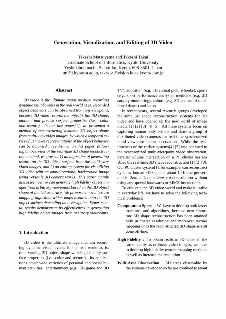
Figure 1 illustrates the hardware organization of ourreal-time active 3D object behavior reconstruction sys-tem. It consists of
• PC cluster: 16 node PCs (dual Pentium III600MHz) are connected through Myrinet, an ul-tra high speed network (full duplex 1.28Gbps).PM library for Myrinet PC clusters[6] allows verylow latency and high speed data transfer, basedon which we can implement efficient parallel pro-cessing on the PC cluster.
Myrinet
Figure 1. PC cluster for real-time active 3Dobject behavior reconstruction system.
• Distributed active video cameras: Among 16,12 PCs have fixed-viewpoint pan-tilt-zoom (FV-PTZ) cameras[7], respectively, for active objecttracking and image capturing. In the FV-PTZcamera, the projection center stays fixed irre-spectively of any camera rotations and zoomings,which greatly facilitates real-time active objecttracking and 3D shape reconstruction.
2.2. Basic Method of 3D Video Generation
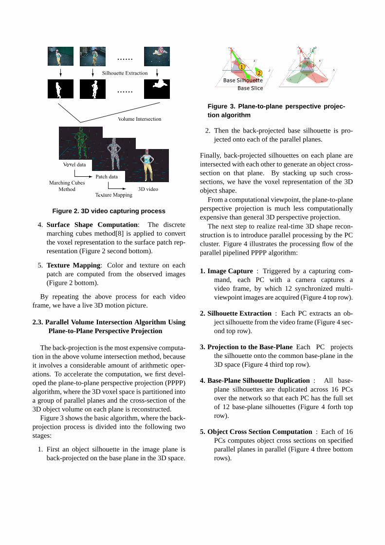
Figure 2 illustrates the basic process of generating a3D video frame in our system:
1. Synchronized Multi-Angle Image Acquisition:A set of multi-viewpoint object images are takensimultaneously by a group of distributed videocameras (Figure 2 top row).
2. Silhouette Extraction: Background subtractionis applied to each captured image to generate aset of multi-viewpoint object silhouettes (Figure2 second top row).
3. Silhouette Volume Intersection: Each silhouetteis back-projected into the common 3D space togenerate a visual cone encasing the 3D object.Then, such 3D cones are intersected with eachother to generate the voxel representation of theobject shape (Figure 2 middle).
�����el data
Marching Cubes
MethodT����
ure Mapping
Patch data
3D video
......
......
����ume Intersection
Silhouette Extraction
Figure 2. 3D video capturing process
4. Surface Shape Computation: The discretemarching cubes method[8] is applied to convertthe voxel representation to the surface patch rep-resentation (Figure 2 second bottom).
5. Texture Mapping: Color and texture on eachpatch are computed from the observed images(Figure 2 bottom).
By repeating the above process for each videoframe, we have a live 3D motion picture.
2.3. Parallel Volume Intersection Algorithm UsingPlane-to-Plane Perspective Projection
The back-projection is the most expensive computa-tion in the above volume intersection method, becauseit involves a considerable amount of arithmetic oper-ations. To accelerate the computation, we first devel-oped the plane-to-plane perspective projection (PPPP)algorithm, where the 3D voxel space is partitioned intoa group of parallel planes and the cross-section of the3D object volume on each plane is reconstructed.
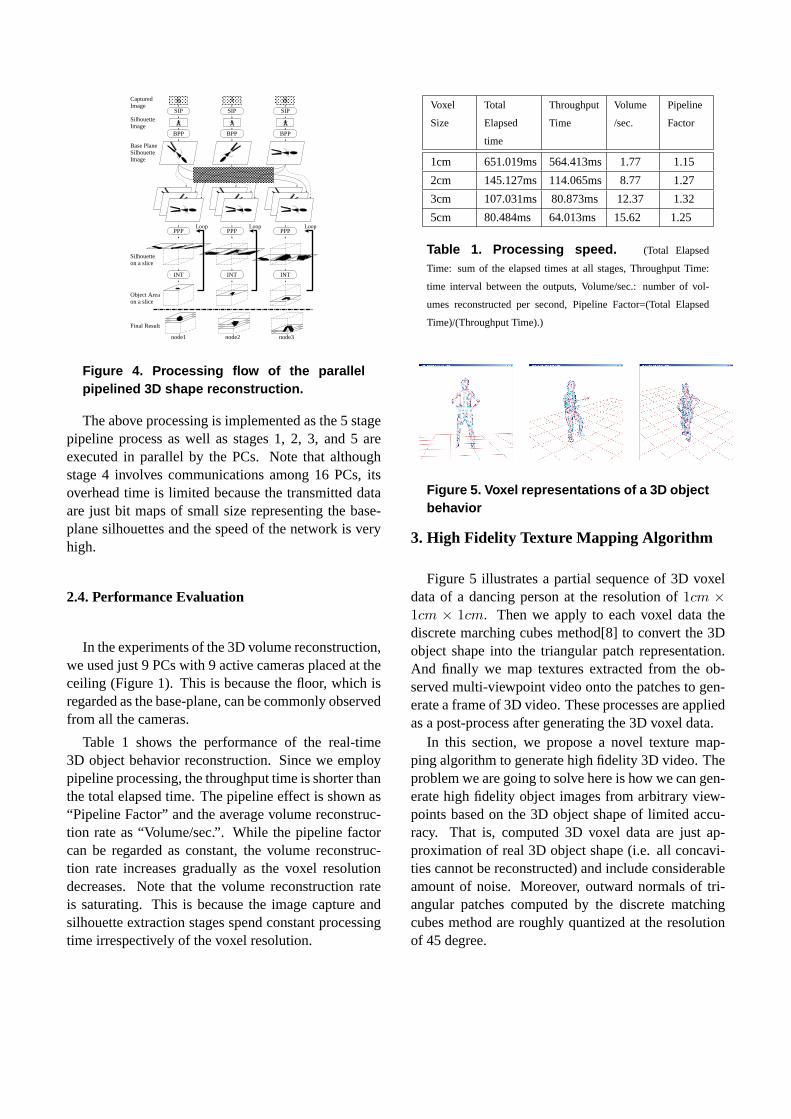
Figure 3 shows the basic algorithm, where the back-projection process is divided into the following twostages:
1. First an object silhouette in the image plane isback-projected on the base plane in the 3D space.
11
22
Base Slice
Base Silhouette
Figure 3. Plane-to-plane perspective projec-tion algorithm
2. Then the back-projected base silhouette is pro-jected onto each of the parallel planes.
Finally, back-projected silhouettes on each plane areintersected with each other to generate an object cross-section on that plane. By stacking up such cross-sections, we have the voxel representation of the 3Dobject shape.
From a computational viewpoint, the plane-to-planeperspective projection is much less computationallyexpensive than general 3D perspective projection.
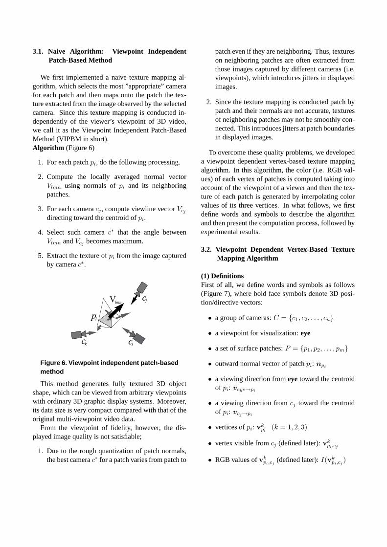
The next step to realize real-time 3D shape recon-struction is to introduce parallel processing by the PCcluster. Figure 4 illustrates the processing flow of theparallel pipelined PPPP algorithm:
1. Image Capture : Triggered by a capturing com-mand, each PC with a camera captures avideo frame, by which 12 synchronized multi-viewpoint images are acquired (Figure 4 top row).
2. Silhouette Extraction : Each PC extracts an ob-ject silhouette from the video frame (Figure 4 sec-ond top row).
3. Projection to the Base-PlaneEach PC projectsthe silhouette onto the common base-plane in the3D space (Figure 4 third top row).
4. Base-Plane Silhouette Duplication: All base-plane silhouettes are duplicated across 16 PCsover the network so that each PC has the full setof 12 base-plane silhouettes (Figure 4 forth toprow).
5. Object Cross Section Computation: Each of 16PCs computes object cross sections on specifiedparallel planes in parallel (Figure 4 three bottomrows).
Communication
SilhouetteImage
Base PlaneSilhouetteImage
Final Result
node1 node2 node3
CapturedImage
Silhouetteon a slice
Loop Loop Loop
Object Areaon a slice
SIP
PPP
BPP
INT
SIP SIP
BPPBPP
PPP PPP
INT INT
Figure 4. Processing flow of the parallelpipelined 3D shape reconstruction.
The above processing is implemented as the 5 stagepipeline process as well as stages 1, 2, 3, and 5 areexecuted in parallel by the PCs. Note that althoughstage 4 involves communications among 16 PCs, itsoverhead time is limited because the transmitted dataare just bit maps of small size representing the base-plane silhouettes and the speed of the network is veryhigh.
2.4. Performance Evaluation
In the experiments of the 3D volume reconstruction,we used just 9 PCs with 9 active cameras placed at theceiling (Figure 1). This is because the floor, which isregarded as the base-plane, can be commonly observedfrom all the cameras.
Table 1 shows the performance of the real-time3D object behavior reconstruction. Since we employpipeline processing, the throughput time is shorter thanthe total elapsed time. The pipeline effect is shown as“Pipeline Factor” and the average volume reconstruc-tion rate as “Volume/sec.”. While the pipeline factorcan be regarded as constant, the volume reconstruc-tion rate increases gradually as the voxel resolutiondecreases. Note that the volume reconstruction rateis saturating. This is because the image capture andsilhouette extraction stages spend constant processingtime irrespectively of the voxel resolution.
Voxel
Size
Total
Elapsed
time
Throughput
Time
Volume
/sec.
Pipeline
Factor
1cm 651.019ms 564.413ms 1.77 1.15
2cm 145.127ms 114.065ms 8.77 1.27
3cm 107.031ms 80.873ms 12.37 1.32
5cm 80.484ms 64.013ms 15.62 1.25
Table 1. Processing speed. (Total Elapsed
Time: sum of the elapsed times at all stages, Throughput Time:
time interval between the outputs, Volume/sec.: number of vol-
umes reconstructed per second, Pipeline Factor=(Total Elapsed
Time)/(Throughput Time).)
Figure 5. Voxel representations of a 3D objectbehavior
3. High Fidelity Texture Mapping Algorithm
Figure 5 illustrates a partial sequence of 3D voxeldata of a dancing person at the resolution of1cm ×1cm × 1cm. Then we apply to each voxel data thediscrete marching cubes method[8] to convert the 3Dobject shape into the triangular patch representation.And finally we map textures extracted from the ob-served multi-viewpoint video onto the patches to gen-erate a frame of 3D video. These processes are appliedas a post-process after generating the 3D voxel data.
In this section, we propose a novel texture map-ping algorithm to generate high fidelity 3D video. Theproblem we are going to solve here is how we can gen-erate high fidelity object images from arbitrary view-points based on the 3D object shape of limited accu-racy. That is, computed 3D voxel data are just ap-proximation of real 3D object shape (i.e. all concavi-ties cannot be reconstructed) and include considerableamount of noise. Moreover, outward normals of tri-angular patches computed by the discrete matchingcubes method are roughly quantized at the resolutionof 45 degree.
3.1. Naive Algorithm: Viewpoint IndependentPatch-Based Method
We first implemented a naive texture mapping al-gorithm, which selects the most ”appropriate” camerafor each patch and then maps onto the patch the tex-ture extracted from the image observed by the selectedcamera. Since this texture mapping is conducted in-dependently of the viewer’s viewpoint of 3D video,we call it as the Viewpoint Independent Patch-BasedMethod (VIPBM in short).Algorithm (Figure 6)
1. For each patchpi, do the following processing.
2. Compute the locally averaged normal vectorVlmn using normals ofpi and its neighboringpatches.
3. For each cameracj , compute viewline vectorVcj
directing toward the centroid ofpi.
4. Select such camerac∗ that the angle betweenVlmn andVcj becomes maximum.
5. Extract the texture ofpi from the image capturedby camerac∗.
Vlmn
pi
ck cl
cj
Figure 6. Viewpoint independent patch-basedmethod
This method generates fully textured 3D objectshape, which can be viewed from arbitrary viewpointswith ordinary 3D graphic display systems. Moreover,its data size is very compact compared with that of theoriginal multi-viewpoint video data.
From the viewpoint of fidelity, however, the dis-played image quality is not satisfiable;
1. Due to the rough quantization of patch normals,the best camerac∗ for a patch varies from patch to
patch even if they are neighboring. Thus, textureson neighboring patches are often extracted fromthose images captured by different cameras (i.e.viewpoints), which introduces jitters in displayedimages.
2. Since the texture mapping is conducted patch bypatch and their normals are not accurate, texturesof neighboring patches may not be smoothly con-nected. This introduces jitters at patch boundariesin displayed images.
To overcome these quality problems, we developeda viewpoint dependent vertex-based texture mappingalgorithm. In this algorithm, the color (i.e. RGB val-ues) of each vertex of patches is computed taking intoaccount of the viewpoint of a viewer and then the tex-ture of each patch is generated by interpolating colorvalues of its three vertices. In what follows, we firstdefine words and symbols to describe the algorithmand then present the computation process, followed byexperimental results.
3.2. Viewpoint Dependent Vertex-Based TextureMapping Algorithm
(1) DefinitionsFirst of all, we define words and symbols as follows(Figure 7), where bold face symbols denote 3D posi-tion/directive vectors:
• a group of cameras:C = {c1, c2, . . . , cn}
• a viewpoint for visualization:eye
• a set of surface patches:P = {p1, p2, . . . , pm}
• outward normal vector of patchpi: npi
• a viewing direction fromeyetoward the centroidof pi: veye→pi
• a viewing direction fromcj toward the centroidof pi: vcj→pi
• vertices ofpi: vkpi
(k = 1, 2, 3)
• vertex visible fromcj (defined later):vkpi,cj
• RGB values ofvkpi,cj
(defined later):I(vkpi,cj
)
Veye -> pi
Npi Vcj -> pi
Vcn -> piVc1 -> pi
Vc2 -> pi
objectpi
cj
cn
c1
c2
Figure 7. Viewpoint and camera position
• a depth buffer ofcj : Bcj
Geometrically this buffer is the same as the imageplane of cameracj . Each pixel ofBcj recordssuch patch ID that is nearest fromcj as well as thedistance to that patch fromcj (Figure 8). When avertex of a patch is mapped onto a pixel, its vertexID is also recorded in that pixel.
cj
pi p
kiiiiiiii
i
i
iiiiii
iiiii
iiii
ii i
kk
kkkkk
k k
kk
kk k
jk kiiiiiii
iiiii
depth
Figure 8. Depth buffer(2) Visible Vertex from Camera cj
The vertex visible fromcj vkpi,cj
is defined as follows.
1. The face of patchpi can be observed from cameracj , if the following condition is satisfied.
npi · vcj→pi < 0 (1)
2. vkpi
is not occluded by any other patches.
Then, we can determinevkpi,cj
by the following pro-cess:
1. First, project all the patches that satisfy equation(1) onto the depth bufferBcj .
2. Then, check the visibility of each vertex using thebuffer. Figure 9 illustrates possible spatial config-urations between a pair of patches: all the vertices
in type (1) and (2) are visible, while in type (5)three vertices of the occluded patch are not vis-ible. In type (3) and (4), only some vertices arevisible.
�����e (1)
�����e (2)
�����e (3)
�����e (4)
�����e (5)
Figure 9. Relations between patches
RGB valuesI(vkpi,cj
) of the visible vertexvkpi,cj
arecomputed by
I(vkpi,cj
) = Icj (v̂pi,cj ), (2)
whereIcj (v) shows RGB values of pixelv on the im-age captured by cameracj , andv̂k
pi,cjdenotes the pixel
position onto which the vertexvkpi,cj
is mapped by theimaging process of cameracj .
(3) Algorithm
1. Compute RGB values of all vertices visible fromeach camera inC = {c1, c2, . . . , cn}.
2. Specify the viewpointeye.3. For each surface patchpi ∈ P , do 4 to 9.
4. If veye→pi · npi < 0, then do 5 to 9.
5. Compute weightwcj = (vcj→pi · veye→pi)m,
wherem is a weighting factor to be specified apriori.
6. For each vertexvkpi
(k = 1, 2, 3) of patchpi, do7 to 8.
7. Compute the normalized weight forvkpi
by
w̄kcj
=wk
cj∑l w
kcl
. (3)
Here, ifvkpi
is visible from cameracj , thenwkcj
=wcj , elsewk
cj= 0.
8. Compute the RGB valuesI(vkpi
) of vkpi
by
I(vkpi
) =n∑
j=1
w̄kcj
I(vkpi,cj
) (4)
9. Generate the texture of patchpi by linearly inter-polating RGB values of its vertices. To be moreprecise, depending on the number of vertices withnon-zero RGB values, the following processing isconducted:
• 3.Generate RGB values at each point on thepatch by linearly interpolating the RGB val-ues of 3 vertices .
• 2.Compute mean values of the RGB values ofthe 2 vertices, which is regarded as those ofthe other vertex. Then apply the linear in-terpolation on the patch.
• 1.Paint the patch by the RGB values of thevertex.
• 0.Texture of the patch is not generated:painted by black for example.
By the above process, an image representing an ar-bitrary view (i.e fromeye) of the 3D object is gener-ated.
3.3. Performance Evaluation
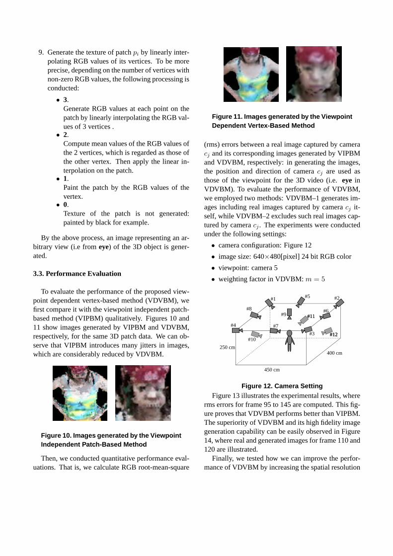
To evaluate the performance of the proposed view-point dependent vertex-based method (VDVBM), wefirst compare it with the viewpoint independent patch-based method (VIPBM) qualitatively. Figures 10 and11 show images generated by VIPBM and VDVBM,respectively, for the same 3D patch data. We can ob-serve that VIPBM introduces many jitters in images,which are considerably reduced by VDVBM.
Figure 10. Images generated by the ViewpointIndependent Patch-Based Method
Then, we conducted quantitative performance eval-uations. That is, we calculate RGB root-mean-square
Figure 11. Images generated by the ViewpointDependent Vertex-Based Method
(rms) errors between a real image captured by cameracj and its corresponding images generated by VIPBMand VDVBM, respectively: in generating the images,the position and direction of cameracj are used asthose of the viewpoint for the 3D video (i.e.eye inVDVBM). To evaluate the performance of VDVBM,we employed two methods: VDVBM–1 generates im-ages including real images captured by cameracj it-self, while VDVBM–2 excludes such real images cap-tured by cameracj . The experiments were conductedunder the following settings:
• camera configuration: Figure 12
• image size: 640×480[pixel] 24 bit RGB color
• viewpoint: camera 5
• weighting factor in VDVBM:m = 5
450 cm
400 cm250 cm
#1 #5
#8
#7
#6
#12#12
#11#11
#10
#9
#2
#3
#4
Figure 12. Camera SettingFigure 13 illustrates the experimental results, where
rms errors for frame 95 to 145 are computed. This fig-ure proves that VDVBM performs better than VIPBM.The superiority of VDVBM and its high fidelity imagegeneration capability can be easily observed in Figure14, where real and generated images for frame 110 and120 are illustrated.
Finally, we tested how we can improve the perfor-mance of VDVBM by increasing the spatial resolution
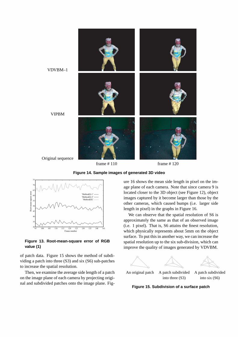
VDVBM–1
VIPBM
Original sequenceframe # 110 frame # 120
Figure 14. Sample images of generated 3D video
30
35
40
45
50
55
60
65
70
75
95 100 105 110 115 120 125 130 135 140 145
Ro
ot-
mea
n-s
qu
are
erro
r
Frame number
’Method(I)-1’
’Method(I)-2’
’Method(II)’
Figure 13. Root-mean-square error of RGBvalue (1)
of patch data. Figure 15 shows the method of subdi-viding a patch into three (S3) and six (S6) sub-patchesto increase the spatial resolution.
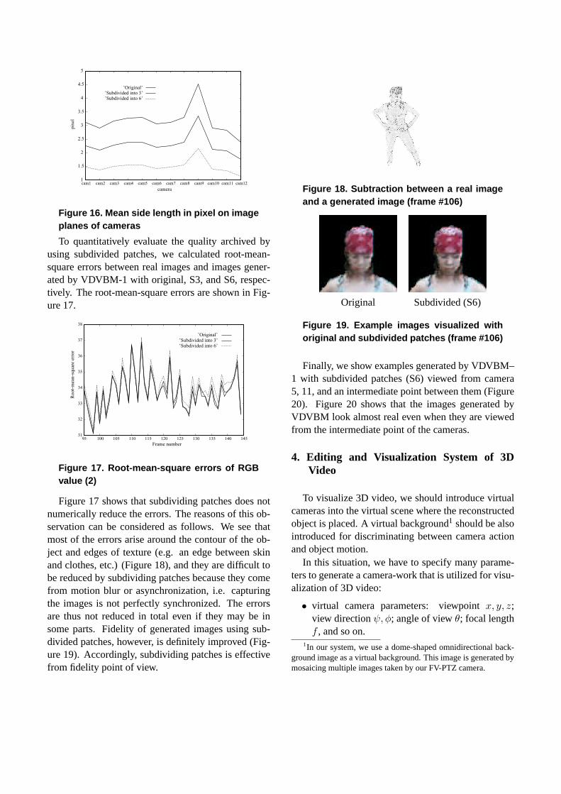
Then, we examine the average side length of a patchon the image plane of each camera by projecting origi-nal and subdivided patches onto the image plane. Fig-
ure 16 shows the mean side length in pixel on the im-age plane of each camera. Note that since camera 9 islocated closer to the 3D object (see Figure 12), objectimages captured by it become larger than those by theother cameras, which caused bumps (i.e. larger sidelength in pixel) in the graphs in Figure 16.
We can observe that the spatial resolution of S6 isapproximately the same as that of an observed image(i.e. 1 pixel). That is, S6 attains the finest resolution,which physically represents about 5mm on the objectsurface. To put this in another way, we can increase thespatial resolution up to the six sub-division, which canimprove the quality of images generated by VDVBM.
An original patch A patch subdivided A patch subdividedinto three (S3) into six (S6)
Figure 15. Subdivision of a surface patch
1
1.5
2
2.5
3
3.5
4
4.5
5
cam1 cam2 cam3 cam4 cam5 cam6 cam7 cam8 cam9 cam10 cam11 cam12
pix
el
camera
’Original’’Subdivided into 3’’Subdivided into 6’
Figure 16. Mean side length in pixel on imageplanes of cameras
To quantitatively evaluate the quality archived byusing subdivided patches, we calculated root-mean-square errors between real images and images gener-ated by VDVBM-1 with original, S3, and S6, respec-tively. The root-mean-square errors are shown in Fig-ure 17.
31
32
33
34
35
36
37
38
95 100 105 110 115 120 125 130 135 140 145
Root-
mea
n-s
quar
e er
ror
Frame number
’Original’’Subdivided into 3’’Subdivided into 6’
Figure 17. Root-mean-square errors of RGBvalue (2)
Figure 17 shows that subdividing patches does notnumerically reduce the errors. The reasons of this ob-servation can be considered as follows. We see thatmost of the errors arise around the contour of the ob-ject and edges of texture (e.g. an edge between skinand clothes, etc.) (Figure 18), and they are difficult tobe reduced by subdividing patches because they comefrom motion blur or asynchronization, i.e. capturingthe images is not perfectly synchronized. The errorsare thus not reduced in total even if they may be insome parts. Fidelity of generated images using sub-divided patches, however, is definitely improved (Fig-ure 19). Accordingly, subdividing patches is effectivefrom fidelity point of view.
Figure 18. Subtraction between a real imageand a generated image (frame #106)
Original Subdivided (S6)
Figure 19. Example images visualized withoriginal and subdivided patches (frame #106)
Finally, we show examples generated by VDVBM–1 with subdivided patches (S6) viewed from camera5, 11, and an intermediate point between them (Figure20). Figure 20 shows that the images generated byVDVBM look almost real even when they are viewedfrom the intermediate point of the cameras.
4. Editing and Visualization System of 3DVideo
To visualize 3D video, we should introduce virtualcameras into the virtual scene where the reconstructedobject is placed. A virtual background1 should be alsointroduced for discriminating between camera actionand object motion.
In this situation, we have to specify many parame-ters to generate a camera-work that is utilized for visu-alization of 3D video:
• virtual camera parameters: viewpointx, y, z;view directionψ, φ; angle of viewθ; focal lengthf , and so on.
1In our system, we use a dome-shaped omnidirectional back-ground image as a virtual background. This image is generated bymosaicing multiple images taken by our FV-PTZ camera.
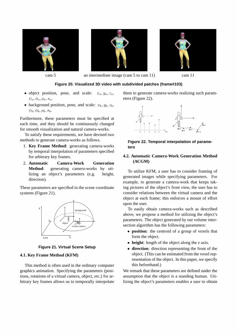
cam 5 an intermediate image (cam 5 to cam 11) cam 11
Figure 20. Visualized 3D video with subdivided patches (frame#103)
• object position, pose, and scale:xo, yo, zo,ψo, φo, ρo, so.
• background position, pose, and scale:xb, yb, zb,ψb, φb, ρb, sb.
Furthermore, these parameters must be specified ateach time, and they should be continuously changedfor smooth visualization and natural camera-works.
To satisfy these requirements, we have devised twomethods to generate camera-works as follows.
1. Key Frame Method: generating camera-worksby temporal interpolation of parameters specifiedfor arbitrary key frames.
2. Automatic Camera-Work GenerationMethod: generating camera-works by uti-lizing an object’s parameters (e.g. height,direction).
These parameters are specified in the scene coordinatesystems (Figure 21).
scene
virtual camera
background
object
x
y
z
Figure 21. Virtual Scene Setup
4.1. Key Frame Method (KFM)
This method is often used in the ordinary computergraphics animation. Specifying the parameters (posi-tions, rotations of a virtual camera, object, etc.) for ar-bitrary key frames allows us to temporally interpolate
them to generate camera-works realizing such param-eters (Figure 22).
timet0 t1 t2 tn-1 tn
p(0)p(1)
p(2)p(n-1)
p(n)
Figure 22. Temporal interpolation of parame-ters
4.2. Automatic Camera-Work Generation Method(ACGM)
To utilize KFM, a user has to consider framing ofgenerated images while specifying parameters. Forexample, to generate a camera-work that keeps tak-ing pictures of the object’s front view, the user has toconsider relations between the virtual camera and theobject at each frame; this enforces a mount of effortupon the user.
To easily obtain camera-works such as describedabove, we propose a method for utilizing the object’sparameters. The object generated by our volume inter-section algorithm has the following parameters:• position: the centroid of a group of voxels that
form the object.• height: length of the object along the z axis.• direction: direction representing the front of the
object. (This can be estimated from the voxel rep-resentation of the object. In this paper, we specifythis beforehand.)
We remark that these parameters are defined under theassumption that the object is a standing human. Uti-lizing the object’s parameters enables a user to obtain
arbitrary camera-works. That is, the user has only tospecify
1. framing of a picture : close up, middle shot, fullshot, etc., and
2. appearance of the object from the virtual cam-era: front, back, etc.
Once the framing of a picture and the appearance ofthe object are specified, the parameters of the virtualcamera are computed as follows:
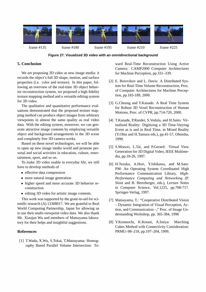
• distance between the virtual camera and theobject d (Figure 23):
d =r · h
2 tan θ2
, (5)
whereh is the height of the object.θ is an angle ofview, which is arbitrarily specified.r is the ratioof a size of an image to a size of the renderedobject, and it is defined as follows:
– r = 1.0: full shot,– r = 0.7: knee shot,– r = 0.5: middle shot,– r = 0.3: close shot, and– r = 0.2: close up.
(1-r)h
hr h
d
θ
Figure 23. Relation between a virtual cameraand an object (I)
• position of the virtual camera (xc, yc, zc) :
xc = d cosφ cos(ψ + δ) + xp
yc = d cosφ sin(ψ + δ) + yp
zc = d sinφ + zp
, (6)
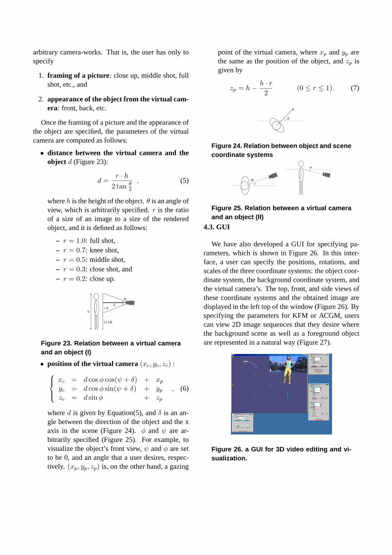
whered is given by Equation(5), andδ is an an-gle between the direction of the object and the xaxis in the scene (Figure 24).φ and ψ are ar-bitrarily specified (Figure 25). For example, tovisualize the object’s front view,ψ andφ are setto be 0, and an angle that a user desires, respec-tively. (xp, yp, zp) is, on the other hand, a gazing
point of the virtual camera, wherexp andyp arethe same as the position of the object, andzp isgiven by
zp = h− h · r2
(0 ≤ r ≤ 1). (7)
δ
Figure 24. Relation between object and scenecoordinate systems
ψ
φ
Figure 25. Relation between a virtual cameraand an object (II)
4.3. GUI
We have also developed a GUI for specifying pa-rameters, which is shown in Figure 26. In this inter-face, a user can specify the positions, rotations, andscales of the three coordinate systems: the object coor-dinate system, the background coordinate system, andthe virtual camera’s. The top, front, and side views ofthese coordinate systems and the obtained image aredisplayed in the left top of the window (Figure 26). Byspecifying the parameters for KFM or ACGM, userscan view 2D image sequences that they desire wherethe background scene as well as a foreground objectare represented in a natural way (Figure 27).
Figure 26. a GUI for 3D video editing and vi-sualization.
frame #135 frame #180 frame #195 frame #210 frame #225
Figure 27. Visualized 3D video with an omnidirectional background
5. Conclusion
We are proposing 3D video as new image media: itrecords the object’s full 3D shape, motion, and surfaceproperties (i.e. color and texture). In this paper, fol-lowing an overview of the real-time 3D object behav-ior reconstruction system, we proposed a high fidelitytexture mapping method and a versatile editing systemfor 3D video.
The qualitative and quantitative performance eval-uations demonstrated that the proposed texture map-ping method can produce object images from arbitraryviewpoints in almost the same quality as real videodata. With the editing system, moreover, we can gen-erate attractive image contents by employing versatileobject and background arrangements in the 3D sceneand completely free 3D camera-works.
Based on these novel technologies, we will be ableto open up new image media world and promote per-sonal and social activities in education, culture, enter-tainment, sport, and so on.
To make 3D video usable in everyday life, we stillhave to develop methods of
• effective data compression
• more natural image generation
• higher speed and more accurate 3D behavior re-construction
• editing 3D video for artistic image contents.
This work was supported by the grant-in-aid for sci-entific research (A) 13308017. We are grateful to RealWorld Computing Partnership, Japan for allowing usto use their multi-viewpoint video data. We also thankMr. Xiaojun Wu and members of Matsuyama labora-tory for their helps and insightful suggestions.
References
[1] T.Wada, X.Wu, S.Tokai, T.Matsuyama: Homog-raphy Based Parallel Volume Intersection: To-
ward Real-Time Reconstruction Using ActiveCamera: CAMP2000 Computer Architecturesfor Machine Perception, pp.331–339.
[2] E. Borovikov and L. Davis: A Distributed Sys-tem for Real-Time Volume Reconstruction, Proc.of Computer Architectures for Machine Percep-tion, pp.183-189, 2000.
[3] G.Cheung and T.Kanade: A Real Time Systemfor Robust 3D Voxel Reconstruction of HumanMotions, Proc. of CVPR, pp.714-720, 2000.
[4] T.Kanade, P.Rander, S.Vedula, and H.Saito: Vir-tualized Reality: Digitizing a 3D Time-VaryingEvent as is and in Real Time, in Mixed Reality(Y.Ohta and H.Tamura eds.), pp.41-57, Ohmsha,1999.
[5] S.Moezzi, L.Tai, and P.Gerard: Virtual ViewGeneration for 3D Digital Video, IEEE Multime-dia, pp.18-26, 1997.
[6] H.Tezuka, A.Hori, Y.Ishikawa, and M.Sato:PM: An Operating System Coordinated HighPerformance Communication Library,High-Performance Computing and Networking(P.Sloot and B. Hertzberger, eds.), Lecture Notesin Computer Science, Vol.1225, pp.708-717.Springer-Verlag, 1997.
[7] Matsuyama, T.: “Cooperative Distributed Vision– Dynamic Integration of Visual Perception, Ac-tion, and Communication –,” Proc. of Image Un-derstanding Workshop, pp. 365-384, 1998
[8] Y.Kenmochi, K.Kotani, A.Imiya: MarchingCubes Method with Connectivity Consideration:PRMU–98–218, pp.197–204, 1999.


![Towards Automata Diagram Drawings - DCCnam/web/resources/docs/teseAA.pdfGUItar [FAd10b] is a graphical environment tool for nite automata visualization and editing. The Figure 1.1](https://static.fdocuments.us/doc/165x107/5e719dc306793a7f293e90de/towards-automata-diagram-drawings-namwebresourcesdocsteseaapdf-guitar-fad10b.jpg)