
Generation of an isolated attosecond pulse via current ...
9
Generation of an isolated attosecond pulse via current modulation induced by a chirped laser pulse in an x-ray free-electron laser SANDEEP KUMAR, 1 JAEYU LEE, 2 MIN SUP HUR, 1,4 AND MOSES CHUNG 1,3 1 Department of Physics, Ulsan National Institute of Science and Technology (UNIST), Ulsan 44919, South Korea 2 Pohang Accelerator Laboratory, Pohang 790-784, South Korea 3 e-mail: [email protected] 4 e-mail: [email protected] Received 26 September 2017; revised 6 March 2018; accepted 8 March 2018; posted 13 March 2018 (Doc. ID 307943); published 30 March 2018 Aiming for the future upgrade of a hard x-ray beamline at the Pohang accelerator laboratory x-ray free-electron laser (PAL-XFEL), we first analyze the scheme recently proposed for the attosecond-terawatt (TW) x-ray pulse [Phys. Rev. Lett. 110, 084801 (2013)]. An x-ray pulse with 32 attosecond full-width half maximum (FWHM) pulse duration and ∼4 TW in power is shown in simulations using the PAL-XFEL parameters. Furthermore, to remove neighboring radiation pulses and to generate an isolated attosecond-TW x-ray pulse, the role of optical laser frequency chirp is examined on the electron beam current modulation as well as on the x-ray pulse gen- eration in the undulator. Our simulations show an isolated x-ray pulse with 42 attosecond FWHM pulse duration and ∼3.5 TW in power for the optimal frequency chirp of a 400 nm optical laser. Recently, in a simpler method [J. Synchrotron Radiat. 23, 1273 (2016)] and [Phys. Rev. ST Accel. Beams 8, 040701 (2005)], using a frequency- chirped optical laser and the electron beam delays in between undulator sections, it has been reported that an isolated attosecond-TW x-ray pulse can be obtained at the undulator end. For optimal chirp in this simple setup, we show 50 attosecond FWHM pulse duration and ∼3 TW in power with ∼7.5 × 10 10 photons per pulse at 0.1 nm radiation wavelength. Generation of such inherently synchronized, powerful single attosecond x-ray pulses at PAL-XFEL will be advantageous to the pump-probe experiments in the study of ultrafast dynamics. © 2018 Optical Society of America OCIS codes: (140.2600) Free-electron lasers (FELs); (140.7215) Undulator radiation; (140.7240) UV, EUV, and X-ray lasers; (320.1590) Chirping; (320.5520) Pulse compression; (340.7470) X-ray mirrors. https://doi.org/10.1364/JOSAB.35.000A75 1. INTRODUCTION X-ray free electron lasers (XFELs) with ultrashort pulse duration and ultrahigh brilliance will open exciting prospects for high-field attosecond science and high-energy density phys- ics (HEDP), as the short and intense x-ray pulses can create unique initial states of matter. The motion of electrons that occurs on a time scale of a few attoseconds (10 -18 s) or less has not been accessible by direct experimental methods until very recently. Extreme-ultraviolet (XUV) coherent light pulses with durations of a few tens of attoseconds can be pro- duced using high-order harmonic generation (HHG) [1–5]. However, the applications of the attosecond sources have so far been limited due to the low photon flux and the complexity of the tools, particularly for the generation of isolated attosec- ond pulses (IAPs). X-ray free electron laser sources based on a self-amplified spontaneous emission (SASE) scheme presently surpass the HHG sources in reducing the wavelength (by approximately two orders of magnitude), peak brightness, and spatial coher- ence [6–10]. Moreover, the self-seeding [9,11] improves the temporal coherence, which further leads to the enhanced pho- ton flux and brilliance. The shortest wavelength and the high brightness of the XFELs make them a promising candidate for progressing to high-power attosecond x-ray pulses, which has attracted much attention in the XFEL user community. However, due to the large electron bunch duration, FEL facili- ties have aimed only for the femtosecond regime; generating high-power attosecond pulses in XFELs has been a formidable challenge. Many potential methods (mostly theoretical), have been developed for shortening the duration of the XFEL pulses to sub-femtosecond to zeptosecond levels [12–24]. In these schemes, the electron beam properties are manipulated by short laser pulses or by other means before entering the undulator. In view of the electron beam manipulation, a slotted foil method Research Article Vol. 35, No. 4 / April 2018 / Journal of the Optical Society of America B A75 0740-3224/18/040A75-09 Journal © 2018 Optical Society of America
Transcript of Generation of an isolated attosecond pulse via current ...

Generation of an isolated attosecond pulse viacurrent modulation induced by a chirped laserpulse in an x-ray free-electron laserSANDEEP KUMAR,1 JAEYU LEE,2 MIN SUP HUR,1,4 AND MOSES CHUNG1,3
1Department of Physics, Ulsan National Institute of Science and Technology (UNIST), Ulsan 44919, South Korea2Pohang Accelerator Laboratory, Pohang 790-784, South Korea3e-mail: [email protected]: [email protected]
Received 26 September 2017; revised 6 March 2018; accepted 8 March 2018; posted 13 March 2018 (Doc. ID 307943); published 30 March 2018
Aiming for the future upgrade of a hard x-ray beamline at the Pohang accelerator laboratory x-ray free-electronlaser (PAL-XFEL), we first analyze the scheme recently proposed for the attosecond-terawatt (TW) x-ray pulse[Phys. Rev. Lett. 110, 084801 (2013)]. An x-ray pulse with 32 attosecond full-width half maximum (FWHM)pulse duration and ∼4 TW in power is shown in simulations using the PAL-XFEL parameters. Furthermore, toremove neighboring radiation pulses and to generate an isolated attosecond-TW x-ray pulse, the role of opticallaser frequency chirp is examined on the electron beam current modulation as well as on the x-ray pulse gen-eration in the undulator. Our simulations show an isolated x-ray pulse with 42 attosecond FWHM pulse durationand ∼3.5 TW in power for the optimal frequency chirp of a 400 nm optical laser. Recently, in a simpler method[J. Synchrotron Radiat. 23, 1273 (2016)] and [Phys. Rev. ST Accel. Beams 8, 040701 (2005)], using a frequency-chirped optical laser and the electron beam delays in between undulator sections, it has been reported that anisolated attosecond-TW x-ray pulse can be obtained at the undulator end. For optimal chirp in this simple setup,we show 50 attosecond FWHM pulse duration and ∼3 TW in power with ∼7.5 × 10¹⁰ photons per pulse at0.1 nm radiation wavelength. Generation of such inherently synchronized, powerful single attosecond x-ray pulsesat PAL-XFEL will be advantageous to the pump-probe experiments in the study of ultrafast dynamics. © 2018
Optical Society of America
OCIS codes: (140.2600) Free-electron lasers (FELs); (140.7215) Undulator radiation; (140.7240) UV, EUV, and X-ray lasers;
(320.1590) Chirping; (320.5520) Pulse compression; (340.7470) X-ray mirrors.
https://doi.org/10.1364/JOSAB.35.000A75
1. INTRODUCTION
X-ray free electron lasers (XFELs) with ultrashort pulseduration and ultrahigh brilliance will open exciting prospectsfor high-field attosecond science and high-energy density phys-ics (HEDP), as the short and intense x-ray pulses can createunique initial states of matter. The motion of electrons thatoccurs on a time scale of a few attoseconds (10−18 s) or lesshas not been accessible by direct experimental methods untilvery recently. Extreme-ultraviolet (XUV) coherent lightpulses with durations of a few tens of attoseconds can be pro-duced using high-order harmonic generation (HHG) [1–5].However, the applications of the attosecond sources have sofar been limited due to the low photon flux and the complexityof the tools, particularly for the generation of isolated attosec-ond pulses (IAPs).
X-ray free electron laser sources based on a self-amplifiedspontaneous emission (SASE) scheme presently surpass the
HHG sources in reducing the wavelength (by approximatelytwo orders of magnitude), peak brightness, and spatial coher-ence [6–10]. Moreover, the self-seeding [9,11] improves thetemporal coherence, which further leads to the enhanced pho-ton flux and brilliance. The shortest wavelength and the highbrightness of the XFELs make them a promising candidatefor progressing to high-power attosecond x-ray pulses, whichhas attracted much attention in the XFEL user community.However, due to the large electron bunch duration, FEL facili-ties have aimed only for the femtosecond regime; generatinghigh-power attosecond pulses in XFELs has been a formidablechallenge. Many potential methods (mostly theoretical), havebeen developed for shortening the duration of the XFEL pulsesto sub-femtosecond to zeptosecond levels [12–24]. In theseschemes, the electron beam properties are manipulated by shortlaser pulses or by other means before entering the undulator. Inview of the electron beam manipulation, a slotted foil method
Research Article Vol. 35, No. 4 / April 2018 / Journal of the Optical Society of America B A75
0740-3224/18/040A75-09 Journal © 2018 Optical Society of America
[13] is used to reduce the x-ray pulse duration. According tothis method, a slotted foil inserted in the middle of the bunch-compressor of the linac selectively lets in only an unspoiled partof the electron beam for radiation generation [21]. In the cur-rent enhanced SASE (ESASE) [15], the electron peak current isenhanced in a short slice by manipulating the longitudinalphase by an external few-cycle infrared laser pulse, leadingto the generation of attosecond radiation pulses. However, finalpulse length generated in ESASE is limited by the FEL slippagelength, which is of the order of a few hundred attoseconds.Besides, the length of the x-ray pulse can be controlled byreducing the charge of the electron beam, which has also beenexperimentally demonstrated [20]. Overall, in these schemes,the radiation power and pulse durations are not enough,being of the order of gigawatt and sub-femtosecond ranges,respectively.
To follow the electronic motions and to allow the investi-gation of the events that have not been explored previously inx-ray nonlinear science, new ideas need to be developed togenerate high-power attosecond x-ray pulses in FEL. In viewof generating the shortest pulse, the mode-locking concept ap-plied to SASE FELs has been efficient in generating attosecondpulse trains (APTs) with gigawatt power [22,23]. Recently,using a slotted foil in combination with the mode locked-afterburner scheme [24], the length of the attosecond pulsetrain was reduced to a single lobe of envelope, where the phaseof each attosecond pulse inside the envelope is constant, poten-tially offering benefits to the experimental users.
Generating an intense, isolated attosecond pulse (IAP) hasbeen technically challenging in XFEL. Recently, Tanaka [25]proposed a mechanism for generating an attosecond-terawatt(TW) x-ray pulse by employing the combination of a slottedfoil [13], current ESASE [15], x-ray beam delay, and the de-layed electron beam from the x-ray between undulator mod-ules. In a similar work [26], a slotted foil with multipleslots is used for effective chopping of an electron bunch intomany current spikes with the emittance being preserved, andthen the electron beam is delayed between undulator modulesfor the amplification of the radiation. In another work, Kumaret al. [27] proposed a new mechanism for generation of atto-second-TW x-ray pulses in XFEL controlled by a few-cycle in-frared (IR) pulse, where one dominant current spike in anelectron bunch is used repeatedly to amplify the seeded radi-ation to a TW level. Recently, in a simple method [28,29], anisolated attosecond-TW x-ray pulse is demonstrated in simu-lation by creating multiple current spikes having unequal
spacing variation by a frequency-chirped optical laser used inthe ESASE section. In this way, only the target radiation spikecan get amplified in the undulator while the growth of neigh-boring radiation spikes is suppressed due to the misalignmentwith the rest of the current spikes.
In this paper, we examine the schemes proposed in[25,28,29] using PAL-XFEL parameters. We show the possibil-ity of attosecond-TW pulse generation at hard x-ray beamline.To generate a single IAP, which is essential for the pump-probeexperiments, the role of the optical laser frequency chirps isstudied on the current modulation after the ESASE section.The chirped laser pulse can be obtained by the chirped pulseamplification (CPA) technique [30], where a laser pulse isstretched out temporally and spectrally prior to amplificationup to the petawatt level. The paper is organized as follows.In Section 2, the proposed scheme and its working principleare discussed. In Section 3, the simulation results of the atto-second pulse generation are presented based on the PAL-XFELparameters. For experimental realization of the scheme, prob-able specifications of x-ray delay system and electron beamdelays are discussed. The key issues of the synchronizationand timing jitter are also discussed. Finally, in Section 4,our conclusion is given.
2. METHOD AND MECHANISM
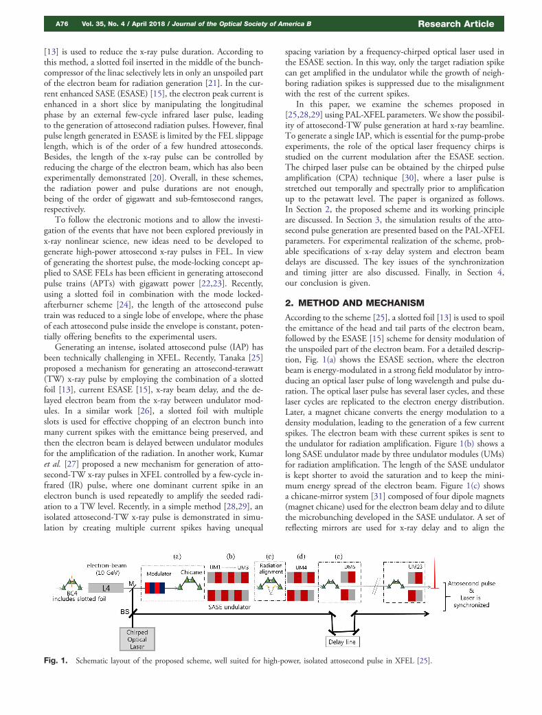
According to the scheme [25], a slotted foil [13] is used to spoilthe emittance of the head and tail parts of the electron beam,followed by the ESASE [15] scheme for density modulation ofthe unspoiled part of the electron beam. For a detailed descrip-tion, Fig. 1(a) shows the ESASE section, where the electronbeam is energy-modulated in a strong field modulator by intro-ducing an optical laser pulse of long wavelength and pulse du-ration. The optical laser pulse has several laser cycles, and theselaser cycles are replicated to the electron energy distribution.Later, a magnet chicane converts the energy modulation to adensity modulation, leading to the generation of a few currentspikes. The electron beam with these current spikes is sent tothe undulator for radiation amplification. Figure 1(b) shows along SASE undulator made by three undulator modules (UMs)for radiation amplification. The length of the SASE undulatoris kept shorter to avoid the saturation and to keep the mini-mum energy spread of the electron beam. Figure 1(c) showsa chicane-mirror system [31] composed of four dipole magnets(magnet chicane) used for the electron beam delay and to dilutethe microbunching developed in the SASE undulator. A set ofreflecting mirrors are used for x-ray delay and to align the
Fig. 1. Schematic layout of the proposed scheme, well suited for high-power, isolated attosecond pulse in XFEL [25].
A76 Vol. 35, No. 4 / April 2018 / Journal of the Optical Society of America B Research Article

electron beam and x-ray beam mutually. The electron beam isdelayed in such a way that the leading spike of the radiation actsas a seed to the trailing current spikes. Figure 1(d) shows thenext stage undulator having two UMs used for the amplifica-tion of the seed pulse. For FEL amplification, the seed pulsealways needs a fresh bunch of electrons after one gain lengthof the amplification. Figure 1(e) shows a small magnet chicanefollowed by a small undulator section (only 1 UM). A smallchicane is used to delay the electrons by the laser wavelengthλL to align the radiation spike to the second current spike. Thesection in Fig. 1(e) is used for several stages in the downstreamfor repeated electron beam delays and repeated amplification ofthe selected radiation pulse to obtain an attosecond x-ray pulse.However, this scheme does not show an isolated attosecondx-ray pulse.
To get an isolated x-ray pulse, the frequency chirp in themodulation laser is introduced. This generates the currentspikes with unequal spacing as shown in Fig. 2(a). Figure 2(b)shows the radiation profile after first SASE undulator amplifi-cation [see Fig. 1(b)], and Fig. 2(c) shows the radiation profiledelayed with respect to the current profile by a chicane-mirrorsection [see Fig. 1(c)] to align the selected radiation spike withthe tail current spike.
A. Without Slotted Foil and Radiation AlignmentSection
Because of the complexity of this scheme [25] and the stringentrequirement for x-ray delay system (though soon to be availablewith the rapid advance of the technology), recently, a simplemethod [28,29] was proposed for attosecond-TW x-ray pulsegeneration. According to the method, using a frequency-chirped laser in the ESASE section and the electron beamdelays in between undulator modules, an isolated attosecondx-ray pulse can be obtained at the end of the undulator. Thismethod does not require the slotted foil and the chicane-mirrorsystem (as shown in Fig. 1).
3. SIMULATION RESULTS
To study the feasibility of the attosecond beamline at thePohang accelerator laboratory (PAL)-XFEL [10] and producingintense IAP in the hard x-ray region, we present simulationresults based on the PAL-XFEL parameters, currently underoperation.
First, a 10 GeV, 200 pico-coulombs (pC) electron beamwith an average current of 3.5 kilo-ampere (kA) and an un-cor-related energy spread of 1.0 × 10⁻⁴ is chosen. The detailedparameters of the electron beam used in the ESASE sectionand the undulator of the PAL-XFEL are presented in Table 1.
A. Effects of the Slotted Foil and ESASE Section onthe Current Profile of the 10 GeV Electron Beam
The net current profile after the slotted foil can be expressed asa combination of two terms [25],
I�s� � �I 0�s� � Iu�s��: (1)
The first term, I0�s�, represents the electrons not scatteredby the slotted foil and contributes to the lasing. It can beexpressed as the Gaussian function with the standarddeviation σf ,
I 0�s� �1ffiffiffiffiffi2π
pσf
Zs2
s1I�s 0� exp�−�s − s 0�2∕2σ2f �ds 0,
where s is the longitudinal coordinate of the electron bunch,and the longitudinal positions s1 and s2 define the slot widthof the foil. The second term, I u�s�, corresponds to the scatteredelectrons by the slotted foil and does not contribute to thelasing,
I u�s� � �I�s� − I 0�s��:After passing through the ESASE section, the current profile
is given by [25],
I s � �I0�s� � I u�s��E�s�: (2)
Here, E�s� is the periodic current-enhancement factor dueto the ESASE section, expressed as [25]
Fig. 2. (a) Current spikes with unequal spacing generated by achirped laser pulse. (b) Radiation pulse profile after SASE undulatoramplification. (c) Delayed radiation pulse profile by a chicane-mirrorsection.
Table 1. Attosecond-TW PAL-XFEL Parameters
Parameters: Hard x-ray FEL
Electron beam energy 10 GeVBeam charge 200 pCCurrent 3.5 kANormalized emittance (ϵnx,ny) 0.2 μm-radBeam energy spread (σγ∕γ) 1.0 × 10⁻⁴ESASE Parameters:Laser power (P) 13.6 GWLaser wavelength (λL) 400 nmLaser pulse duration (τ) 40 fsLaser waist size (w0) 250 μmWiggler period (λw) 50 cmWiggler length (L) 1 mUndulator parameters:Undulator period length (λu) 2.6 cmUndulator parameter (K w) 1.9728Radiation wavelength (λr ) 0.1 nm
Research Article Vol. 35, No. 4 / April 2018 / Journal of the Optical Society of America B A77
E�s� �Xj
eBa
1
1� 16B2��s∕λL� − �θ∕2π� − j�2,
with a � 1� B1∕e , B � Δγ∕σγ , where Δγ represents the in-duced energy modulation that exceeds the uncorrelated energyspread σγ of the electron bunch. θ represents the time-jitterbetween the electron bunch and the optical laser at the entranceof the undulator and varies between −π and π. Following theabove equations, we obtain the current profiles at three differ-ent locations. Figure 3 shows the current profile before (blueline) and after (red line) the slotted foil. The black dot line is thespoiled part of the current profile. The lasing width is given bys1 � −5 μm to s2 � 4 μm, and σf � 1 μm has been assumed.This current profile after the slotted foil is obtained by Eq. (1).Compared to the original Gaussian profile before the slottedfoil, the temporal window of lasing is chopped by the slottedfoil; however, the boundary is not sharply trimmed, and a fringeregion exists whose width corresponds to σf . In Section 3.B, wediscuss the attosecond pulse generation using the equallyspaced current spikes of the electron beam.
B. Attosecond-TW Pulse Generation in the HardX-Ray Regime
To demonstrate the attosecond-TW pulse generation in thehard x-ray regime, first we modulate the current by employingan ESASE section in between the linac and the undulatorsections. For the ESASE section, wiggler parameters (wigglerperiod and magnetic field) can be optimized by using therelation, λL � �λw∕2γ2��1� K 2
w∕2�, where λL is the laserwavelength, λw is the wiggler period, and K w � eB0∕mkc isthe wiggler parameter. Here, B0 is the magnetic field in tesla,and k � 2π∕λw. All the simulation parameters are shown inTable 1.
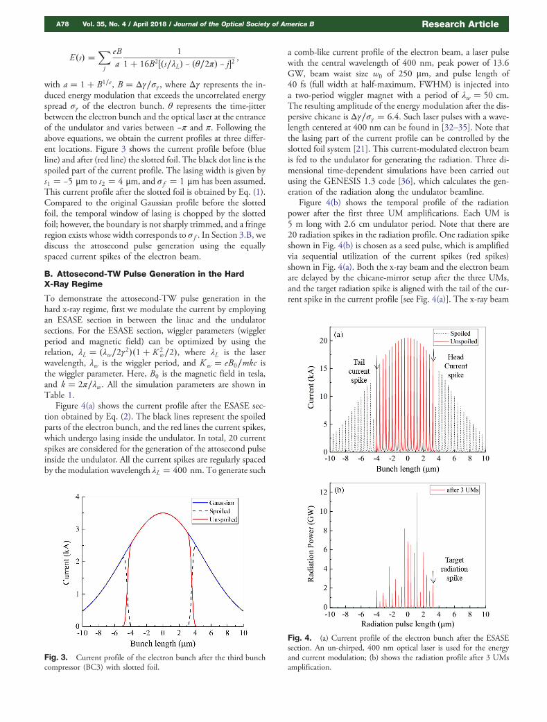
Figure 4(a) shows the current profile after the ESASE sec-tion obtained by Eq. (2). The black lines represent the spoiledparts of the electron bunch, and the red lines the current spikes,which undergo lasing inside the undulator. In total, 20 currentspikes are considered for the generation of the attosecond pulseinside the undulator. All the current spikes are regularly spacedby the modulation wavelength λL � 400 nm. To generate such
a comb-like current profile of the electron beam, a laser pulsewith the central wavelength of 400 nm, peak power of 13.6GW, beam waist size w0 of 250 μm, and pulse length of40 fs (full width at half-maximum, FWHM) is injected intoa two-period wiggler magnet with a period of λw � 50 cm.The resulting amplitude of the energy modulation after the dis-persive chicane is Δγ∕σγ � 6.4. Such laser pulses with a wave-length centered at 400 nm can be found in [32–35]. Note thatthe lasing part of the current profile can be controlled by theslotted foil system [21]. This current-modulated electron beamis fed to the undulator for generating the radiation. Three di-mensional time-dependent simulations have been carried outusing the GENESIS 1.3 code [36], which calculates the gen-eration of the radiation along the undulator beamline.
Figure 4(b) shows the temporal profile of the radiationpower after the first three UM amplifications. Each UM is5 m long with 2.6 cm undulator period. Note that there are20 radiation spikes in the radiation profile. One radiation spikeshown in Fig. 4(b) is chosen as a seed pulse, which is amplifiedvia sequential utilization of the current spikes (red spikes)shown in Fig. 4(a). Both the x-ray beam and the electron beamare delayed by the chicane-mirror setup after the three UMs,and the target radiation spike is aligned with the tail of the cur-rent spike in the current profile [see Fig. 4(a)]. The x-ray beam
Fig. 3. Current profile of the electron bunch after the third bunchcompressor (BC3) with slotted foil.
Fig. 4. (a) Current profile of the electron bunch after the ESASEsection. An un-chirped, 400 nm optical laser is used for the energyand current modulation; (b) shows the radiation profile after 3 UMsamplification.
A78 Vol. 35, No. 4 / April 2018 / Journal of the Optical Society of America B Research Article

delay system is composed of four dipole magnets and a set ofplane mirrors [see Fig. 1(c)]. Four dipole magnets (the magnetchicane, R56 ∼ 12.31 μm) delay the electron bunch and dilutethe microbunching developed in the three UMs during theSASE radiation, while the set of mirrors creates a time delayto the radiation beam relative to the electron beam. After align-ment with the tail current spike, the target radiation spike isamplified in the two UMs [Fig. 1(d)]. Now the electron beamis delayed by a relatively small magnet chicane (R56 ∼ 1 μm) toalign the target radiation spike with the current spike next tothe tail current spike and amplified for one UM only. Thisamplification stage is repeated seventeen times (17 UMs) inthe downstream undulator. The number of undulator modulesused in 20 amplification stages are set as 3, 2, 1, 1, 1, 1, 1, 1, 1,1, 1, 1, 1, 1, 1, 1, 1, 1, 1, 1, respectively.
Figure 5(a) shows the temporal profile of the radiation afterthe amplification in 23 UMs along the undulator, and Fig. 5(b)is the corresponding power spectrum. One can see that a fewneighboring radiation spikes are also amplified during the seed-ing. The pulse duration and power of the main radiation spikeare 32 attosecond FWHM and 4 TW, respectively, correspond-ing to 6.4 × 10¹⁰ photons per pulse. The pulse energy is 0.128millijoule (mJ). The amplification of the radiation is based onthe super-radiant behavior of short pulses [37,38], where thepower level can significantly exceed the saturation power of anXFEL, while its pulse length is shortened. Note that the current
enhancement due to the ESASE section leads to increase in theenergy spread of the electrons near the current spike, which canbe estimated by the following formula [15]: σγ�z�∕σγ0 � 1�aB�erf �4z∕�Δz0B1∕8� � π� −erf �4z∕�Δz0B1∕8� − π��, whereerf �x� is the error function, z is the coordinate along theelectron bunch, and Δz0 � λL∕2B is the width of the currentspike. Figure 6 shows the energy spread of the electron beamcorresponding to the current peak shown in the inset. Thisenergy spread is considered in the simulation of the radiationgeneration.
C. Effects of the Chirped Laser on the CurrentModulation and on the Attosecond Pulse Generation
To solve the problem of neighboring radiation pulses with non-negligible power [shown in Fig. 5(a)], the optical laser having achirped frequency is used for the modulation of energy andcurrent in the ESASE section. The chirped laser pulse createsan increasing variation in the spacing between the currentspikes. To get an arbitrary chirp rate, spatial light modulators[39,40] are used for the femtosecond pulse shaping [41,42]with a pulse energy of the order of mJ. Our simulation is firstrepeated for the same setup and for the same set of electronbeam, laser beam, and undulator parameters as shown inTable 1. Figure 7 shows the current profile with the increasing
Fig. 5. (a) Radiation pulse profile taken after 23 UMs amplification;(b) corresponding power spectrum.
Fig. 6. Normalized energy spread versus distance along the electronbunch (corresponding to the peak current shown in the inset).
Fig. 7. Unequally spaced current spikes of the electron bunch afterthe ESASE section when a chirped, 400 nm optical laser pulse is used.
Research Article Vol. 35, No. 4 / April 2018 / Journal of the Optical Society of America B A79

variation of the mutual spacing between the current spikes fromthe tail current spike towards the head current spike. The black-dotted spikes show the spoiled part of the electron bunch, andthe red spikes show the unspoiled part of the electron beamused for the generation of the radiation inside the undulator.In total, 10 current spikes are considered for the lasing insidethe undulator. Figure 8 shows the variation in the mutual spac-ing of the current spikes generated by the chirped laser pulse.
Figure 9(a) shows the radiation profile after 23 UMs SASEradiation. Here, for the normal SASE amplification, initially 2UMs are considered. The last pulse in the radiation profile ischosen as a target radiation pulse for seeding. This target pulseis delayed by a chicane-mirror setup similarly, as mentioned inSection 3.B. After the chicane-mirror setup, the target radiationpulse is seeded by the tail current spike and amplified through 2UMs. Note that only the target radiation pulse is amplified sig-nificantly due to the seeding with the current spike, while restof the radiation pulses are amplified just by normal SASEradiation. Now, the amplified target pulse is aligned with thecurrent spike next to the tail current spike using an electron-beam delay and is amplified through 2 UMs. For smallelectron-beam delays, small magnetic chicanes are used inthe drift section available in between the two UMs. Each time,the target radiation pulse aligns with the next current spike,using the fresh part of the electron beam. It implies that theenergy spread of the electron beam remains under controland the target pulse keeps amplified using all the remainingcurrent spikes one by one via electron-beam delays in severalstages. In this simulation, because of the smaller number ofcurrent spikes compared to the case of the equally spaced spikes(20 spikes), the simulation is carried out with two chicane-mirror stages to attain an attosecond-TW pulse. Here, thenumber of UMs used in 21 amplification stages are set as 2,2, 1, 1, 1, 1, 1, 1, 1, 1, 1, 1, 1, 1, 1, 1, 1, 1, 1, 1, 1, respectively.After 23 UMs, the simulation results show a single IAP with 42attosecond pulse duration, 3.5 TW power, and ∼1 × 10¹¹ pho-tons per pulse in the hard x-ray region. It is worth to mentionhere that the final pulse width of the IAP can be reducedfurther by optimization of the rate of chirp in the optical laser.Figure 9(b) shows very clean spectral profile. For the realizationof the x-ray delay unit, the optical components must meet
various demands, such as a high reflectivity, delay with sub-femtosecond (fs) to attosecond resolution, and a large delayrange over the wide photon energy spectrum of the XFEL(1–12 keV). These properties have to be achieved with aminimal disturbance to the beam position and direction anda high mechanical stability. Note that the small reflectivityat large incident angles demands a grazing incident geometry.The critical angle is typically in the range of 10 arcmins(1 arcmin � 1°∕60) to 2° for the energy range of 0.1 to10 keV for surfaces like Au, Ni, Pt, or Ir. The detailed designof the chicane-mirror system is given in [27]. Table 2 shows theparameter ranges of the optical and electron beam delays usedhere. For the robustness of the scheme, we tested the effects of
Fig. 8. The variation of the spacing between the current spikes usedto get isolated attosecond x-ray pulse.
Fig. 9. (a) Isolated attosecond x-ray pulse at the end of the undu-lator obtained by using a chirped optical laser pulse in the ESASE sec-tion. In total, 23 UMs are considered in the undulator for the radiationamplification. (b) Corresponding power spectrum.
Table 2. Optical and Electron-Beam Delay ParametersUsed in Our Simulation for Scheme [25]
Parameters Value
Chicane-mirror system:Momentum compaction factor (R56) ∼12.31 μmMirror length 5–6 cmMirror deflection angle (θ) 0.1°Reflectivity >90%Electron delay system:Momentum compaction factor(R56) 1–3 μm
A80 Vol. 35, No. 4 / April 2018 / Journal of the Optical Society of America B Research Article

the shot noise on the peak power of the x-ray pulse and thepulse duration. The simulation was performed for 10 differentinitial seeds for the random number generator used for particlephase fluctuation in GENESIS 1.3 code [36]. Figure 10 showsthe average power along the undulator for the case with thefrequency-chirped laser. The average power after the amplifica-tion through 23 UM stages is 3.0� 1 TW (red curve), whilethe average pulse duration is 65� 23 attoseconds at FWHM.
Now, we exclude the slotted foil and x-ray delay unit asshown in [28,29] and consider the frequency-chirped opticallaser in the ESASE section. First, we consider the same currentprofile as shown in Fig. 7. The whole current profile is fed tothe undulator for lasing. For each amplification stage, a similarnumber of UMs as in the previous method is used for radiationpulse amplification. One target radiation spike is chosen afterthe first stage undulator, which acts as a seed for a number offresh current spikes using electron beam delays by magnetchicane and amplified through the undulator. Figure 11 showsthree different simulations of final x-ray pulse obtained forthree different frequency chirps used in the optical laser, andthe inset of Fig. 11 shows the corresponding variation of thecurrent spikes’mutual spacing. For the first case (black curve),13 UMs are used for target pulse amplification to get 3 TW inpower and 50 attosecond FWHM in pulse duration. For thesecond case (red curve), 19 UMs are used to get 3.9 TW inpower and 96 attosecond FWHM in pulse duration, while forthe third case (blue line), 20 UMs are used to get 3.47 TW inpower and 100 attosecond FWHM in pulse duration. Hence,one can notice from Fig. 11 that frequency-chirp optimizationis crucial here. Only the first case (black curve) shows a pureIAP while in other two cases, (red curve and blue curve), onecan see that side peaks are amplified even for the frequency-chirped laser. In addition, this study shows that with preciseoptimization of the laser frequency chirp, the final radiationpulse width and the total undulator length can be shortened.
For experimental realization of these schemes, the ESASEoptical laser pulse should be synchronized properly with theelectron beam. The change in the RF phase of the linac willshake the arrival time of the electron beam at the entrance ofthe wiggler. However, time-jitter simulations in the PAL-XFELTDR report shows that a change of 0.05° in RF phases gives a
40 fs time jitter at the entrance of the undulator [43]. In thisstudy, we considered a 70 fs long electron bunch. The longelectron bunch minimizes the chance for the electron beamto be missed by the laser pulse during the interaction. The laserand electron beam can be properly synchronized in the experi-ment. Apart from that, synchronization at the user end stationis also crucial for scanning of the pump-probe delay with ahigh degree of precision. In this context, a few techniques haverecently been proposed and advanced [44–46].
4. CONCLUSION
The first lasing of the hard x-ray FEL line at PAL-XFEL wasachieved in 2016. It will eventually produce coherent hardx-ray pulses with gigawatt power and pulse durations as shortas 10 femtoseconds. As a future upgrade, we examined twoschemes recently proposed for attosecond-TW XFEL usingPAL-XFEL parameters. Our simulations show the generationof a 32 attosecond FWHM pulse duration with 4 TW in power(0.128 mJ pulse energy) at 12.4 keV photon energy using thePAL-XFEL parameters. However, this radiation pulse consistsof several side attosecond pulses along with the main target ra-diation pulse. To suppress the amplification of the side radia-tion pulses, the chirped optical laser pulse is introduced in theESASE section to create the current spikes with increasingseparation between the spikes. Finally, at the end of the undu-lator, a single IAP of 42 attosecond FWHM pulse duration,∼3.5 TW in power (0.147 mJ pulse energy), and ∼1 × 10¹¹photons per pulse is obtained. Towards a simpler layout, with-out slotted foil and optical delay units, an isolated-attosecondx-ray pulse of 3 TW in power and 50 attosecond FWHM pulseduration is generated via chirped current profile introducedthrough a frequency-chirped optical laser in the ESASE section.The output radiation pulse is perfectly synchronized with anoptical laser and readily used in pump-probe experimentsthat can capture ultra-fast electron dynamics in atoms, mole-cules, and solids. These schemes open up the future upgradepossibilities to enhance the capability of the PAL-XFEL interms of increased power and reduced pulse duration.
Fig. 10. Average radiation power (red line) and the radiation power(grey lines) versus undulator length for 10 different random seeds.
Fig. 11. Isolated attosecond pulse generation in the hard x-rayundulator for different laser frequency chirps. Inset shows the mutualspacing between the current spikes versus number for each currentspike.
Research Article Vol. 35, No. 4 / April 2018 / Journal of the Optical Society of America B A81

Funding. National Research Foundation of Korea (NRF);Ministry of Science, ICT and Future Planning (MSIP) (NRF-2016R1A5A1013277) and PAL-XFEL project, Korea.
REFERENCES
1. F. Krausz and M. Ivanov, “Attosecond physics,” Rev. Mod. Phys. 81,163–234 (2009).
2. P. B. Corkum and F. Krausz, “Attosecond science,” Nat. Phys. 3,381–387 (2007).
3. G. Sansone, E. Benedetti, F. Calegari, C. Vozzi, L. Avaldi, R.Flammini, L. Poletto, P. Villoresi, C. Altucci, R. Velotta, S. Stagira,S. De Silvestri, and M. Nisoli, “Isolated single-cycle attosecondpulses,” Science 314, 443–446 (2006).
4. E. Goulielmakis, M. Schultze, M. Hofstetter, V. S. Yakovlev, J.Gagnon, M. Uiberacker, A. L. Aquila, E. M. Gullikson, D. T.Attwood, R. Kienberger, F. Krausz, and U. Kleineberg, “Single-cyclenonlinear optics,” Science 320, 1614–1617 (2008).
5. F. Ferrari, F. Calegari, M. Lucchini, C. Vozzi, S. Stagira, G. Sansone,and M. Nisoli, “High-energy isolated attosecond pulses generatedby above-saturation few-cycle fields,” Nat. Phys. 4, 875–879 (2010).
6. M. Altarelli, R. Brinkmann, M. Chergui, W. Decking, B. Dobson, S.Düsterer, G. Grübel, W. Graeff, H. Graafsma, J. Hajdu, J.Marangos, J. Pflüger, H. Redlin, D. Riley, I. Robinson, J.Rossbach, A. Schwarz, K. Tiedtke, T. Tschentscher, I. Vartaniants,H. Wabnitz, H. Weise, R. Wichmann, K. Witte, A. Wolf, M. Wulff,and M. Yurkov, “The European X-ray free-electron laser,” Technicaldesign report, DESY Report 2006–097 (2006), pp. 1–630.
7. P. Emma, R. Akre, J. Arthur, R. Bionta, C. Bostedt, J. Bozek,A. Brachmann, P. Bucksbaum, R. Coffee, F.-J. Decker, Y. Ding,D. Dowell, S. Edstrom, A. Fisher, J. Frisch, S. Gilevich, J. Hastings,G. Hays, P. Hering, Z. Huang, R. Iverson, H. Loos, M.Messerschmidt, A. Miahnahri, S. Moeller, H.-D. Nuhn, G. Pile,D. Ratner, J. Rzepiela, D. Schultz, T. Smith, P. Stefan, H.Tompkins, J. Turner, J. Welch, W. White, J. Wu, G. Yocky, and J.Galayda, “First lasing and operation of an ångstrom-wavelengthfree-electron laser,” Nat. Photonics 4, 641–647 (2010).
8. T. Ishikawa, H. Aoyagi, T. Asaka, Y. Asano, N. Azumi, T. Bizen, H.Ego, K. Fukami, T. Fukui, Y. Furukawa, S. Goto, H. Hanaki, T.Hara, T. Hasegawa, T. Hatsui, A. Higashiya, T. Hirono, N. Hosoda,M. Ishii, T. Inagaki, Y. Inubushi, T. Itoga, Y. Joti, M. Kago, T.Kameshima, H. Kimura, Y. Kirihara, A. Kiyomichi, T. Kobayashi, C.Kondo, T. Kudo, H. Maesaka, X. M. Maréchal, T. Masuda, S.Matsubara, T. Matsumoto, T. Matsushita, S. Matsui, M. Nagasono,N. Nariyama, H. Ohashi, T. Ohata, T. Ohshima, S. Ono, Y. Otake,C. Saji, T. Sakurai, T. Sato, K. Sawada, T. Seike, K. Shirasawa,T. S. Moto, S. Suzuki, S. Takahashi, H. Takebe, K. Takeshita, K.Tamasaku, H. Tanaka, R. Tanaka, T. Tanaka, T. Togashi, K.Togawa, A. Tokuhisa, H. Tomizawa, K. Tono, S. Wu, M. Yabashi,M. Yamaga, A. Yamashita, K. Yanagida, C. Zhang, T. Shintake, H.Kitamura, and N. Kumagai, “A compact X-ray free-electron laser emit-ting in the sub-ångström region,” Nat. Photonics 6, 540–544 (2012).
9. J. Amann, W. Berg, V. Blank, F.-J. Decker, Y. Ding, P. Emma, Y.Feng, J. Frisch, D. Fritz, J. Hastings, Z. Huang, J. Krzywinski, R.Lindberg, H. Loos, A. Lutman, H.-D. Nuhn, D. Ratner, J. Rzepiela,D. Shu, Y. Shvyd’ko, S. Spampinati, S. Stoupin, S. Terentyev, E.Trakhtenberg, D. Walz, J. Welch, J. Wu, A. Zholents, and D. Zhu,“Demonstration of self-seeding in a hard-X-ray free-electron laser,”Nat. Photonics 6, 693–698 (2012).
10. S. Ko, H. S. Kang, H. Heo, C. Kim, G. Kim, C.-Ki Min, H. Yang, S. Y.Baek, H. J. Choi, G. Mun, B. R. Park, Y. J. Suh, D. C. Shin, J. Hu, J.Hong, S. Jung, S. H. Kim, K. H. Kim, D. Na, S. S. Park, Y. J. Park,Y. G. Jung, S. H. Jeong, H. G. Lee, S. Lee, S. Lee, B. Oh, H. S. Suh,J. H. Han, M. H. Kim, N. S. Jung, Y. C. Kim, M. S. Lee, B. H. Lee, C. W.Sung, I. S. Mok, J. M. Yang, Y. W. Parc, W. W. Lee, C. S. Lee, H. Shin,J. H. Kim, Y. Kim, J. H. Lee, S. Y. Park, J. Kim, J. Park, I. Eom, S. Rah,S. Kim, K. H. Nam, J. Park, J. Park, S. Kim, S. Kwon, R. An, S. H. Park,K. S. Kim, H. Hyun, S. N. Kim, S. Kim, C. J. Yu, B. S. Kim, T. H. Kang,K. W. Kim, S. H. Kim, H. S. Lee, H. S. Lee, K. H. Park, T. Y. Koo, D. E.
Kim, and K. B. Lee, “Construction and commissioning of PAL-XFELfacility,” Appl. Sci. 7, 479 (2017).
11. J. Lee, C. H. Shim, M. Yoon, I. Hwang, Y. W. Parc, and J. Wu,“Optimization of the hard X-ray self-seeding layout of the PAL-XFEL,”Nucl. Instrum. Methods Phys. Res. A 798, 162–166 (2015).
12. A. A. Zholents and W. M. Fawley, “Proposal for intense attosecond radi-ation fromanX-ray free-electron laser,”Phys. Rev. Lett. 92, 224801 (2004).
13. P. Emma, K. Bane, M. Cornacchia, Z. Huang, H. Schlarb, G.Stupakov, and D. Walz, “Femtosecond and subfemtosecond x-raypulses from a self-amplified spontaneous-emission-based free-electron laser,” Phys. Rev. Lett. 92, 074801 (2004).
14. E. L. Saldin, E. A. Schneidmiller, and M. V. Yurkov, “A new techniqueto generate 100 GW-level attosecond X-ray pulses from the X-raySASE FELs,” Opt. Commun. 239, 161–172 (2004).
15. A. A. Zholents, “Method of an enhanced self-amplified spontaneousemission for x-ray free electron lasers,” Phys. Rev. Spec. Top Accel.Beams 8, 040701 (2005).
16. A. A. Zholents and G. Penn, “Obtaining attosecond x-ray pulses usinga self-amplified spontaneous emission free electron laser,” Phys. Rev.Spec. Top Accel. Beams 8, 050704 (2005).
17. E. L. Saldin, E. A. Schneidmiller, and M. V. Yurkov, “Self-amplifiedspontaneous emission FEL with energy-chirped electron beam andits application for generation of attosecond x-ray pulses,” Phys.Rev. Spec. Top Accel. Beams 9, 050702 (2006).
18. D. Xiang, Z. Huang, and G. Stupakov, “Generation of intense attosec-ond x-ray pulses using ultraviolet laser inducedmicrobunching in elec-tron beams,” Phys. Rev. Spect. Top Accel. Beams 12, 060701 (2009).
19. Y. Ding, Z. Huang, D. Ratner, P. Bucksbaum, and H. Merdji,“Generation of attosecond x-ray pulses with a multicycle two-color en-hanced self-amplified spontaneous emission scheme,” Phys. Rev.Spec. Top Accel. Beams 12, 060703 (2009).
20. Y. Ding, A. Brachmann, F.-J. Decker, D. Dowell, P. Emma, J. Frisch,S. Gilevich, G. Hays, Ph. Hering, Z. Huang, R. Iverson, H. Loos, A.Miahnahri, H.-D. Nuhn, D. Ratner, J. Turner, J. Welch, W. White, andJ. Wu, “Measurements and simulations of ultralow emittance and ul-trashort electron beams in the linac coherent light source,” Phys. Rev.Lett. 102, 254801 (2009).
21. Y. Ding, F.-J. Decker, P. Emma, C. Feng, C. Field, J. Frisch, Z. Huang,J. Krzywinski, H. Loos, J. Welch, J. Wu, and F. Zhou, “FemtosecondX-ray pulse characterization in free-electron lasers using a cross-correlation technique,” Phys. Rev. Lett. 109, 254802 (2012).
22. N. R. Thompson and B. W. J. McNeil, “Mode locking in a free-electronlaser amplifier,” Phys. Rev. Lett. 100, 203901 (2008).
23. D. J. Dunning, B.W. J. McNeil, and N. R. Thompson, “Few-cycle pulsegeneration in an X-ray free-electron laser,” Phys. Rev. Lett. 110,104801 (2013).
24. S. Kumar, M. S. Hur, and M. Chung, “Analyzing the effect of slotted foilon radiation pulse profile in a mode locked afterburner X-ray freeelectron laser,” J. Appl. Phys. 121, 243101 (2017).
25. T. Tanaka, “Proposal for a pulse-compression scheme in X-ray free-electron lasers to generate a multiterawatt, attosecond X-ray pulse,”Phys. Rev. Lett. 110, 084801 (2013).
26. E. Prat and S. Reiche, “Simple method to generate terawatt-attosecond X-ray free-electron-laser pulses,” Phys. Rev. Lett. 114,244801 (2015).
27. S. Kumar, Y. W. Parc, A. S. Landsman, and D. E. Kim, “Temporally-coherent terawatt attosecond XFEL synchronized with a few cyclelaser,” Sci. Rep. 6, 37700 (2016).
28. T. Tanaka, Y. W. Parc, Y. Kida, R. Kinjo, C. H. Shim, I. S. Ko, B. Kim,D. E. Kim, and E. Prate, “Using irregularly spaced current peaks togenerate an isolated attosecond X-ray pulse in free-electron lasers,”J. Synchrotron Radiat. 23, 1273–1281 (2016).
29. Z. Wang, C. Feng, and Z. Zhao, “Generating isolated terawatt-attosecond x-ray pulses via a chirped-laser-enhanced high-gain free-electron laser,”Phys.Rev.Spec. TopAccel. Beams20, 040701 (2017).
30. P. Maine, D. Strickland, P. Bado, M. Pessot, and G. Mourou,“Generation of ultrahigh peak power pulses by chirped pulse amplifi-cation,” IEEE J. Quantum Electron. 24, 398–403 (1988).
31. G. Geloni, V. Kocharyan, and E. Saldin, “Scheme for femtosecond-resolution pump-probe experiments at XFELs with two-color tenGW-level X-ray pulses,” DESY Report No. 10–004.
A82 Vol. 35, No. 4 / April 2018 / Journal of the Optical Society of America B Research Article

32. T. Kanai, X. Zhou, T. Liu, A. Kosuge, T. Sekikawa, and S. Watanabe,“Generation of terawatt 10-fs blue pulses by compensation for pulse-front distortion in broadband frequency doubling,” Opt. Lett. 29, 2929–2931 (2004).
33. E. L. F. Filho, C.-J. Lai, K.-H. Hong, V. M. Gkortsas, S. W. Huang, L. J.Chen, and F. X. Kärtner, “Scaling of high-order harmonic efficiencieswith visible wavelength drives: A route to efficient extreme ultravioletsources,” Appl. Phys. Lett. 97, 061107 (2010).
34. O. Gobert, G. Mennerat, R. Maksimenka, N. Fedorov, M. Perdrix, D.Guillaumet, C. Ramond, J. Habib, C. Prigent, D. Vernhet, T.Oksenhendler, and M. Comte, “Efficient broadband 400 nm noncol-linear second-harmonic generation of chirped femtosecond laserpulses in BBO and LBO,” Appl. Opt. 53, 2646–2655 (2014).
35. C. Marceau, T. J. Hammond, A. Naumov, P. B. Corkum, and D. M.Villeneuve, “Wavelength scaling of high harmonic generation for267 nm, 400 nm and 800 nm driving laser,” J. Phys. Commun. 1,015009 (2017).
36. S. Reiche, “GENESIS 1.3: a fully 3D time-dependent FEL simulationcode,” Nucl. Instrum. Methods Phys. Res. A 429, 243–248 (1999).
37. R. Bonifacio, L. De Salvo, P. Pierini, and N. Piovella, “The superra-diant regime of a FEL: analytical and numerical results,” Nucl.Instrum. Methods Phys. Res. A 296, 358–367 (1990).
38. R. Bonifacio, N. Piovella, and B. W. J. McNeil, “Superradiant evolutionof radiation pulses in a free-electron laser,” Phys. Rev. A 44,R3441–R3444 (1991).
39. A. M. Weiner, “Femtosecond pulse shaping using spatial light modu-lators,” Rev. Sci. Instrum. 71, 1929–1960 (2000).
40. J. W. Wilson, P. Schlup, and R. A. Bartels, “Ultrafast phase and am-plitude pulse shaping with a single, one dimensional, high-resolutionphase mask,” Opt. Express 15, 8979–8987 (2007).
41. T. Tanigawa, Y. Sakakibara, S. Fang, T. Sekikawa, and M.Yamashita, “Spatial light modulator of 648 pixels with liquid crystaltransparent from ultraviolet to near-infrared and its chirp compensa-tion application,” Opt. Lett. 34, 1696–1698 (2009).
42. H. Wang, Y. Wu, C. Li, H. Mashiko, S. Gilbertson, and Z. Chang,“Generation of 0.5 mJ, few cycle laser pulses by an adaptive phasemodulator,” Opt. Express 16, 14448–14455 (2008).
43. “PAL-XFEL Technical Design Report (TDR),” http://pal.postech.ac.kr/.44. M. Chini, H. I. Mashiko, H. Wang, S. Chen, C. Yun, S. Scott, S.
Gilbertson, and Z. Chang, “Delay control in attosecond pump-probeexperiments,” Opt. Express 17, 21459–21464 (2009).
45. S. Schulz, I. Grguras, C. Behrens, H. Bromberger, J. T. Costello, M. K.Czwalinna, M. Felber, M. C. Hoffmann, M. Ilchen, H. Y. Liu, T. Mazza,M. Meyer, S. Pfeiffer, P. Prędki, S. Schefer, C. Schmidt, U. Wegner, H.Schlarb, and A. L. Cavalieri, “Femtosecond all-optical synchronizationof an X-ray free-electron laser,” Nat. Commun. 6, 5938 (2015).
46. P. Cinquegrana, S. Cleva, A. Demidovich, G. Gaio, R. Ivanov, G. Kurdi,I. Nikolov, P. Sigalotti, and M. B. Danailov, “Optical beam transport to aremote location for low jitter pump-probe experiments with a free elec-tron laser,” Phys. Rev. Spec. Top Accel. Beams 17, 040702 (2014).
Research Article Vol. 35, No. 4 / April 2018 / Journal of the Optical Society of America B A83