
Generating User Interfaces for Pen-based Computers - … · Generating User Interfaces for...
12
Generating User Interfaces for Pen-based Computers Sitt Sen Chok and Kim Marriott Department of Computer Science and Software Engineering Monash University, Victoria, Australia {css,marr iott }@csse.monash.edu.au Abstract We provide an overview of the Penguins project. The aim of this project is to develop tools that facilitate the development of software for pen-based graphics edi- tors. Th e project is based on the intelligent pen and pa- per metaphor for human-computer interaction. In this metaphor, the user communicates with the computer using an application specific visual language composed of handwritten text and diagrams. As the diagram is drawn with a pen, the underlying graphic editor parses the diagram, performing error correction and collecting geometric constraints which capture the relationships between diagram components. During manipulation these constraints are maintained by the editor in order to preserve the semantics of the diagram. The Penguins system contains tools which, given a grammatical spec- ification of a visual language, automatically construct a core user interface for that visual language which em- bodies the intelligent pen and paper metaphor. This core user interface consists of a tokenizer, constraint so lver, layout co ntroller and constraint-based graph- ics editor together with an incremental parser for the specified visual language. The specification language is based on constraint multiset grammars. Introd uct ion Interactive graphic tablets and pen-based notepad com- puters are now on the market place. This new tech- nology, however, while offering great potential has not yet been very successful, mainly because software for pen-based computers is still immature. The aim of the Penguins project is to develop tools that facilitate the development of software for pen-based computers which takes full advantage of the pen's new capabilities. The project is based on the intelligent pen and paper metaphor for human-computer interaction with pen- based computers. In this interaction metaphor, the user communicates with the computer using an application specific visual language composed of handwritten text and diagrams. Input can be given in free form, mode- lessly in any order and place, and modified using natural gesture commands. Users are thus able to express them- selves directly in the visual lingua franca of their appli- cati on domain , such as statecharts, structural-chemical formulae, or mathemat ical equations. As the user draws - 67- the diagram, the underlying software recognizes the structure of the diagram, performing error correction and adding constr ai nts between th e diagram compo- nents . These constraints preserve the diagram seman- tics during direct manipulation. The Penguins system contains tools which, given a grammatical specification of a visual language, auto- mati cally construct a core user interface for that visual language which embodies the intelligent pen and pa- per m etap hor . The core user interface supports the creation , manipulation and interpretation of diagrams in the specified visual language . The specification lan- guage is based on constraint multiset grammars. The core user interface provides a constraint-based graphics editor that supports graphics primitives, such as lines, circles, texts and arrows. In order to provide support for free-hand gestures from a pen, a tokenizer is also provided: This maps input ge:;tures to the appropr ia te graphics primitives. A constraint solver is incorporated into the core user inte rface to provide the constraint solving mech anisms necessary for geometric error cor- rection and di agram manipulation. Certain modules in the generated program can be extended to cater for ap- plication specific computation. The core user interface, together with the application specific routines is com- piled to give the final pen-based application. In the future a layout controller will also be generated from the grammar. Figure 1 shows the main components of the Pengu ins system. There are three underlying ideas on which the Pen- guins system is bas ed - constraint multi set grammars, the metric space model and declarative grap h or dia- gram layout. There is a syn ergy between these ideas with each model formalizing a different part of the in- terface - recognition, manipulation and layout. How- ever, as each model uses geometric co nstraint s to rep- resent the semantics of the diagram, they fit naturall y together . The Penguins proje ct is still work in progress. Cur- rently, we have implemented the co nstraint solver, to- kenizer, graphi cs editor and the parser generator. We have demonstrated their use in the development of sev- eral visual user-interfaces, for instance , mathematical equations and state transition diagrams . These exam- From AAAI Technical Report FS-98-04. Compilation copyright © 1998, AAAI. (www.aaai.org). All rights reserved.
Transcript of Generating User Interfaces for Pen-based Computers - … · Generating User Interfaces for...

Generating User Interfaces for Pen-based Computers
Sitt Sen Chok and Kim Marriott
Department of Computer Science and Software Engineering Monash University, Victoria, Australia
{css,marriott }@csse.monash.edu.au
Abstract
We provide an overview of the Penguins project. The aim of this project is to develop tools that facilitate the development of software for pen-based graphics editors. The project is based on the intelligent pen and paper metaphor for human-computer interaction. In this metaphor, the user communicates with the computer using an application specific visual language composed of handwritten text and diagrams. As the diagram is drawn with a pen , the underlying graphic editor parses the diagram, performing error correction and collect ing geometric constraints which capture the relationships between diagram components. During manipulation these constraints are maintained by the editor in order to preserve the semantics of the diagram. The Penguins system contains tools which, given a grammatical specification of a visual language, automatically construct a core user interface for that visual language which embodies the intelligent pen and paper metaphor. This core user interface consists of a tokenizer, constraint so lver , layout controller and constraint-based graphics editor together with an incremental parser for the specified visual language. The specification language is based on constraint multiset grammars.
Introd uct ion Interactive graphic tablets and pen-based notepad computers are now on the market place. This new technology, however, while offering great potential has not yet been very successful , mainly because software for pen-based computers is still immature. The aim of the Penguins project is to develop tools that facilitate the development of software for pen-based computers which takes full advantage of the pen's new capabilities.
The project is based on the intelligent pen and paper metaphor for human-computer interaction with penbased computers. In this interaction metaphor, the user communicates with the computer using an application specific visual language composed of handwritten text and diagrams. Input can be given in free form, modelessly in any order and place, and modified using natural gesture commands. Users are thus able to express themselves directly in the visual lingua franca of their application domain , such as statecharts, structural-chemical formulae, or mathematical equations. As the user draws
- 67-
the diagram, the underlying software recognizes the structure of the diagram, performing error correction and adding constraints between the diagram components . These constraints preserve the diagram semantics during direct manipulation.
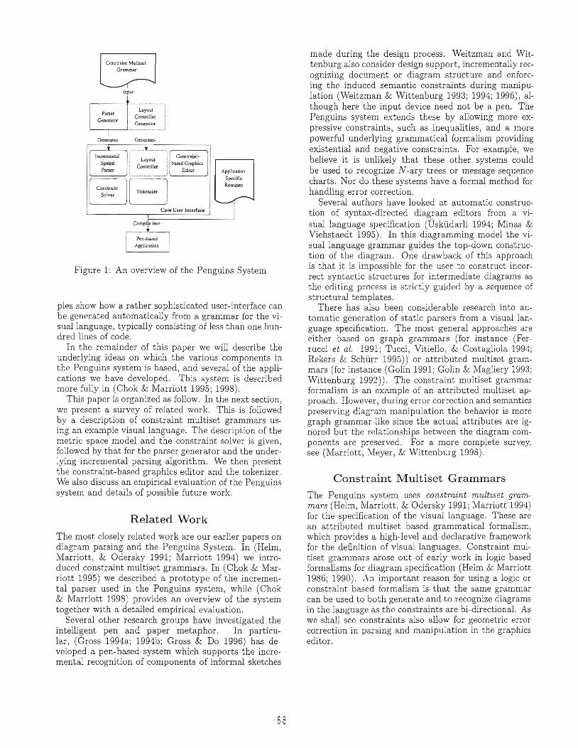
The Penguins system contains tools which, given a grammatical specification of a visual language, automatically construct a core user interface for that visual language which embodies the intelligent pen and paper metaphor . The core user interface supports the creation, manipulation and interpretation of diagrams in the specified visual language. The specification language is based on constraint multiset grammars. The core user interface provides a constraint-based graphics editor that supports graphics primitives, such as lines, circles, texts and arrows. In order to provide support for free-hand gestures from a pen, a tokenizer is also provided: This maps input ge:;tures to the appropriate graphics primitives. A constraint solver is incorporated into the core user interface to provide the constraint solving mechanisms necessary for geometric error correction and diagram manipulation. Certain modules in the generated program can be extended to cater for application specific computation. The core user interface, together with the application specific routines is compiled to give the final pen-based application. In the future a layout controller will also be generated from the grammar. Figure 1 shows the main components of the Penguins system.
There are three underlying ideas on which the Penguins system is based - constraint multi set grammars, the metric space model and declarative graph or diagram layout. There is a synergy between these ideas with each model formalizing a different part of the interface - recognition, manipulation and layout. However, as each model uses geometric constraints to represent the semantics of the diagram, they fit naturally together .
The Penguins project is still work in progress. Currently, we have implemented the constraint solver , tokenizer, graphics editor and the parser generator. We have demonstrated their use in the development of several visual user-interfaces , for instance, mathematical equations and state transition diagrams. These exam-
From AAAI Technical Report FS-98-04. Compilation copyright © 1998, AAAI. (www.aaai.org). All rights reserved.
ConsU'uin[ Multise[ GrammlU"
input
ConslIatnl
based Groprucs Edilor
Core User Interl9~
Application Specific Routines
Figure 1: An overview of the Penguins System
pies show how a rather sophisticated user-interface can be generated automatically from a grammar for the visuallanguage, typically consisting of less than one hundred lines of code.
In the remainder of this paper we will describe the underlying ideas on which the various components in the Penguins system is based, and several of the applications we have developed. This system is described more fully in (Chok & Marriott 1995; 1998).
This paper is organized as follow . In the next section, we present a survey of related work. This is followed by a description of constraint multiset grammars using an example visual language. The description of the metric space model and the constraint solver is given, followed by that for the parser generator and the underlying incremental parsing algorithm. We then present the constraint-based graphics editor and the tokenizer. We also discuss an empirical evaluation of the Penguins system and details of possible future work.
Related Work
The most closely related work are our earlier papers on diagram parsing and the Penguins System. In (Helm, Marriott, & Odersky 1991 ; Marriott 1994) we introduced constraint multiset grammars. In (Chok & Marriott 1995) we described a prototype of the incremental parser used in the Penguins system, while (Chok & Marriott 1998) provides an overview of the system together with a detailed empirical evaluation.
Several other research groups have investigated the intelligent pen and paper metaphor. In particular, (Gross 1994a; 1994b; Gross & Do 1996) has developed a pen-based system which. supports the incremental recognition of components of informal sketches
68
made during the design process. Weitzman and Wittenburg also consider design support, incrementally recognizing document or diagram structure and enforcing the induced semantic constraints during manipulation (Weitzman & Wittenburg 1993; 1994; 1996), although here the input device need not be a pen. The Penguins system extends these by allowing more expressive constraints, such as inequalities, and a more powerful underlying grammatical formalism providing existential and negative constraints. For example, we believe it is unlikely that these other systems could be used to recognize N -ary trees or message sequence charts. Nor do these systems have a formal method for handling error correction.
Several authors have looked at automatic construction of syntax-directed diagram editors from a visual language specification (Uskudarli 1994; Minas & Viehstaedt 1995). In this diagramming model the visual language grammar guides the top-down construction of the diagram. One drawback of this approach is that it is impossible for the user to construct incorrect syntactic structures for intermediate diagrams as the editing process is strictly guided by a sequence of structural templates.
There has also been considerable research into automatic generation of static parsers from a visual language specification. The most general approaches are either based on graph grammars (for instance (Ferrucci et al. 1991; Tucci, Vitiello, & Costagliola 1994; Rekers & Schurr 1995)) or attributed multiset grammars (for instance (Galin 1991; Galin & Magliery 1993; Wittenburg 1992)). The constraint multiset grammar formalism is an example of an attributed multiset approach. However, during error correction and semantics preserving diagram manipulation the behavior is more graph grammar-like since the actual attributes are ignored but the relationships between the diagram components are preserved. For a more complete survey, see (Marriott, YIeyer , & Wittenburg 1998).
Constraint Multiset Grammars
The Penguins system uses constraint multiset grammars (Helm, Marriott , & Odersky 1991; Ylarriott 1994) for the specification of the visual language. These are an attributed multi set based grammatical formalism, which provides a high-level and declarative framework for the definition of visual languages. Constraint multiset grammars arose out of early work in logic based formalisms for diagram specification (Helm & Marriott 1986; 1990) . An important reason for using a logic or constraint based formalism is that the same grammar can be used to both generate and to recognize diagrams in the language as the constraints are bi-directional. As we shall see constraints also allow for geometric error correction in parsing and manipulation in the graphics editor.

Productions in a constraint multiset grammar have the form
P ::= PI," " Pn where C
indicating that the non-terminal symbol P can be rewritten to the multiset of symbols Pt, ... , Pn whenever the attributes of all symbols satisfy the constraints C. The constraints enable information about spatial layout and relationships to be naturally encoded in the grammar. We will demonstrate this by mean of the grammar for state transition diagrams.
Productions in the grammar specify how states and transitions are composed from the terminal symbols which are circles, texts, lines and arrows. Every symbol in a constraint multiset grammar has a symbol type with associated attributes. Symbol types are either terminal or non- terminal. There is one distinguished nonterminal type called the start type. The declarations for each symbol type must be given in the grammar. Those for our example are as follows:
declare symboltype arc(start:point, mid:point,end:point, label:string):nonterminal;
declare symboltype startArc( start :point,mid :point, end:point) :nonterminal;
declare symboltype state( mid:point,radius:integer,label :string, kind:string):nonterminal;
declare symboltype transition( start:string,tran:string, end:string):nonterminal;
declare symboltype transitions( set:multiset<transition» :nonterminal;
declare symboltype states( set :multiset<state»:nonterminal;
declare symbol type std( ss:states,ts:transitions) :starttype;
For instance, the first declaration specifies that the symbol type arc is a non-terminal symbol and that it has four attributes: its start-point, its mid-point, its end-point and its label.
The simplest production in the grammar is that defining the arc. It specifies that an arc in a state transition diagram is composed of a text label T and an arrow A, and that the mid-points of T and A must be the same:
R:arc() ::= A:arrow,T:text where ( A.mid == T.mid
}
{ R.start = A.start; R.end = A.end; R.mid = A.mid; R.label = T. label;
69-
In many visual languages, there are language elements which are superficially similar but with quite different meanings. In the case of state transition diagrams, a start arc is very similar to an arc. The only difference between these two structures lies in the additional text label forming part of an arc structure. This poses potential ambiguity in parsing. For example, if an arrow is drawn, should it be recognized as a start arc or an arc? In static parsing such ambiguity is usually resolved by considering all possible maximal interpretations and then choosing the interpretation which explains all elements in the diagram. In our context such ambiguity is bad for at least two reasons. First, it makes parsing considerably more expensive since multiple parse trees must be constructed. Second, and even more importantly, it makes it extremely difficult to provide immediate feedback about what has been recognized so far during diagram construction since the ambiguity may only be resolvable once the complete diagram has been drawn. This problem can be overcome by the use of a negative constraint which specifies that a start arc is recognized if there is no text label R with the same mid-point as the arrow A. This essentially makes the grammar deterministic. The following is the defining production for startArc.
S:startArc() ::= A:arrow where ( not exist R:text where (R.mid == A.mid) { S.start A.start; S.end A.end; S.mid = A.mid;
}
A final state is made up of two circles Cl and C2 and text T satisfying three underlying geometric relationships. The first specifies that the mid-points of the circle Cl and the circle C2 are the same. Similarly, the second specifics equality of the mid-points of the circle Cl and the text T. The third ensures that C2 is the outermost circle. The following is the defining production for a final state.
S:state() ::= Cl:circle,C2:circ!e,T:text where (Cl.mid == C2 .mid &&
}
Cl.mid == T.mid && Cl.radius <= C2.radius { S.mid = Cl.mid; S.radius = C2.radius; S.label = T.label; S.kind = "final";
A start state is composed of a labelled circle, C and T, with a start arc A pointing to it. To avoid ambiguity in reductions involving the production for a start state and the production for a final state, a negative constraint is required. This negative constraint specifies that there must not be another circle M with the same mid-point, since if such a circle exists, then a final state should be recognized instead. The following shows the defining production for a start state.

S:state() :: = C:circle,I :text,A:startArc where (I.mid == C.mid && OnCircle(A.end,C.mid,C.radius) &&
}
not exist M:circle where (M.mid == C.mid) { S.mid = C.mid; S.radius = C.radius; S.label = I . label; S.kind = "start";
A normal state is similar to a start state, except that it does not have a start arc pointing to it. Again , there is a potential ambiguity in reductions. The problem is that a labelled circle that is rightfully part of a start state, may be recognized as a normal state instead. To remove such ambiguity, an explicit negative constraint is put in place, specifying that there must not be a start arc pointing to the labelled circle. Another possible ambiguity is between a normal state and a final state, similar to that between a start state and a final state. This ambiguity can be removed with an explicit negative constraint, specifying that there must not be another circle with the same mid-point .
S:state() ::= C:circle,I:text where not exist M:circle where (
M.mid == C.mid) &&
}
not exist A:startArc where ( OnCircle(A . end,C.mid,C.radius» &&
I.mid == C.mid { S .mid = C.mid; S . radius = C.radius; S.label = I . label; S. kind = "normal";
Apart from negative constraints. constramt multiset grammars also a llow existential qua'ntification. Expanding the constraint multiset grammar formalism in this way essentially makes it context-sensitive. It has been proven in Marriott et al (Nlarriott & Meyer 1997) that some sort of context-sensitivity is required for the specification of graph-based visual languages. The idea of existential quantification of variables is to allow the quantified variables to refer to symbols which have already been reduced as well as to symbols in the current sentence. Consider the following production which specifies a transition in a state transition diagram. The variables S1 and S2 are existentially quantified. This means that they can be assigned symbols from either the current sentence or from the previously reduced symbols.
I:transition() : .= A:arc where (
}
exist S1:state,S2 : state where ( OnCircle(A .start,S1.mid,S1.radius) && OnCircle(A.end,S2.mid,S2.radius»
{ I.start = S1.label; I . tran = A.label; I.end = S2 . label;
- 70 -
+ (a) Before applying the
production
I --- ---
I (b) After applying the
production
Figure 2: Applying the restricted production
In many graph-like visual languages it is useful to be able to collect symbols of the same type into a multiset or set. For instance, in the case of state transition diagrams, we wish to collect all of the states and all of the transitions. Collection productions support this activity. Thus the following productions collect all of the states and transitions in the diagram respectively.
SS:states() : :=* all S:state where (true) {
SS . set.Add(S);
IS:transitionsO : :=* all I : transition where (true)
IS.set.Add(T) ;
The final production in the grammar is the defining production for std. It specifies that a state transition diagram is composes of states SS and transitions IS
F:std() :: = SS:states,TS:transitions where (true) {
F . ss SS; F . ts = TS;
}
Constraint multiset grammars are more powerful than the example of state transition diagram suggests. Productions may also be unrestricted, that is more than one symbol may occur in the left-hand-side of a production rule. This allows, for instance, two crossed lines to be recognized as four non-crossing lines. This production is visually illustrated in Figure 2. However, the grammar writer must be careful with the use of such productions as they may lead to slow parsing and even non-termination.
L1 : line( ), L2:line(),L3:line(),L4:line () LA:line,LB:line where (
{ Intersect (LA,LB»
Ll.start = LA. start; L1.end = Intersection(LA,LB); L2.start = Intersection(LA,LB); L2.end = LA.end; L3 .start = LB . start; L3.end = Intersection(LA,LB); L4.start = Intersection(LA,LB); L4.end = LB.end;

The Intersect constraint specifies that the lines LA and LB intersect. The computation function Intersection determines the exact intersection point of the two lines, used to compute the end-points of the four new lines.
Constraint Solver
The constraint solver is a revised version of the toolkit, QOCA (Borning et al. 1997; Helm et al. 1995; Ylarriott, Chok, & Finlay 1998). This is a C++ constraint solving toolkit which supports the metric space model over various classes of arithmetic constraints.
In the metric space model, at any time there is a set of constraints over some variables, a metric which gives the distance between two assignments to the variables, and a current solution which is an assignment to the variable that satisfies the constraints. The variables correspond to graphical attributes of the graphics objects in the diagram and the diagram on the graphics display is, therefore , just a visual representation of the current solution.
Interaction in the metric space model can occur in three ways. First, a constraint may be added to the current set of constraints in which case the new solution is the assignment which is closest to the old assignment and which satisfies the new constraint set. Second, a constraint may be deleted from the current set of constraints, in which case the current solution remains unchanged. Finally, the current solution may be manipulated by "suggesting" a value for several of the variables. The new solution is the assignment which is closest to the old assignment and to the requested variable values and which satisfies the constraint set. The constraint set remains unchanged.
The metric space model provides a good formal basis for incremental manipulation of diagrams in a visual language specified by a constraint multiset grammar. The current constraints are generated in the parsing process. They capture the semantics or meaning of the diagram, for example in an equation they capture that in a division formula the numerator is above the denominator. During manipulation of the diagram the constraints ensure that only valid (sub- )diagrams in the language are constructed.
The QOCA toolkit provides three main classes. An instance of the CFloat class, behaves like a float except that if its value is set, this is treated as advice to the constraint solver, not as a true assignment to the variable. Only the constraint solver can set the value of a CFloat. LinConstraints represent the equality or inequality constraints in the problem. They are expressions built on top of CFloats. Actually, neither CFloats nor LinConstraints are directly manipulated by the programmer. Instead, for efficiency and safeness, they are mani pulated by means of the reference-counted "handles," CFloatHandle and ConstraintHandle respectively which can be assigned and constructed in the obvious ways.
71
To the application programmer the CFloat appears to have a single floating point value, which they set using the method SuggestValue and then read after calling the constraint solver using GetValue . Internally, however, the desired and actual values are kept separately. It also has a stay weight and an edit weight which, respectively, indicate the importance of leaving the variable unchanged if it is not being edited and the importance of changing it to the desired value when the variable is being edited. Both weights are non-negative floats and are set when the CFloat is created and cannot be subsequently changed.
QOCA currently provides three different solvers. Here we use the constraint solver CassSolver . This uses an incremental version of the Simplex algorithm for constraint solving and for finding the closest solution to the suggested solution which satisfies the equations. Constraints can be added to the solver one at a time using AddConstraint. vVith each addition the solver checks that the new constraint is compatible with the current constraints. This method is used to add constraints which enforce the geometric relationships found in parsing. RemoveConstraint allows the removal of a constraint which is currently in the solver. This is used when an object is deleted by the user or when invalidation of a negative constraint causes parsing to be undone.
The solver provides four methods for direct manipulation. First the application programmer tells the solver which variables are to be edited using multiple calls to SetEdi tVar. :'-Jext BeginEdi t is called. This initializes internal data structures for fast "resolving" of the constraints. ;.:Jow during manipulation the application programmer repeatedly sets the desired values of the edit variables and then calls the solver function Resal ve which efficiently computes the new solution to the constraints which is as close as possible to the old solution and to the new desired values of the edit variables. Finally the application programmer calls EndEdi t to signal the end of direct manipulation.
The following (slightly modified) example taken from (Marriott, Chok, & Finlay 1998) gives some feel for QOCA's interface. Consider a diagram consisting of a point (xm, ym) and a line from (xl, yl) to (xu, yu) in which the point is constrained to lie at the midpoint of the line. The following program fragment creates the variables and constraints , adds them to the solver and calls Solve to compute the initial position. The constructor for CFloatHandles takes three arguments: the stay and edit weights together with an initial desired value. ::'Jote that both xm and ym have a stay weight of zero indicating that they are "dependent variables," although they of course have a non-zero edit weight (otherwise, editing would never change their value). Next the program chooses xm and ym to be the edit variables, and then repeatedly samples the mouse to find the desired values and calls Resolve to compute the new value until the user releases the mouse button, which finishes the edit cycle.

CFloatHandle xl(l,lOOO,45), xm(a,1000,0), xu(1,1000,60), yl(l,1000,45), ym(a,lOOO,a), yu(1,laOO,60);
ConstraintHandle xeon = (l*xl + l*xu - 2*xm 0), yeon = (l*yl + l*yu - 2*ym a);
CassSolver solv;
solv.AddConstraint(xeon); solv.AddConstraint(yeon); solv.SolveO; DrawLine(xl .GetValue(),yl.GetValue(),
xu.GetValue(),yu.GetValue());
solv.SetEditVar(xm); solv.SetEditVar(ym); solv.BeginEdit(); while (mouse.button.down) {
xm.SuggestValue(mouse.x); ym.SuggestValue(mouse.y); solv.ResolveO; DrawLine(xl .GetValue(),yl.GetValue(),
xu . GetValue(),yu.GetValue()); }
solv . EndEdit 0 ;
Parser Generator and Parser From the application programmer's point of view, the parser generator is a black box which reads in a deterministic constraint multiset grammar and generates a parser for the visual language of the grammar in the form of C++ code.
Before the generation of the parser, the parser generator checks that the input grammar is stratified, that is, there is no recursion through negative constraints. The problem is that a production may directly or indirectly create the symbol it depends on negatively, that is, there may be a cycle in the dependency graph which passes through a negative constraint. For example, the following production has such a cycle.
W:negDep() ::= T:text where ( not exist N:negDep where (
N.mid == T.mid)) { .. . }
If there is a cycle through a negative constraint in the dependency graph, subsequent reductions will produce new symbols which may invalidate an earlier reduction involving the negative constraint. This may lead to an infinite loop in which a symbol is repeatedly created then deleted. Instead attention is restricted to grammars that are stratified in the sense that a production should only be allowed to depend negatively on those symbol types which are strictly lower in the dependency graph.
Conceptually, in order to determine if a grammar is stratified , one constructs the grammar's dependency graph. In the dependency graph, each node is a symbol type. If the symbol type A depends on the symbol type B, either through existential quantification or through reduction, then there is a positive dependency between
- 72
Figure 3: Dependency graph
the node for A and the node for B represented by the arc A <-- B. Similarly, a "negative" dependency between two symbol types can also be represented by a connection in the dependency graph, except that the symbol "<--~" is used instead of the symbol "<--". Figure 3 shows the dependency graph for the state transition diagram grammar presented in the previous section. Note that for collection production, there is an implicit negative constraint associated with the type it collects , since a collection is invalidated once a new symbol of the type it contains is created. It is obvious from the example dependency graph that the grammar is stratified.
It also is important to ensure that a reduction sequence is finite in length, so as to ensure that parsing termina tes. To ensure this, the grammar must be cyclefree, in the sense that there are no infinite reductions in which a single symbol is repeatedly reduced. The parser generator always ensures that the restricted portion of the grammar is cycle-free before code generation. Though the condition of a cycle-free can be extended to unrestricted grammars, currently has not been implemented. Therefore it is the programmer's responsibility to ensure this. Examining the dependency graph for the state transition diagram grammar , indicates that there is no cycle that can cause non-termination.
The generator performs two major optimizations to ensure efficiency of the parser. Firstly, it determines an optimal sequence of production evaluation in the constraint multiset grammar during parsing. This is done by examining the dependency graph. The result is a sequence of evaluations which ensures that clusters of strongly dependent productions are evaluated independently and in the right sequence. Since the dependency graph only shows symbol types, all the defining productions for each symbol type are evaluated as a group. As an example, the following shows an optimal sequence evaluation based on the dependency graph given in Figure 3:

are, startArc, [state (normal ) , state (final), state(start)], transition, states, transitions, std.
Secondly, it minimizes the number of constraints created during parsing. This is done by ensuring that only constraints over attributes of terminal symbols are considered by the embedded constraint solver. Attributes of non-terminal symbols are only a reference to attributes of terminal symbols. Further optimization of this nature can be done by ensuring that non-constraint datatypes do not add constraints to the solver.
In an interactive diagramming environment, incrementality in parsing is crucial since efficiency is a prime factor in such an environment. The generated parser is incremental. Whenever a graphics object is input, the parser updates the parse tree with minimum computation . This is somewhat difficult because negative constraints mean that parsing is non-monotonic - adding a new object may make an earlier reduction invalid. To demonstrate this , consider the simple state transition diagram shown in Figure 4(a). This diagram is initially recognized as a start state, but an additional text label "a" nullifies this initial result. Instead , an arc and a normal state should be identified, as shown in Figure 4(b).
The incremental parser performs parsing in a bottomup fashion , by taking a multiset of terminal symbols and repeatedly using satisfiable production rules in the grammar to combine symbols into larger and larger parse trees.
During diagram creation whenever a new graphics object is drawn, two events occur. Firstly, the parser checks whether the newly added object invalidates any previously satisfiable negative constraints. If invalidation of negative constraints occurs, then relevant sections of the parse forest will be destroyed and in the process, makes available some symbols for use for the current incremental parse. Secondly, a parse is performed to update the parse forest based on this newly added object, and if any, the made available symbols.
For the purpose of efficient parsing, constraint checking performed in the evaluation of each production, is divided into two stages . The main idea is to minimize the number of constraint additions. This is especially true for the case of a production with multiple constraints, where one constraint is satisfiable does not always imply that the remaining constraints are also satisfiable. The two stages involved are the constraint checking stage and the constraint adding stage.
During the constraint checking stage , constraints in a production are considered satisfiable if the associated errors are within the accepted tolerance. For example, points A and B are considered equal if the distance between them is within the acceptable tolerance. If the constraint checking stage is successful, then the con-
- 73
stJ.[e!.ta.r\ I . i
(a) Initial recognition (b) Addition oftbe text label "a"
Figure 4: Parsing with negative constraints
,----_.-
0 .. o coosrraint
consb'Uction constraint
solving
.@ ....... : ... ,l ...... r--·ft· '\
.~~
. .....--- 2
( viM:!\ ~~
•
{j) Figure 5: Geometric error correction
3
4
straint adding stage is performed, In this stage, all the constraints representing the geometric relationships between the attributes of symbols are added into the constraint set.
Diagrams constructed with a stylus or with a traditional graphics editor almost always contain geometric errors such as lines not quite touching the objects they should touch, Therefore, some form of automatic geometric error correction mechanism is crucial, providing immediate feedback to the user about what has been recognized and removing any geometric error ,
The error correction mechanism utilizes geometric constraints collected during the constraint adding stage. These geometric constraints represent the geometric relationships between symbols in a diagram. The constraint solver is then activated to perform constraint solving over the new constraint set, The purpose of the constraint solving step is to give new values to the attributes of symbols that satisfy all the constraints in the new constraint set, By doing this, the geometric errors involved in a diagram are removed. After the relevant constraints have been solved, the diagram is simply re-displayed to reflect the new solution of all the attributes of symbols. Figure 5 gives an overview of the steps involved to deliver geometric error correction based in the production for a normal state.
It is often necessary for a grammar to utilize constraint functions that are not already defined. Addi-
tional constraint functions are written as C++ procedures which extend the Constraint class. Each constraint function must implement the constraint checking and the constraint adding stages.
Graphics Editor The graphics editor combines with the generated incremental parser and the constraint solver to give a user interface based on the specified visual language. The editor allows the user to add or delete symbols and to manipulate components of the diagram.
In general, diagram interactions can be classified into two categories. The first category consists of interactions that modify the semantics of a diagram. These types of interactions include addition, deletion and separation of sub-diagrams. For example, adding another circle to a normal state in a state transition diagram changes the initial interpretation to a final state. The second category consists of interactions that preserve the semantics of the original diagram. These types of interactions, which are also called diagram manipulation, include moving and resizing of sub-diagrams.
The addition of graphics object has been discussed in the preceding section. Obviously, deletion of symbols from a diagram also changes the semantics of the diagram since previously identified diagram structures that depend on the deleted symbols become invalid. Thus the parse forest must be updated. A naive solution to the problem is to perform a complete re-parse of the entire diagram to obtain the corresponding parse forest. This solution is simple, but very inefficient.
A better solution is to remove only the relevant parts of the parse forest, and then perform an incremental parse. The end result of the incremental parse is a parse forest that reflects the changes made to the diagram. This is related to how negative constraints are handled.
It is useful to be able to separate a section of the diagram that was previously identified as a valid diagram structure. For example, in a state transition diagram, the user may have drawn a final state with two concentric circles and later decided to change it to a normal state by moving away one of the circles . The algorithm for such a separation operation is similar to that for deletion. The only different is that the selected object is not removed from the parse forest.
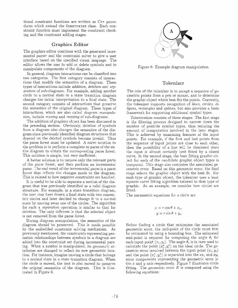
During diagram manipulation, the semantics of the diagram should be preserved. This is made possible by the embedded constraint solving mechanism. As previously mentioned, the constraints representing geometric relationships between symbols in a diagram are added into the constraint set during incremental parsing. When a symbol is manipulated, its geometric attributes are changed to reflect its new geometric location. For instance, imagine moving a circle that belongs to a normal state in a state transition diagram. When the circle is moved, the text is also moved to preserve the original semantics of the diagram. This is illustrated in Figure 6.
-7 4
Figure 6: Example diagram manipulation
Tokenizer
The role of the tokenizer is to accept a sequence of geometric points from a pen or mouse, and to determine the graphic object which best fits the points . Currently, the tokenizer supports recognition of lines, circles, ellipses, rectangles and splines, but also provides a basic framework for supporting additional symbol types.
Tokenization consists of three stages. The first stage is the filtering process designed to narrow down the number of possible symbol types, thus reducing the amount of computation involved in the later stages. This is achieved by examining features of the input points. For example, if the first and last points from the sequence of input points are close to each other, then the possibility of a line will be dismissed since the input is almost certainly best fitted by a closed curve. In the second stage, the best fitting graphic object for each of the candidate graphic object types is computed. This stage also computes the associated geometric error. Based on this geometric error, the final stage selects the graphic object with the best fit. For each type of graphic object, the tokenizer uses a least squares curve fitting algorithm tailored to that type of graphic. As an example, we consider how circles are fitted. The parametric equations for a circle are
x = rcose + X c,
Y = r sin e + Ye '
Before finding a circle that minimizes the associated geometric error , the mid-point of the circle must first be estimated by using a bounding box. The estimated mid-point is required for computing the angle ei for each input point (Xi, Yi ). The angle ei is in turn used to calculate the point (x:, y;) on the ideal circle. The geometric error involved between the input point (Xi, y;) and the point (xi, y;) is separated into the eXi and eYi error components representing the geometric error in the X and y axis respectively. Figure 7 illustrates circle fitting. The geometric error E is computed using the following equations:

E n-l n-l
= Lex?+ Ley; i=O i=O
Xi - x~ = Xi - (r cos ()i + Xc)
Yi - Y; = Yi - (r sin ()i + Yc)
where r and (xc, Yc) are the unknown radius and midpoint of the best fitting circle respectively. The angle ()i is simply tan- 1 ((Yi - Y~)/(Xi - x~)), where (x~, y~) is the estimated mid-point of the circle, and (Xi, Yi) is the ith input point. The radius r, and the mid-point (xc, Ye) which minimize E can therefore be found by solving the following partial differential equations:
oE or
n-l
-22)Xi - rcos()i - xc) = 0 i=O
n-l
= -21)Yi - r sin ()i - Yc) = 0 i =O
n-l
-2 L (Xi - r cos ()i - Xc) cos ()i i=O
n-l
-2 L(Yi - rsin()i - Yc) sin ()i = 0 i =O
In the actual circle fitting algonthms, these differential equations are rewritten in the form of matrices and are used for quickly finding (xc, Yc) and r of the best fitting circle.
Empirical Evaluation We have developed six applications, each employing a different visual language. The applications are:
• State transition diagrams: This takes a state transition diagram and determines if a string can be recognized by the corresponding finite state automata.
• Mathematical expressions: This recognizes a mathematical expression constructed from the standard trigonometric functions and arithmetic operators, and generates the corresponding Ib-TEX expression.
• Structured flow charts: This takes a structured flow chart consisting of if and loop constructs , and generates the corresponding Ib-TEX program pseudo code.
• Message sequence charts: This recognizes a message sequence charts which is commonly used to describe interaction between entities, how messages are interchanged between process instances, and what internal actions they performed.
• Binary tree: This recognizes a binary tree diagram representing a mathematical expression constructed from binary operators.
75
Ideal circle
......... ...... ....
Figure 7: Circle fitting
• N-ary tree: This recognizes trees with an arbitrary number of children. Although this visual language appears similar to that for binary trees, it is actually quite different, and relies on recursive use of negative constraints.
Diagrams for each of these applications are shown in Figure 8 (taken from (Chok & Marriott 1998)).
Static parsing of quite complex diagrams - actually those shown in Figure 8 - takes less than 30 milliseconds while incremental parsing of a new token takes a few milliseconds. As for parsing with error correction, there is a significant overhand due to the need for constraint solving. In all examples except the mathematical expressions, the performance is still good, taking less than one tenth of a second. The mathematical expression application is slow because of the large number of constraints involved. For a detailed empirical evaluation of the Penguins system, see to (Chok & Marriott 1998) .
Future Work The Penguins project is still work in progress and some aspects of the system are yet to be implemented. These include extending the constraint multiset grammar formalism include specification of layout requirements and layout control generator. From experience, it is often not desirable to specify layout requirements as required constraints in parsing since doing this imposes drastic restrictions a user can draw the diagram. Therefore layout requirements need to be specified separately from those for recognition. They can be viewed as additional geometric constraints which are considered by the constraint solver but not the incremental parser. As an example, consider a simple layout rule which specifies that a labelled circle must be ten pixel units in length.
L:labelledCircle() T.mid == C.mid {
C:circle,T:text where (
L. mid = C. mid ; L.radius = C.radius; L.label = T.text;
} layout { L.radius == 10;
}

( 0) Structuted flow cban
(b) Message sequence chart
(c) State transition diagram
(d),BiJJary tree
(e) N-ary lreo
x (a"b"y ) "'b"2 ... sin(a-b"'1 )+1 Z ;o~(a-b+1)
z,(x_Sin (a-b+1 )- 1)-b'2 y- _ ;o~(a-b+1) .
a'b
(a'b'y l +b'2 z x _sin(a-b"'1 )-1
;o~ ( a- b"'1 ) (I) Mathematical
e"pressions
Figure 8: Diagrams from example applications
Diagram layout can be couched as an optimization problem, in which constraints arise from the topology of the graph and there is an optimization function which must be minimized. The optimization function captures aesthetic criteria in layout. In our context, the layout controller will be used for beautification or to redisplay the diagram after the application modifies the parse tree.
The next stage of the Penguins project is to incorporate transformation rules into constraint multiset grammars. Transformation rules allow high-level specification of diagram execution and animation. Unlike production rules , transformation rules are evaluated at user's command. This is to avoid unwanted modification to the diagram. As an example, consider a transformation rule tCircleToSquare that transforms a labelled circle to a labelled square.
- 76-
[tCircleToSquare] s : square () , T: text () : : = C:circle,T:text where (T.mid == C.mid)
{ S.mid = C.mid; S.width = C.radius * 2,
} where (S.mid == T.mid)
Another area for future research is the extension of the underlying constraint solver to provide non-linear as well as linear arithmetic constraints. Currently, inherently non-linear constraints such as OnCircle must be approximated by the application programmer using linear constraints.
One final area of future work is to perform usability studies on the Penguins system. One such study involves the development of some practical pen-based applications based on different visual languages and to compare the relative ease of diagram creation in these applications with traditinal graphics editors_

Acknowledgements
Many people have helped in the development of the various components of the Penguins system. Richard Helm, Tien Huynh, John V1issides, Toby Sargeant, Tania Armstrong, Andrew Kelly and Yi Xiao helped in the development of the earlier version of QOCA. Fu Fan Mark helped in the testing and providing feedback to an earlier version of the Penguins system.
References
Borning, A.; Marriott, K; Stuckey, P.; and Xiao, Y. 1997. Solving linear arithmetic constraints for user interface applications. In Proceedings of the 10th A CJvI Symposium on User Interface Software and Technology, 87-96.
Chok, S., and Marriott, K 1995. Automatic construction of user interfaces from constraint multiset grammars. In IEEE Symposium on Visual Languages, 242-250. IEEE Computer Society Press.
Chok, S., and Marriott, K 1998. Automatic construction of intelligent diagram editors. In Proceedings of the 11th ACM Symposium on User Interface Software and Technology.
Ferrucci, F .; Pacini, G.; Tortora, G.; Tucci , M.; and Vitiello, G. 1991. Efficient parsing of multidimensional structures. In IEEE Symposium on Visual Languages, 105-110. IEEE Computer Society Press.
Golin, E ., and Magliery, T . 1993. A compiler generator for visual languages. In Proceedings of the 1993 IEEE Workshop on Visual Languages, 314-32l. IEEE Compo Soc. Press.
Golin , E . 1991. Parsing visual languages with picture layout grammars. Journal of Visual Languages and Computing 2:371-393.
Gross, :vI., and Do, E .-L. 1996. Ambiguous intentions: a paper-like interface for creative design. In ACM 9th Symposium on User Interface Software and Technol ogy ( UIST) , 183-192. ACM Press.
Gross, M. 1994a. Recognizing and interpreting diagrams in design. In Catarci, T.; Costabile, M.; Levialdi, S.; and Santucci, G., eds., Advanced Visual Interfaces (A VI). ACM Press.
Gross, M. 1994b. Stretch-a-sketch: A dynamic diagrammer. In Proceedings of the 1994 IEEE Symposium on Visual Languages, 232-238. IEEE Compo Soc. Press.
Helm, R, and Marriott, K 1986. Declarative graphics. In Proc. of the 3rd International Conference on Logic Programming, volume 225 of LNCS. New York: Springer-Verlag. 513-527.
Helm, R, and Marriott, K 1990. Declarative specification of visual languages. In IEEE Symposium on Visual Languages, 98-103. IEEE Computer Society Press.
-77
Helm, R; Huynh, T .; Marriott, K ; and V1issides, J. 1995. An object-oriented architecture for constraintbased graphical editing. In Laffra, C.; Blake, E.; de Mey, V.; and Pintado, X., eds., Object-Oriented Programming for Graphics. Springer-Verlag. 217-238.
Helm, R; Marriott, K; and Odersky, M. 1991. Building visual language parsers . In Proc. A CM Conf. Human Factors in Computing (CHI), 118-125. ACM Press.
Marriott, K, and Meyer, B. 1997. On the classIfication of visual languages by grammar hierarchies. Journal of Visual Languages and Computing 8(4):375-402.
Marriott, K; Chok, S.; and Finlay, A. 1998. A tableau based constraint solving toolkit for interactive graphical applications. In International Conference on Principles and Practice of Constraint Programming (CP98).
Marriott, K; Meyer, B.; and Wittenburg, K 1998. A survey of visual language specification and recognition. In Marriott, K, and Meyer, B. , eds., Theory of Visual Languages. Springer-Verlag. Marriott, K 1994. Constraint multiset grammars. In IEEE Symposium on Visual Languages, 118-125. IEEE Computer Society Press. Minas, 1'1., and Viehstaedt, G. 1995. Diagen. A generator for diagram editors providing direct manipulation and execution of diagrams. In IEEE Workshop on Visual Languages, 203- 210. IEEE Computer Society Press. Rekers, J., and Schurr, A. 1995 . A graph grammar approach to graphical parsing. In IEEE Symposium on Visual Languages, 195-202. IEEE Press.
Tucci , M.; Vitiello, G.; and Costagliola, G. 1994. Parsing nonlinear languages. IEEE Transactions on Software Engineering 20:720-739.
'tskiidarli , S. 1994. Generating visual editors for formally specified languages. In IEEE Symposium on Visual Languages, 278-287 . IEEE Computer Society Press.
Weitzman, 1., and Wittenburg, K 1993. Relational grammars for interactive design. In IEEE Symposium on Visual Languages, 4-11.
Weitzman, L. , and Wittenburg, K 1994. Automatic presentation of multimedia documents using relational grammars. In ACM Multimedia Conference, 443-451.
Weitzman, 1., and Wittenburg, K 1996. Grammarbased articulation for multimedia document design. Multimedia Systems 4: 99-11l.
Wittenburg, K 1992. Earley-style parsing for relational grammars. In IEEE Workshop on Visual Languages , 192-199. IEEE Computer Society Press.

-7 8


![Multilayer Haptic Feedback for Pen-Based Tablet Interaction · 2019-02-14 · jamming interfaces [20] and Tablehop [67] provide flexible and shape-changing user interfaces with controllable](https://static.fdocuments.us/doc/165x107/5f5b1cbbe785d96702135b17/multilayer-haptic-feedback-for-pen-based-tablet-interaction-2019-02-14-jamming.jpg)