
Generating Natural Language specifications from UML class ...
18
ORIGINAL ARTICLE Generating Natural Language specifications from UML class diagrams Farid Meziane Nikos Athanasakis Sophia Ananiadou Received: 26 September 2006 / Accepted: 13 August 2007 / Published online: 25 September 2007 Ó Springer-Verlag London Limited 2007 Abstract Early phases of software development are known to be problematic, difficult to manage and errors occurring during these phases are expensive to correct. Many systems have been developed to aid the transition from informal Natural Language requirements to semi- structured or formal specifications. Furthermore, consis- tency checking is seen by many software engineers as the solution to reduce the number of errors occurring during the software development life cycle and allow early verification and validation of software systems. However, this is con- fined to the models developed during analysis and design and fails to include the early Natural Language require- ments. This excludes proper user involvement and creates a gap between the original requirements and the updated and modified models and implementations of the system. To improve this process, we propose a system that generates Natural Language specifications from UML class diagrams. We first investigate the variation of the input language used in naming the components of a class diagram based on the study of a large number of examples from the literature and then develop rules for removing ambiguities in the subset of Natural Language used within UML. We use WordNet, a linguistic ontology, to disambiguate the lexical structures of the UML string names and generate semantically sound sentences. Our system is developed in Java and is tested on an independent though academic case study. 1 Introduction and motivation 1.1 Introduction The development of a software system starts from a set of requirements expressed in Natural Language. It is very well documented that requirements specifications is the most problematic phase of the software development process [21, 24, 33, 49]. The problems include difficulties in properly eliciting user requirements, understanding them and then transforming these requirements into a computer model that can be semi-formal, usually refereed to graphical notation such as Object-Oriented (OO) models [9] using the Unified Modelling Language (UML) [10, 55] or formal using formal specifications languages such as VDM [37] or Z [66]. Errors made during the early phases of software development (requirements and specifications) propagate to all remaining phases making them the most expensive to correct particu- larly if identified only during the implementation phase or after system delivery [50]. The diversity of the stakeholders, informality in the requirements process and contradictions and inconsistencies have been often cited [49, 58] as the reasons behind these errors. Early correction of errors in the life cycle may drastically decrease the overall software development cost and reduce the amount of changes during the maintenance phase [30]. Most modern software development methodologies advocate iteration as the best way to reduce errors and F. Meziane (&) Á N. Athanasakis Informatics Research Institute, Newton Building, University of Salford, Salford M5 4WT, UK e-mail: [email protected] N. Athanasakis e-mail: [email protected] S. Ananiadou School of Computer Science, National Centre for Text Mining, University of Manchester, 131 Princess St, Manchester M1 7DN, UK e-mail: [email protected] 123 Requirements Eng (2008) 13:1–18 DOI 10.1007/s00766-007-0054-0
Transcript of Generating Natural Language specifications from UML class ...

ORIGINAL ARTICLE
Generating Natural Language specifications from UML classdiagrams
Farid Meziane Æ Nikos Athanasakis ÆSophia Ananiadou
Received: 26 September 2006 / Accepted: 13 August 2007 / Published online: 25 September 2007
� Springer-Verlag London Limited 2007
Abstract Early phases of software development are
known to be problematic, difficult to manage and errors
occurring during these phases are expensive to correct.
Many systems have been developed to aid the transition
from informal Natural Language requirements to semi-
structured or formal specifications. Furthermore, consis-
tency checking is seen by many software engineers as the
solution to reduce the number of errors occurring during the
software development life cycle and allow early verification
and validation of software systems. However, this is con-
fined to the models developed during analysis and design
and fails to include the early Natural Language require-
ments. This excludes proper user involvement and creates a
gap between the original requirements and the updated and
modified models and implementations of the system. To
improve this process, we propose a system that generates
Natural Language specifications from UML class diagrams.
We first investigate the variation of the input language used
in naming the components of a class diagram based on the
study of a large number of examples from the literature and
then develop rules for removing ambiguities in the subset of
Natural Language used within UML. We use WordNet,
a linguistic ontology, to disambiguate the lexical structures
of the UML string names and generate semantically sound
sentences. Our system is developed in Java and is tested on
an independent though academic case study.
1 Introduction and motivation
1.1 Introduction
The development of a software system starts from a set of
requirements expressed in Natural Language. It is very well
documented that requirements specifications is the most
problematic phase of the software development process [21,
24, 33, 49]. The problems include difficulties in properly
eliciting user requirements, understanding them and then
transforming these requirements into a computer model that
can be semi-formal, usually refereed to graphical notation
such as Object-Oriented (OO) models [9] using the Unified
Modelling Language (UML) [10, 55] or formal using formal
specifications languages such as VDM [37] or Z [66]. Errors
made during the early phases of software development
(requirements and specifications) propagate to all remaining
phases making them the most expensive to correct particu-
larly if identified only during the implementation phase or
after system delivery [50]. The diversity of the stakeholders,
informality in the requirements process and contradictions
and inconsistencies have been often cited [49, 58] as the
reasons behind these errors. Early correction of errors in the
life cycle may drastically decrease the overall software
development cost and reduce the amount of changes during
the maintenance phase [30].
Most modern software development methodologies
advocate iteration as the best way to reduce errors and
F. Meziane (&) � N. Athanasakis
Informatics Research Institute, Newton Building,
University of Salford, Salford M5 4WT, UK
e-mail: [email protected]
N. Athanasakis
e-mail: [email protected]
S. Ananiadou
School of Computer Science,
National Centre for Text Mining,
University of Manchester,
131 Princess St, Manchester M1 7DN, UK
e-mail: [email protected]
123
Requirements Eng (2008) 13:1–18
DOI 10.1007/s00766-007-0054-0

enforce consistency checking. However, none provide
details on how consistency between intermediate devel-
opment steps can be achieved. Even if the model itself
supports iteration, it is not guaranteed that mapping from
source code back to the design notation will be performed
because software engineers ignore the design notation
when the project has reached the maintenance phase. For
this reason, early work on requirements analysis focused on
the organization of specifications, consistency checking
and preparation of the requirements as well as on
requirements elicitation [31]. Most recent work [5, 56]
focused on automated consistency checking [34] by pro-
viding a framework, which processes Natural Language
requirements and generates concrete views of models,
including UML. Moreover, with the introduction of a
variety of software tools (Pyut, http://pyut.sourceforge.net;
Rational Rose, http://www-306.ibm.com/software/rational)
the transformation from source code into UML can be
accomplished in a computerized manner. However, con-
sistency checking does not guarantee that there will be no
changes at the later stages of the project. In fact 40% of the
errors originate at the later stages of the life cycle and do
not correlate with requirements gathering and systems
specifications stages [21]. In addition, requirements tend to
evolve over time [21] because stakeholders change their
minds [29] or they are unable to understand the client’s
needs [30] or they are constrained by a variety of external
factors outside of their control [53].
1.2 Motivation
Given that late changes are more likely to occur even if
consistency checking has been performed, we should
consider how these modifications should be accommo-
dated. First, it should be noted that late changes in the
software life cycle often originate in the source code, thus
they are first implemented in the source code and are then
reflected in the design notation and systems specifications.
Despite most of the textbooks’ suggestions that changes
should start at the highest level and work their way down to
the source code [24], in most cases this is not feasible due
to the expensiveness of this approach over its reverse
[67]. Therefore, systems enabling automated consistency
checking in a forward manner (from systems specifications
to notation to source code) are useless at the later stages of
the life cycle since ‘‘most of the detailed decisions col-
lectively forming the behaviour of a system needs to be
specified using a programming language’’ [67].
To be able to visualize implementation changes, we
should provide a tool that enables backwards transformation
(from source code to notation to systems specifications). As
previously mentioned source code to notation transforma-
tion is achievable by various CASE Tools (Pyut, http://
pyut.sourceforge.net; Rational Rose, http://www-306.ibm.
com/software/rational), which generate C++ or Java code
from UML and vice versa. With regards to systems that
attempt to generate software specifications from design,
there is relatively little research. These systems lack domain
independence because they either assume a domain analysis
prior to execution [22], or they do not perform domain
analysis but do not guarantee that the generated text makes
sense [40]. Although it has been widely recognised [14, 36]
that users should be involved in the early stages of software
development and that Natural Language (NL) is undeniably
the best medium of communication and understanding
between software engineers and users, little work has been
done in validating the software models in a way users can
understand them. In this paper, we present the GeNLan-
gUML (Generating Natural Language from UML) system,
which generates English specifications from UML class
diagrams. The main goal of this research is to translate UML
version 1.5 [55] class diagrams into NL, English in this case.
Our motivation is to link the two specifications and provide
users with two different views of the system specification at
any time. There are two main benefits in the development of
such a system:
1. Tools developed for automatic consistency checking
between UML class diagrams (and other models) and
the original requirements developed in NL increase
user involvement in the verifications and validation
process.
2. The automatic production of NL requirements for
software maintenance purposes. It has been widely
recognized that very often, system implementations
are not consistent with the documentation as software
developers usually omit to update the analysis and
design models let alone the original NL requirements
when they modify the implementation [2, p. 17, 41, 47]
1.3 Research scope and limitations
A complete OO systems analysis and designs using UML
will include various models. Typically they start with a set
of uses cases and will be followed by the development of a
class diagram, interaction diagrams (sequence and collab-
oration) and state diagrams. Functions will then be
specified using activity diagrams, formal specifications
such as the Object Constraints Language (OCL) [68],
decision tree or just NL. An ideal system to generate NL
2 Requirements Eng (2008) 13:1–18
123

specifications from OO models would include all these
models and specifications. However, in the research
reported in this paper, we only concentrate on class dia-
grams for many reasons, which include:
• Little work is done in translating class diagram models
into NL specifications.
• Class diagrams are the backbone of OO analysis and
design systems and most other models are derived
from class diagrams. They contain most of the infor-
mation, although not in details, needed in systems’
specifications.
• Use case diagrams are ignored at this stage because
they contain descriptions that are mainly written in NL
and hence will not require a lot of generation and are
much easier to understand by users.
• The information contained in interaction diagrams and
state diagrams are much related to the operations
contained in the class diagrams. They are mainly used
to show how objects interact and collaborate and also
how they transit from one state to another. The detailed
description of the operation is given in their specifica-
tions. Some more mature research is already published
in generating NL specifications from OCL [68]. This
will be described in the related work section.
The research developed so far and reported in this paper is
purely academic. All case studies used to understand how
UML class diagrams are developed and the naming
conventions are taken from text books, usually used for
teaching, as is the case study used to evaluate our system.
These models are developed by experienced academics,
some with good industrial experience but we do not have
any detailed information with regards to their background
and experience. As we did not survey case studies
developed in an industrial environment.
The remaining of the paper is organized as follows. In
Sect. 2, we review some related work and in Sect. 3 we
present the results of a study on how software developers
name the various components of UML class diagrams.
Subsequently, rules are defined and used to disambiguate
ambiguous names. In Sect. 4, we describe the various
components of the specification generation system. A case
study that is used to evaluate our system is presented in
Sect. 5 and we conclude in Sect. 6.
2 Related work
In this section, we review some research that is related to
the GeNLangUML system. We first review some NL
generation systems to justify the choice of our approach
with regards to the NL generation system. This is then
followed by the review of systems that attempted to
generate OO specifications from NL and finally those
systems that attempts to generate NL specifications from
software models.
2.1 Natural Language Generation (NLG) systems
Simple approaches to NLG are canned text and template
filling. The latter approach generates text by filling a set of
predefined templates, such as S ? N, V, N, which means
that a sentence (S) is composed of a noun (N), followed by
a verb (V) and a noun (N). Canned text generation is rather
simple given that sentences are generated without any use
of grammar rules. The success of these approaches is
limited to quite restricted domain applications. More
sophisticated NLG approaches, with a quite wider input
variation, fall into three distinct categories depending on
the input they deal with [57]:
1. An existing knowledge or database or by some other
linguistic input. The generator performs selection of
content and discourse structure and then sentence level
transformations and surface generation are applied.
2. A ‘‘real user’’. The system interacts using an authoring
tool with the user to acquire suitable input for the
generation process.
3. Hand-crafted data in a language written by system
developers. Where an application has been written for
accepting an input of a certain format and generation is
performed assuming the characteristics of that partic-
ular input.
Conventional NLG systems employ the following ordered
steps to reach their final goal [60]:
1. Content determination and text planning: the meaning
to be conveyed and its structure.
2. Sentence planning: deals with aggregation, lexicaliza-
tion and referring expressions generation.
3. Surface realization: determines the syntactic structure
of the final sentence, by applying morphological,
orthographical and syntactical rules.
There are two approaches for content determination, the
deep reasoning approach and the domain specific approach.
Systems employing the deep reasoning approach rely on
the design of a set of plans where content determination is
achieved by using the correct plan for the input structure
[51, 66]. Systems employing domain specific approaches
include a set of rules thus requiring less time to develop
and can be very effective in constrained domains [17, 30,
48, 59]. Deep reasoning approaches are domain indepen-
dent and expensive. It is worth mentioning that some NLG
systems do not employ any sophisticated content determi-
nation techniques because they assume an interaction with
Requirements Eng (2008) 13:1–18 3
123

the user where the appropriate concepts are specified while
the input to the system is entered [16, 40].
Aggregation’s main goal is to combine structures toge-
ther so that the resulted output will be more readable. In
addition, it concerns with the removal of redundant infor-
mation without losing structures that add meaning to the
output language. Horacek [35] distinguishes three different
types of aggregation: content-based, structurally based
through syntax and structurally based through quantifica-
tion. Content-based aggregation requires the access to a
rich knowledge base from which structures can be assigned
a meaning, which are then combined together to form a
more concise structure. Syntactic aggregation is performed
by processing the syntactic attributes of the structures.
Structurally based aggregation through quantification
combines information without referring to lexical knowl-
edge. Horacek [35] points out that only structurally based
aggregation through grammar does not result into loss of
information in contrast to content-based and structurally
based aggregation trough quantification where information
is more likely to be lost. He then points out that a balance
of conciseness and accuracy should be achieved. Early
efforts on aggregation have employed simple logic to
combine structures without using lexical information, thus
only direct inferable and simple structures were aggregated
[35, 45]. More sophisticated approaches have taken into
account syntactic constituents such as subject, verb and
object [22, 64].
In the realization component, the structures from the
sentence planner are assigned a grammatical knowledge.
The realization component is responsible for ensuring
agreement between words in a structure, pronominalisation
and lexical selection, given that attributes of words (tense,
plurality or singularity, etc.) have been specified from the
sentence planner. For the GeNLangUML system, we use a
template based realizer because it does not utilize any
sophisticated grammar formalism, due to the restricted
variation of the input language. In these cases morphology
is easy to perform and the corresponding rules are hard-
coded in the application. Syntactic processing is rare
because, the syntax to be used for a given structure is
specified by a template earlier in the architecture.
2.2 Modelling from Natural Language specifications
The linkage between the linguistics field and software
modelling goes back as far as the late seventies when Chen
[18, 19] provided some heuristics to identify the compo-
nents of the Entity Relationship Model. He suggested that
common nouns yield entity types, transitive verbs rela-
tionship types and adverbs attributes for relationships. This
was followed by suggestions by Abbott [1] that programs
can be designed from NL descriptions. He proposed
assigning nouns to classes, verbs to methods and adjectives
to attributes. These concepts were then followed and used
in many OO methods [6, 8] were it is widely accepted that
classes and attributes are nouns or noun phrases and
operations and relationships are better described by verbs
and verb phrases.
Many systems have been developed to support the
transition from NL requirements to semi-formal [28, 38,
52] or formal specifications [20, 39]. In general, the
developments of these systems have adopted two approa-
ches [33]. The first approach is based on applying general
Artificial Intelligence (AI) techniques such as schema-
based reasoning and search strategies, to provide intelligent
tools. This approach claims that analysis and design are
very knowledge intensive activities, and should be sup-
ported by AI based tools. The second approach is based on
NL. This approach realises the fact that most of the data
available to software engineers interested in analysing
software requirements is expressed in NL where linguistic
analysis can be used in the early stages of requirement
analysis.
AI based approaches assume in general that an expert
system could use its knowledge to ask users key questions,
cope with the initial statement of the vague, badly organ-
ised and contradictory requirements, summarise (i.e.
paraphrase) current information for the user to review. It
can also prompt for missing information, criticise the
developing requirements (from a semantic and syntactic
viewpoint), organise collected requirements, and create
requirements specification documents in requested formats
on demand. Among the AI based systems is the IDeA
(Intelligent Design Aid) system [43], which was built
around a knowledge base design schemas. IDeA captures
the domain knowledge and stores it in IDeA’s knowledge
base as abstract design schemas, essentially dataflow dia-
grams with inputs and outputs defined in terms of domain
oriented data types and properties. The analyst obtains
requirements for an application in the domain, expresses
them in an unrefined requirements specification document
in terms of the predefined system inputs, outputs and
functions, and then inputs the specification to IdeA, which
automatically selects the abstract design schema which best
matches the unrefined requirements specification. Mis-
matches between the specification and the abstract design
schema are identified by IDeA and placed on an issue list
for later resolution by the analyst. The FORSEN (FORmal
Specifications from ENglish) system [49] attempts to pro-
duce formal specifications by processing NL (English)
specifications. The system attempts to assign a unique
structure to each sentence and whenever there is more than
one candidate structure the user is asked to select the
correct one. The formal specifications are produced in the
4 Requirements Eng (2008) 13:1–18
123

Vienna Development Method (VDM). Nouns are used to
identify entities and verbs relationships. Quantification and
determination of the degree of relationships plays a major
role in this research.
NL based systems include the NL-OOPS (Natural Lan-
guage-Object-Oriented Production System) [50], a CASE
tool that supports requirements analysis by generating OO
models from NL requirements documents. The system
demonstrated how a large-scale system called LOLITA
(Large-scale, Object-based, Linguistic Interactor, Transla-
tor, and Analyser) is used to support the OO analysis stage.
Saeki et al. [62] described a process of incrementally
constructing software modules from OO specifications
obtained from informal NL requirements. Nouns and verbs
were automatically extracted from informal requirements
but the system could not determine which words are
important for the construction of the formal specification.
Hence an important role is played by human analyst. Dunn
and Orlowska [25] described a NL interpreter for the
construction of NIAM (Nijseen’s Information Analysis
Method; also known as Natural-Language Information
Analysis Method) conceptual schemas. The construction of
conceptual schemas involves allocating surface objects to
entity types (semantic classes) and the identification of
elementary fact types. The system accepts declarative
sentences only and uses grammar rules and a dictionary for
type allocation and the identification of elementary fact
types. A good review and comparison of these systems can
be found in [6, 32].
2.3 Generating Natural Language from software
specifications
In this section, we shall describe two systems. The ModEx
system that attempted to achieve the same objectives as our
work in generating NL specifications from OO models and
the part of the KeY project [4] that generates NL specifi-
cations from OCL [68]. The latter can be seen as a
complement to our work.
The ModEx (Model Explainer) system [40] generates
NL from the description of OO software models. Its
architecture is composed of a text planner, a sentence
planner, a realizer and a formatter. The user interacts with
the system by selecting a class or relationship of the model
to draw and the interaction goes on until the whole model
has been drawn. The text planner selects a plan based on
the user’s input. This plan specifies the structure of the
output, which is fed to the sentence planner. The sentence
planner performs aggregation and insertion of cue words
and transforms the text into a lexicalized deep-syntactic
tree representation (DSyntR) [61]. The DSyntR is then fed
to the realizer, which transforms it to a surface morpho-
syntactic representation (SMorphS). In the realising pro-
cess, the trees from DSyntR are linearised and the
morphemes in DsyntR are infected by using the lexicon
contents or by applying a default infection mechanism.
Also, the realizer inserts annotations to notify the for-
matter, which words are going to be highlighted. The
highlighted words can then be associated with examples,
and insertion of examples occurs whenever the user clicks
on an underlined word. For instance, in the sentence ‘‘A
section must be taught by exactly one professor’’, ‘‘sec-
tion’’ can be associated with example ‘‘Sect1 is a section’’.
ModEx does not semantically verify the final output.
Furthermore, ModEx assumes that meaning verification is
done by the user by comparing the diagram with the
system specifications generated. This simplifies the overall
architecture of the system and at the same time makes it
extensible to any domain of application. In fact the
authors [40] state ‘‘it lacks domain knowledge. This
means that the system is fully portable between modelling
domains and is not overly costly in use’’. ModEx expects
classes to be singular nouns and relationships to be active
verbs, passive verbs or nouns. Overall, the system per-
forms successfully for models, which comply with the
assumptions for how classes and relationships should be
named. However, as the author notes ‘‘this also means that
the system cannot detect semantically modelling errors’’.
Semantically incorrect sentences are more likely to be
generated due to the absence of a meaning verification
mechanism. It is the user’s responsibility to compare the
diagram with the generated text, to check for semantic
agreement between the two, otherwise the system’s output
language will be nonsensical. Our work has extended on
ModEx capabilities by first considering wider naming
convention for the components of the class diagram by
conducting a study on the naming conventions. We then
used WordNet to validate the semantic correctness of the
generated sentences.
Part of the KeY project is to automatically translate for-
mal software specifications into NL [14, 15, 36]. The system
is built around the Grammar Framework (GF), a formalism
for defining grammars. A GF grammar consists of one part,
which describes abstract syntax, and another part which
describes concrete syntax [14]. The abstract syntax part is
formulated in a version of Martin-Lof’s type theory [46], and
can be seen as a description of how to construct abstract
syntax trees. The concrete syntax then consists of lineari-
zation rules telling how to present these trees as expressions
of a particular language [16]. To translate OCL to NL, the
OCL specifications are first input to an OCL parser. The
parser has been derived based on a context-free grammar of
OCL [14]. Using this parser, a syntax tree in the context-free
OCL grammar can be produced for a given OCL specifica-
tion. This tree is then fed into an OCL type checker/
Requirements Eng (2008) 13:1–18 5
123
annotator together with a file containing information about
the UML class diagram, which adds a lot of type annotations
and other disambiguating annotations [14]. The generated
parts of the grammar are derived from the UML model, and
consist of default rules for the generation of the user-defined
entities of the model. The work is very domain specific and a
CF is created for each specification. However, the results
produced are good. Similar to our work, other UML dia-
grams such as the interaction diagrams, state diagrams and
activity diagrams are not used.
3 Understanding and interpreting UML class diagrams
A class is the basic element of an OO class diagram. There
are many levels of detail that can be shown when devel-
oping a class depending on which phase the class is
developed for. For example, more details are shown during
the design then the analysis phase. A class diagram is a
collection of classes interconnected by a list of rela-
tionships, which can be associations, aggregations or
generalizations. The number of objects involved in a
relationship is known as its multiplicity and is represented
as an integer or a ‘‘*’’ to denote many or a pair of integers
to represent a range of values.
To understand how UML users name these components,
we examined 45 class diagrams from the OO literature,
mainly text books that include [2, 3, 7, 8, 11, 13, 42, 44].
This might be too restrictive and may differ from the
standards used in the industry. However, for an academic
study, we believe that this is an acceptable sample. We
observed the following:
• The language used in UML, is a controlled subset of
NL. A sentence S represents a class name, sometime
including a stereotype, an attribute, an operation or a
relationship name and will be described in terms of its
syntactic components. Only nouns (N), verbs (V),
adjectives (A) and prepositions (P) are used in naming
the different components of the class diagram. For
example S ? N, V denotes that the sentence S is
composed of a noun (N) followed by a verb (V). This
notation will be used in this paper.
• In the surveyed literature, software developers often use
Java conventions to name the various components of a
class diagram. Details will be provided in the next
subsections.
3.1 UML class naming conventions and tagging
‘‘A class name may be text consisting of any number of
letters, numbers, and certain punctuation marks and may
continue over several lines. In practice, class names are
short nouns or noun phrases drawn from the vocabulary of
the system you are modelling. Typically, you capitalise the
first letter of every word in a class name’’ [10, p. 50]. These
principles have been confirmed by our study and we did
find that the language used for naming Classes in UML is
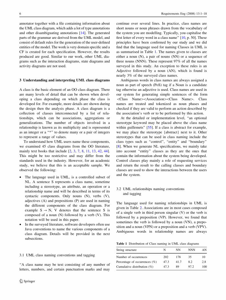
as summarised in Table 1. The names given to classes are
either a noun (N), a pair of nouns (NN) or a sequence of
three nouns (NNN). These represent 97% of all the names
surveyed in this study. An exception to these rules is an
Adjective followed by a noun (AN), which is found is
nearly 3% of the surveyed class names.
Ambiguous words in class names are always assigned a
noun as part of speech (PoS) tag if a Noun is a candidate
tag otherwise an adjective is used. Class names are used in
our system for generating simple sentences of the form
\Class Name[\Association[\Class Name[. Class
names are treated and tokenized as noun phases and
checked if they are valid to perform an action described by
the association’s verb or to be performed by this action.
At the detailed or implementation level, ‘‘an optional
stereotype keyword may be placed above the class name
within guillemets’’ [55]. If a class is abstract for example,
we may place the stereotype {abstract} next to it. Other
stereotypes that can be used in class naming include the
class types such as ‘‘control’’, ‘‘entity’’ and ‘‘boundary’’
[8]. When we generate NL specifications, we mainly take
into account ‘‘entity’’ classes as they are the ones that
contain the information about the system being developed.
Control classes play mainly a role of requesting services
and return the result to the calling classes and boundary
classes are used to show the interactions between the users
and the system.
3.2 UML relationships naming conventions
and tagging
The language used for naming relationships in UML is
given in Table 2. Associations are in most cases composed
of a single verb in third person singular (V) or the verb is
followed by a preposition (VP). However, we found that
sometimes the verb is followed by a noun (VN), a prepo-
sition and a noun (VPN) or a preposition and a verb (VPV).
Ambiguous words in relationship names are always
Table 1 Distribution of Class naming in UML class diagrams
String structure N NN NNN AN
Number of occurrences 202 178 35 10
Percentage of occurrences (%) 47.3 41.7 8.2 2.8
Cumulative distribution (%) 47.3 89 97.2 100
6 Requirements Eng (2008) 13:1–18
123

assigned a Verb as PoS tag if a Verb and a Noun are
candidate tags and if the element is in the first position of
the string name. If the element is in the second position,
then it is assigned a Noun PoS. The verb is used in the
generation process to verify that certain noun phrases are
allowed to perform or performed by the action described by
the verb.
The multiplicity of the relationships is used to associate
articles to the generated noun phrases and these are based
on Meziane’s work [49]. This is summarised in Table 3
where a = {1,2,...,n, *}, b = {1,2,...,m, *}, n and m are
natural numbers and ‘‘pl’’ and ‘‘sg’’ stands for plural and
singular, respectively.
3.3 UML class attributes naming conventions
and tagging
‘‘An attribute name may be text, just like a class name. In
practice, an attribute name is a short noun or noun phrase
that represents some property of its enclosing class. Typi-
cally, you capitalise the first letter of every word in an
attribute name except the first letter’’ [10, p. 50]. These
principles are again verified by our study. The most fre-
quently used strings for naming attributes in UML class
diagrams are shown in Table 4. As it can be observed,
nouns are frequently used and 85% of the strings are single
nouns (N), pair of nouns (NN), triplets of nouns (NNN) or a
noun preceded by an adjective (AN). Verbs are rarely used
and if used, they are in the past tense. Only the verb ‘‘be’’ is
found to be used in some cases in the present tense and
only in the first position of verb–adjective (VA) strings and
they usually denote attributes of type Boolean, such as the
attribute ‘‘isElligible’’. However, there is less then 1% of
such occurrences. We also noted that verbs can occur in
any position of the string where they appear; however, they
occur in the first position in 94% of the strings. Other
naming strings for attributes which percentage of occur-
rences is less then 1% include strings of the form
adjective–noun–noun (ANN), noun–preposition–noun
(NPN), verb–noun–adjective (VNA), verb–noun–noun
(VNN) and verb–preposition–verb (VPV).
The following are some examples of attributes and their
parsing structures: cost (N), timeCompleted (NV), over-
allCost (AN), completionDateSet (NNV). Most of these
strings are ambiguous, i.e. ‘‘completionDateSet’’ is
ambiguous since ‘‘date’’ may be a verb or a noun, and
‘‘Set’’ may be a verb or a noun. Based on the identified
strings used for naming class attributes, we developed the
following rules:
A1. If an element is ambiguous and the string size is 1
then assign the ambiguous word the PoS tag:
(a) Verb if candidate tag is a verb in the past tense
(b) Noun otherwise
A2. If the last element is ambiguous, assign the ambig-
uous word the PoS tag:
(a) Verb, if candidate tags are a verb in past tense
and an adjective.
(b) Noun, if candidate tags are a noun and a verb in
present tense or a noun and an adjective.
A3. If an element is ambiguous and the next element is a
verb, assign the ambiguous word the PoS tag noun.
A4. If a candidate tag is an adjective or verb in the past
then select adjective
A5. If an element is ambiguous and the previous element
is an adjective, then select a noun.
A6. If an element is ambiguous and candidate tags are a
noun and a verb in the present tense, then select a
noun.
Based on these rules we can show how ambiguous
strings are uniquely interpreted. For example the string
‘‘campaignStartDate’’ has eight possible interpretations:
NNN, VNN, NVN, NNV, VVN, VNV, NVV and VVV. By
using rules A2 and A6 respectively, the string is disam-
biguated and is interpreted as NNN.
Table 2 Distribution of relationship naming in UML class diagrams
String structure V VP VPN VN VPV
Number of occurrences 110 31 6 5 3
Percentage of occurrences (%) 66.7 18.8 3.7 3 1.8
Cumulative distribution (%) 66.7 85.5 89.2 92.2 94
Table 3 Translating cardinalities into articles
Form Values Translation
a a = 1 The + sg
a = 2,3,…,n Two, three,…, many + pl
a = * Many + pl
a…b a = 1,2,…,n b = * a = One, two,…,n b = many + pl
a = 2,3,…,n b = a + 1,
a + 2,…,ma = Two, three,…,n b = three,
four, m + pl
Table 4 Distribution of class attributes naming in UML class
diagrams
String structure N NN AN NNN NV VA NNNN
Number of occurrences 504 402 168 111 50 48 41
Percentage of
occurrences (%)
36.5 29.1 12.1 8 3.6 3.5 3
Cumulative
distribution (%)
36.5 65.6 77.7 85 88.6 92.1 95.1
Requirements Eng (2008) 13:1–18 7
123
3.4 UML class operations naming conventions
and tagging
‘‘An operation name may be text, just like a class name. In
practice, an operation name is a short verb or verb phrase
that represents some behaviour of its enclosing class.
Typically, you capitalize the first letter of every word in an
operation name except the first letter.’’ [10, p. 51]. These
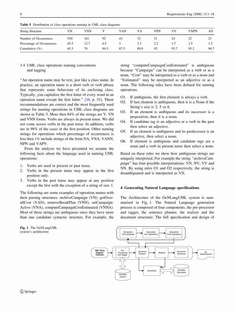
recommendations are correct and the most frequently used
strings for naming operations in UML class diagrams are
shown in Table 5. More then 84% of the strings are V, VN
and VNN forms. Verbs are always in present tense. We did
not come across verbs in the past tense. In addition, verbs
are in 98% of the cases in the first position. Other naming
strings for operations which percentage of occurrences is
less then 1% include strings of the form NA, VNA, VANN,
NPN and VAPV.
From the analysis we have presented we assume the
following facts about the language used in naming UML
operations:
1. Verbs are used in present or past tense.
2. Verbs in the present tense may appear in the first
position only.
3. Verbs in the past tense may appear at any position
except the first with the exception of a string of size 1.
The following are some examples of operation names with
their parsing structures: archiveCampaign (VN), getOver-
allCost (VAN), removeBreakPlan (VNN), setCampaign-
Active (VNA), computeCampaignCostEstimated (VNNA).
Most of these strings are ambiguous since they have more
than one candidate syntactic structure. For example, the
string ‘‘computeCampaignCostEstimated’’ is ambiguous
because ‘‘Campaign’’ can be interpreted as a verb or as a
noun, ‘‘Cost’’ may be interpreted as a verb or as a noun and
‘‘Estimated’’ may be interpreted as an adjective or as a
noun. The following rules have been defined for naming
operations.
O1. If ambiguous, the first element is always a verb.
O2. If last element is ambiguous, then it is a Noun if the
String’s size is 2, 5 or 6.
O3. If an element is ambiguous and its successor is a
preposition, then it is a noun.
O4. If candidate tag is an adjective or a verb in the past
then select an adjective.
O5. If an element is ambiguous and its predecessor is an
adjective, then select a noun.
O6. If element is ambiguous and candidate tags are a
noun and a verb in present tense then select a noun.
Based on these rules we show how ambiguous strings are
uniquely interpreted. For example the string ‘‘archiveCam-
paign’’ has four possible interpretations: VN, NV, VV and
NN. By using rules O1 and O2 respectively, the string is
disambiguated and is interpreted as VN.
4 Generating Natural Language specifications
The Architecture of the GeNLangUML system is sum-
marised in Fig. 1. The Natural Language generation
process is composed of four components, the pre-processor
and tagger, the sentence planner, the realizer and the
document structurer. The full specification and design of
Table 5 Distribution of class operations naming in UML class diagrams
String Structure VN VNN V VAN VA VPN VV VNPN AN
Number of Occurrences 930 181 92 43 33 31 24 22 21
Percentage of Occurrences 65.3 12.7 6.5 3 2.3 2.2 1.7 1.5 1.5
Cumulative (%) 65.3 78 84.5 87.5 89.8 92 93.7 95.2 96.7
Generationfrom Attributes
Generationfrom Operations
GenerationFrom Operations
Pre-Processingand Tagger
SentencePlanner Realizer
DocumentStructurer
Semantics
WordNetLexicon
WordNetSemantics
NLSpecifications
UML ClassDiagramInterface
Fig. 1 The GeNLangUML
system’s architecture
8 Requirements Eng (2008) 13:1–18
123

the GeNLangUML system is described in [6]. The fol-
lowing sections describe each of these components.
4.1 The UML class diagram interface
The inputs to the system are UML class diagrams. A tool
for drawing the components of an UML class diagram was
developed and supports the following five menus: File,
Draw, Move, Edit and Delete. The file menu is used for
saving and loading a project. The draw menu enables users
to draw the components of a class diagram and includes
tools to draw classes and objects, class attributes, class
operations and the relationships between classes. The move
menu allows users to move classes and relationships within
the drawing area. The edit menu is used for editing and
updating the class diagram components. The delete menu
allows the deletion of class diagram components.
We use XML as the internal representation for the UML
class diagrams. Each class diagram is saved using two files.
One file to store the classes, their attributes and operations
and the other file is used to store the relationships between
classes.
4.2 Pre-processing and tagging
Ambiguity in NL has been a major problem in NL pro-
cessing. An input is ambiguous if there are multiple
alternate linguistic structures that can be built for it. A NL
processing system should always select a part-of speech
(PoS) for a given input. The mechanism for assigning a
PoS or other lexical class marker is known as tagging.
Restriction of the input language may result into fewer
ambiguities as the input’s variation is limited. Controlled
languages [23, 63] have been in wide use in the last dec-
ades and have bin Machine Translation Systems [54] and
helped to reduce the amount of ambiguities in domain-
specific applications [29]. The introduction of controlled
languages serves as a justification to our research that a
subset of NL will be less ambiguous than the whole NL,
allowing us to successfully resolve ambiguous strings
without applying a sophisticated tagger.
A simple algorithm for tagging will be to choose the
interpretation that occurs most frequently in the training set
and this is shown to achieve 90% success [26] when half of
the words in the corpus used, are not ambiguous. We
should wonder what will happen if more than half of the
words are ambiguous in a given corpus. The authors in [26]
suggest that we could probabilistically derive the tag for an
ambiguous word given the previous word’s tag, this model
is also known as the bigram model. We could also look at
the two previous tags, and this is known as the trigram
model, to derive the word’s tag. For instance in the sen-
tence ‘‘I am going to fly to Athens tomorrow’’, we could
ask, what is the probability of a fly being a verb with the
previous word (to) being a preposition. Clearly, if the
probability of a verb being the PoS tag is the highest then
the system will have made the right choice. These types of
taggers are known as probabilistic taggers.
Similarly we could use a set of rules to disambiguate
PoS and these are known as rule based taggers. A rule
based PoS tagger suggests the creation of a set of condi-
tions that will limit the chances of having a word being
ambiguous. A rule-based tagger will be composed of a set
of rules. For instance, for the sentence ‘‘I am going to fly
tomorrow’’ an example of rule to resolve the ambiguous
word ‘‘fly’’ will be as follows:
‘‘If a word is ambiguous and the previous word is a
preposition then select a verb.’’
Another category of taggers, is the transformation-based
taggers. In contrast with probabilistic taggers, in the
transformation-based taggers each word has a set of
possible tags that can occur, with the most probable tag
highlighted. A set of rules such as ‘‘Change tag to B if
previous is A’’ is also defined. Brill’s [12] tagger is an
example of transformation-based taggers, and its accuracy
is around 95%. Brill also suggested a mechanism for
deriving tags for unseen words (words that were not found
in the lexicon).
Overall, probabilistic taggers may produce better
results from rule based but probabilistic taggers are
indirectly referring to linguistic information via the access
of probability tables [12]. Rule based taggers require time
for the design of the rules, but they do not require any
tables or corpus or training and could perform quite well
in specific domains where linguistic input is constrained.
In cases, where an appropriate corpus is difficult to find or
training is difficult to perform then a rule based tagger is
the right choice and this is the rational for adopting a rule
based tagger for our system. In addition, it is impossible
to use probabilistic and transformation-based taggers as
they are based on documents that obey NL grammar
rules. Any tagging mechanism based on NL documents
will be invalid since UML class diagrams grammar rules
are different.
4.3 The sentence planner
The sentence planner component receives the tags and the
corresponding words from the tagger and generates sen-
tences following a template based approach where
sentences are generated from combining words in attri-
butes, operations, classes and associations names as
Requirements Eng (2008) 13:1–18 9
123

described in the following subsections. The general
approach is given in Fig. 2.
4.3.1 Generating from attributes
For all attributes within a given object the following three
routines are applied:
4.3.1.1 Formation of ‘‘has’’ sentences (‘‘object name’’ has
‘‘attribute’’) The generator tokenizes the object name and
the attributes, which are expected to be Noun Phrases
(sometimes represented as simple nouns). Then the two
Noun Phrases (the object name and attribute name) form a
sentence with the verb ‘‘has’’ being the main verb. In
Fig. 3a, ‘‘Campaign’’ and ‘‘overallCost’’ will generate
‘‘Campaign has an overall cost’’. This rule always involves
the use of the class name as the subject of the verb and
covers attributes of the form N, NN, NNN, NNNN and AN.
4.3.1.2 Formation from verbs at first position (‘‘verb’’
‘‘right Noun Phrase’’ or ‘‘object name’’) This routine is
applied whenever an attribute has a verb in its first position.
A verb refers to the Noun Phrase on the right or to the
object name if there is no Noun Phrase. The routine
combines the verb and the right Noun Phrase or the object
name to form a sentence. In Fig. 3b, ‘‘Campaign’’ and
‘‘completed’’ will generate ‘‘complete campaign’’. This
rule involves the use of the class name and covers attributes
of the form VA.
4.3.1.3 Generating from verbs elsewhere (‘‘verb’’ ‘‘right
Noun Phrase’’ or ‘‘left Noun Phrase’’) This routine tok-
enizes the verb and proceeds by examining whether there is
a Noun Phrase to the right of the verb and if it exists it
tokenizes it. If there is no Noun Phrase to the right of the
verb the routine examines whether a Noun Phrase is on the
left of the verb and if it exists it tokenizes it. Then a sen-
tence is formed with the verb and the right or the left Noun
Phrase. In Fig. 3c, the sentence ‘‘estimate cost’’ will be
generated. This rule usually does not involve the use of the
class name and covers attributes of the form NV.
4.3.2 Generating from operations
The following routines are applied to the class operations
for sentence generation:
4.3.2.1 Generating a sentence from a verb in the first
position (verb object name) The generator checks whe-
ther there is a Noun Phrase to the right of the verb, if there
is it combines the two together otherwise it combines the
verb with the object name. In Fig. 4a the sentence ‘‘vali-
date campaign’’ is generated. This is usually used with
operations having the structure V, VN, VNN, VPN, etc.
4.3.2.2 Generating from verb elsewhere (‘‘verb’’ ‘‘right
Noun Phrase’’ or ‘‘left Noun Phrase’’) This routine tok-
enizes the verb (not in the first position) and proceeds by
examining whether there is a Noun Phrase to the right of
the verb and if it exists it tokenizes it otherwise the routine
examines whether there is a Noun Phrase to the left of the
verb and if there is, it tokenizes it. Then a sentence is
formed with the verb and the right or the left Non Phrase.
In Fig. 4b the following sentence is generated ‘‘add cost
estimated’’. This rule is usually used with operations hav-
ing the structures VV, VNV, AV, etc.
4.3.2.3 Planning from all words in operations This rou-
tine uses all words in an operation name. It expects a verb
in the first position, and it checks whether a preposition
follows immediately after the verb. If the condition is true,
it adds the object name after the verb and then the rest of
For all classes {
For all attributes {
// generate from attributes routines
}
For all operations {
// generate from operations routines
}
}
For all associations {
// generate from associations routines
}
Fig. 2 General description of the sentence planner
Campaign
estimatedCostoverallCostcompleted
estimateCostaddCostEstimatedvalidate
(a)
Campaign
estimatedCostoverallCostcompleted
estimateCostaddCostEstimatedvalidate
(b)
Campaign
estimatedCostoverallCostcompleted
estimateCostaddCostEstimatedvalidate
(c)
Fig. 3 Generating sentences from class attributes
10 Requirements Eng (2008) 13:1–18
123

the words in the operation. In Fig. 4c the following sen-
tence is generated ‘‘add income to estimated balance’’. This
rule is used with the remaining operations such as those
having the structure VPVN.
4.3.3 Generating from relationships
There are three fundamental types of relationships in OO:
Associations, Aggregations and Generalizations. An asso-
ciation is a functional relationship between two or more
objects such as ‘‘Professor teaches a module’’. An aggrega-
tion, also known as ‘‘part-of’’ or ‘‘part/whole’’ relationships,
are used to denote that one object is ‘‘part/whole’’ of another
object for example to represent a relationship between a
lecture and a module. A generalisation, also know as ‘‘kind-
of’’ relationships, denote that one object is a special case of
another for example a lecturer is a kind of an academic, the
others can be a professor or an associate professor. Gener-
ating sentences from associations is based on the template
shown in Fig. 5.
For example, if object1 = ‘‘Author’’, object2 = ‘‘Book’’
and the association name = ‘‘writes’’ and the cardinality of
the association is ‘‘1, 1,...,*’’ then the following sentence is
generated ‘‘The author writes one or many books’’.
Sentences generated from aggregations take the form
‘‘whole is composed of parts’’. Using the example given in
Fig. 6a, the sentence ‘‘A module is composed of lectures’’
is generated. Sentences generated from generalisation take
the form ‘‘specific object is a general object’’. Again using
the example given in Fig. 6b, the sentence ‘‘a Lecturer is an
academic staff’’ is generated. In our developed system, we
use the capabilities of WordNet [27] to check that the
sentences generated from all relationships are semantically
correct. This is explained in details in Sect. 4.6.
4.4 The realizer
Sentences generated from the sentence planner are fed to the
realizer responsible for ensuring agreement between words
and aggregations. From the analysis on the syntactic varia-
tion of the strings used to name the various components of a
class diagram as described in Sect. 3, agreement should
handle cardinality to noun phrase agreement and noun
phrase to verb agreement. Verbs are either in present tense or
in past participle and this significantly reduces the amount of
morphological rules needed. Aggregation includes subject
grouping where ‘‘has sentences’’ (Sect. 4.3.1.1) are com-
bined together and joint grouping of verb phrases referring to
the same entities. The morphological processor and the
aggregator are described in the following subsections.
4.4.1 Morphological processor
The morphological processor is responsible for cardinality
to noun phrase agreement and for noun phrase to verb
agreement. Cardinality to noun phrase agreement requires
that the sentence planner has set the ‘‘+sg’’ or ‘‘+pl’’
indicators as described in Sect. 3.2 based upon, which the
morphological processor applies changes whenever nec-
essary. If the indicator is set to the ‘‘sg’’ there is no further
processing since WordNet [27] returns the singular form of
the noun. Applying plurality to a noun phrase requires us to
locate the main noun within the noun phrase and then call
the morphological processor. The main noun within a noun
phrase is always the rightmost noun. For example in
‘‘starting date’’ the word ‘‘date’’ is the main noun. For
Campaign
estimatedCostoverallCostcompleted
estimateCostaddCostEstimatedvalidate
(a)
Campaign
estimatedCostoverallCostcompleted
estimateCostaddCostEstimatedvalidate
(b)
Income
addToEstimatedBalance
(c)
Fig. 4 Planning sentences from class operations
Fig. 5 Template used for
generating sentences from
relationships
Lecture
Module
1
*
Academic Staff
Lecturer
(a) (b)
Fig. 6 Generating sentences from aggregations and generalisations
Requirements Eng (2008) 13:1–18 11
123

cardinality to verb agreement the same procedure is fol-
lowed where the main verb is located and then a set of hard
coded rules are applied to the main verb. The verb phrase is
either a verb in present tense or in passive voice. If the verb
is in present tense the ‘‘es’’ or ‘‘s’’ is added to the mor-
pheme returned by WordNet. If the verb is in the passive
voice form the verb ‘be’ changes to either ‘‘is’’ or ‘‘are’’.
The rules of the morphological processor are hard coded
within the application.
4.4.2 The Aggregator
The Aggregator receives the sentences from the morpho-
logical processor and performs joint grouping of ‘‘has
sentences’’ and joint grouping of verb phrases that refer to
the same entity. More specifically the sentence planner
has already integrated sentences generated within the
same object so that joint grouping is performed only to
sentences referring to the same object name. An example
of joint grouping of ‘‘has sentences’’ is the formation of
‘‘car has wheels and windows’’ from ‘‘car has wheels’’
and ‘‘car has windows’’. An example of combining verb
phrases referring to the same entities is the formation of
‘‘estimate and calculate cost’’ from ‘‘calculate cost’’ and
‘‘estimate cost’’. Figure 7 shows the pseudo code for the
aggregator.
4.5 The document structurer
The final step before the sentences are displayed, struc-
tures the generated sentences into an output in a more
readable format. Sentences are processed with associations
first generated and sentences referring to the same enti-
ties generated immediately after. In that way, sentences
referring to the same entities are generated at the same
time, so there is a flow in the generated text. The pseudo-
code given in Fig. 8 summarises the routine we have
implemented.
4.6 Semantics analyser
The semantics component is responsible for verifying that
the generated sentences are semantically correct and dis-
playing related entities to all main nouns of object names in
the UML class diagram. Associations are divided into
simple associations, aggregations and compositions (where
a noun phrase owns another noun phrase), and general-
izations (where a noun phrase is of type noun phrase).
WordNet’s functionality enables the user to display all
hypernyms (kind of) for a given noun. For example if the
user asks for the hypernyms of noun ‘‘professor’’ a list of
hypernyms is returned as shown in Fig. 9. This feature can
be used when verifying generalizations where a noun
phrase (object name) is assumed to be ‘a kind of’ a noun
phrase (another object name). In these cases, we tokenize
the main noun of the noun phrase and get all hypernyms by
accessing WordNet’s database. The list of hypernyms is
compared to the candidate ‘kind of’ noun and if it returns
true the generalization is valid. A similar approach is fol-
lowed in aggregation and composition where a list of
meronyms (part of) of a word are returned from WordNet
and compared to the target noun. Related terms are also
displayed to the user. This mechanism tokenizes all object
names (noun phrases) and proceeds by determining the
main noun for each noun phrase. The system then uses as
an index the main noun and displays the meronyms.
Sentences generated from attributes and operations are
always composed of a verb. The verification of these sen-
tences includes the checking for the validity of certain noun
phrases to follow or precede a specific verb. In WordNet it
is possible to get a set of frames showing the type of words
allowed to precede and/or follow a verb. Figure 10 shows
the sentence frames for the verb ‘‘estimate’’. Given that the
For i to sentence size {
For j=i+1 to sentence size {
If ( sentences have ‘has’ as a verb) {
Compare nouns // subjects
Combine sentences
}
}
}
For i to sentence size {
For j=i+1 to sentence size {
If ( sentences refer to the same entity ) {
Combine sentences
}
}
}
Fig. 7 The pseudo code for the aggregator
For all sentences to display {
For all sentences from associations {
Display sentence from association
If association’s object name equals a noun in a S NP <has> NP sentence{Display sentence
}
}
}
Display the rest of sentences
Fig. 8 Document structurer pseudocode
12 Requirements Eng (2008) 13:1–18
123

sentences generated by our system are mostly of the form
S ? NP, V, NP, the verification of these sentences could
be done by getting the corresponding sentence frames of
the verb and then by checking whether the noun phrase is
of the target type specified by WordNet’s sentence frame.
For example ‘‘Door estimates budget’’ is invalid since
‘‘door’’ is of type something and none of the frames for
verb ‘‘estimate’’ expect a noun phrase of type something to
precede the verb. Also ‘‘manager estimates cost’’ is valid
since manager is of type ‘‘somebody’’ and cost is of type
‘‘something’’. To proceed into the validation step of the
sentences we should categorize noun phrase into three
types. Somebody (manager, professor), something (knife,
window) and social group (university, organization) with
social group being a collection of somebody. To determine
the type of a given noun phrase we extract the main noun
and then get the corresponding meronyms. Then we iterate
through the sentence frames, and validate whether any of
the senses of the noun is of the type specified in the sen-
tence frame. If all noun phrases in a sentence return true for
a given sentence frame it means that the sentence itself is
valid. Else if none of the sentence frames for all noun
phrases return true, then the semantics component outputs a
message with the invalid sentence as well as the set of the
valid sentence frames for the sentence’s verb.
Although it seems reasonable to employ a similar
technique for verifying ‘has sentences’, it turns out that
relationships between attributes and object names are very
general. In UML attributes are assumed to be ‘‘part of’’ an
object, in the sense that it indicates that the attribute resides
within the object’s definition and not necessarily that the
attribute is a part of the entity ‘‘object’’. Consider Fig. 11,
where the class Professor has attributes instructors and
name. This relationship indicates that ‘‘instructors’’ is an
attribute of professor and not part of it. Thus the relation-
ship between these two entities is general and can not be
verified from the meronyms definitions of ‘‘professor’’. In
addition for verbs get, set, change, update and insert we
perform no semantic verification because these actions
imply manipulation of data within an object rather than
manipulation of sub entities within entities. For instance, in
Fig. 11 we could have get instructors (get somebody), get
name (get something), implying that there is a routine to
get the contents of attributes within an object.
Fig. 9 Hypernyms of the word
‘‘professor’’
Fig. 10 Sentence frames for the
verb ‘‘estimate’’
Requirements Eng (2008) 13:1–18 13
123

5 System evaluation
5.1 The case study
To illustrate how our system works and the kind of NL
requirements it generates, we have used a case study taken
from [3] and which class diagram is shown in Fig. 12. It
represents a class diagram for a University system and
involves standard functionalities such as a professor giving
a seminar, a student attending a course, etc. The case study
was chosen by one of the authors and contains the kind of
information and complexity our system can deal with at
this development stage. In [3], the case study was described
through a set of use cases from which the class diagram
was derived. Hence it was not possible to compare the
generated NL specifications with the original ones but
comparison can be made with the description of the use
case diagrams. The objective of this evaluation is twofold:
(1) To verify the strings naming used in the class diagram
and compare them with the results obtained from our study
as described in Sect. 3 and (2) to have an idea on the kind
of NL specifications generated by our system.
5.2 String naming compliance
In this case study, class and relationship names are 100%
compatible with the rules defined in Sect. 3. 94.5% of the
attributes are compatible and only 5.5% are not. However,
these were successfully tagged. 89.8% of the operations
names are compatible with the rules. 10.8% of the opera-
tions (4) were found to be of the form VNA, which was not
identified earlier. If we have used a larger sample to derive
the rules in Sect. 3, this might have identified this type of
strings earlier. Table 6 summarises the names distribution
for the case study.
5.3 Evaluation of tagging results
The tagging of the attributes, operations and relationships
between the classes are based on the rules defined in
Sect. 3. The tagged strings are those obtained from the
internal representation of the class diagram. 92.8% of the
strings are compatible with the rules defined in this study
for naming the components of a class diagram. 35.7% of
the strings are ambiguous and our system has assigned the
correct PoS for 84% of these ambiguous strings. This high
accuracy is explained by the high compatibility rates, since
the tagger is designed to efficiently tag strings that comply
with the assumed rules. 16% the ambiguous strings were
not resolved as they were of the form VNA, which was not
included in our initial list of rules, with the adjective being
+getName()+setName()+getInstructors()+setInstructors()
-Name-Instructors
ProfessorFig. 11 Class professor
Fig. 12 The UML class
diagram for the case study
14 Requirements Eng (2008) 13:1–18
123

interpreted as a verb in the past tense. This rule has now
been added to our list of rules.
5.4 Evaluation of the generator
We were able to generate sentences describing most of the
information from the case study class diagram. In fact, the
structure of the lexical base proved complete for verifying
the meaning and generating NL from operations and
attributes. Since most operations are composed of a single
verb, the decision to perform a verb-based search to match
an entry in the lexical base was sufficient. For attributes,
we verified all relationships between all nouns in a given
object, and generated sentences such as ‘‘professor has
date’’. For associations we were able to generate sentences,
by verifying that a ‘‘noun’’ may perform action ‘‘verb’’ and
this action ‘‘verb’’ may be performed to another ‘‘noun’’.
We also applied transformations to verbs into third person
in singular, where necessary and combined already gen-
erated sentences. The sentence ‘‘get full name’’ is a result
of combining the frame ‘‘get name’’ with the adjective-
noun entry ‘‘full name’’. However, we were unable to
generate the correct information from incorrectly resolved
strings. ‘‘addSeminarOverseen’’ generates ‘‘add seminar’’
instead of ‘‘add Overseen Seminar’’. ‘‘Overseen’’ was
tagged as a verb, thus the system does not check for veri-
fication of the ‘‘overseen-seminar’’ pair having as a result
the omission of the word ‘‘overseen’’ from the generated
sentence. A rule is added for future versions of the system.
Figure 13 shows part of the NL specifications generated by
the GeNLangUML system for the case study.
5.5 Conclusions and lessons learnt
The evaluation of the proposed system has shown both
the strengths and weaknesses of our system. In terms of
naming the classes, their attributes and operations and
the relationships, the results obtained are consistent with
those of our study. At least, within the academic com-
munity, there seems to be some kind of consensus on
how to name the various components of a class diagram.
Although, the generated NL should be understandable by
most users, it still remains at the same level of
abstraction as the class diagram. Hence, some users may
require some basic understanding of OO concepts to
make sense of the generated NL specifications. For those
who can understand OO concepts, the generated NL
specifications are similar to the language used in the
Table 6 Case study naming distribution
Rules Classes Relations Attributes Operations
N AN NNN VP V N NN NA oth VN VNN V oth
# 7 1 1 3 2 11 6 1 1 22 10 1 4
% 77.8 11.1 11.1 60 40 61.1 33.3 5.5 5.5 59.4 27 2.7 10.8
Fig. 13 A sample of the
generated Natural Language
specifications
Requirements Eng (2008) 13:1–18 15
123

description of the use cases used for the development of
the class diagram in [3].
6 Conclusion and future developments
In this paper, we presented the GeNLangUML system that
generates NL specifications from UML class diagrams. We
studied 45 class diagrams, all academic and taken from text
books, to understand the most commonly used rules and
conventions used by software developers when naming
various components of a class diagram. A set of rules based
on the syntactic structures of the string names has been
developed taking into account statistical information.
These rules were used to understand and disambiguate the
names given to classes, relationships, attributes and oper-
ations in a UML class diagram. We used WordNet for the
syntactic analysis of the input names and the verification of
sentences generated. The system was evaluated using an
independent case study. The results obtained so far are
encouraging and the implemented prototype demonstrated
its feasibility. If fully implemented, such a system will
undeniably help software engineers in generating NL
specifications from class and other UML diagrams to use
for communicating with those stakeholders who cannot
understand UML models. These can also be used as a way
of integrating users in the consistency checking process
when changes are made to the design or implementation.
As mentioned earlier, tools such as Rational Rose (http://
www-306.ibm.com/software/rational) can reverse engineer
code to UML diagrams and systems such as GeNLan-
gUML will help the generation of NL specifications from
UML diagrams.
However, in its current state, our system presents few
weaknesses and further developments should address the
following issues.
1. This research is purely developed in an academic
environment. The examples used to statistically sam-
ple the naming conventions in UML class diagrams are
taken from academic books as is the final example
used to evaluate the system. In industry, this might be
completely different as various organizations may
have different conventions in naming the class dia-
grams components. For example they may use
abbreviations such as ‘‘DoB’’ instead of ‘‘DataOf-
Birth’’, the linking of a class name to a module or
subsystem as in ‘‘PM-CustomerName’’ to show that
the customer name is related to the purchase module
(PM) or the linking of an attribute to its class name.
However, when developing software projects a data
dictionaries are often used and these would contain
entries to the class and attributes names in particular.
Hence, future developments of the system should take
into account data dictionaries and use them to com-
plement the information already available in the class
diagrams.
2. The NL generated remains at a level of abstraction
similar to that of the original class diagram. Hence,
some users may still need to understand some OO
concepts to make sense of the generated specifications.
At this stage, our system can be used as a tool for
teaching requirements engineering and OO modelling.
This will help students to have different views of the
same model. Further development of the system should
improve the generated requirements by solving more
ambiguous string and improve their final structure to
make them more readable and close to the way NL
requirements are written.
3. Class diagrams are not the only models developed
during software specification and design, use cases,
interaction diagrams and state diagrams should also be
looked at as they may enrich the generated NL
requirements.
4. The work on translating OCL to NL reported in the
literature review section can be used to complement
our work.
Acknowledgments The authors would like to thank the anonymous
referees for their helpful comments, suggestions and insightful
questions that helped improve the content and structure of this paper.
References
1. Abbott A (1983) Program design by informal English description.
CACM 16(11):882–894
2. Ambler SW (2001) The object primer, the application devel-
oper’s guide to object orientation and the UML. Cambridge
University Press, Cambridge
3. Ambler SW (2004) The object primer, Agile—model driven
application development with UML 2.0, 3rd edn. Cambridge
University Press, Cambridge
4. Ahrendt W, Baar T, Beckert B, Bubel R, Giese M, Hahnle R,
Menzel W, Mostowski W, Roth A, Schlager S, Schmitt PH
(2005) The KeY tool. Softw Syst Model 4(1):32–54
5. Ambriola V, Gervasi V (2003) The CIRCE approach to the
systematic analysis of natural language requirements, Technical
Report TR03 -05, University of Pisa, Dipartimento di Informat-
ica, March 2003, http://citeseer.ist.psu.edu/ambriola03circe.html
6. Athanasakis N (2006) Generating natural language from UML
class diagrams. Master Thesis, University of Salford, School of
Computing, Science and Engineering, UK
7. Barclay KA, Savage J (2003) Object-oriented design with UML
and JAVA, Butterworth-Heinemann Ltd
8. Bennet S, Mcrobb S, Fenter R (2002) Object oriented systems
analysis and design using UML, 3rd edn. Mc Graw Hill,
9. Booch G (1986) Object Oriented development. IEEE Trans Softw
Eng 12(2):211–221
10. Booch G, Rumbaugh J, Jacobson I (1999) The Unified modeling
language user guide, Addison-Wesley, Reading
16 Requirements Eng (2008) 13:1–18
123

11. Booch G (2003) Object oriented analysis and design with appli-
cations, Addison-Wesley, Reading
12. Brill E (1995) Transformation-based error-driven learning and
natural language processing: a case study in part-of-speech tag-
ging. Comput Linguist 21(4):543–565
13. Bruegge B, Dutoit AH (2003) Object-oriented software engi-
neering: using Uml, patterns and Java: International Edition,
Prentice-Hall, Englewood Cliffs
14. Burke DA (2004) Improving the natural language translation of
formal software specifications, Master Thesis, Chalmers
University of Technology, Gothenburg, Sweden
15. Burke D, Johannisson K (2005) Translating formal software
specifications to natural language: a grammar-based approach. In:
Proceedings of the logical aspects of computational linguistics
conference, Bordeaux, France, April 2005, pp 51–66
16. Caldwell DE, Korelsky T (1994) Bilingual generation of job
descriptions from quasi-conceptual forms. In: Proceedings of the
4th ACL conference on applied natural language processing,
Stuttgart, pp 1–6
17. Caragno D, Iordanskaja L (1989) Content determination and text
structuring in Gossip. In: Extended abstracts of the 2nd European
natural language generation workshop, University of Edinburgh,
pp 15–21
18. Chen PPS (1976) The entity-relationship model : toward a unified
view of data. ACM Trans Database Syst 1(3):9–36
19. Chen PPS (1983) English sentence structure and entity-relation-
ship diagrams. Inf Syst 29:127–149
20. Cheng BHC, Campbell LA (2001) Integrating informal and for-
mal approaches to requirements modeling and analysis, In:
Proceedings of the 5th international symposium on requirements
engineering, Toronto, Canada, pp 294–295
21. Christel MG, Kang KC (1992) Issues in requirements elicitation,
Technical Report CMU/SE1–92-TR-12 ESC-TR-92–012, Soft-
ware Engineering Institute, Carnegie Mellon University
Pittsburgh, Pennsylvania 15213
22. Dalianis H, Hovy E (1993) Aggregation in natural language
generation. In: Lecture notes in computer science, vol 1036,
Springer, Heidelberg, pp 88–105
23. Danlos L, Lapalme G, Lux V (2000) Generating a Controlled
Language. In: Proceedings of the first international conference on
Natural language generation, vol 14. Mitzpe Ramon, Israel, pp
141–147
24. Davis AM (1990) Software requirements analysis and specifica-
tion, Prentice-Hall, Englewood Cliffs
25. Dunn L, Orlowska M (1990) A natural language interpreter for
construction of conceptual schemas. In: Proceedings of the 2nd
Nordic conference on advanced information systems engineering,
Springer, Heidelberg, pp 371–386
26. Eugenio DB, Glass M, Trolio M (2002) The DIAG Experiments:
NLG for intelligent tutoring systems. In: Proceedings of the
AAAI spring symposium on natural language generation in
spoken and written dialogue, pp 120–127
27. Fellbaum C (ed) (1998) WordNet: an electronic lexical database,
MIT Press, Cambridge. http://wordnet.princeton.edu/
28. Fickas S (1987) Automating the analysis process. In: Proceedings
of 4th IEEE international workshop on software specification and
design, Monterey, pp 58–67
29. Gervasi AV, Zowghi AD (2005) Reasoning about inconsistencies
in natural language requirements. ACM Trans Softw Eng Meth-
odol 14(3):277–330
30. Goldberg E, Driedger N, Kitteridge R (1994) Using natural lan-
guage processing to produce weather forecasts. IEEE Expert
9(2):45–53
31. Goldin L, Berry DM (1997) AbstFinder, A prototype natural
language text abstraction finder for use in requirements elicita-
tion. Autom Softw Eng 4(4):375–412
32. Harmain HM (2000) Building Object-Oriented conceptual
models using natural language processing techniques, PhD
Thesis, Department of Computer Science, University of Shef-
field, UK
33. Harmain HM, Gaizauskas R (2003) CM-Builder: A natural lan-
guage-based CASE tool for object-oriented analysis. Autom
Softw Eng J 10(2):157–181
34. Heitmeyer CL, Jeffords RD, Labaw BC (1996) Automated con-
sistency checking of requirements specifications. ACM Trans
Softw Eng Methodol 5(3):231–261
35. Horacek H (1992) An integrated view of text planning. In:
Aspects of automated natural language generation, Lecture notes
in artificial intelligence, vol 587. Springer, Berlin, pp 29–44
36. Johannisson K (2005) Formal and Informal Software Specifica-
tions. PhD Thesis, Department of Computing Science, Gotenborg
University
37. Jones CB (1990) Systematic software development using VDM,
Prentice-Hall, Englewood Cliffs
38. Kof L (2006) Text analysis for requirements engineering, PhD
Thesis, Institut fur Informatik der Technischen Universitat
Munchen, Germany
39. Konrad S, Cheng BHC (2005) Automated analysis of natural
language properties for UML models. MoDELS Satellite Events,
pp 48–57
40. Lavoie B, Rambow O, Reiter E (1996) The ModelExplainer. In:
Proceedings of the 8th international workshop on natural lan-
guage generation, England, pp 9–12
41. Lethbridge T, Singer J, Forward A (2003) How software engi-
neers use documentation: the state of the practice, IEEE
Software, pp 35–39
42. Lethbridge T, Laganiere R (2004) Object-oriented software
engineering: practical software development using UML and
Java, McGraw-Hill, New York
43. Lubars MD, Harandi MT (1986) Intelligent support for software
specification and design. IEEE Expert 1(4):33–41
44. Maciaszek LA (2001) Requirements analysis and system design,
developing information systems with UML, Addison-Wesley,
Reading
45. Mann WC, Moore JA (1980) Computer as author—results and
prospects, Technical Report RR-79–82. USC Information Sci-
ence Institute, Marina del Rey
46. Martin-Lof P (1984) Intuitionistic type theory. Bibliopolis,
Napoli
47. Kajko-Mattsson M (2001) The state of documentation practice
within corrective maintenance. In: Proceedings of the IEEE
international conference on software maintenance, ICSM, pp
354–363
48. Mckeown K, Kukich K, Shaw J (1994) Practical issues in auto-
matic documentation generation. In: Proceedings of the 4th
conference on applied natural language processing, Stuttgart, pp
7–14
49. Meziane F (1994) From English to formal specifications, PhD
Thesis, University of Salford
50. Mich L (1996) NL-OOPS: from natural language to object ori-
ented requirements using the natural language processing system
LOLITA. Nat Lang Eng 2(2):161–187
51. Moore J, Paris C (1989) Planning text for advisory dialogues. In:
Proceedings of the 27th annual meeting of the association for
computational linguistics, pp 203–211
52. Moreno AC, Juristo N, Van RP de Riet (2002) Formal justifica-
tion in object-oriented modelling: a linguistic approach. Data
Knowledge Eng 33(2):25–47
53. Nuseibeh B, Easterbrook S (2000) Requirements engineering: a
roadmap, In: Proceedings of the international conference on the
future of software engineering, Limerick, Ireland, ACM Press,
New york, pp 35–46
Requirements Eng (2008) 13:1–18 17
123

54. Nyberg EH, Mitamura T (1996) Controlled language and
knowledge-based machine translation: principles and practice. In:
Proceedings of the first international workshop on controlled
language applications
55. OMG, Unified Modeling Language Specification, version 1.5 (http://
www.uml.org)
56. Overmeyer SP, Lovoie B, Rambow O (2001) Conceptual mod-
eling through linguistic analysis using LIDA. In: Proceedings of
the 23rd international conference on software engineering,
Toronto, Canada, pp 401–410
57. Paiva DS (1998) A survey of applied natural language generation
systems, Information Technology Research Institute Technical
report Series, University of Brighton
58. Presland G (1996) The analysis of natural language requirements
documents, PhD thesis, University of Liverpool
59. Reiter E, Mellish C, Levine J (1992) Automatic generation of on-
line documentation in the IDAS project. In: Proceedings of the
3rd conference on applied natural language processing, pp 64–71
60. Reiter E (1995) NLG vs. Templates. In: Proceedings of the 5th
European workshop on natural language generation, Leiden, The
Netherlands, pp 95–105
61. Richard K, Mel’cuk I (1983) Towards a computable model of
meaning text relations within a natural sublanguage. In:
Proceedings of the 8th international joint conference on artificial
intelligence (IJCAI-83), Karlsruhe, West Germany, pp 657–659
62. Saeki M, Horai H, Toyama K, Uematsu N, Enomoto H (1987)
framework based on natural language, In: Proceedings of the 4th
IEEE international workshop on software specification and
design, Monterey, pp 87–94
63. Schwitter R (2002) English as a formal specification language,
Proceedings of the 13th international workshop on database and
expert systems applications, IEEE Computer Society, Washing-
ton, DC, USA, pp. 228–232
64. Shaw J (1995) Conciseness through aggregation in text genera-
tion. In: Proceedings of the 33rd ACL, pp 329–331
65. Spivey M (1992) The Z notation: a reference manual, 2nd edn.
Prentice-Hall International
66. Wahlster W, Andre E, Bandyopadhyay S, Winfried G, Rist T
(1991) WIP: the coordinated generation of multimodal presen-
tations from a common representation. In: Stock O, Slack J,
Ortony A (eds) Computational theories of communication and
their applications. Springer, Heidelberg, pp 75–93
67. Walden K (1996) Reversibility in software engineering. Com-
puter 29(9):93–95
68. Warmer JS, Kleep AG (1998) The object constraint language:
precise modeling with UML, Addison-Wesley, Reading
18 Requirements Eng (2008) 13:1–18
123


![Robot Behavior Toolkit: Generating Effective Social …Robot Operating System (ROS) [24] module that integrates the be-havioral specifications provided by these findings into an](https://static.fdocuments.us/doc/165x107/5f0b4e667e708231d42fdd8d/robot-behavior-toolkit-generating-effective-social-robot-operating-system-ros.jpg)