General Specifications Insacal Conductivity Master Meter
8
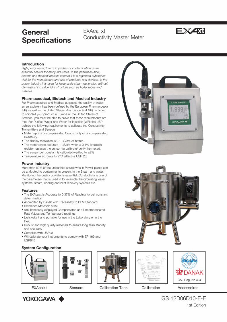
Introduction High purity water, free of impurities or contamination, is an essential solvent for many industries. In the pharmaceutical, biotech and medical devices sectors it is a regulated substance vital for the manufacture and use of products and devices. In the power industry it is used for large scale steam generation without damaging high value infra structure such as boiler tubes and turbines. Pharmaceutical, Biotech and Medical Industry For Pharmaceutical and Medical purposes the quality of water, as an excipient has been defined by the European Pharmacoepia (EP) as well as the United States Pharmacoepia (USP). In order to ship/sell your product in Europe or the United States of America, you must be able to prove that these requirements are met. For Purified Water and Water for Injection (WFI) the USP defines the following requirements to calibrate the Conductivity Transmitters and Sensors • Meter reports uncompensated Conductivity or uncompensated Resistivity. • The display resolution is 0.1 µS/cm or better. • The meter reads accurate 1 µS/cm when a 0.1% precision resistor replaces the sensor (to calibrate/ verify the meter). • The sensor cell constant is calibrated/verified to ±2% • Temperature accurate to 2°C (effective USP 28) Power Industry More than 50% of the unplanned shutdowns in Power plants can be attributed to contaminants present in the Steam and water. Monitoring the quality of water is essential. Conductivity is one of the parameters that is used in for example the circulating water systems, steam, cooling and heat recovery systems etc. Features • The EXAcalxt is Accurate to 0.37% of Reading for cell constant determination • Accredited by Danak with Traceability to DFM Standard • Reference Materials SRM • simultaneously displayed Compensated and Uncompensated Raw Values and Temperature readings • Lightweight and portable for use in the Laboratory or in the Field • Robust and high quality materials to ensure long term stability and accuracy • Complies with USP28 • Will calibrate your instruments to comply with EP 169 and USP645 System Configuration GS 12D06D10-E-E 1st Edition General Specifications EXAcal xt Conductivity Master Meter EXAcalxt Sensors Calibration Tank Calibration Accessoires CAL Reg. Nr. 484
Transcript of General Specifications Insacal Conductivity Master Meter
IntroductionHigh purity water, free of impurities or contamination, is an essential solvent for many industries. In the pharmaceutical, biotech and medical devices sectors it is a regulated substance vital for the manufacture and use of products and devices. In the power industry it is used for large scale steam generation without damaging high value infra structure such as boiler tubes and turbines.
Pharmaceutical, Biotech and Medical IndustryFor Pharmaceutical and Medical purposes the quality of water, as an excipient has been defined by the European Pharmacoepia (EP) as well as the United States Pharmacoepia (USP). In order to ship/sell your product in Europe or the United States of America, you must be able to prove that these requirements are met. For Purified Water and Water for Injection (WFI) the USP defines the following requirements to calibrate the Conductivity Transmitters and Sensors• Meter reports uncompensated Conductivity or uncompensated
Resistivity.• The display resolution is 0.1 µS/cm or better.• The meter reads accurate 1 µS/cm when a 0.1% precision
resistor replaces the sensor (to calibrate/ verify the meter).• The sensor cell constant is calibrated/verified to ±2%• Temperature accurate to 2°C (effective USP 28)
Power IndustryMore than 50% of the unplanned shutdowns in Power plants can be attributed to contaminants present in the Steam and water. Monitoring the quality of water is essential. Conductivity is one of the parameters that is used in for example the circulating water systems, steam, cooling and heat recovery systems etc.
Features• The EXAcalxt is Accurate to 0.37% of Reading for cell constant
determination• Accredited by Danak with Traceability to DFM Standard• Reference Materials SRM• simultaneously displayed Compensated and Uncompensated
Raw Values and Temperature readings • Lightweight and portable for use in the Laboratory or in the
Field• Robust and high quality materials to ensure long term stability
and accuracy• Complies with USP28• Will calibrate your instruments to comply with EP 169 and
USP645
System Configuration
GS 12D06D10-E-E1st Edition
GeneralSpecifications
EXAcal xt Conductivity Master Meter
Insacal Conductivity Master Meter
GS 1-IPP-ICMM2nd Edition www.irishpowerandprocess.com
FEATURES
•
•
•
•
•
GeneralSpecifications
Sensors Calibration Tank Calibration AccessoriesInsacal
System Configuration
For Pharmaceutical and Medical purposes the quality of water, as an excipient has been defined by the European Pharmacoepia (EP) as well as the United States Pharmacoepia (USP). In order to ship/sell your product in Europe or the United States of America, you must be able to prove that these requirements are met.
For Purified Water and Water for Injection (WFI) the USP defines the following requirements:
Meter reports uncompensated Conductivity or uncompensated Resistivity.
The display resolution is 0.1 µS/cm or better.
The meter reads accurate 1 µS/cm when a 0.1% precision resistor replaces the sensor (to calibrate/verify the meter).
The sensor cell constant is calibrated/verified to ±2%
Temperature accurate to 2°C (effective USP 28)
The Insacal is accurate to 0.37% of reading for cell constant determination with a test accuracy ratio of better than 4:1 (accuracy ranges from 0.25% to 1% depending on user measurement range and calibration option)
Accredited by Danak with Traceability to DFM Standard Reference Materials SRM
Compensated and Uncompensated Raw Values and Tempera-ture readings are all simultaneously displayed to ensure accuracy
Lightweight and portable for use in the Laboratory or in the Field
Robust and made from suitable materials to ensure long term stability and accuracy
•
•
•
•
•
ppIIRISH POWER & PROCESS
CAL Reg. Nr. 484
EXAcalxt Sensors Calibration Tank Calibration Accessoires
CAL Reg. Nr. 484

2
GS12D06D10-E-E
General Specifications Model SC450 Conductivity / Resistivity Analyzer
The EXAxt 450 series is designed to combine the superior functionality of the Yokogawa EXA series withthe ease of use offered in Smart Phones and tablets.
Truly unique in the EXAxt 450 series is the Human Machine Interface. The high resolution graphicaldisplay and the touch screen operation make all information visible to the operator. Configuration withthe touch screen is as easy as operating a tablet. Simply choose the language of choice and on screeninstructions assure that the best configuration for the application is obtained.
The EXAxt 450 offers full functionality with PID control on either mA output(s) or on contact output(s).The contact outputs can be selected as pulse frequency controlled or pulse length controlled contactfunction to control chemical metering pumps or solenoid valves.
The SC450G is a family of SMART analyzers: In addition to the two mA outputs a digital HART® signalis superimposed on mA1. This signal supplies up to four process variables and many diagnostic data.This information can be used to generate additional current and contact outputs in the HMI monitor and in maintenance optimization programs like PRM and AMS.
The SC450G offers the best accuracy in the industry by combining the conductivity measurement with advanced temperature compensation functionality, preloaded calibration standards and cell fouling monitoring. The SC450G is universal. The analyzer accepts sensors with cell constants ranging from 0.005 till 50/cm; 2-electrode sensors as well as 4-electrode sensors; 5 different temperature compensating elements for accurate temperature compensation.
The SC450G offers ultra pure water compensation for demineralised water, for Steam, Condensate and Boiler water analysis (Cation Conductivity, Ammonia and Morpholine Conductivity). SC450G also offers Matrix compensation and output linearization for accurate analysis of strong acids and alkalis.
Especially for the Water for Injection Monitoring in the pharmaceutical industry the functionality of USP chapter 645 and EP 0169 has been implemented.
Features• Unique HMI with menu structure and high resolution graphical
display with touch screen• Interactive display with choice out of 8 languages • Trending display for up to 2 weeks• On-screen logbooks store calibration data, configuration changes
and events• Advanced Process Temperature Compensation• USP 645 and EP 0169 limits implemented• Cell fouling monitoring
0.0
0.5
1.0
1.5
2.0
2.5
3.0
3.5
μS/c
m
USPSafety Margin
25 50 75 100˚C
Figure 1 : USP 645 and EP0169 legal conductivity range

3
GS12D06D10-E-E
A. Input specifications : Two or four electrodes measurement with
square wave excitation, using max 60m (200ft) cable (WU40/WF10) and cell constants from 0.005 to 50.0 cm-1
B. Input ranges Conductivity : 0.000 µS/cm - 2000 mS/cm Minimum : 1µS/cm (underrange 0.00 µS x C) Maximum : 200 mS/cm (overrange 2000 mS x C) Resistivity : 0.0 Ω x cm - 1000 MΩ x cm Minimum : 5 Ω/cm (underrange 0.0 Ω/C) Maximum : 1 MΩ/cm (overrange 1000 MΩ/C) Note : “C” means cell constant. Temperature : Pt1000 -20 to 250ºC (0-500ºF)
: Pt100 -20 to 200ºC (0-400ºF) : Ni100 -20 to 200ºC (0-400ºF) : NTC 8k55 -10 to 120ºC (10-250ºF) : Pb36 (JIS NTC 6k) -20 to 120ºC (0-250ºF)
C. Accuracy Conductivity/resistivity : ≤ 0.5 % of reading Temperature : ≤ 0.3ºC (≤ 0.4ºC for Pt100) mA outputs : ≤ 0.02 mA Ambient temperature influence : ± 0.05% /ºC Step respons : ≤ 4 sec for 90% (for a 2 decade step) Note on performance specifications The following tolerance is added to above performance. mA output tolerance: ±0.02 mA of “4-20 mA”D. Transmission signals General : Two isolated outputs of 4-20 mA. DC with
common negative. Maximum load 600 Ω. Bi-directional HART® (HART 5) digital communication, superimposed on mA1 (4-20 mA) signal.
Output Function : Linear or non-linear 21-step table for Conductivity/Resistivity, concentration or temperature
Control function : PID control. Burn out function : Burn up (21.0 mA) or burn down (3.6 mA) to
signal failure acc. NAMUR NE43. : Adjustable damping : Expire time Hold : The mA-outputs are frozen to the last/fixed
value during calibration/ commissioningE. Contact outputs General : Four SPDT relay contacts with display
indicators. Contact outputs configurable for hysteresis and delay time.
Switch capacity : Maximum values 100 VA, 250 VAC, 5 Amps. (*1) Maximum values 50 Watts, 250 VDC, 5 Amps. (*1)
Status : High/Low process alarms, selected from conductivity, resistivity, concentration or temperature. Configurable delay time and hysteresis. PID duty cycle or pulsed frequency control. FAIL alarm
Control function : On / Off : Adjustable damping : Expire time Hold : Contact can be used to signal the hold
situation. Fail safe : Contact S4 is programmed as failsafe
contact. Note *1: When contact output current is more than 4 Amps,
ambient temperature should be less than 40 ºC.
F. Contact Input : Remote range switching to 10 times the programmed range.
Contact open : If impedance > 100 kΩ: 1 x Range (When programmed range for mA output is conductivity)
Contact closed : If impedance < 10 Ω: 10 x RangeG. Temperature compensation
: Automatic or manual, for temperature ranges mentioned under C (inputs).
Reference temp. : programmable from 0 to 100ºC or 30 - 210 °F (default 25ºC).
H. Compensation algorithm : According IEC 60746-3 NaCl tables (default). Two independent user programmable
temperature coefficients, from 0% to 3.5% per ºC (ºF) by adjustment or calibration.
Matrix compensation : With conductivity function of concentration
and temperature. Choice out of 13 preprogrammed matrixes and 2 100-points user-programmable matrices.
I. Calibration : Semi-automatic calibration using pre-configured OIML (KCl) buffer tables, with automatic stability check. Manual adjustment to grab sample.
J. Logbook : Software record of important events and diagnostic data readily available in the display or through HART®.
K. Display : Graphical Quarter VGA (320 x 240 pixels) LCD with LED backlight and touchscreen. Plain language messages in English, German, French, Spanish, Italian, Swedish, Portuguese and Japanese.
L. Form Dimension : 144 (W) x 144 (H) x Approx.144 (D) Converter weight : Approx. 1.5 kgM. Housing : Cast Aluminim housing with chemically
resistant coating; Polycarbonate cover with Polycarbonate flexible window
: Protection IP66 / NEMA 4X / CSA Type 3S Colour : Silver grey SC450G-A(D)-A : IP66 cable glands are supplied with the unit SC450G-A(D)-U : NEMA 4X close up plugs are mounted in
the unused cable entry holes and can be replaced by conduit fittings as required Pipe, Panel or Wall mounting using optional hardware
Optional conduit adapter : G1/2, 1/2NPT or M20 femaleN. Power supply : SC450G-A : Ratings : 100-240 V AC Acceptable range : 90 to 264 V AC Ratings : 50/60 Hz Acceptable range : 50 Hz ±5%, 60 Hz ±5% Power Cons. : 15 VA
O. Safety, EMC and RoHS conforming standards Safety : EN 61010-1 : EN 61010-2-030 : EN 61010-2-201 : CAN/CSA C22.2 No.61010-1 : CAN/CSA C22.2 No.61010-2-030 : CAN/CSA IEC 61010-2-201 : UL 61010-1 : UL 61010-2-030 : UL 61010-2-201 EMC : EN 61326-1 Class A, Table 2 : EN 61326-2-3
General Specifications EXAxt SC450

4
GS12D06D10-E-E
12D7J1-07FLOW TYPE SENSOR
ø 30(1.18")
ø 36(1.42") 10
(0.4
0")
L20
(0.7
8")
30(1
.18"
)43
(1.6
9")
ø d
SC42-EP04 (L= 193 mm)SC42-EP14 (L= 160 mm)SC42-EP08 (L= 193 mm)SC42-EP18 (L= 160 mm)
Unit: mm (inch)
Model Temp. element Cell constant Pressure rating Max. temperature 90% Temp. response Inlet dø Meas. systemSC42-EP08 Pt1000 10 cm-1 10 bar/142 PSIG 110ºC/230 ºF < 3 min. 5 mm 4-el.ectrodeSC42-EP18 Pt1000 1 cm-1 10 bar/142 PSIG 110ºC/230 ºF < 2 min. 10 mm 4-el.ectrode
Fig. X Flow type
The maximum pressure and temperature rating also depend on the actual process conditions. Under certain circumstances it is necessary to test the cell in situ. Additional data is available from Yokogawa.
Epoxy cells for 2- and 4-electrode type with cell-constants 1 and 10 cm-1.These conductivity sensors have a body of glass-filled epoxy resin. The electrodes are made from graphite impregnated with epoxy resin. This gives the sensors a good chemical resistance and a good reduction of polarisation effects.
Features• Good chemical resistance.• Choice in 2- and 4-electrode types.• Easy installation
General SpecificationsMaterialsWetted parts a. Body : Glass filled epoxy resin b. Electrodes : Graphite impregnated with epoxy
resinConnector plug : /M : Material certificate *3.1 Material certficate according EN 10204 is standard delivered with stainless steel version
Weight and immersion length (L in figure)Model SC42-EP0. : 270 gram; 193 mm (L)Model SC42-EP1. : 220 gram; 160 mm (L)
OptionsCertificate /Q : Quality inspection certificate
Functional Specifications
: EN 61000-3-2 Class A : EN 61000-3-3 RCM : EN61326-1 Class A : Korea Electromagnetic Conformity StandardNote: This instrument is a Class A product, and it is designed for
use in the industrial environment. Please use this instrument in the industrial environment only.
RoHS :EN 50581 FM nonincendive approval (suffix code Type: -U) : FM3611 Class I, Div.2, Group ABCD,
T6 for Ta -20 to 55ºC Installation alt. : 2000 m or less Category based on IEC 61010: II (Note) Pollution degree based on IEC 61010: 2 (Note)Note: Installation category, called over-voltage category, specifies
impulse withstand voltage. Category II is for electrical
equipment. Pollution degree indicates the degree of existence of solid, liquid, gas or other inclusions which may reduce dielectric strength. Degree 2 is the normal indoor environment.
(P) Environment and operational conditions Ambient temp. : -20 to +55ºC Storage temp. : -30 to +70ºC Humidity : 0 to 90% RH (non-condensing) Data protection : EEPROM for configuration data and logbook.
Lithium cell for clock. Watchdog timer : Checks microprocessor. Power down : Reset to measurement. Automatic safeguard : Auto return to measuring mode when
touchscreen is untouched for 10 min.
Plug-in flow sensors (EPOXY)
Features• High precision of the cell constant (individuallycalibrated)• Fast temperature response• High pressure/temperature specifications• Built-in resistance thermometer, Pt1000 RTD• Plug-socket cable connection for easy installation and
maintenance, meeting IP 65• Standardised dimensions for mounting in flow- and immersion
fittings• Material certificate 3.1 according to EN 10014 are standard
included (only wetted metal parts)
Typical Applications1. Cell constant = 0.01 cm-1 For measurement in very low conductive solutions like pure
water, condensate, demineralised water, distilled water, etc.2. Cell constant = 0.1 cm-1 For measurement of low conductive solutions like boiler feed
water, surface water, etc.

5
GS12D06D10-E-E
Plug-in flow sensors (SS)The measurement of specific conductivity in aqueous solutions is becoming increasingly important for the determination of impurities in water or the concentration measurement of dissolved chemicals. The accuracy of the measurement is strongly influenced by temperature variations, polarisation effects at the surface of the contacting electrodes, cable capacitances, etc. Yokogawa provides sensors for pure water systems, general applications with a 2-electrode design and applications involving high concentrations of chemicals with a 4-electrode design.To install conductivity sensors in a permanent or semi-permanent location, Yokogawa offers wide a range of flow and immersion fittings. A high degree of standardisation simplifies mounting, servicing and removal or replacement of the sensors.Included are flow fittings and subassemblies for in-line or direct mounting of conductivity sensors in piping systems.
Features• Wide range of sensors to suit most process conditions• High precision of the cell constant • Sensors for ultra-pure water applications• Built-in resistance thermometers Pt1000 for automatic
temperature compensation• Material certificate 3.1 according to EN 10024 for stainless steel
sensors are always included• Optional quality inspection certificate• ATEX and IECEx certified
Typical Applications1. Cell constant = 0.01 cm-1
For measurement in very low conductive solutions like pure water, condensate, demineralised water, distilled water, etc.
2. Cell constant = 0.1 cm-1
For measurement of low conductive solutions like boiler feed water, surface water, etc.
General SpecificationsMaterialsWetted parts a. Body : Stainless steel AISI 3016L b. Insulation : PEEK (Poly Ether Ether Ketone) c. Electrode : Stainless steel AISI 316L d. Quad-rings, O-rings : Viton e. Connector : Gold plated contacts in polyamide
plug
Weight and immersion length (L in figure)Model SC42-SP24 : 440 gram; 110 mm (L)Model SC42-SP34 : 600 gram; 163 mm (L)
Functional Specifications
3
ø 36
2010
L
ø 30
1256
12D7J1-13FLOW SENSORS
SC4.-SP34SC4.-SP24
SC42-SP34 (L=163 mm)SC42-SP24 (L=110 mm)
Unit: mm (inch)
Model Temp. element Cell-constant Pressure rating Max. temperature 90% Temp. response Measurement systemSC42-SP34 Platinum resistor 0.01 cm-1 10 bar/142 PSIG 150ºC/302 ºF < 1 min. 2-electrode system (Pt1000 to DIN)SC42-SP24 Platinum resistor 0.1 cm-1 10 bar/142 PSIG 150ºC/302 ºF < 3 min. 2-electrode system (Pt1000 to DIN)
Fig. X Flow type
The maximum pressure and temperature rating also depend on the actual process conditions. Under certain circumstances it is necessary to test the cell in situ. Additional data is available from Yokogawa.
Note: Stainless steel cells for 2-electrode systems with cell-constants 0.01 and 0.1 cm-1 designed for pressure and temperature ratings of up to 40 bar (PSIG) at 250ºC (ºF) are available upon request.
OptionsCertificate /Q : Quality inspection certificate /M : Material certificate *3.1 Material certficate according EN 10204 is standard delivered with stainless steel version
6
GS12D06D10-E-E
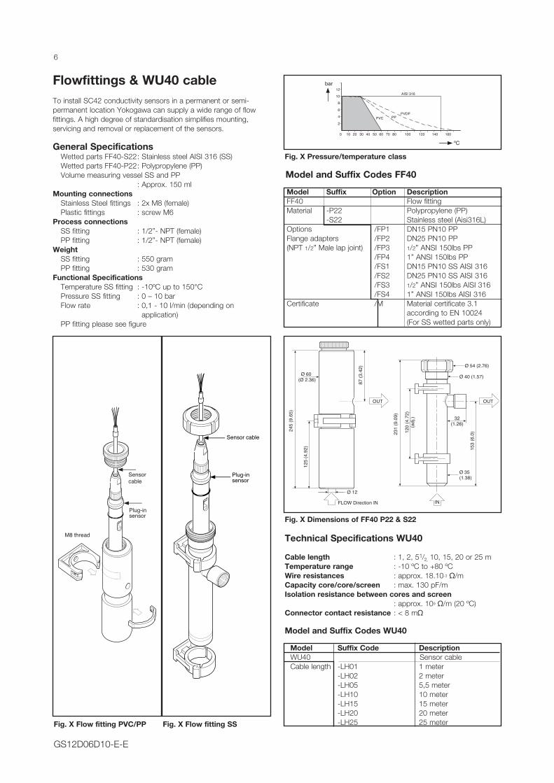
Model Suffix Option DescriptionFF40 Flow fittingMaterial -P22 Polypropylene (PP)
-S22 Stainless steel (Aisi316L)Options /FP1 DN15 PN10 PPFlange adapters /FP2 DN25 PN10 PP(NPT 1/2” Male lap joint) /FP3 1/2” ANSI 150lbs PP
/FP4 1” ANSI 150lbs PP /FS1 DN15 PN10 SS AISI 316 /FS2 DN25 PN10 SS AISI 316 /FS3 1/2” ANSI 150lbs AISI 316 /FS4 1” ANSI 150lbs AISI 316Certificate /M Material certificate 3.1
according to EN 10024 (For SS wetted parts only)
Flowfittings & WU40 cableTo install SC42 conductivity sensors in a permanent or semi-permanent location Yokogawa can supply a wide range of flow fittings. A high degree of standardisation simplifies mounting, servicing and removal or replacement of the sensors.
General Specifications Wetted parts FF40-S22 : Stainless steel AISI 316 (SS) Wetted parts FF40-P22 : Polypropylene (PP) Volume measuring vessel SS and PP : Approx. 150 mlMounting connections Stainless Steel fittings : 2x M8 (female) Plastic fittings : screw M6Process connections SS fitting : 1/2”- NPT (female) PP fitting : 1/2”- NPT (female)Weight SS fitting : 550 gram PP fitting : 530 gramFunctional Specifications Temperature SS fitting : -10ºC up to 150°C Pressure SS fitting : 0 – 10 bar Flow rate : 0,1 - 10 l/min (depending on
application) PP fitting please see figure
0 10 20 30 40 50 60 70 80 100 120 140 160
bar
2
4
6
8
10
12
AISI 316
PVDF
PPPVC
Fig. X Pressure/temperature class
Model and Suffix Codes FF40
Sensor cable
Plug-insensor
Fig. X Flow fitting PVC/PP
Sensor cable
Plug-insensor
M8 thread
Fig. X Flow fitting SS
Technical Specifications WU40
Cable length : 1, 2, 51/2, 10, 15, 20 or 25 mTemperature range : -10 ºC to +80 ºCWire resistances : approx. 18.10-3 Ω/mCapacity core/core/screen : max. 130 pF/mIsolation resistance between cores and screen : approx. 109 Ω/m (20 ºC)Connector contact resistance : < 8 mΩ
Model and Suffix Codes WU40
Model Suffix Code Description WU40 Sensor cable Cable length -LH01 1 meter -LH02 2 meter -LH05 5,5 meter -LH10 10 meter -LH15 15 meter -LH20 20 meter -LH25 25 meter
Ø 35(1.38)
Ø 54 (2.76)
32(1.26)
IN
Ø 40 (1.57)
120
(4.7
2)(a
dj.)
153
(6.0
)231
(9.0
9)
FLOW Direction IN
OUT
245
(9.6
5)
Ø 60(Ø 2.36)
125
(4.9
2)
87 (3
.42)
Ø 12
OUT
Fig. X Dimensions of FF40 P22 & S22

7
GS12D06D10-E-E
375.
41
Bund Top
DCD = ø180
A-A
603
5
6
120º
15
124
3
7
10.84º
13 9 10
11
13
3
5
8
A
A
Fig. X Dimensions of EXAcalxtk calibration tank
Item number Part number Description N Quantity1 st d .131 .10 1 Svøb 12 st d .131 .102 Bund 13 st d .131 .103 Handtag 24 std .131 .104 2” Clamp Ferrule 15 5815010- 6 “Beskrivelse “ 26 std .131 .105 “Beskrivelse “ 17 std .131 .10 6 1½” Clamp Ferrule 18 std .131 .10 7 “Be skrivelse “ 19 std .131 .108 Ben 310 std .131 .109 Fod 31 1 std .131 .1 10 112 std .131 .1 1 1 Beslag 113 std .131 .1 12 “Beskrivelse “ 1
Model Code Suffix Code Option Code DescriptionEXAcalxt R-SC4-5 portable conductivity meter in stainless case with handle -220 90-220V UK plug -110 110V USA versionSensor -1 SC42-SP34 range 0.0 to 400 uS /cm cc: 0.01cm LOW -2 SC42 -EP18 range 500uS to 100 mS/cm cc: 1cm MEDIUM -3 SC42-EP08 range 500usS to 300mS cc: 10 cm H IGHCable c2 WU40-LH02 interconnecting cable c5 WU40-LH05 Interconnecting CableFlow and ProtectiveFitting FF40S22NPT 1/2 NPT steel flow fitting FF40S22TC 1 1/2 inch Triclamp Flow Fitting e lectropolished FF40P Polypro Protective holder onlyTransport Case I-CASE Pelican Transit Case with wheelsCalibration Option K5.6 ACR Full Accredited Calibration of sensor by SRM <0.5% ACCURACY K5.7 COMPARISON Comparison Calibration by reference to other meter <1% ACCURACY K5.5 TEMP 5 point temperature calibration KF5.9 CALONEL enhanced ACCURACY by transmitter calibration
Accessories Suffix Code Option Code DescriptionEXAcalxt-T9-4 9 LITRE EXAcalxt calibration tank Stainless - with 3 process connections Volume: 9 litres Electro polished -220 Power Supply 220 VAC UK plug -110 Power Supply 110 V AC U SA USA plug Pump Centrifugal pump REC−TL−B11,5process connection - standard is 1 TC2 Process connection TRI−Clamp 2”1/2 in ch 2 inch and TC1.5 Process connection TRI−Clamp 1½”21/2 triclamp Ing Process connection Welding socket PF18 DN25 − OPL 40mm pg13.5 Process connection Hamilton Hygienic Socket Sanitært − part no. 242545
Specifications EXAcalxt calibration tank37
5.41
Bund Top
DCD = ø180
A-A
603
5
6
120º
15
124
3
7
10.84º
13 9 10
11
13
3
5
8
A
A
Cables Tubing Calibration Tank Carry case Magnetic Stirers

GS GS12D06D10-E-ESubject to change without notice Printed in The Netherlands, 01-1801 (A) I
YOKOGAWA EUROPE B.V.Euroweg 23825 HD AMERSFOORTThe NetherlandsTel. +31-88-4641 000Fax +31-88-4641 111E-mail: [email protected]/eu
YOKOGAWA CORPORATION OF AMERICA2 Dart RoadNewnan GA 30265United StatesTel. (1)-770-253-7000Fax (1)-770-251-2088www.yokogawa.com/us
YOKOGAWA ELECTRIC ASIA Pte. Ltd.5 Bedok South RoadSingapore 469270SingaporeTel. (65)-241-9933Fax (65)-241-2606www.yokogawa.com/sg
YOKOGAWA HEADQUARTERS9-32, Nakacho 2-chome,MusashinoshiTokyo 180JapanTel. (81)-422-52-5535Fax (81)-422-55-1202www.yokogawa.com
Yokogawa has an extensive sales and distribution network. Please refer to the European website (www.yokogawa.com/eu) to contact your nearest representative.
Every installation and application is different. That means that also for each installation a different type of calibration method is applicable. There are three highly accurate calibration methods :
• In-situ• Replicating the installation• Direct comparison
1. In Situ – Least impact on maintenance• No need to take the sensor out of the process• One point calibration: cell constant is just a single point• Meets calibration requirements • Cell constant 2% with 4:1 TAR (Test Accuracy Ration)• Check transmitter with decade box or precision resistors
2. Replicating the installation – Best option for open type and Inductive conductivity sensors
• Use a Recirculation Tank • Best option for Open type conductivity Sensors and Inductive
conductivity type sensors. The cell constant or installation factor of these sensors are influenced by how and where they are installed.
• It simulates the installation of open sensor as it is in the process.
• Easy Multi point calibration possible by changing the conductivity values in the tank
3. Direct Comparison – Best way to calibrate• Installed in an agitated beaker• preferably 1.5 litres or greater (to stop ambient temperature
effect)• The sensors are stable and seeing the exact same sample• You can increase and decrease values of conductivity in the
container• You can test the sensor across its full operating range• Do not over agitate – to not ripple surface as CO2 can change
sample value
How to perform a Conductivity Calibration
Calibration specifications - all carried out at accredited laboratory
Measurement Measuring Range Uncertainty Standard Refernce Material Value (SRM) MethodTemperature 0.01degC to 90 ºC +/- 0.041 ºC KF 5.5Conductivity - cell constant determination 100 uS/cm 0.34% DFM 100 KF 5.6Conductivity - cell constant determination 1 mS/cm 1000 uS/cm 0.27% DFM 1000 KF 5.6Conductivity - cell constant determination 10mS/cm 0.26% DFM 10000 KF 5.6Conductivity - cell constant determination 100 mS/cm 0.34% DFM 100000 KF 5.6Conductivity - by Comparison 1.300 uS to 99.9 uS/cm 0.96% against reference sensors KF 5.7Conductivity - by Comparison 100.0uS to 239 mS/cm 0.53% against reference sensors KF 5.7