GENERAL SPECIFICATIONS FOR THE CONSTRUCTION OF WATER FACILITIES, SEWERAGE … · 2017-04-20 ·...
88
GENERAL SPECIFICATIONS FOR THE CONSTRUCTION OF WATER FACILITIES, SEWERAGE FACILITIES, STREETS, AND STORM DRAINAGE FACILITIES CITY OF NICHOLASVILLE, KENTUCKY September 25, 1991 Rev. December 2011 Rev. July 2013 Note: These specifications must be used in conjunction with Subdivision Regulations for the City of Nicholasville.
Transcript of GENERAL SPECIFICATIONS FOR THE CONSTRUCTION OF WATER FACILITIES, SEWERAGE … · 2017-04-20 ·...

GENERAL SPECIFICATIONS
FOR THE CONSTRUCTION OF
WATER FACILITIES, SEWERAGE FACILITIES,
STREETS, AND STORM DRAINAGE FACILITIES
CITY OF NICHOLASVILLE, KENTUCKY September 25, 1991
Rev. December 2011 Rev. July 2013
Note: These specifications must be used in conjunction with Subdivision Regulations for the
City of Nicholasville.

TITLE: General Specifications for the Construction of Water Facilities,
Sewerage Facilities, Streets, and Storm Drainage Facilities, City of Nicholasville, Kentucky.
DATE: September 25, 1991 (Rev. December 2011, July, 2013) REGIONAL PLANNING AGENCY: Bluegrass Area Development District STATE PLANNING AGENCY: Kentucky Department for Local Government SOURCE OF COPIES: Nicholasville Planning Commission
City Hall Nicholasville, Kentucky 40356
NO. OF PAGES: 41 ABSTRACT: These specifications represent a revision of the 1980 General
Specifications for the City of Nicholasville, to incorporate changes adopted by the City Commission since that date, and to include revisions recommended by a Technical Review Committee composed of engineers, contractors, attorneys, and businessmen. These specifications are intended to assist not only the Planning Commission and Zoning Enforcement Officer, but also residents of Nicholasville in providing a minimum design standard and a vehicle for assurance of adequate construction of water facilities, sewerage facilities, streets, and storm drainage facilities.

C O N T E N T S SECTION I - WATER FACILITIES Page Number General............................................................................................... 1 Scope.................................................................................................. 1 Distribution Mains............................................................................. 1 Fittings............................................................................................... 3 Gate Valves and Boxes...................................................................... 3 Fire Hydrants...................................................................................... 4 Flushing Hydrants.............................................................................. 5 Services.............................................................................................. 5 Special Connections........................................................................... 8 Testing and Sterilization.................................................................... 8 Erosion and Sedimentation Controls................................................. 11 Approvals........................................................................................... 11 Inspection........................................................................................... 12 Penalties............................................................................................. 12 SECTION II - SEWERAGE FACILITIES General............................................................................................... 13 Scope.................................................................................................. 13 Gravity Sewer Lines........................................................................... 13 Manholes and Appurtenances............................................................ 17 Force Mains and Pump Stations........................................................ 18 Testing Sewers .................................................................................. 19 Sewer Service Line Location............................................................. 21 Erosion and Sedimentation Controls................................................. 23 Approvals........................................................................................... 23 Inspection........................................................................................... 25 Penalties............................................................................................. 26 Waiver and Release............................................................................ 27 SECTION III - STREETS General............................................................................................... 28 Scope.................................................................................................. 28 Streets................................................................................................. 28 Curbs and Gutters............................................................................... 30 Sidewalks........................................................................................... 30 Erosion and Sedimentation Controls.................................................. 30 Approvals........................................................................................... 30 Inspection........................................................................................... 31 Penalties............................................................................................. 31

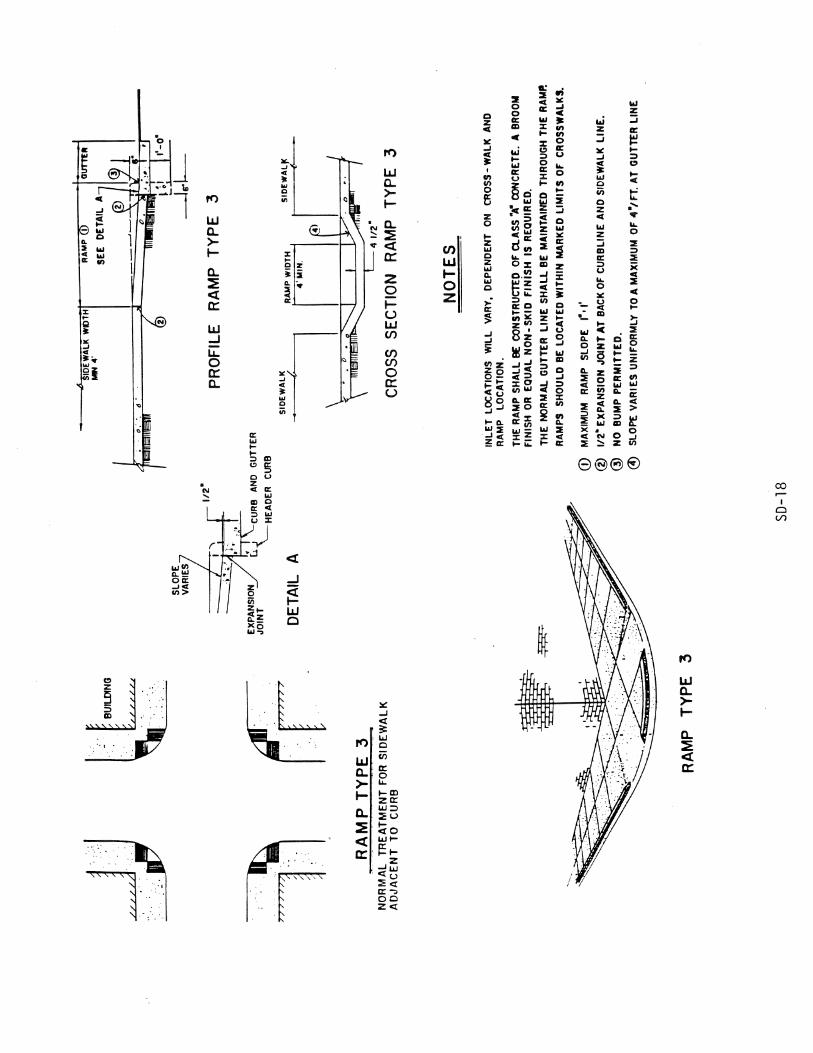
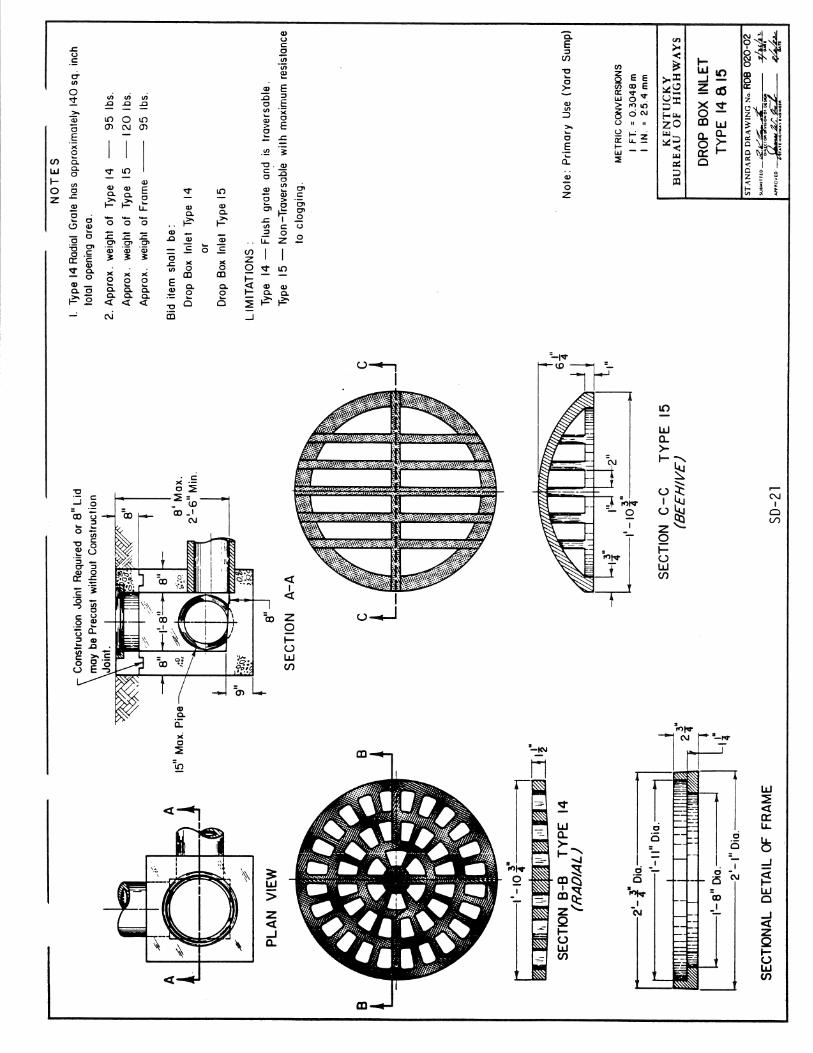
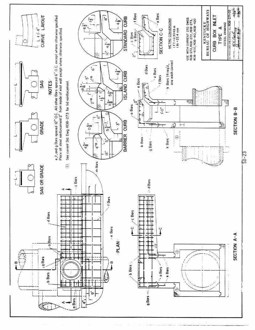
SECTION IV - STORM DRAINAGE FACILITIES General............................................................................................... 32 Scope.................................................................................................. 32 Design Criteria................................................................................... 32 Materials............................................................................................ 37 Installation......................................................................................... 38 Erosion and Sedimentation Controls................................................. 40 Approvals........................................................................................... 40 Inspection........................................................................................... 41 Penalties............................................................................................. 41 STANDARD DRAWINGS Thrust Block Plan & Section............................................................. SD-1 Anchor Blocks................................................................................... SD-2 Typical Gate Valve Setting................................................................ SD-3 Typical Fire Hydrant Installation....................................................... SD-4 Typical Service Connection............................................................... SD-5 Detail of Detector Check Valve ........................................................ SD-6 Detector Check Valve (Double)......................................................... SD-7 Pump Station Anchoring System....................................................... SD-8 Circular Manhole............................................................................... SD-9 Drop Manhole.................................................................................... SD-10 House Connection for Shallow Sewer............................................... SD-11 House Connection for Deep Sewer.................................................... SD-12 Standard Concrete Piers-Pipe Supports.............................................. SD-13 Bituminous Pavement Joints.............................................................. SD-14 Pavement Replacement...................................................................... SD-15 Standard Box Curb & Gutter............................................................. SD-16 Handicap Ramp (Type 1 & Type 2)................................................... SD-17 Handicap Ramp (Type 3)................................................................... SD-18 Drop Box Inlet Type 11..................................................................... SD-19 Drop Box Inlet Type 12 or 12 A........................................................ SD-20 Drop Box Inlet Type 14 & 15............................................................ SD-21 Curb Box Inlet Type A (Detail Drawing)........................................... SD-22 Curb Box Inlet Type A (Steel Drawing)............................................ SD-23 Curb Box Inlet Type A (Top Phase Tables)....................................... SD-24 Curb Box Inlet Type A (Detail & Bar Chart for 8" Lid).................... SD-25 Standard Curb Box Inlet Type F........................................................ SD-26 Sloped & Flared Headwalls for 12" to 27" Pipe................................ SD-27 Pipe Culvert Headwalls 0� Skew.......................................................... SD-28 Dimensions and Quantities 30" - 108" Headwalls Circular Pipe 0� Skew......................................................................... SD-29 Bill of Reinforcement 30" to 90" Diameter Circular Pipe Headwalls 0� Skew....................................................... SD-30

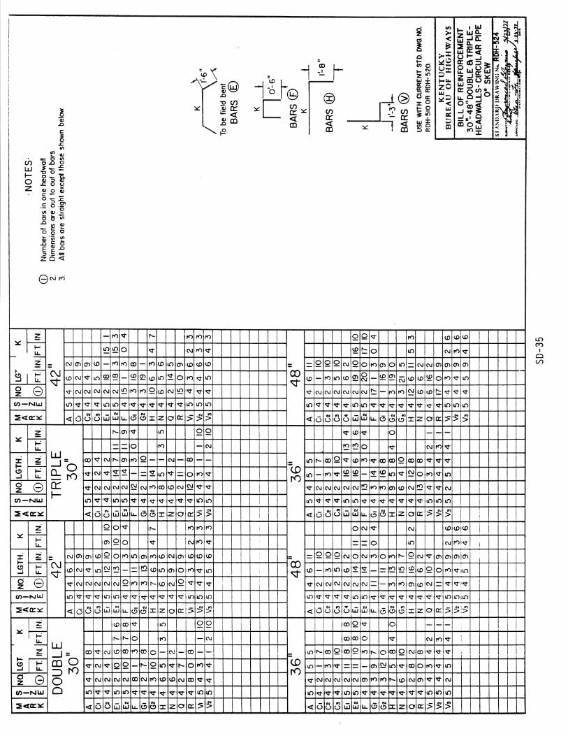
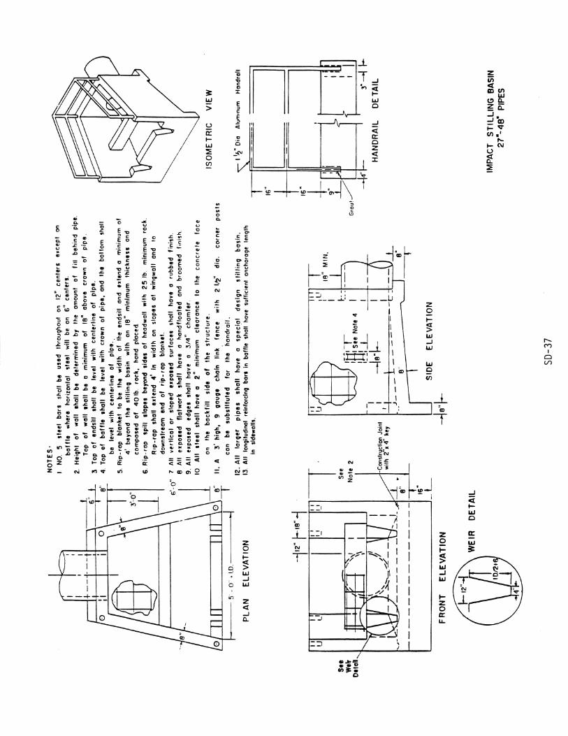
Bill of Reinforcement 96" to 108" Diameter Circular Pipe Headwalls 0� Skew....................................................... SD-31 Double Pipe Culvert Headwalls 0� Skew............................................. SD-32 Triple Pipe Culvert Headwalls 0� Skew............................................... SD-33 Dimension & Quantities 30" - 48" Double & Triple Headwalls - Circular Pipe 0� Skew.......................................... SD-34 Bill of Reinforcement 30" - 48" Double & Triple Headwalls - Circular Pipe 0� Skew.......................................... SD-35 Impact Stilling Basin 12" - 24" Pipes.................................................... SD-36 Impact Stilling Basin 27" - 48" Pipes.................................................... SD-37 Low Flow Concrete Channel................................................................. SD-38 Silt Checks............................................................................................. SD-39 Temporary Silt Fence............................................................................. SD-40 Silt Trap Type A & B............................................................................. SD-41 Street Sign Installation Requirements.................................................... SD-42

1
SECTION I
WATER FACILITIES
Section I-1. GENERAL Specifications given hereafter outline the minimum standards for materials, installation methods, testing procedures, and inspections required by the City of Nicholasville for the construction of water distribution mains, customer services, and other appurtenances necessary to provide adequate fire protection and maintenance operations.
Section I-2. SCOPE The scope of these specifications is to set forth the policies of the City of Nicholasville regarding construction of potable water related facilities. Design of the facilities covered herein must be performed by and carry the seal and signature of a qualified registered Professional Engineer.
Section I-3. DISTRIBUTION MAINS (1) Definition - Distribution mains are those pipes 6 inches and larger in size used to transport
large volummes of potable water to small areas. (2) Design - This section is given to set forth minimum design standards for water distribution
mains. These are the minimum requirements acceptable to the City of Nicholasville, but are not given as a substitute for design by a qualified Professional Engineer.
(a) Pipe Sizes - Distribution mains shall be designed in accordance with all requirements of
the Commonwealth of Kentucky Department for Environmental Protection, Division of Water. Pipes for domestic flow only shall be sized to provide a minimum residual pressure of 30 pounds per square inch (psi) at any meter considering a peak flow condition of 2 gallons per minute (gpm) draw off occurring simultaneously at each meter. In addition, the pipe shall be large enough to provide 1,000 gpm fire flow with 20 psi residual pressure from any fire hydrant. All distribution mains that are more than 500 feet long shall be looped to eliminate dead-end lines. Distribution mains that are looped and distribution mains that are designed for future extension shall be 8 inches or larger in size. A fire hydrant or a flushing hydrant (minimum 2-1/2 inch diameter outlet) shall be provided at the end of dead-end lines for flushing purposes. The City of Nicholasville shall provide the Design Engineer with flow and pressure data at a fire hydrant near each proposed connection to the City's water main. The Design Engineer shall provide the City with design data showing that the requirements listed herein have been met.
(b) Valving - Gate valves of the same size as the distribution main shall be installed in the
lines at each intersection and in such a manner that only the customers on one street between intersections will be without service whenever line repair or servicing is required. Additional valves shall be installed such that the distance between gate valves on distribution mains shall not exceed 1,000 feet.

2
(3) Materials - Water distribution mains may be constructed only of the following materials and
to the specifications given hereafter:
(a) Ductile Iron Pressure Pipe - Ductile Iron Pipe shall be centrifugally cast iron pipe with rubber "Push Joints". Pipe and fittings shall be designed in accordance with American Waterworks Association Standards A-21.1, C151 and C110. Pipe shall be full "enamelined" and given a bituminous coating. Pipe shall be Fastite, Boltite, or Tyton.
(b) PVC Pressure Pipe - PVC plastic pressure pipe shall be PVC 1120 manufactured of Class
12454-A or Class 12454-B resin material with a hydrostatic-design-basis (HDB) rating of 4,000 psi at 73.4 degrees F (23 degrees C). PVC pipe must be NSF approved and bear the NSF seal. The pipe shall be designed, manufactured, and tested in conformance to the latest revision of the American Waterworks Association designation AWWA C900 and each length of pipe shall be so labeled. Each length of pipe shall be furnished and labeled to show that the outside diameter (O.D.) is equal to that for ductile iron and cast iron pipe. The pipe shall have a standard dimensional ratio (SDR) of 18 and 14 for Class 150 and 200 respectively. Pipe joints shall be rubber gasket push-on joints either constructed integrally with the pipe or as a separate coupling constructed of the same material and to the same pressure specifications as the pipe. SDR 14 Class 200 pipe shall be used if the static and/or working pressure is expected to exceed 100 pounds per square inch (psi).
(Adopted: 07-18-02 Ordinance 418-2002) (4) Installation - All water lines shall be installed so as to have a minimum cover of 30 inches
above the top of the pipe. Distribution mains shall be laid at least 10 feet horizontally from any existing or proposed sewer. The distance shall be measured edge to edge. In cases where it is not practical to maintain a 10 foot separation, the distribution main may be laid on an undisturbed shelf located on one side of the sewer at such an elevation that the bottom of the water main is at least 18 inches above the top of the sewer. This deviation will not be allowed for force mains. Distribution mains crossing sewers shall be laid to provide a minimum vertical distance of 18 inches between the outside of the water main and the outside of the sewer. At crossings, one full length of water pipe shall be located so both joints will be as far from the sewer as possible. Special structural support for the water and sewer pipes may be required. No connections shall be made to the City's water distribution system until the City specifically authorizes the connections.
(a) Trenching - The walls of all excavations shall be vertical from the bottom of the
excavation to a minimum of 1 foot above the top of the pipe. If necessary, the trench walls may be sloped from a point 1 foot above the pipe to the original ground line. Trench width at the top of the pipe shall not be less than 1 foot plus the outside diameter of the pipe, and shall not be greater than 2 feet plus the outside diameter of the pipe.
(b) Bedding and Backfill - When the trench excavation is in rock, the pipe shall be bedded on
at least 6 inches of No. 9 or No. 11 crushed stone, and shall be backfilled with No. 9 or No. 11 crushed stone for a minimum of 12 inches above the top of the pipe. Backfill above this cushion shall not contain pieces of rock larger than 12 inches in any

3
dimension. When the trench excavation is in soil, and not within a street, the pipe can be bedded and backfilled with select soil containing no pieces of rock larger 3/4 inch in any dimension. When the trench excavation is within a street (i.e. back of curb to back of curb), then the entire trench shall be backfilled with No. 9 or No. 68 crushed stone.
(c) Detectable Marking Tape - A continuous, detectable underground metalized mylar water
line marking tape shall be placed directly above all water mains, 12 to 18 inches below finished grade, prior to final backfill of the trench. The marking tape shall be 2 inches wide minimum, blue in color, and shall bear a continuous printed inscription stating "CAUTION WATER LINE BURIED BELOW". The tape shall have integral wires, foil backing, or other means to enable detection by a metal detector when the tape is buried up to 3 feet deep. The metallic core shall be encased in a protective jacket or provided with other means to protect it from corrosion. Detectable marking tape shall be as manufactured by Lineguard, Inc., Wheaton, IL 60187, or equal.
(Adopted: 04-12-2001 Ordinance 364-2001)
Section I-4. FITTINGS Fittings are defined as those items which are installed in a pipeline to change direction and include all bends, tees, crosses, and wyes necessary to provide a smooth transition from one direction to another. (1) Materials - Fittings used in the construction of distribution mains shall be bituminous coated
ductile iron mechanical joint and shall be fully cement mortar lined. (2) Thrust Blocks - Thrust blocks shall be constructed at each fitting to adequately resist the
thrust developed at each fitting. Each block shall be constructed of portland cement concrete with a compressive strength of not less than 3,000 psi at 27 days. No block shall be constructed to dimensions less than those given on the STANDARD DRAWINGS when the bearing surface is original undisturbed solid material. Whenever adequate bearing surfaces are not available, then the dimensions of the block must be increased to adequately resist the maximum thrust.
Section I-5. GATE VALVES AND BOXES (1) VALVES - All gate valves shall be AWWA, Class C valves or Resilient Seat valves and
designed for a minimum water working pressure of not less than 200 psi and shall be given a shop test to successfully withstand a hydrostatic test of 300 psi. AWWA gate valves shall be iron body, fully bronze-mounted, double disc, parallel seated, with bell ends so as to be directly connected to pipe with rubber ring joints. Resilient Seat gate valves shall be iron body with bell ends so as to be directly connected to pipe with rubber ring joints, and shall meet all applicable AWWA standards. Valves shall open counter-clockwise. Valves shall have the interior thoroughly cleaned and shall be inspected in both the opened and closed positions just prior to installation. Valves shall be as manufactured by Mueller Co., Decatur, Ill., M&H Valve Company, Anniston, Alabama, or equal as approved by the City or their authorized representative.

4
(2) VALVE BOXES - All valves in paved areas shall have adjustable two-piece cast iron valve
boxes and covers suitable for 24 to 36 inch pipe cover. Valves located outside paved areas may have 6 inch diameter PVC boxes with cast iron or aluminum castings specifically designed to be fastened to the top of the PVC for the covers. Covers shall be cast iron and stamped "WATER". The tops of valve boxes located outside paved areas shall be set at finish grade in a minimum 18 inch square concrete slab. All aluminum surfaces that will be in contact with concrete shall receive a bitumastic coating prior to placing the concrete. Earth shall be thoroughly tamped under the concrete slab. Valve boxes, castings, and lids shall be as manufactured by Tyler Pipe, Tyler, Texas, or equal as approved by the City or their authorized representative.
Section I-6. FIRE HYDRANTS Fire hydrants within the Nicholasville city limits shall be located on lines 6 inches or larger in size, and shall meet the minimum flow and pressure requirements of 1,000 gpm at 20 psi residual pressure. Fire hydrants shall be installed at all street intersections, and at other places as necessary to provide a spacing not to exceed 500 feet between the hydrants as measured along public right-of-way. Additional fire hydrants shall be installed in multi-family residential, commercial, and industrial areas so that buildings are not located more than 250 feet from a hydrant, and so that buildings requiring a sprinkler system are not located more than 150 feet from a hydrant. Fire hydrants shall be installed on the opposite side of the street from the water main as shown on the STANDARD DRAWINGS, unless stainless steel rodding, or mechanical joint anchor fittings are used to restrain the hydrant and valve to the water main. Upon installation, and prior to acceptance by the City of Nicholasville for operation and maintenance, each fire hydrant shall be flow tested and certified by a licensed professional engineer to meet the minimum flow and pressure requirements. Fire hydrants outside the Nicholasville city limits shall be located on lines 6 inches or larger in size, and shall meet the minimum flow and pressure requirements of 250 gpm at 20 psi residual pressure. If the minimum flow and pressure requirements can be met, fire hydrants shall be installed at all street intersections, and at other places as necessary to provide a spacing not to exceed 500 feet between the hydrants as measured along public right-of-way. Additional fire hydrants shall be installed outside of public right-of-way in other places requested by the City of Nicholasville. Fire hydrants shall be installed on the opposite side of the street from the water main as shown on the STANDARD DRAWINGS, unless stainless steel rodding, or mechanical joint anchor fittings are used to restrain the hydrant and valve to the water main. Upon installation, and prior to acceptance by the City of Nicholasville for operation and maintenance, each fire hydrant shall be flow tested and certified by a licensed professional engineer to meet the minimum flow and pressure requirements. All fire hydrants shall be of the compression type, with cast iron body, fully bronze-mounted, have a mechanical joint 6" shoe, suitable for a working pressure of 200 psi and shall be in accordance with the latest specifications of the AWWA. Hydrants located within the Nicholasville city limits shall have two pumper nozzles, and hydrants located outside the Nicholasville city limits shall have two hose nozzles.

5
Fire hydrants shall be constructed in a manner permitting withdrawal of internal working parts without disturbing barrel of casing. Hydrants shall be provided with sliding frost cases or a porous fill around barrel. Valve, when shut, shall be reasonably tight if upper portion of barrel should be broken off. Valve opening shall be at least 5-1/4 inches in diameter. There shall be no chattering under any conditions of operation. Each hydrant shall be shop tested to a hydrostatic pressure of 300 psi with valve in both opened and closed position. Hydrants shall open counter clockwise. The direction of opening shall be cast in the head of the hydrant. Hydrants shall be painted with one coat of red lead and two finishing coats of Hydrant Enamel, fire department red, in color. Fire hydrants shall have bell ends for receiving rubber rings for direct joining to pipe and shall be as manufactured by Mueller Co., Decatur, Illinois, Super Centurion 200, 2-way catalog number A-425 for hydrants located within the Nicholasville city limits and Super Centurion 200, 2-way catalog number A-422 for hydrants located outside the Nicholasville city limits. (Adopted: 04-12-07 Ordinance 645-2007)
Section I-7. FLUSHING HYDRANTS
Flushing hydrants shall be installed at the end of dead-end distribution mains unless fire hydrants are installed for flushing purposes. Flushing hydrants shall be of automatic freeze-proof design with weep hole installed within a 2 inch ball valve. The valve shall be 600 lb. wog bronze body with chrome plated brass ball and teflon seals. The hydrant barrel shall be black iron pipe. The exterior shall receive a 4 mil thickness of electrostatically applied acrylic enamel. The overall length of the hydrant will vary, according to the depths of the water line. A brass hose connection, 2-1/2 inch NSFT with attached cap and chain, shall be provided for convenience in flushing. The operating device shall be of key type design with permanent attachment to the valve stem. The valve stem shall be full length of the hydrant barrel with permanent attachment to the valve. The hydrants shall have provision for lock up to prevent tampering. Flushing hydrants shall be Aquarius One-O-One "Hidden Hydrant" as manufactured by Gil Industries, Inc., Pensacola, Florida, or equal as approved by the City or their authorized representative.
Section I-8. SERVICES This part of these specifications includes all necessary construction and supplies required to bring the water from the distribution main to the customers side of the meter. Services shall include the service saddle, corporation stop, copper pipe service line, meter yoke, and meter vault.
6
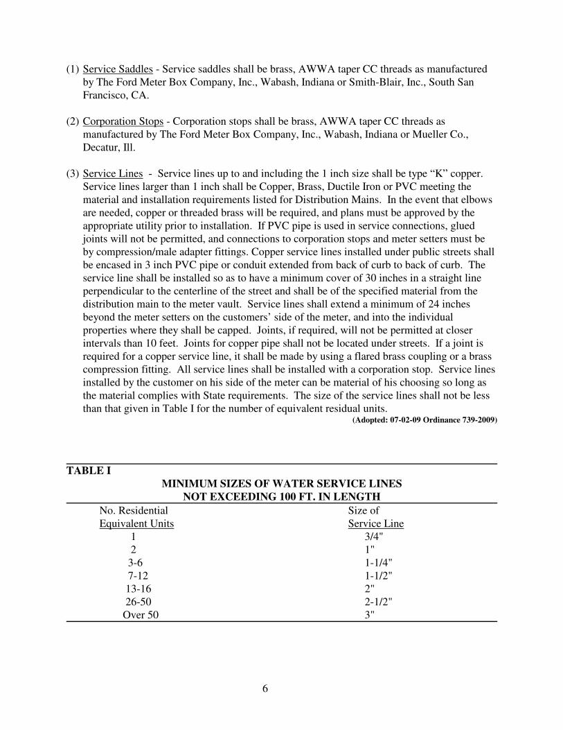
(1) Service Saddles - Service saddles shall be brass, AWWA taper CC threads as manufactured by The Ford Meter Box Company, Inc., Wabash, Indiana or Smith-Blair, Inc., South San Francisco, CA.
(2) Corporation Stops - Corporation stops shall be brass, AWWA taper CC threads as
manufactured by The Ford Meter Box Company, Inc., Wabash, Indiana or Mueller Co., Decatur, Ill.
(3) Service Lines - Service lines up to and including the 1 inch size shall be type “K” copper.
Service lines larger than 1 inch shall be Copper, Brass, Ductile Iron or PVC meeting the material and installation requirements listed for Distribution Mains. In the event that elbows are needed, copper or threaded brass will be required, and plans must be approved by the appropriate utility prior to installation. If PVC pipe is used in service connections, glued joints will not be permitted, and connections to corporation stops and meter setters must be by compression/male adapter fittings. Copper service lines installed under public streets shall be encased in 3 inch PVC pipe or conduit extended from back of curb to back of curb. The service line shall be installed so as to have a minimum cover of 30 inches in a straight line perpendicular to the centerline of the street and shall be of the specified material from the distribution main to the meter vault. Service lines shall extend a minimum of 24 inches beyond the meter setters on the customers’ side of the meter, and into the individual properties where they shall be capped. Joints, if required, will not be permitted at closer intervals than 10 feet. Joints for copper pipe shall not be located under streets. If a joint is required for a copper service line, it shall be made by using a flared brass coupling or a brass compression fitting. All service lines shall be installed with a corporation stop. Service lines installed by the customer on his side of the meter can be material of his choosing so long as the material complies with State requirements. The size of the service lines shall not be less than that given in Table I for the number of equivalent residual units.
(Adopted: 07-02-09 Ordinance 739-2009)
TABLE I
MINIMUM SIZES OF WATER SERVICE LINES
NOT EXCEEDING 100 FT. IN LENGTH No. Residential Size of Equivalent Units Service Line
1 3/4" 2 1" 3-6 1-1/4"
7-12 1-1/2" 13-16 2" 26-50 2-1/2" Over 50 3"

7
(4) Meter Setters - Meter Setters for 3/4" services shall be AWWA 5/8" X 3/4" with brace eye, cutoff, check valve at the meter outlet, and all-purpose fittings (brass). Meter setters for 1" services shall have brace eyes, cutoff, check valve at the meter outlet, and all-purpose fittings (brass). Meter setters for 1-1/2" and 2" services shall be for 1-1/2" and 2" flanged meters and shall have brace eyes, key valve inlets, angle check valve outlets, bypass, and female iron pipe inlets and outlets. It shall be necessary to contact the appropriate utility for the type of meter setter to be used for services larger than 2". All meter setters shall be as manufactured by the Ford Meter Box Company, Inc., Wabash, Indiana or Mueller Co., Decatur, Ill. The riser height shall be sufficient to place the meter within 24 inches of the meter vault lid.
(5) Meter Vaults
(a) Boxes - The boxes for meter vaults shall be polyethylene with an inside diameter of 18 inches for 3/4" single services, 24 inches for 1" and duplex services, 30 inches for 1-1/2" services, and 36 inches for 2" services. It shall be necessary to contact the appropriate utility for the type of meter vault to be used for services larger than 2". Extension rings shall be required for all boxes larger than 18 inches in diameter.
(b) Cover and Lid - The cover and lid shall be cast iron with standard pentagon bolt as
manufactured by the Ford Meter Box Company, Inc., Wabash, Indiana, Catalog No. C32 or equal if located outside of the City of Nicholasville service territory; Catalog No. C32-T with one 1-3/4" hole for single 3/4" services within the City of Nicholasville service territory; and Catalog No. C32-TT with two 1-3/4" holes for double meter settings within the City of Nicholasville service territory. Cast iron flat top covers and lids shall be, used only at locations specifically approved by the City of Nicholasville for replacements of existing covers and lids and shall be as manufactured by Vestal MFG, Sweetwater, Tennessee.
(6) Location of Meter Vaults
(a) Residential - Water service lines and meter vaults shall be installed at the approximate mid-point of each front property line at finish grade utilizing a single meter setting for single family dwellings and a double meter setting for duplexes for lots with street frontages greater than 50 feet. Double meter settings may be installed on common side lot lines for townhouses if the location complies with the approved Development Plan lots with street frontages of 50 feet or less.
(b) Commercial and Industrial - It shall be necessary to contact the appropriate utility for the
location of meter vaults and water service lines on commercial and industrial lots.
(c) Meter vaults shall be installed a minimum of 4 feet horizontally from the distribution main but shall not extend more than 20 feet beyond the street right-of-way. They shall not be located and/or installed in parking lots, driveways or sidewalks.
(Adopted: 03-30-00 Ordinance 330-2000)

8
Section I-9. SPECIAL CONNECTIONS This section of these specifications outlines the policies of the City of Nicholasville, Kentucky, in regard to special connections. (1) Fire Protection Service - When it is necessary for any customer to have full line flow for fire
protection purposes, there shall be installed in the line a device known as a "Detector Check Valve" with a metered by-pass. A detailed drawing of the Detector Check Valve Vault shall be submitted to the City for review and approval prior to installation. The metered by-pass shall be of sufficient size to carry normal usage without activating the "Detector Check Valve". The Detector Check Valve shall be as manufactured by the Kennedy Valve Manufacturing Company Figure Number 1371 Model Number B-2 or equal as approved by the City. Owners that install or upgrade fire suppression systems that require a fire department connection (FDC) shall install a 5 inch “Storz”(tm) fitting with cover attached to a 30 degree down turn on the fire departments connection outlet fitting. The distance from the ground to the bottom edge of the fitting shall be no less than 24 inches or no more than 30 inches. All FDC's shall be located at least 15 feet away from the structure, unless the installation of a new sprinkler system or substantial upgrade of a sprinkler system is in an existing building and a remote FDC away from the building is not possible. The FDC shall not be obstructed in any way that would hinder access or operation from a fire department apparatus. If the FDC is in an un-curbed vehicle accessible area, it shall be protected by brightly colored traffic bollards engineered to protect it from vehicular traffic. The owner and/or operator during renovation or new installation shall install or upgrade the system to include Double Check Valves installed within the sprinkler pit after the Post Indicator Valve (PIV) line. All PIV installations or upgrades shall be electronically monitored and painted bright red with the indicator sight glass facing the roadway and/or FDC. All FDC and PIV installations shall have a marker affixed on or near the device that clearly indicates the property or area that the device serves. A fire hydrant meeting City of Nicholasville specifications shall be installed or located within 50 feet of the FDC and shall be located within 10 feet of a paved surface roadway capable of access by and of supporting a fire apparatus. (Adopted: 09-20-07 Ordinance 674-2007)
(2) Other Special Connections - All other requests for special connections shall be made to the
City in writing explaining the type of connection and the purpose for which it will be used. The City will then consult its engineer for recommendations regarding the requested special connection.
Section I-10. TESTING AND STERILIZATION This section includes the minimum requirements for testing and sterilization of the completed project. The Developer and/or Contractor shall notify the City at least two hours prior to any testing. The water distribution systems shall not be placed into service until written test results for all tests are furnished to the City of Nicholasville.

9
(1) Testing - All lines shall be laid, joints completed, fittings and valves installed, service lines and meter yokes installed and the system backfilled prior to testing. Each section of the system shall be subjected to a pressure of not less than 150 psi for Class 150 pipe and 200 psi for Class 200 pipe. The entire section shall be subjected to and maintained at the pressures indicated above for a period of 24 hours. Allowable leakage for any section shall be calculated in proportion to the amounts of each length of pipe used within the section being tested. Should any test of sections of pipe line disclose leakage per mile greater than the specified limit, the defective part or parts shall be located and repaired until leakage is within specified limits. No section will be accepted until leakage, when tested as indicated above, meets the following requirements of Table II.
TABLE II
ALLOWABLE LEAKAGE Allowable Leakage
Length of Per 24 Hours Per Inch Nominal Pipe Pipe Diameter Per Mile
3' - 3" 25 gallons 6' - 6" 20 gallons 10' 15 gallons 13' 15 gallons 16' 13 gallons 18' 13 gallons 20' 12 gallons
(2) Sterilization - All extensions to existing water distribution systems shall be thoroughly
disinfected before being placed into service, by the use of chlorine or chlorine compounds in such amounts as to produce a concentration of at least 50 ppm and a residual of at least 25 ppm at the end of 24 hours and followed by a thorough flushing. Samples shall be taken at the beginning and end of the 24 hour period, and certified test results including sample locations shall be furnished to the City of Nicholasville. Table III (See Page 12) gives the theoretical amount of HTH to produce 50 ppm of chlorine in pipe.
(3) Bacteriological Tests - Bacteriological samples shall be taken by a certified tester and shall be
submitted for each extension to existing water distribution system after disinfection and flushing. A core zone which includes up to the first 1/2 mile shall be established. Two samples shall be taken from the core zone. Additionally, one sample per mile for each mile of new distribution line shall be taken. New water distribution lines shall not be placed into service until the proper number of representative bacteriological samples taken at the specified points are examined and are shown to be negative. Each sample shall include the sample location, and notification of the analytical results shall be furnished to the City of Nicholasville.

10
TABLE III
AMOUNT OF HTH REQUIRED TO PRODUCE 50 PARTS PER MILLION OF CHLORINE IN PIPE
CHLORINE IN PIPE
Normal Pipe Size
Contents in 100 Ft. Section
Amount of HTH required per 100 ft. length to give 50 ppm available chlorine
Length of pipe in which one ounce of HTH will produce 50 ppm available C12
Cu. Ft.
Lbs.
Gals.
Ounces (approx.)
Pounds
Tablespoons Level
4
8.75
545
65.5
5/8
0.039
2
168.0
6
19.65
1,225
147.0
1-3/8
0.087
4
71.9
8
34.90
2,180
261.0
2-1/2
0.159
7-1/3
39.4
10
54.55
3,405
408.0
3-7/8
0.244
11-1/3
25.6
12
78.55
4,905
587.0
5-5/8
0.350
16-1/3
17.9

11
Section I-11. EROSION AND SEDIMENTATION CONTROLS Temporary erosion and sedimentation controls shall be erected and maintained for all disturbed and/or regraded areas during construction, and until final controls become effective. Erosion and sedimentation controls shall be detailed on the Construction Plans. (1) Erosion Control - Erosion controls include, but are not limited to, interceptor ditches,
seeding, mulching, watering, and reseeding on all disturbed surfaces including regraded areas, borrow areas, stockpiles, and waste areas. Areas disturbed on the construction site which will not be redisturbed within a 60 day period, shall be seeded to produce a temporary cover of grass. Fertilizer (10-10-10, or equivalent) shall be broadcast uniformly on the areas to be seeded at a rate of 400 pounds per acre. The mixture of seeding shall be 30 pounds of tall fescue and 20 pounds of ryegrass per acre. Seed shall be broadcast evenly over the areas to be seeded, and cultipacked or otherwise pressed into the soil. Seed and fertilizer may be mixed together and applied after the soil has been prepared. After the seed has been sown, the areas so seeded shall be mulched with straw at a rate of approximately one bale per 2,000 square feet (approximately 1 inch loose depth).
(2) Sedimentation Control - Sedimentation controls include, but are not limited to, silt fences,
staked straw bales, silt dams, and silt traps. Silt control measures shall be used to prevent off-site siltation, and silt shall be removed periodically as required.
Section I-12. APPROVALS This section provides information related to the various approvals that are required prior to start of construction and prior to acceptance by the City of Nicholasville of the completed project. (1) State Approval - Four sets of plans carrying the seal and signature of a registered Professional
Engineer for the proposed construction, along with a copy of a letter from the City of Nicholasville, or appropriate utility, stating that the project is being reviewed and water will be supplied, must be submitted to the Commonwealth of Kentucky Department for Environmental Protection, Division of Water, for their review and approval. No construction shall take place prior to approval from the Commonwealth of Kentucky. Upon completion of the construction, the City shall certify to the Department for Environmental Protection, Division of Water that the water supply facilities were constructed and tested in accordance with the approved plans, specifications, and stipulations listed in the Division of Water approval letter.
(2) Planning Commission Approval - Two sets of the water distribution plans shall be submitted
to the Planning Commission Staff Office for review. The Planning Commission's review will be to verify that the project complies with the requirements of the Nicholasville Subdivision Regulations and General Specifications, and that the proposed construction integrates satisfactorily into the City's distribution system. After the review, eight sets of the plans shall be submitted for written approval. At least one set shall contain the original seal and signature of a registered Professional Engineer on each sheet. Prior to the Planning Commission's approval of the Construction Plans for the water distribution system, the

12
Developer shall make available to the City a copy of the approval letter from the Commonwealth of Kentucky. Construction shall not begin until the Planning Commission has issued written approval of the plans. Upon completion of the construction, the Developer shall make a written request to the Planning Commission Staff Office for a detailed inspection by the City for acceptance of the public facilities.
(3) Changes - The Developer's Engineer may make minor changes to the approved plans if
written notification of the changes is given to the Planning Commission Staff Office, if such changes meet the requirements of the Nicholasville Subdivision Regulations and General Specifications, and if the changes do not violate any City or State regulation. Any changes from the approved plans that are not in compliance with the regulations must be approved by the Commonwealth of Kentucky Department for Environmental Protection, Division of Water, and by the Planning Commission prior to making the proposed changes.
(4) As-built Drawings - After the completion of the construction, the Developer shall submit six
sets of prints and one set of reproducible mylars to the City for the As-Built System. The As-Built Drawings shall consist of the Construction Plans with notations of changes shown.
Section I-13. INSPECTION All water system construction shall be inspected by the City's authorized representative before covering to insure that the construction progresses in compliance with the approved plans and specifications; however, small area spot coverings of the water line prior to inspection are acceptable to prevent flotation. The City's authorized representative shall have the right to require any part of the water system covered prior to inspection, to be uncovered prior to approval. The Developer and/or Contractor shall provide ready access to the construction site for inspection by City representatives throughout the construction period. If a City representative determines that the construction is not in compliance with the approved plans or specifications, he shall notify the Contractor and the Developer. The City's authorized representative shall have the right to stop the construction until the deficiencies are corrected.
Section I-14. PENALTIES Failure to construct the improvements in accordance with approved plans and specifications, and the regulations contained herein (including violations of conditions or safeguards established in connection with approval) shall constitute a misdemeanor. Any person who so violates these requirements shall upon conviction thereof be fined not less than one hundred dollars ($100.00) but not more than five hundred dollars ($500.00) for each conviction. Each day of violation shall constitute a separate offense. The Owner or Developer of any subdivision and any engineer, contractor, builder, agent, employees or other person who commits, participates in, assists in, or maintains such violation may each be found guilty of a separate offense and suffer the penalties herein provided. Nothing herein contained shall prevent the City from taking such other lawful action as is necessary to prevent or remedy any violation.

13
SECTION II
SEWERAGE FACILITIES
Section II-1. GENERAL Specifications given hereafter outline the minimum standards for materials, installation methods, testing procedures, and inspections required by the City of Nicholasville for the construction of sewerage facilities.
Section II-2. SCOPE The scope of these specifications is to set forth the policies of the City of Nicholasville regarding construction of sewerage facilities. Design of the facilities covered herein must be performed by and carry the seal and signature of a qualified registered Professional Engineer.
Section II-3. GRAVITY SEWER LINES (1) Description - Gravity sewer lines are defined as those lines which carry sewage under a
driving force provided only by the slope of the sewer line. (2) Design - This section is given to set forth minimum design standards for gravity sewer lines.
These are the minimum requirements acceptable to the City of Nicholasville, but are not given as a substitute for design by a qualified Professional Engineer.
(a) Pipe Sizes - Pipes shall be sized to flow full at maximum estimated peak flow (3 times
the average daily flow) for all sections of pipe 12 inches in diameter and less. For pipes larger than 12 inches in diameter, sizes shall be chosen such that the pipe will flow 2/3 full at estimated peak flow conditions (3 times the average daily flow). Refer to Table IV for Estimated Wastewater Flows (See Page 17). Pipe diameters shall be not less than 8 inches for any collector or interceptor line.
(b) Slopes - Pipe slopes shall not be less than those given in Table V (See Page 18).

14
TABLE IV
ESTIMATED WASTEWATER FLOWS ZONING EQUIVALENT POPULATION AVERAGE AVERAGE DISTRICT PER ACRE GAL/ACRE/DAY GAL/UNIT/DAY A-1* - - -
R-1 14 1,400 350
R-1A 3 300 350
R-1B 6 600 350
R-1C 8 800 350
R-1D 14 1,400 350
R-1E 17 1,700 350
R-1F 25 2,500 350
R-1T & R-3T 50 5,000 350
R-2 Single 17 1,700 350
R-2 Duplex 28 2,800 350
R-3 Duplex 28 3,400 350
R-3 Apartment 70 7,000 300
P-1 20 2,000 -
DB 20 2,000 -
B-1 20 2,000 -
B-2 20 2,000 -
B-3 20 2,000 -
I-1 ** 36 3,600 -
I-2 ** 36 3,600 -
FP *** - - -
H-1 *** - - - FUTURE LAND
USE MAP Residential
Low Density 14 1,400 -
High Density 55 5,500 -
Commercial 20 2,000 -
Industrial ** 36 3,600 -
Public/Semi-Public *** - - -
Agriculture 3 300 -
* Flows shall be based on the proposed land use as shown in the Nicholasville Comprehensive
Plan. ** Flows may be adjusted by the City if a major industrial user is anticipated. ***Flows are site specific and will be determined by the City on case by case basis.

15
TABLE V
MINIMUM ALLOWABLE SLOPES Pipe Size Minimum Slope Per 100 Feet
4" 1.00 6" 0.60 8" 0.40 10" 0.28 12" 0.22 15" 0.17 18" 0.14 21" 0.12 24" 0.10 27" 0.08 30" 0.067 36" 0.058
(c) Service Laterals - Service laterals shall be of the same material as the main line, shall
have a minimum length of 3 feet from a tee placed at an angle no steeper than 45 degrees, and shall extend into the individual properties where they shall be terminated, as indicated on the STANDARD DRAWINGS. Termination for any 8 inch service line shall be at a manhole located on private property. Each lot shall be served by a separate lateral connected to the sewer main except for lots located in R-1T or R-3T zones which may have two (2) attached units served by a lateral located on the common side lot line. Pipe diameters for service lines shall be not less than those given in Table VI.
TABLE VI
SEWER SERVICE LINE SIZE
Unit Sewer Service Line Size Single Family Residential 4" * Duplexes through 8 unit apartments 6" More than 8 unit apartments 8" minimum from manhole
placed on property * Size shall be 6" for services longer than 100 feet. (3) Materials - Gravity sewer lines may be constructed only of the following materials and to the
material specifications given hereafter. All fittings and accessories shall be of the same material as used for the main line sewer and shall be of the bell and spigot type.
(a) Vitrified Clay Sewer Pipe - Vitrified Clay Sewer Pipe shall be used only for the repair of
existing Vitrified Clay Pipe, and shall be extra strength clay pipe conforming to the latest revision of the Specifications of the American Society for Testing and Materials for Extra

16
Strength Clay Pipe - ASTM Designation C200-65T. Pipe shall be supplied as bell and spigot in lengths of not less than 4 feet and shall be supplied with compression joints conforming to the American Society for Testing and Materials specification for compression joints for vitrified clay bell and spigot pipe - ASTM Designation C425-666, latest revision, Type III Joint.
(b) Ductile Iron Sewer Pipe - Ductile Iron Pipe shall be used only at locations specifically
approved by the City of Nicholasville, and shall be centrifugally cast of ductile iron conforming to the latest revisions of ASTM Specification A746. Wall thickness shall not be less than specified by the latest revisions of ANSI/AWWA C151/A21.51. Pipe shall be supplied as bell and spigot unless designated otherwise on the plans. Ductile iron pipe shall have manufacturer's outside coal tar or asphaltic base coating, and a cement lining and bituminous seal coat on the inside. Cement mortar lining and bituminous seal coat inside shall conform to the latest revisions of ANSI/AWWA C104/A21.4, except that 1/2 thickness will be allowed.
(c) Reinforced Concrete Sewer Pipe - Reinforced concrete pipe shall be have a coal tar epoxy
lining, and shall not be used for sizes less than 15 inches in diameter. When used, reinforced concrete sewer pipe shall meet the latest revisions of the American Society for Testing and Materials Designation ASTM C76, Classes III, IV or V depending on strength requirements for the particular section. Pipe shall be of the bell and spigot type with rubber gaskets conforming to the American Water Works Association (AWWA) Specification C302.
(d) ABS Truss Sewer Pipe - ABS Truss Pipe shall meet all the requirements of ASTM
designation D2680, latest revision. In addition, the exposed ends of all pipe sections and fittings shall be sealed with a 100 mil thickness of epoxy or ABS sealant to insure that no Perlite Filler will be exposed.
(e) PVC Sewer Pipe - PVC pipe to be used as gravity shall meet the extra strength minimum
of SDR 35 of the requirements of ASTM Specification D3034, latest revision. All pipe shall be of the bell and spigot type and furnished with rubber gasket joints.
(4) Installation - This section presents the minimum conditions acceptable to the City of
Nicholasville for installation of gravity sewer pipe and appurtenances within and adjacent to the City. Stricter specifications than those given herein are desirable, but in no case shall they be less stringent than herein delineated. The Developer and/or Contractor shall contact and coordinate with the City prior to making connections to the City's sanitary sewer system.
(a) Trenching - The walls of all excavations shall be vertical from the bottom of the
excavation to a minimum of 1 foot above the top of the pipe. If necessary, the trench walls may be sloped from a point 1 foot above the pipe to the original ground line. Trench width at the top of the pipe shall not be less than 1 foot plus the outside diameter of the pipe, and shall not be greater than 2 feet plus the outside diameter of the pipe. The trench shall be excavated to a depth of at least 6 inches below the bottom of the pipe.

17
(b) Bedding and Backfill - The pipe shall be bedded on at least 6 inches of No. 9 or No. 68 crushed stone, and shall be backfilled with No. 9 or No. 68 crushed stone for a minimum of 12 inches above the top of the pipe. Backfill above this cushion shall not contain pieces of rock larger than 12 inches in any dimension. When the trench excavation is within the street (i.e. back of curb to back of curb), then the entire trench shall be backfilled with No. 9 or No. 68 stone.
(c) Standards of Practice - Except as modified by previous paragraphs of these
specifications, the acceptable standards of practice shall be those methods outlined by the American Society for Testing and Materials designation ASTM C12 for vitrified clay pipe, reinforced concrete pipe and ductile iron pipe, and ASTM designation D-2321 for ABS Truss Pipe and PVC Sewer Pipe.
Section II-4. MANHOLES AND APPURTENANCES (1) Design - Manholes shall be placed at each change in direction of the gravity sewer line both
in the horizontal and vertical directions, and at the end of each dead end main line. In addition, the maximum horizontal distance between adjacent manholes shall not exceed 400 hundred feet. Where manholes are to be located in flood prone areas, the tops shall be set at least 1 foot above the 100-year flood elevation, or waterproof lids shall be utilized.
(2) Materials
(a) Manholes - Manholes shall be constructed of precast concrete conforming to the specifications of the American Society for Testing and Materials designation C76, latest revision. Compressive strength of concrete used in the precast rings shall not be less than 4,000 psi. All manhole tops shall be eccentric in design. Conical tops shall be used for all manholes with depths greater than 46 inches measured from the invert to the top of the concrete.
(b) Manhole Frame and Covers - Manhole frames and covers shall be manufactured to the
dimensions shown on the STANDARD DRAWINGS. They shall be constructed of gray cast iron conforming to the American Society for Testing and Materials (ASTM) designation A48-56, or subsequent revisions thereof. The Class Number shall be 50. Manhole frame and cover shall have a minimum weight of 350 pounds, unless specifically approved otherwise by a designated representative of the City. Each cover shall be constructed with raised letters spelling out "Sanitary Sewer".
(3) Installation - All manhole tops and covers shall be set such that surface water will not enter
the manhole through the top. Stubs for service connections or future line extensions shall be installed at the time of setting manholes and shall be properly plugged and sealed to prevent ground water from entering the manhole. Minor grade adjustments to the top elevations of manhole covers shall not exceed 12 inches. No more than two grade rings shall be permitted. A bituminous sealant shall be used at the joint of each manhole section as a joint waterproofing agent. In addition, a bituminous sealant shall be used on the outside of

18
manholes that are located in areas of high ground water. Non-shrink (Hydraulic) grout finish shall be required inside the manholes where the pipe enters and exits.
Section II-5. FORCE MAINS AND PUMP STATIONS This section outlines the acceptable materials that may be used for sewage force mains and sewage pumping stations and the design considerations to be applied when sizing the main and pumping stations. Design of sewage force mains shall be in accordance with accepted engineering practice, but in no case shall the design be less restrictive than herein specified. (1) Sewage Pumping Stations - All proposed sewage systems shall be designed to minimize the
need for sewage pump stations. Pump stations shall be designed to adequately handle the estimated flow from the proposed development without overflow. In addition, the structure, internal piping and valves, electrical service and wet well shall be of sufficient size to permit enlargement of the station, by only exchanging the pumps and motors, to the capacity required to handle contributory flows from areas adjacent to, but outside, the project location. The Official Zoning Map and the Nicholasville Comprehensive Plan Future Land Use Map shall be used in conjunction with Table IV in Section II-3 for determining the design capacity. The wet well shall be sized for a minimum retention time of 2 hours above the high level alarm based on the average daily flow. Pump design shall be based on average daily flow with a peaking factor of three times that average flow. All pump stations shall be designed and constructed as wet well mounted pump stations, with flanged ductile iron suction and discharge piping braced against the inside walls of the wet well. There shall be a minimum of two pumps with the suction pipe size, discharge valve size and common discharge pipe size being a minimum of 4 inches. Electrical service shall be 240 volt, three-phase (no phase-splitting allowed). Pumps with 25 HP or smaller motors shall use Allen Bradley traditional across-the-line-starters. Pumps with motors larger than 25 HP shall use Allen Bradley "soft start" starters with an Allen Bradley starter/contact bypass system for use as a backup in case the "soft start" starter fails. Each station shall include an insulated hood, 4 float switch control, horn with a silence/ready toggle switch on the control panel, rotating alarm light with a red dome (120 VAC), rotatable stanchion arm for pump removal, spare check valve, spare vacuum pump, set of spare seals for each pump, combination vacuum/pressure gauge for each pump, running hour meters for each pump, tool kit, grease gun, cable hoist/puller and 4 inch emergency pump connection.
(Adopted: 08-02-01 Ordinance 381-2001)
(a) Fencing - The pump station site shall be fenced with a 6 foot chain link fence of galvanized No. 9 gauge wire. There shall be three strands of barbed wire turned out around the top. There shall be a 10 foot entrance consisting of two 5 foot gates. The minimum diameter of gate posts shall be 4 inches, corner posts shall be 3 inches and line posts shall be 2 inches. Unpaved areas of the pump station site shall be graded, covered with a minimum 6 mil polyethylene barrier and 6 inches of No. 57 crushed stone. The polyethylene barrier and crushed stone, shall extend a minimum 12 inches outside of the fenced area.

19
(b) Access - A driveway 10 feet wide with an approach apron 16 feet wide at the street shall be constructed to the pump station. The driveway shall consist of at least 6 inches of compacted dense graded crushed limestone base placed on compacted subgrade material, and a minimum 1-1/2 inches compacted Class I asphaltic concrete surface; or a minimum 6 inch thick slab of 3,500 psi Portland cement concrete (with joints scribed or sawed transversely at 10 foot intervals) placed on compacted subgrade material.
(c) Water Service - A 3/4 inch copper water line with a yard hydrant shall be constructed for
the sole use of the pump station. The yard hydrant shall be metered, and located adjacent to the pump station.
(d) Hydrogen Sulfide Odor Control Chemical Feed System - A complete chemical feed
system for the control of hydrogen sulfide shall be furnished and installed. The chemical feed system shall include two chemical feed pumps, electrical controls, suction and discharge piping and appurtances, and a 3,000 gallon tank placed above ground on a level concrete pad measuring 10 feet by 10 feet adjacent to the pump station. The pad shall consist of a minimum 6 inch thick slab of 3,500 psi Portland cement concrete. The chemical feed system shall be BIOXIDE as supplied by Davis Water & Waste Industries, Inc., Process Division, Tallevast, Florida.
(2) Sewage Force Mains - Sewage force mains shall be sized such that flow through it will not be
less than 2 feet per second (fps) at any time. Friction losses shall be determined by use of the Hazen Williams formula with a C value of 120. Pipe diameters shall not be less than 4 inches.
(a) Material - Sewage force mains shall be constructed only of ductile iron pressure pipe.
Ductile iron pipe should be centrifugally cast iron pipe with rubber "push joints". Pipe and fittings shall be designed in accordance with American Waterworks Association Standards A-21.1, C151, and C110. Pipe shall be full "enamelined" and given a bituminous coating. Piping shall be Fastite, Boltite, Tyton, or approved equal.
Section II-6. TESTING SEWERS This section covers the methods to be used in testing for and the allowable limits of non-sewage water infiltration/inflow (I/I) which will be permitted under these specifications. It is the intent of these specifications that I/I water be reduced to as near zero as possible. Meeting minimum limits on permissible quantities listed herein does not relieve the Contractor from repairing obvious sources of I/I. Sewer system testing will consist of three separate testing procedures - one for gravity sewer lines, another for manholes, and a third for sewage force mains. The Developer and/or Contractor shall notify the City at least two hours prior to any testing. Written test results shall be furnished to the City of Nicholasville prior to acceptance by the City. (1) Gravity Sewer Lines - All gravity sewers shall be tested for water tightness and for pipe
deflection, and must pass the tests prior to acceptance of the line. Tests must be performed after installation of main sewer pipe and all service lines, and after the installation of all

20
water main and storm sewer pipe crossings. Tests will be made prior to connecting any customers to the system. Any section failing the test shall be repaired, then retested. This procedure shall be repeated as necessary to establish that a section of line meets the requirements herein.
(a) Low Pressure Air Test - The sewer line to be tested shall be tested in increments
between manholes. The line shall be sealed at each end. The seal at one end shall have an orifice through which to pass air into the pipe. The air supply line will contain an on-off gas valve and a pressure gauge having a range of 0 to 5 psi. The gauge shall have minimum divisions of 0.10 psi and shall have an accuracy of 0.04 psi. The pipe line under test shall be pressurized to 4 psi. The line will be allowed to stabilize between 4 psi and 3.5 psi for a period of no less than five minutes. If necessary, air should be added to the line to maintain the pressure above 3.5 psi. After the stabilization period, the gas valve shall be closed. The minimum time duration permitted for a pressure drop of 0.5 psi shall not be less than that shown in Table VII (See Page 25). If the pressure drop is less than that specified, the section undergoing test shall have passed. If the pressure drop is greater than that specified, the line has not passed the test and the contractor will be required to prepare the line for retest. (If the pipe line to be tested is beneath the ground water level, the test pressure shall be increased 0.433 psi for each foot the ground water level is above the invert of the pipe. All other procedures and minimum requirements of these sections remain the same.)
(b) Deflection Test - A deflection test shall be performed on all gravity sanitary sewers
using flexible pipe. The test shall be performed after the final backfill has been in place for at least thirty days. No pipe shall exceed a deflection of five percent. If the deflection test is to be run using a rigid ball or mandrel, it shall have a diameter equal to 95% of the inside diameter of the pipe. The test shall be performed without mechanical pulling devices.
(Adopted: 07-02-09 Ordinance 740-2009)
TABLE VII
AIR LEAKAGE CHART Size Min:Sec
4" 2:30 6" 4:00 8" 5:00 10" 6:30 12" 7:30 15" 9:30 18" 11:30 21" 13:30 24" 15:00
(2) Manholes - Each manhole shall be tested for leaks by a vacuum test. Each manhole shall be
backfilled prior to testing. Any manhole with visible leaks or failing the test herein outlined shall be repaired or replaced, backfilled, then retested. The procedure shall be repeated as
21
necessary until each manhole passes the acceptance test. Each manhole shall be tested by first plugging the inlets and outlet, taking care to securely brace the plugs and the pipe. With the vacuum tester in place, inflate the compression band to 40 psi to effect a seal between the vacuum base and the structure. Connect the vacuum pump to the outlet port with the valve open, draw a vacuum to 10 inches of Hg., and close the valve. The test shall pass if the vacuum remains at 10 inches of Hg. or drops to 9 inches of Hg. in a time greater than one minute. (Adopted: 07-02-09 Ordinance 741-2009)
(3) Sewage Force Mains - All the force mains shall be laid, joints completed, fittings and valves
installed and backfilled prior to testing. The line shall be filled with water and tested at a pressure of 150 psi. The entire section shall be subjected to and maintained at the pressure indicated above for a period of 24 hours. The force main will not be accepted until leakage, when tested as indicated above, meets the requirements of Table II, Section I-10.
Section II-7. SEWER SERVICE LINE LOCATION This section provides information related to location of sewer services in relation to certain items in the main sewer system. (1) The floor line of the first floor of a structure shall be not less than 2 feet above the manhole top at the first down grade manhole past the service connection for the structure. (2) For basement service, the basement floor elevation shall be not less than 2 feet above the manhole top at the first down grade manhole past the service connection for the structure, except as noted in (4) hereafter. (3) No service connection will be permitted for a structure whose floor elevation is less than 3 feet above the top of a pump station wet well serving that area except as noted in (4) hereafter. (4) Service connections in structures not meeting the criteria of items (2) and (3) above will be permitted only if the owner of the property has executed a release of liability agreement with the City of Nicholasville sufficient to relieve the City of Nicholasville from any liability from any backup of sewage into the improvements on said property (Refer to the attached RELEASE OF LIABILITY on page __). The owner of the property shall sign the release of liability agreement and pay the fees to record the document in the Office of the Jessamine County Clerk prior to the City of Nicholasville issuing a Final Certificate of Occupancy for the property. (5) All service connections shall be watertight and rigid. PVC pipe connections shall be minimum SDR 35 with a watertight rubber gasket joint or Schedule 40 with a watertight glued joint. Flexible fittings that may result in offset joints are not allowed. Prior to backfilling, all service connections must be inspected by the city or by the City’s authorized representative.

22
RELEASE OF LIABILITY
Comes the undersigned,
whose mailing address is
and for and consideration of granting the Final Occupancy Certificate for the structure
constructed at a copy of
said legal description is attached hereto and incorporated herein, does hereby state and
affirm as follows:
The undersigned acknowledges that the floor elevation for a portion of the structure
located on this lot is less than two (2) feet above the manhole top at the first down grade
City of Nicholasville sanitary sewer manhole past the service connection for the structure.
The undersigned acknowledges that this aspect of the construction was not within the
standards and requirements as set forth in the City of Nicholasville regulations.
The undersigned fully assumes all responsibility for any sewage or other substances
that may back into the structure from the City of Nicholasville’s sewer system, and does
hereby fully release the City of Nicholasville from any liability whatsoever regarding this
matter.
That this Release of Liability and all statements contained herein are covenants
23
running with the land and are completely binding upon all subsequent owners of this real
property, their heirs and assigns, forever.
This day of , 20 .
COMMONWEALTH OF KENTUCKY COUNTY OF JESSAMINE
Signed, acknowledged and sworn to, before me, by in his capacity as as his free act and deed, on this the day of , 20
My commission expires:
NOTARY PUBLIC - STATE AT LARGE
Prepared by: (Approved: 06-20-2013 Ordinance #884-2013)
Section II-8. EROSION AND SEDIMENTATION CONTROLS Temporary erosion and sedimentation controls shall be erected and maintained for all disturbed and/or regraded areas as per Section I-11.
Section II-9. APPROVALS This section provides information related to the various approvals that are required prior to start of construction and prior to acceptance by the City of the completed project. (1) State Approval - Four sets of plans carrying the seal and signature of a registered
Professional Engineer for the proposed construction, along with a copy of a letter
24
from the City of Nicholasville, or appropriate utility, stating that project is being reviewed and sewer service will be provided, must be submitted to the Commonwealth of Kentucky Department for Environmental Protection, Division of Water, for their review and approval. No construction shall take place prior to approval from the Commonwealth of Kentucky. Upon completion of the construction, the City shall certify to the Department for Environmental Protection, Division of Water that the sewers were constructed and tested in accordance with the approved plans, specifications, and provisions listed in the Division of Water approval letter.
(2) Planning Commission Approval - Two sets of the sewerage system plans shall be
submitted to the Planning Commission Staff Office for review and approval. The Planning Commission's review will be to verify that the project complies with the requirements of the Nicholasville Subdivision Regulations and General Specifications, and that the proposed construction integrates satisfactorily into the City's system. After the review, eight sets of the plans shall be submitted for written approval. At least one set shall contain the original seal and signature of a registered Professional Engineer on each sheet. Prior to the Planning Commission's approval of the Construction Plans for the sewerage system, the Developer shall make available to the City a copy of the approval letter from Commonwealth of Kentucky. Construction shall not begin until the Planning Commission has issued written approval of the plans. Upon completion of the construction, the Developer shall make a written request to the Planning Commission Staff Office for a detailed inspection by the City for acceptance of the public facilities.
(3) Changes - The Developer's Engineer may make minor changes to the approved plans
if written notification of the changes is given to the Planning Commission Staff Office, if such changes meet the requirements of the Nicholasville Subdivision Regulations and General Specifications, and if the changes do not violate any City or State regulation. Any changes from the approved plans that are not in compliance with the regulations must be approved by the Commonwealth of Kentucky Department for Environmental Protection, Division of Water, and by the Planning Commission prior to making the proposed changes.
(4) As-built Drawings - After the completion of the construction, the developer shall
submit six sets of prints and one set of reproducible mylars to the City for the As-Built System. The As-Built Drawings shall consist of the Construction Plans with notations of changes shown, along with the following additional information:
(a) Piping systems shall include field verified As-Built flow line elevations.
(b) Sewer lateral locations showing the distances from the downstream manhole
along with the lateral lengths and sizes.
Section II-10. INSPECTION

25
All sewerage system construction shall be inspected by the City's authorized representative before covering to insure that the construction progresses in compliance with the approved plans and specifications; however, small area spot coverings of the sewer line prior to inspection are acceptable to prevent flotation. The City's authorized representative shall have the right to require any part of the sewer system covered prior to inspection, to be uncovered prior to approval. The Developer and/or Contractor shall provide ready access to the construction site for inspection by City representatives throughout the construction period. If a City representative determines that the construction is not in compliance with the approved plans or specifications, he shall notify the Contractor and the Developer. The City's authorized representative shall have the right to stop the construction until the deficiencies are corrected. After the water mains, sanitary sewers and storm sewers have been constructed for the specified project, and after all of the gravity sewer lines and manholes for the specified project have been tested, and prior to acceptance of any gravity sewer line by the City for dedication and maintenance, the lines shall be televised. Televising of the lines may be done by either of the following methods:
a) The Developer shall, at his expense, provide the City with digital video discs (DVDs) of the lines. Lateral distances shall be numerically displayed and verbally stated on the tape(s). Each section (manhole to manhole) shall be started with the counter on zero with the distance referenced from the centerline of the manhole. Manholes shall be verbally identified on the tape(s) with the same manhole station number as shown on the As-Built Construction Drawings. The City shall have a maximum of 20 calendar days (from the date that the final video tape has been submitted to the City) to notify the Developer and/or Contractor of any deficiencies that need to be corrected by the Developer and/or Contractor, or;
b) The Developer shall request that the City televise the line(s) at a cost to the
Developer of $1.00 per lineal foot of gravity sewer. The City shall have a maximum of 60 calendar days (from the date that the final written test results have been submitted to the City) to notify the Developer and/or Contractor of any deficiencies that need to be corrected by the Developer and/or Contractor. The Developer and/or Contractor shall provide ready access to each manhole for the television inspection by the City. The Developer and/or Contractor is responsible to ensure that all gravity sewer lines shall be clear of any debris or obstructions prior to the television inspection. Failure to provide ready access to each manhole and/or debris or obstruction free gravity sewer lines shall exempt the City from having to comply with the 60 calendar day notification of any deficiencies.
The Developer and/or Contractor shall correct any noted deficiencies prior to acceptance of any gravity sewer line by the City for dedication and maintenance. (Adopted: 09-04-08 Ordinance 714-2008)

26
Section II-11. PENALTIES Failure to comply with the approved plans and specifications shall be punishable as per Section I-14.

27
WAIVER AND RELEASE
I/We the undersigned do hereby waive and release the City of Nicholasville, its employees and agent, from any and all liability in consideration for the undersigned being permitted to install a on property located at , Nicholasville, Kentucky.
It is understood that the City of Nicholasville's regulations do not permit such installation of a device unless waived by the Nicholasville Zoning Enforcement Officer and as an inducement to obtain such waiver the undersign do/does hereby execute this waiver and release;
The undersigned fully assumes all responsibility for any sewage or other substances that may back into the dwelling or structures from the City of Nicholasville's sewer system.
The undersigned is fully aware that installation of such a device does not fully guarantee success of blockage; that use of same is done totally at the peril of the user.
Dated this the day of , 20 .
STATE OF KENTUCKY COUNTY OF JESSAMINE, SCT. . .
I, the undersigned NOTARY PUBLIC, certify that the foregoing waiver and release
was acknowledged before me by
on this the day of , 20 .
My Commission Expires: .
____________________________ NOTARY PUBLIC
KENTUCKY STATE-AT-LARGE

28
SECTION III
STREETS
Section III-1. GENERAL Specifications given hereafter outline the minimum standards for materials, installation methods, testing procedures, and inspections required by the City of Nicholasville for the construction of streets, including curbs & gutters and sidewalks. The basic guidelines to be followed shall be the Kentucky Department of Highways' design and construction procedures except as herein modified.
Section III-2. SCOPE The scope of these specifications is to set forth the policies of the City of Nicholasville regarding construction of streets. Design of the facilities covered herein must be performed by and carry the seal and signature of a qualified registered Professional Engineer.
Section III-3. STREETS All streets shall be constructed to the dimensions and geometric designs given in the Subdivision Regulations for Nicholasville, Kentucky. The specifications outlined herein shall apply only to residential construction. When streets are constructed to serve industrial and commercial users, each street shall be designed to adequately carry the anticipated loads without road failure. However, in no instance shall the base and pavement thicknesses be less than that required hereinafter for residential construction. Pavement design calculations shall be provided for review by the City for commercial and industrial areas. Construction shall not commence until City approval of the design has been secured. (1) Subgrades - Subgrades for streets shall be constructed of thoroughly compacted
material. Compaction and placement of subgrade material shall meet the requirements of the Kentucky Department of Highways. The Developer and/or Contractor shall notify the City at least two hours prior to any testing. Costs of compaction testing shall be the responsibility of the Developer and/or Contractor.
(a) Subgrades of streets in rock cuts or rock outcrops areas shall be cut to the
elevation of the bottom of the base material. Overcut areas shall be filled with compacted material to bottom of base elevation prior to placement of base. All high areas shall be removed prior to placement of base material.
29
(b) Prior to placing any base material, the 1/4 inch per foot crown of the subgrade shall be verified by the City, and compaction shall be verified by an independent testing facility approved by the City or by the City's authorized representative. No base material shall be placed unless the subgrade compaction is at least 95 percent Standard Proctor. The in-place density shall be determined by using nuclear gauges. Tests shall be made at such frequencies as deemed necessary to ensure that the entire subgrade is compacted to the specified density. The maximum test interval shall be 100 feet. Written test results shall be furnished to the City of Nicholasville prior to acceptance by the City.
(2) Base Material - Base material shall consist of dense graded crushed limestone
meeting the Kentucky Department of Highways' specifications for this material. The Developer and/or Contractor shall notify the City at least two hours prior to any testing. Costs of compaction testing shall be the responsibility of the Developer and/or Contractor.
(a) Placement of the base material shall be made in layers not to exceed 4 inches
compacted depth. Each layer shall be compacted to a density of no less than 84 percent of solid volume throughout the layer prior to placement of additional layers of base or surfacing. Each layer shall be tested by an independent testing facility approved by the City or by the City's authorized representative. The density determination will be based on the oven-dry, bulk specific gravity, KM 64-607. Acceptability of compaction shall be determined by nuclear gages. Tests shall be made at such frequencies as deemed necessary to ensure that the entire base layer is compacted to the specified density. The maximum test interval shall be 100 feet. Written test results shall be furnished to the City of Nicholasville prior to acceptance by the City.
(b) Thickness of base material shall not be less than 8 inches when asphalt surfacing
is to be used, and not less than 4 inches when concrete surfacing is used. Prior to placing the surface material, the 1/4 inch per foot crown of the base material shall be verified by the City.
(3) Surfacing - Surfacing for street construction may be asphaltic concrete or portland
cement concrete, each meeting Kentucky Department of Highways' specifications.
(a) Asphaltic concrete pavement shall consist of a minimum of one 3 inch layer compacted depth of Class I binder, and one 1-1/2 inch layer compacted depth of Class I surface for a minimum total compacted thickness of 4-1/2 inches. Placement and compaction shall be performed as specified in the latest specifications of the Kentucky Department of Highways. Prior to placement of the Class I surface, all street crossings for the sanitary sewers and water lines shall be made. (Adopted: 07-02-09 Ordinance 743-2009)

30
(b) Portland cement concrete pavement shall consist of a minimum 10 inch thick slab of 3,500 psi concrete for arterial and collector streets or an 8 inch thick slab of 3,500 psi concrete for all other street classifications. Joints shall be scribed or sawed transversely at 25 foot intervals. A continuous joint shall be installed at the pavement centerline. Expansion joints shall be installed at 100 hundred foot intervals.
(Adopted: 04-12-07 Ordinance 644-2007)
Section III-4. CURBS AND GUTTERS Materials used in construction of curbs and gutters shall be portland cement concrete with a compressive strength of 3,500 psi. Both curb and gutter shall be constructed as one unit. All subdivisions shall be constructed with box curb only. Refer to the STANDARD DRAWINGS for details. Curbs and gutters shall be constructed on at least 4 inches of compacted dense graded crushed limestone meeting the Kentucky Department of Highways' specifications, true to line and grade established for the finished street. Construction joints shall be installed at 500 foot intervals, and control joints shall be sawed transversely at 25 foot intervals to a minimum depth of 2 inches. The curb shall be removed (only by sawing) to allow entrances, exits, and sidewalks to gradually slope to the street. Handicap ramps are required at all street intersections.
Section III-5. SIDEWALKS Materials used in construction of sidewalks shall be portland cement concrete with a compressive strength of 3,500 psi. Sidewalks shall be at least 4-1/2 inches thick, 4 feet wide with expansion joints at 100 foot intervals, and scribed every 4 to 6 feet. Sidewalks shall be located no farther than 1 foot inside the street right-of-way line except at street intersections, where they shall extend to the curb. Sidewalks shall be higher than the elevation of the curb and sloping towards it with a slope not to exceed 1/2 inch per foot. The slope of the ground between the sidewalk and curb shall not exceed two to one (2H:1V).
Section III-6. EROSION AND SEDIMENTATION CONTROLS Temporary erosion and sedimentation controls shall be erected and maintained for all disturbed and/or regraded areas as per Section I-11.
Section III-7. APPROVALS This section provides information related to the various approvals that are required prior to start of construction and prior to acceptance by the City of the completed project. (1) Planning Commission Approval - Two sets of the street plans shall be submitted to
the Planning Commission Staff Office for review and approval. The Planning

31
Commission's review will be to verify that the project complies with the requirements of the Nicholasville Subdivision Regulations and General Specifications, and that the proposed construction integrates satisfactorily into the City's system. After the review, eight sets of the plans shall be submitted for written approval. At least one set shall contain the original seal and signature of a registered Professional Engineer on each sheet. Construction shall not begin until the Planning Commission has issued written approval of the plans. Upon completion of the construction, the Developer shall make a written request to the Planning Commission Staff Office for a detailed inspection by the City for acceptance of the public facilities.
(2) Changes - The Developer's Engineer may make minor changes to the approved
construction plans if written notification of the changes is given to the Planning Commission Staff Office, if such changes meet the requirements of the Nicholasville Subdivision Regulations and General Specifications, and if the changes do not violate any City or State regulation. Any changes from the approved plans that are not in compliance with the regulations must be approved by the Planning Commission prior to making the proposed changes.
(3) As-built Drawings - After the completion of the construction, the Developer shall
submit six sets of prints and one set of reproducible mylars to the City for the As-Built System. The As-Built Drawings shall consist of the Construction Plans with notations of changes shown.
Section III-8. INSPECTION All street construction shall be inspected by the City's authorized representative to insure that the construction progresses in compliance with the approved plans and specifications. The Developer and/or Contractor shall provide ready access to the construction site for inspection by City representatives throughout the construction period. If a City representative determines that the construction is not in compliance with the approved plans or specifications, he shall notify the Contractor and the Developer. The City's authorized representative shall have the right to stop the construction until the deficiencies are corrected.
Section III-9. PENALTIES Failure to comply with the approved plans and specifications shall be punishable as per Section I-14.

32
SECTION IV
STORM DRAINAGE FACILITIES
Section IV-1. GENERAL Specifications given hereafter outline the minimum standards for materials, installation methods, and inspection procedures required by the City of Nicholasville for the construction of storm drainage facilities. Design of storm drainage facilities shall be based on Kentucky Department of Transportation's Manual of Instruction for Drainage Design except as hereinafter modified. Except as modified herein, construction of storm drains and appurtenance shall be in accordance with those given in Section II for gravity sewer lines.
Section IV-2. SCOPE The scope of these specifications is to set forth the policies of the City of Nicholasville regarding construction of storm drainage facilities. Design of the facilities covered herein must be performed by and carry the seal and signature of a qualified registered Professional Engineer.
Section IV-3. DESIGN CRITERIA (1) Post-Development versus Pre-Development Design Criteria
(a) Peak Discharge Considerations - The basic standard for design of drainage systems will be to keep runoff characteristics after development at the same level as existed prior to development. To achieve this objective, storm water detention/retention facilities will be required in most cases so that the peak discharge measured in cubic feet per second (cfs) from the developed area shall not be greater than the peak discharge from the pre-developed area. The peak discharge shall be evaluated for three separate storm events: the 2-year/1-hour storm; the 10-year/1-hour storm; and the 100-year/1-hour storm. The peak discharge for the pre-developed site shall be measured as an instantaneous flow rate at the discharge point of each watershed affected. The peak discharge for the post-developed site shall be the instantaneous flow rate taking into consideration both the detained storm water and any undetained storm water.
(b) Downstream Flood Levels - The Developer shall provide storm drainage
improvements that will prevent the downstream flood level from being raised in a 2-year/1-hour storm, a 10-year/1-hour storm, and a 100-year/1-hour storm considering both the instantaneous flow rate and flood elevations caused by the increased quantity of water from the development. Where conditions and engineering calculations indicate benefit from storm water detention/retention facilities would not occur, then they may be deleted from the development

33
requirements in favor of channel improvements and/or off-site improvements to improve flow.
(c) Watershed Overcompensation - There shall be no over-compensating within one
watershed to allow for under-compensated storm water detention in any other watershed. Each watershed must be evaluated separately, and each watershed must meet the requirements as stipulated within these Specifications.
(d) Discharge Points - The discharge point(s) of any storm drainage facility shall be
into either a natural, well defined drainage path or into a man-made drainageway. For areas proposed to drain onto adjoining properties essentially undetained then the drainage must be sheet flow. Point discharges onto adjoining property are prohibited unless the discharge point is into a natural, well defined drainage path or into a man-made drainageway.
(e) Connection to Public System Requirements - Where an adequate public storm
sewer is available at the subdivision boundary, the Developer shall construct the storm sewer system to connect with such storm sewer line. If such a system is not available, the Developer may be required to provide for the construction of necessary storm drainage facilities as may be required beyond the immediate boundaries of the subdivision in order to conduct runoff to an acceptable point of disposal.
(2) Storm Water Collection System Design Criteria
(a) General System Design - Two sets of the preliminary storm water drainage layout shall be submitted along with the preliminary arrangement of the development. This layout shall indicate the overall drainage scheme in enough detail to insure the proposed plan is acceptable. The City shall review this preliminary plan and issue a statement indicating a general acceptance or denial of this preliminary plan. If the Developer is proposing to dedicate a detention or retention basin to the City for acceptance and maintenance, then this request must be made in writing and approved by the City prior to the preliminary storm water plan being generally accepted. After a general acceptance by the City of the preliminary storm water drainage layout, the Developer's Engineer may proceed with the final design of the storm drainage system. An overlot drainage plan shall be prepared and furnished as part of the Construction Plans. The overlot drainage plan shall include the pre-developed and post-developed contours and other information as may be necessary to establish that positive drainage from all of the lots throughout the subdivision shall be satisfactorily accomplished. Easements for the storm drainage system shall be shown on the plats (as applicable) in the locations and widths as approved by the City. Special notes pertaining to the maintenance of detention and retention basins, and storm water quality systems may be required on the plats (as applicable). Release or modification to existing drainage easements shall require the written approval of the City. Engineering review shall

34
be made to determine the adherence to the criteria as outlined in these Specifications, and to determine compliance with other City Specifications, including Nicholasville, KY Code of Ordinances Chapter 26 STORM WATER MANAGEMENT. After the review of the preliminary submittal, two sets of the final storm drainage system design calculations shall be submitted to the City. They shall include the original seal and signature of a professional engineer, and the engineer's calculations for runoff, catch basin spacing, pipe sizing, and detention volumes. The City reserves the right to reject any plan that would adversely affect adjoining properties.
(Adopted: 12-22-11 Ordinance 821-2011)
(b) Curb Inlets or Catch Basins - Curb inlets or catch basins shall be placed along the curbs at all depressions in such a manner as to prevent storm water from crossing the pavement and at other locations along the curb necessary to limit the spreading of water onto the pavement. Storm water shall not be designed to cross over pavement. The tops of curb box inlets shall be sloped to match the straight line grade between the top of the curb and the top of the sidewalk.
(c) Piping System - Design of storm water piping system shall be based on the
Kentucky Department of Transportation Manual of Instruction for Drainage Design (except as hereinafter modified). Storm water pipes shall be designed on the basis of a 25-year storm event using a minimum time of concentration (Tc) of 8 minutes. The unit shall then be checked for backwater conditions with a return period of 100-year frequency. No flooding shall be induced by the structure at the 100-year return frequency. The Manning's roughness coefficient to be used in culvert design shall be 0.024 for Corrugated Metal Pipe (CMP); and 0.012 for Reinforced Concrete Pipe (RCP), smooth interior High Density Polyethylene Pipe (HDPE), Ductile Iron Pipe (DIP), and PolyVinyl Chloride (PVC) pipe. PVC pipe shall only be used for private systems. A plan and profile of the proposed storm drainage system (including pipes, drainage swales, stream re-locations, etc.) shall be drawn with pipe sizes, types, grades and inverts indicated. All drainage pipes must be extended to a natural, well defined drainage path or to within 5 feet of the rear property line and connected to a man-made drainageway. Under no circumstances shall the storm water drainage system be designed, constructed or connected so that the flow is diverted into any public or private sanitary sewer system.
(d) Storm Manholes - The storm drainage system shall be designed and constructed
with sufficient junction boxes, manholes and other appurtenances to provide ready access into any section for cleanout and maintenance operations. Storm sewer manholes with improved inverts shall be required for pipes smaller than 60 inches in diameter at any change in direction or junction point and when distances between storm manholes exceeds 400 feet.

35
(e) Box Culverts - Any drainage plan requiring the construction of box culverts shall include reinforced concrete designs from a professional structural engineer to withstand the anticipated loading.
(f) Drainage swales - When open channel flow in drainage swales is proposed as a
method of storm water transport from or to natural drainage swales, man-made drainage swales, or drainage pipes, the Developer shall provide drainage swales sufficient in size to contain the peak runoff from the 25-year frequency storm. The swales shall then be checked using the 100-year frequency storm. No flooding shall be induced by the swales at the 100-year return frequency. If the peak runoff from the 25-year frequency storm is less than 5 cfs, the swales shall be sodded. If the peak runoff from the 25-year frequency storm is 5 cfs or greater, the swales shall be concrete lined, or have low flow concrete channels designed (using a Manning's roughness coefficient of 0.015) to contain the peak runoff from the 2-year frequency storm. These concrete channels shall have a minimum 4 foot flat bottom, 6 inch minimum depth, with side slopes not to exceed two to one (2H:1V), and shall be constructed in accordance with standards outlined by the Kentucky Department of Highways. For design velocities under 6 fps, the remaining bottom and side slopes of the swales shall be sodded to the elevation of the 25-year frequency storm. For design velocities of 6 fps or greater, concrete or other approved erosion control liners shall be used to the elevation of the 25-year frequency storm. Riprap lined swales shall not be permitted. The remaining bottom portions of the swales containing low flow concrete channels shall be sloped a minimum of 2 percent toward the concrete channels. The side slopes for concrete lined swales shall not be steeper than two to one (2H:1V). The side slopes for all other swales shall not be steeper than three to one (3H:1V).
(g) Headwalls - Headwalls are required for any pipe within the proposed storm
drainage system. Headwalls are also required for any existing pipe within the proposed subdivision. Energy dissipater headwalls shall be provided at the outlet of all pipes over 18 inches in diameter and of a configuration to prevent erosion and to reduce the velocity. For pipes less than 18 inches in diameter, the City may require energy dissipater headwalls at the outlet as deemed necessary. Minimum 3 foot high chain link fencing shall be required along the perimeter of the headwall if the distance from the pipe invert to the top of the headwall exceeds 3.5 feet. The fence shall consist of galvanized No. 9 gauge wire with 2-1/2 inch diameter corner posts.
(h) Existing Structures - The storm drainage system shall take into account adjoining
subdivisions and drainage areas to insure that the effects of existing structures and/or drainageways have been considered. If existing structures are to be utilized within the storm drainage system, then each existing structure shall meet the design requirements as set forth in these Specifications. Additionally, the existing structure shall meet the materials and construction requirements as set forth in these Specifications.

36
(i) Sinkholes - Sinkholes (either active or inactive) shall not be considered as a viable part of the storm drainage system and shall not be enlarged or opened (within proposed developments) so as to allow for the discharge of surface water into the ground at a higher rate than existed prior to development. For the purposes of calculating flood elevations, the areas within sinkhole drainage boundaries that are (or will be) located at an elevation below the natural or man-made overflows at the sinkhole boundaries shall not be counted as available storage volume for surface water runoff (i.e. the Design Engineer shall assume that the sinkholes are filled to the elevations of the natural or man-made overflows at the sinkhole boundaries). (Adopted: 07-18-02 Ordinance 417-2002)
(j) Springs - Springs (either constantly flowing or wet weather flowing) shall be
considered within the storm drainage system. Spring boxes and piping shall be required to divert the ground water from the spring to the public system. This shall include existing springs and any spring discovered during construction. Under no circumstances shall a spring be designed, constructed, or connected so that the flow is diverted into any public or private sanitary sewer system.
(k) Private Systems - A private storm drainage system shall be defined as a system
installed by an individual (i.e. person or company) to fulfill detention or retention requirements not associated with subdivisions. The system shall follow the same design criteria as outlined in these Specifications, except that the use of PolyVinyl Chloride (PVC) pipe is allowed when the system will not be dedicated for public maintenance.
(3) Detention and Retention Basin Design Criteria
(a) Detention Basin - A detention basin shall be defined as a normally dry, storm water storage area with a principle spillway and an emergency spillway. Grass bottoms in detention basins shall be designed with minimum slopes of 2 percent, and shall include low flow concrete channels designed with minimum slopes of 0.5 percent from the basin inlets to the outlet. The concrete channels shall have a minimum 4 foot flat bottom, 6 inch minimum depth, with side slopes not to exceed two to one (2H:1V), and shall be constructed in accordance with standards outlined by the Kentucky Department of Highways. The bottoms and side slopes of detention basins shall be sodded. In certain instances, other techniques (underground vault storage, etc.) may be considered for private systems on a case-by-case basis. Detention basins shall be excavated, and the principle spillway constructed prior to the construction of the water facilities, sewerage facilities, streets, and other storm drainage facilities.
(b) Retention Basin - A retention basin shall be defined as a storm water storage area
that permanently stores a pre-determined pool of water. Retention basins shall be designed within a drainage area of sufficient size to insure that the standing water will not stagnate or present health hazards. For the design of retention basins, the

37
static ground water level must be taken into consideration for any and all utilities including the existence or possibilities of basements. The minimum depth for a retention basin shall be three 3 feet as measured from the bottom of the basin to the invert of the principle spillway. The storm water piping system used to feed the retention basin shall have the inflow inverts above the normal lake level as dictated by the invert elevation of the principle spillway. Trash racks and rock silt check dams shall be designed at each inflow source to the retention basin to prevent silt and/or trash from entering into the permanent pool.
(c) Construction in Flood Plain - Detention and retention basins shall not be
constructed within the 100-year flood plain as defined by the Flood Insurance Rate Maps for the City of Nicholasville unless a permit for such construction is obtained from the Division of Water in Frankfort, Kentucky.
(d) Principle Spillway - Each detention or retention basin is required to have a
principle spillway of a size dictated by the overall storm water detention/retention plan. The minimum size for a principal spillway shall be 4 inches in diameter for either pipe or orifice. More than one principle spillway for each detention or retention basin may be required to insure compliance with the method as outlined in these Specifications.
(e) Emergency Spillway - Each detention or retention basin must have an emergency
spillway of sufficient size to discharge the 100-year/24-hour storm event. Open channel emergency spillways shall be concrete.
(f) Embankment Requirements - If an earthen berm is used to construct a detention or
retention basin, the minimum top width shall be 4 feet, and the maximum slope of the embankment shall be 3 feet horizontal for each 1 foot of vertical rise (3H:1V). The embankment shall be constructed to a minimum 1 foot above the crest of the 100-year/24-hour storm event discharge through the emergency spillway, and sodded.
Section IV-4. MATERIALS (1) Pipe
(a) Corrugated Metal Pipe (CMP) - Corrugated Metal Pipe shall be Aluminized Steel Type 2 with a minimum thickness of 0.079 inch (14 gage). Galvanized corrugated metal pipe shall only be used in private systems.
(b) Reinforced Concrete Pipe (RCP) - Reinforced Concrete Pipe shall conform to
Kentucky Standard Specifications for Road and Bridge Construction. Joints shall be made with either bituminous mastic joint sealing compound or rubber gaskets.

38
(c) High Density Polyethylene (HDPE) Pipe - High Density Polyethylene Pipe shall be ADS N-12 corrugated pipe with an integrally formed smooth interior manufactured by Advanced Drainage Systems, Inc. or approved equal. HDPE pipe shall not be used under public streets, or in public drainage systems between an inlet or outlet headwall, and the first downgrade or upgrade manhole, junction box, or other adjacent concrete structure.
(Approved: 08-19-04 Ordinance 496-2004)
(d) Ductile Iron Pipe (DIP) - Ductile Iron Pipe shall conform to the requirements for sanitary sewer pipe as defined by these specifications.
(e) PolyVinyl Chloride (PVC) Pipe - PolyVinyl Chloride Pipe shall only be used in
private systems and shall conform to the requirements for sanitary sewer pipe as defined by these specifications.
(2) Manholes - Manholes shall be constructed of precast concrete conforming to the
specifications of the American Society for Testing and Materials designation C-76 or any subsequent revision thereof. Compressive strength of concrete used in the precast rings shall not be less than 4,000 psi. All manhole tops shall be eccentric in design. Conical tops shall be used for all manholes with depths sufficient for their use. Manhole frames and covers shall be manufactured to the dimensions shown on the STANDARD DRAWINGS. Manhole frames and covers shall be shall be constructed of gray cast iron conforming to the American Society for Testing and Materials (ASTM) designation A48-56, or subsequent revisions thereof. The Class Number shall be 50. Manhole frame and cover shall have a minimum weight of 350 pounds, unless specifically approved otherwise by a designated representative of the City. Each cover shall be constructed with raised letters spelling out "Storm Sewer".
(3) Headwalls - Headwalls shall conform to the Kentucky Bureau of Highways, Headwall
Supplement, RDH Series, except as modified for energy dissipaters. Headwalls shall be pre-cast or cast-in-place concrete.
(4) Other Concrete Structures - Construction of other concrete structures shall conform to
the Kentucky Bureau of Highways, Standard Drawings Manual.
Section IV-5. INSTALLATION This section presents the minimum conditions acceptable to the City of Nicholasville for installation of storm sewer pipe and appurtenances within and adjacent to the City. Stricter specifications than those given herein are desirable, but in no case shall they be less stringent than herein delineated. (1) Trenching - This section specifies the minimum requirements for trenching for storm
sewer pipe as applies to all types of pipes listed in Section IV-4 herein before.
39
(a) The walls of all excavations shall be vertical from the bottom of the excavation to a minimum of 1 foot above the top of the pipe. If necessary, the trench walls may be sloped from a point 1 foot above the pipe to the original ground.
(b) Trench width at the top of the pipe shall not be less than 1 foot plus the outside
diameter of the pipe, and shall not be greater than 2 feet plus the outside diameter of the pipe.
(2) Pipe Bedding and Backfill - This section outlines the minimum bedding and
backfilling operations acceptable to the City of Nicholasville, Kentucky, for the various types of storm sewer pipe permitted.
(a) When the trench excavation is in rock, the pipe shall be bedded on at least 6
inches of No. 9 or No. 68 crushed stone and shall be backfilled with No. 9 or No. 68 crushed stone for a minimum of 12 inches above the top of the pipe. Backfill above this cushion shall not contain pieces of rock larger than 12 inches in any dimension.
(b) When the trench excavation is in soil, Corrugated Metal Pipe (CMP), Reinforced
Concrete Pipe (RCP) and Ductile Iron Pipe shall be bedded on at least 6 inches of No. 9 or No. 68 crushed stone and shall be backfilled with No. 9 or No. 68 crushed stone to the springline of the pipe. The remaining portion of the trench, not located within a street, can be backfilled with select soil containing rocks no larger than 3/4 inch in size.
(c) When the trench excavation is in soil, High Density Polyethylene (HDPE) Pipe
and PolyVinyl Chloride (PVC) Pipe shall be bedded on at least 6 inches of No. 9 or No. 68 crushed stone and shall be backfilled with No. 9 or No. 68 crushed stone to the top of the pipe. The remaining portion of the trench not located within a street, can be backfilled with select soil containing rocks no larger than 3/4 inch in size.
(d) When the trench excavation is with a street (i.e. back of curb to back of curb),
then the entire trench shall be bedded and backfilled with No. 9 or No. 68 stone. (3) Manholes - All manhole tops and covers shall be set to finish grade. Stubs for service
connections or future line extensions shall be installed at the time of setting manholes and shall be properly plugged and sealed. Minor grade adjustments to the top elevations of manhole covers shall not exceed 12 inches. No more than two grade rings shall be permitted. A bituminous sealant shall be used at the joint of each manhole section as a joint waterproofing agent. Non-shrink (Hydraulic) grout finish shall be required inside the manholes where the pipe enters and exits.

40
Section IV-6. EROSION AND SEDIMENTATION CONTROLS Temporary erosion and sedimentation controls shall be erected and maintained for all disturbed and/or regraded areas as per Section I-11.
Section IV-7. APPROVALS This section provides information related to the various approvals that are required prior to start of construction and prior to acceptance by the City of the completed project. (1) Planning Commission Approval - Two sets of the storm drainage plans shall be
submitted to the Planning Commission Staff Office for review and approval. The Planning Commission's review will be to verify that the project complies with the requirements of the Nicholasville Subdivision Regulations and General Specifications. After the review, eight sets of the plans shall be submitted for written approval. At least one set shall contain the original seal and signature of a registered Professional Engineer on each sheet. Construction shall not begin until the Planning Commission has issued written approval of the plans. Upon completion of the construction, the Developer shall make a written request to the Planning Commission Staff Office for a detailed inspection by the City for acceptance of the public facilities.
(2) Changes - The Developer's Engineer may make minor changes to the approved
construction plans if written notification of the changes is given to the Planning Commission Staff Office, if such changes meet the requirements of the Nicholasville Subdivision Regulations and General Specifications, and if the changes do not violate any City or State regulation. Any changes from the approved plans that are not in compliance with the regulations must be approved by the Planning Commission prior to making the proposed changes.
(3) As-built Drawings - After the completion of the construction, the Developer shall
submit six sets of prints and one set of reproducible mylars to the City for the As-Built System. The As-Built Drawings shall consist of the Construction Plans with notations of changes shown, along with the following additional information:
(a) Piping systems and drainage swales shall include field verified As-Built flow line
elevations.
(b) Locations of springs and the treatment installed.
(c) Stage/storage curves for the constructed detention and retention basins indicating the inverts of the principle spillways, the inverts of the emergency spillways, and the elevations of the top of the embankments. Additional data for the principle spillways shall include the sizes and types. Additional data for the emergency spillways shall include a cross section indicating the control section of the constructed spillway.

41
Section IV-8. INSPECTION All storm drainage system construction shall be inspected by the City's authorized representative before covering to insure that the construction progresses in compliance with the approved plans and specifications; however, small area spot coverings of the storm sewers prior to inspection are acceptable to prevent flotation. The City's authorized representative shall have the right to require any part of the storm sewer system covered prior to inspection, to be uncovered prior to approval. The Developer and/or Contractor shall provide ready access to the construction site for inspection by City representatives throughout the construction period. If a City representative determines that the construction is not in compliance with the approved plans or specifications, he shall notify the Contractor and the Developer. The City's authorized representative shall have the right to stop the construction until the deficiencies are corrected. The City’s authorized representative will visually inspect the storm drainage system prior to acceptance, and may require camera or mandrel testing, at the contractor’s expense, for any pipe when deflection, cracking, joint faulting, or any other interior damage is suspected. If the pipe shows damage, it shall be repaired or replaced. Any storm sewer pipe determined to have a deflection of 10% or greater shall be removed and replaced. (Adopted: 07-02-09 Ordinance 744-2009)
Section IV-9. PENALTIES Failure to comply with the approved plans and specifications shall be punishable as per Section I-14.


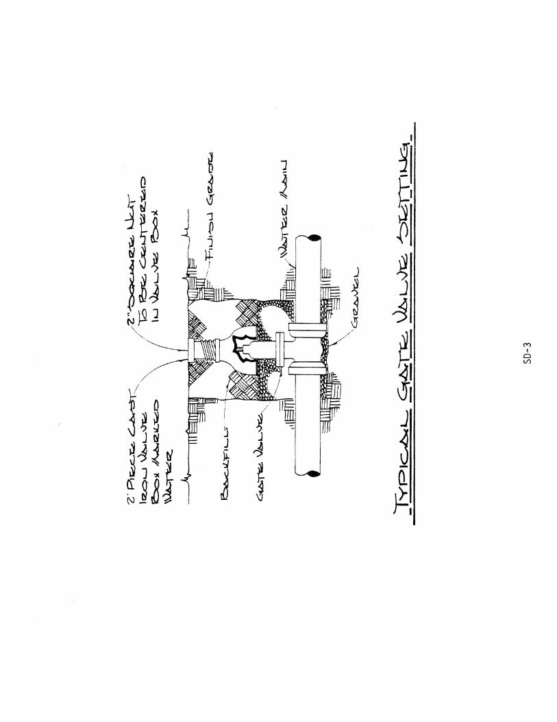

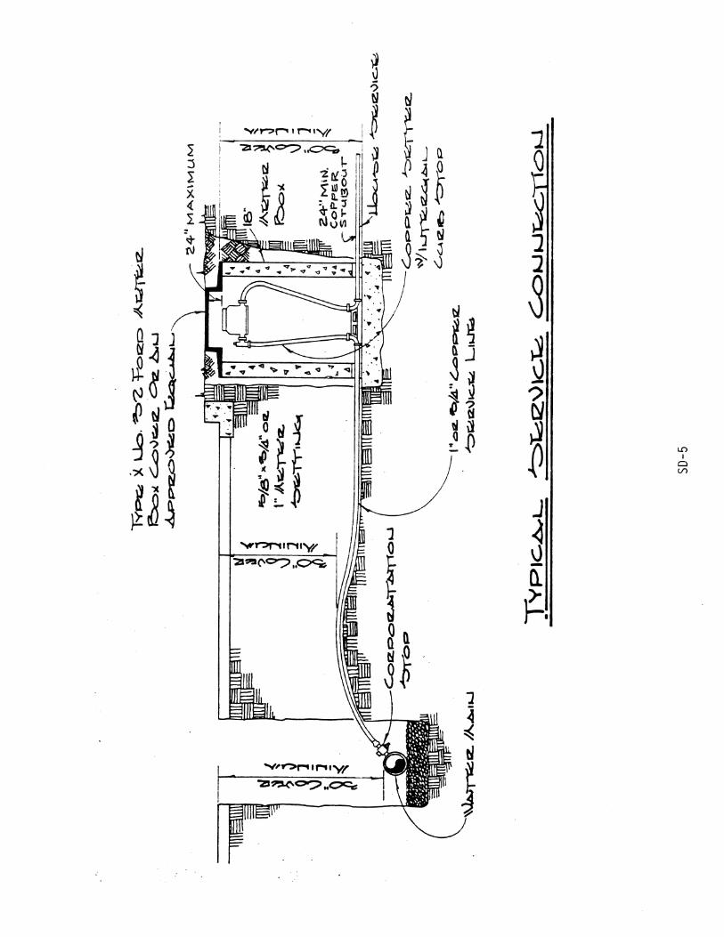

paul
Sticky Note
Accepted set by paul

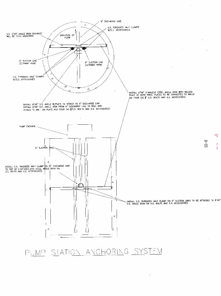
paul
Rectangle